US5263498A - Method of arthroscopically preparing an articular bone surface - Google Patents
Method of arthroscopically preparing an articular bone surfaceDownload PDFInfo
- Publication number
- US5263498A US5263498AUS08/016,176US1617693AUS5263498AUS 5263498 AUS5263498 AUS 5263498AUS 1617693 AUS1617693 AUS 1617693AUS 5263498 AUS5263498 AUS 5263498A
- Authority
- US
- United States
- Prior art keywords
- articular bone
- external
- bone
- cutting instrument
- femoral
- Prior art date
- Legal status (The legal status is an assumption and is not a legal conclusion. Google has not performed a legal analysis and makes no representation as to the accuracy of the status listed.)
- Expired - Lifetime
Links
- 210000000988bone and boneAnatomy0.000titleclaimsabstractdescription53
- 238000000034methodMethods0.000titleclaimsabstractdescription29
- 238000003801millingMethods0.000claimsabstractdescription39
- 210000001519tissueAnatomy0.000claimsdescription6
- 238000007493shaping processMethods0.000claimsdescription2
- 230000000295complement effectEffects0.000claims1
- 238000001356surgical procedureMethods0.000abstractdescription17
- 239000004568cementSubstances0.000abstractdescription15
- 238000013150knee replacementMethods0.000abstractdescription14
- 239000007943implantSubstances0.000abstractdescription3
- 238000002360preparation methodMethods0.000abstractdescription3
- 241001422033ThestylusSpecies0.000description26
- 210000003127kneeAnatomy0.000description17
- 230000033001locomotionEffects0.000description15
- 210000000689upper legAnatomy0.000description15
- 238000002271resectionMethods0.000description10
- 210000002303tibiaAnatomy0.000description8
- 210000002414legAnatomy0.000description6
- 210000004417patellaAnatomy0.000description6
- 210000000629knee jointAnatomy0.000description4
- 230000002093peripheral effectEffects0.000description4
- 208000014674injuryDiseases0.000description3
- 238000003780insertionMethods0.000description3
- 230000037431insertionEffects0.000description3
- 238000011084recoveryMethods0.000description3
- 230000008733traumaEffects0.000description3
- IJGRMHOSHXDMSA-UHFFFAOYSA-NAtomic nitrogenChemical compoundN#NIJGRMHOSHXDMSA-UHFFFAOYSA-N0.000description2
- 230000009471actionEffects0.000description2
- 210000003484anatomyAnatomy0.000description2
- 210000003423ankleAnatomy0.000description2
- 238000004891communicationMethods0.000description2
- 238000005553drillingMethods0.000description2
- 239000012530fluidSubstances0.000description2
- 210000002683footAnatomy0.000description2
- 230000005499meniscusEffects0.000description2
- 238000010408sweepingMethods0.000description2
- 206010041899Stab woundDiseases0.000description1
- 206010052428WoundDiseases0.000description1
- 210000000845cartilageAnatomy0.000description1
- 230000006835compressionEffects0.000description1
- 238000007906compressionMethods0.000description1
- 230000008878couplingEffects0.000description1
- 238000010168coupling processMethods0.000description1
- 238000005859coupling reactionMethods0.000description1
- 230000000994depressogenic effectEffects0.000description1
- 238000002224dissectionMethods0.000description1
- 210000005069earsAnatomy0.000description1
- 238000002513implantationMethods0.000description1
- 230000006872improvementEffects0.000description1
- 238000009434installationMethods0.000description1
- 238000012986modificationMethods0.000description1
- 230000004048modificationEffects0.000description1
- 229910052757nitrogenInorganic materials0.000description1
- 230000000399orthopedic effectEffects0.000description1
- 210000000426patellar ligamentAnatomy0.000description1
- 230000010076replicationEffects0.000description1
- 210000002435tendonAnatomy0.000description1
- 210000003906tibiofibular jointAnatomy0.000description1
Images


Classifications
- A—HUMAN NECESSITIES
- A61—MEDICAL OR VETERINARY SCIENCE; HYGIENE
- A61B—DIAGNOSIS; SURGERY; IDENTIFICATION
- A61B17/00—Surgical instruments, devices or methods
- A61B17/16—Instruments for performing osteoclasis; Drills or chisels for bones; Trepans
- A61B17/1662—Instruments for performing osteoclasis; Drills or chisels for bones; Trepans for particular parts of the body
- A61B17/1675—Instruments for performing osteoclasis; Drills or chisels for bones; Trepans for particular parts of the body for the knee
- A—HUMAN NECESSITIES
- A61—MEDICAL OR VETERINARY SCIENCE; HYGIENE
- A61B—DIAGNOSIS; SURGERY; IDENTIFICATION
- A61B17/00—Surgical instruments, devices or methods
- A61B17/16—Instruments for performing osteoclasis; Drills or chisels for bones; Trepans
- A61B17/1613—Component parts
- A61B17/1622—Drill handpieces
- A61B17/1624—Drive mechanisms therefor
- A—HUMAN NECESSITIES
- A61—MEDICAL OR VETERINARY SCIENCE; HYGIENE
- A61B—DIAGNOSIS; SURGERY; IDENTIFICATION
- A61B17/00—Surgical instruments, devices or methods
- A61B17/16—Instruments for performing osteoclasis; Drills or chisels for bones; Trepans
- A61B17/17—Guides or aligning means for drills, mills, pins or wires
- A61B17/1739—Guides or aligning means for drills, mills, pins or wires specially adapted for particular parts of the body
- A61B17/1764—Guides or aligning means for drills, mills, pins or wires specially adapted for particular parts of the body for the knee
- A—HUMAN NECESSITIES
- A61—MEDICAL OR VETERINARY SCIENCE; HYGIENE
- A61F—FILTERS IMPLANTABLE INTO BLOOD VESSELS; PROSTHESES; DEVICES PROVIDING PATENCY TO, OR PREVENTING COLLAPSING OF, TUBULAR STRUCTURES OF THE BODY, e.g. STENTS; ORTHOPAEDIC, NURSING OR CONTRACEPTIVE DEVICES; FOMENTATION; TREATMENT OR PROTECTION OF EYES OR EARS; BANDAGES, DRESSINGS OR ABSORBENT PADS; FIRST-AID KITS
- A61F2/00—Filters implantable into blood vessels; Prostheses, i.e. artificial substitutes or replacements for parts of the body; Appliances for connecting them with the body; Devices providing patency to, or preventing collapsing of, tubular structures of the body, e.g. stents
- A61F2/02—Prostheses implantable into the body
- A61F2/30—Joints
- A61F2/38—Joints for elbows or knees
- A—HUMAN NECESSITIES
- A61—MEDICAL OR VETERINARY SCIENCE; HYGIENE
- A61B—DIAGNOSIS; SURGERY; IDENTIFICATION
- A61B17/00—Surgical instruments, devices or methods
- A61B17/14—Surgical saws
- A61B17/15—Guides therefor
- A—HUMAN NECESSITIES
- A61—MEDICAL OR VETERINARY SCIENCE; HYGIENE
- A61B—DIAGNOSIS; SURGERY; IDENTIFICATION
- A61B17/00—Surgical instruments, devices or methods
- A61B17/16—Instruments for performing osteoclasis; Drills or chisels for bones; Trepans
- A61B17/1613—Component parts
- A61B17/1615—Drill bits, i.e. rotating tools extending from a handpiece to contact the worked material
- A—HUMAN NECESSITIES
- A61—MEDICAL OR VETERINARY SCIENCE; HYGIENE
- A61B—DIAGNOSIS; SURGERY; IDENTIFICATION
- A61B17/00—Surgical instruments, devices or methods
- A61B17/32—Surgical cutting instruments
- A61B17/320016—Endoscopic cutting instruments, e.g. arthroscopes, resectoscopes
- A—HUMAN NECESSITIES
- A61—MEDICAL OR VETERINARY SCIENCE; HYGIENE
- A61B—DIAGNOSIS; SURGERY; IDENTIFICATION
- A61B17/00—Surgical instruments, devices or methods
- A61B17/56—Surgical instruments or methods for treatment of bones or joints; Devices specially adapted therefor
- A61B17/58—Surgical instruments or methods for treatment of bones or joints; Devices specially adapted therefor for osteosynthesis, e.g. bone plates, screws or setting implements
- A61B17/68—Internal fixation devices, including fasteners and spinal fixators, even if a part thereof projects from the skin
- A61B17/70—Spinal positioners or stabilisers, e.g. stabilisers comprising fluid filler in an implant
- A61B17/7097—Stabilisers comprising fluid filler in an implant, e.g. balloon; devices for inserting or filling such implants
- A61B17/7098—Stabilisers comprising fluid filler in an implant, e.g. balloon; devices for inserting or filling such implants wherein the implant is permeable or has openings, e.g. fenestrated screw
- A—HUMAN NECESSITIES
- A61—MEDICAL OR VETERINARY SCIENCE; HYGIENE
- A61B—DIAGNOSIS; SURGERY; IDENTIFICATION
- A61B17/00—Surgical instruments, devices or methods
- A61B17/56—Surgical instruments or methods for treatment of bones or joints; Devices specially adapted therefor
- A61B17/58—Surgical instruments or methods for treatment of bones or joints; Devices specially adapted therefor for osteosynthesis, e.g. bone plates, screws or setting implements
- A61B17/88—Osteosynthesis instruments; Methods or means for implanting or extracting internal or external fixation devices
- A61B17/8802—Equipment for handling bone cement or other fluid fillers
- A61B17/8805—Equipment for handling bone cement or other fluid fillers for introducing fluid filler into bone or extracting it
- A61B17/8822—Equipment for handling bone cement or other fluid fillers for introducing fluid filler into bone or extracting it characterised by means facilitating expulsion of fluid from the introducer, e.g. a screw pump plunger, hydraulic force transmissions, application of vibrations or a vacuum
- A—HUMAN NECESSITIES
- A61—MEDICAL OR VETERINARY SCIENCE; HYGIENE
- A61B—DIAGNOSIS; SURGERY; IDENTIFICATION
- A61B17/00—Surgical instruments, devices or methods
- A61B2017/00535—Surgical instruments, devices or methods pneumatically or hydraulically operated
- A61B2017/00544—Surgical instruments, devices or methods pneumatically or hydraulically operated pneumatically
- A—HUMAN NECESSITIES
- A61—MEDICAL OR VETERINARY SCIENCE; HYGIENE
- A61B—DIAGNOSIS; SURGERY; IDENTIFICATION
- A61B17/00—Surgical instruments, devices or methods
- A61B17/16—Instruments for performing osteoclasis; Drills or chisels for bones; Trepans
- A61B2017/1602—Mills
- A—HUMAN NECESSITIES
- A61—MEDICAL OR VETERINARY SCIENCE; HYGIENE
- A61M—DEVICES FOR INTRODUCING MEDIA INTO, OR ONTO, THE BODY; DEVICES FOR TRANSDUCING BODY MEDIA OR FOR TAKING MEDIA FROM THE BODY; DEVICES FOR PRODUCING OR ENDING SLEEP OR STUPOR
- A61M1/00—Suction or pumping devices for medical purposes; Devices for carrying-off, for treatment of, or for carrying-over, body-liquids; Drainage systems
- A61M1/84—Drainage tubes; Aspiration tips
- A—HUMAN NECESSITIES
- A61—MEDICAL OR VETERINARY SCIENCE; HYGIENE
- A61M—DEVICES FOR INTRODUCING MEDIA INTO, OR ONTO, THE BODY; DEVICES FOR TRANSDUCING BODY MEDIA OR FOR TAKING MEDIA FROM THE BODY; DEVICES FOR PRODUCING OR ENDING SLEEP OR STUPOR
- A61M2205/00—General characteristics of the apparatus
- A61M2205/10—General characteristics of the apparatus with powered movement mechanisms
- A61M2205/103—General characteristics of the apparatus with powered movement mechanisms rotating
- Y—GENERAL TAGGING OF NEW TECHNOLOGICAL DEVELOPMENTS; GENERAL TAGGING OF CROSS-SECTIONAL TECHNOLOGIES SPANNING OVER SEVERAL SECTIONS OF THE IPC; TECHNICAL SUBJECTS COVERED BY FORMER USPC CROSS-REFERENCE ART COLLECTIONS [XRACs] AND DIGESTS
- Y10—TECHNICAL SUBJECTS COVERED BY FORMER USPC
- Y10S—TECHNICAL SUBJECTS COVERED BY FORMER USPC CROSS-REFERENCE ART COLLECTIONS [XRACs] AND DIGESTS
- Y10S623/00—Prosthesis, i.e. artificial body members, parts thereof, or aids and accessories therefor
- Y10S623/915—Method or apparatus for preparing biological material
- Y10S623/919—Bone
- Y—GENERAL TAGGING OF NEW TECHNOLOGICAL DEVELOPMENTS; GENERAL TAGGING OF CROSS-SECTIONAL TECHNOLOGIES SPANNING OVER SEVERAL SECTIONS OF THE IPC; TECHNICAL SUBJECTS COVERED BY FORMER USPC CROSS-REFERENCE ART COLLECTIONS [XRACs] AND DIGESTS
- Y10—TECHNICAL SUBJECTS COVERED BY FORMER USPC
- Y10T—TECHNICAL SUBJECTS COVERED BY FORMER US CLASSIFICATION
- Y10T407/00—Cutters, for shaping
- Y10T407/19—Rotary cutting tool
- Y10T407/1946—Face or end mill
- Y10T407/1948—Face or end mill with cutting edge entirely across end of tool [e.g., router bit, end mill, etc.]
Definitions
- the present inventionpertains to resection of bones for receiving prosthetic components of particular use in knee replacement procedures and, more specifically, to methods and apparatus for arthroscopic knee replacement.
- Prosthetic replacement of the kneeis a procedure of substantial importance to recreate the knee joint with a pain-free functional arc of motion and antero-posterior and varus-valgus stability.
- the kneeis, basically, formed of medial and lateral tibial plateaus, medial and lateral femoral condyles and menisci between the tibial plateaus and the femoral condyles along with the patella which covers the anterior surface of the knee, and prosthetic replacement of the knee as described herein relates to the tibial plateaus, the femoral condyles and the menisci.
- prosthesesare presently available, as described in detail in Replacement of the Knee, Laskin, Denham and Apley, Springer-Verlag Berlin Heidelberg, 1984, and are commonly grouped as partial or unicompartmental replacements of the medial or lateral portion of the tibio-femoral joint, surface replacements to prevent contact between worn surfaces and jack the joint surfaces apart, linked joints and fixed hinge joints.
- the type of prothesis employedmust be matched to the needs of the patient. By selecting the proper prothesis, antero-posterior and varus-valgus stability can be achieved by prosthetic replacement coupled with bone surfacing or resection.
- Open surgery required for prior art prosthetic replacementstypically necessitates a long incision, on the order of ten inches, along the anterior midline of the knee from above the patella to below the tibial tubercle followed by a deep dissection around the medial border of the patella and along the patellar ligament to the tibial tubercle with detachment of the medial third of the quadriceps attachment from the upper border of the patella.
- the tendinous marginis then pulled downwards and medially while the patella is pulled downwards and laterally.
- the quadriceps tendonis then split, and the patella is displaced laterally and everted. While the above is a simplified explanation of open knee surgery, it serves to explain the substantial trauma and recovery time associated therewith.
- Another object of the present inventionis to accurately resect tibial plateau and femoral condyle planar surfaces relative to each other such that the tibial plateau and femoral condyle surfaces are constrained to be disposed in planes perpendicular to a substantially vertical reference plane.
- a further object of the present inventionis to cement a prosthesis to a tissue surface after the prosthesis is accurately placed on the tissue surface.
- An additional object of the present inventionis to perform a least invasive prosthetic knee replacement with the use of arthroscopy and requiring only arthroscopic size portals.
- the present inventionhas another object in the performing of all procedures for a prosthetic knee replacement, including surface preparation, fitting and implanting, arthroscopically through small portals enlarged only for insertion of the final components.
- Yet an additional object of the present inventionis to arthroscopically resect tibial plateau an femoral condyle surfaces using existing surface anatomy as a reference point.
- a further object of the present inventionis to improve the mechanical bond created by cement between a prosthesis and a bone surface by applying suction to the bone to draw the cement into the bone.
- Some of the advantages of the present invention over prior art prosthetic knee replacementsare that by using arthroscopic surgical techniques and small portals in place of the long incisions required for open knee procedures, trauma and recovery time are substantially reduced, alignment of the tibial and femoral prosthesis components is assured by fixing the femoral cutting jig with reference to the tibial cutting jig and, therefore, resecting the femoral condyle with reference to the resected tibial plateau, the knee is restored to a normal, healthy condition by resecting the tibial plateau and the tibial condyle using the existing surface anatomy as a reference point, and prostheses are cemented after accurate positioning of the prostheses on the bone.
- the present inventioncontemplates the use of a milling cutter to prepare a bone surface to receive a prosthesis such that bone surfaces can be resected through small portals allowing prosthesis implantation using arthroscopic surgical techniques and, more particularly, allowing arthroscopic, unicompartmental, prosthetic total knee replacement.
- Tibial and femoral prosthesis componentsare bonded to the bone surfaces by injecting cement after the components are accurately positioned on the bone, the cement being injected through the components to be received in chambers defined by recesses in the fixation surfaces of the components and the cement bond being enhanced by applying suction to the bone to draw the cement into the bone.
- FIG. 1is a perspective view of a tibial jig mounted to the tibia in accordance with the present invention.
- FIG. 2is an exploded view of the tibial jig, a support assembly and a milling cutter module in accordance with the present invention.
- FIG. 3is a side view of the apparatus of FIG. 2 in position for resecting the tibial plateau.
- FIG. 3ais a view taken along lines 3a-3a of FIG. 3 showing a depth of gauge scale.
- FIG. 4is a front view of the tibial plateau during the resecting thereof.
- FIG. 5is a top view of the tibial plateau after longitudinal cuts are made therein.
- FIG. 6is a side view of the tibial plateau after resecting to produce a planar tibial plateau surface.
- FIG. 7is a plan view of the milling cutter module mounted on a support platform.
- FIG. 7ais a section taken along lines 7A--7A of FIG. 7 showing a stop for limiting pivotal movement of the milling cutter.
- FIG. 8is a side view, partly in section, of the milling cutter module on a slide member of the platform.
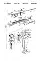
- FIG. 9is a broken plan view of the milling cutter according to the present invention.
- FIG. 10is a section taken along lines 10--10 of FIG. 9
- FIG. 10ais a distal end view of the milling cutter of FIG. 9.
- FIG. 11is a side view of the cutter platform with an alignment bridge mounted thereon for drilling holes in the femur.
- FIG. 12is a perspective view of the alignment bridge.
- FIG. 13is a top view taken along line 13--13 of FIG. 11.
- FIG. 14is a top view showing rods passing through the holes drilled in the femur for attachment of a femoral jig.
- FIG. 15is a broken side view partly in section of a rod for passing through the femur.
- FIG. 16is an exploded broken view, partly in section, of sleeves received on the rods.
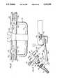
- FIG. 17is an exploded perspective view of a femoral support base.
- FIG. 18is a top plan view of the femoral support base.
- FIG. 19is a broken side view of the femoral jig with the cutter platform and the cutter module mounted thereon.
- FIGS. 20, 21 and 22are perspective views showing resecting of a femoral condyle to produce planar posterior, distal and chamfer surfaces, respectively.
- FIG. 23is a broken section of a holding detent for the tibial jig.
- FIG. 24is an exploded view illustrating the prepared tibial plateau and femoral condyle surfaces and positioning of the tibial and femoral prothesis components thereon.
- FIG. 25is a side view of a stylus for use in resecting the tibial plateau and the femoral condyle.
- FIG. 26is a perspective view of a module for the stylus mounted on the platform slide member.
- FIGS. 27, 28 and 29are perspective views showing use of the stylus for positioning the cutter platform for resecting the tibial plateau and the femoral condyle.
- FIG. 30is a broken perspective view showing use of a gauge for selecting the size of a femoral prosthesis component.
- prosthetic knee replacement in accordance with the present inventionrequires only small portals to perform all bone and tissue preparation procedures as well as implanting the prosthetic tibial and femoral components and cementing the components in place. Accordingly, prosthetic knee replacement in accordance with the present invention can be performed with the use of arthroscopic surgical procedures.
- portalis meant a puncture or stab wound of the type made by a plunge cut with a scalpel or trocar and of the type commonly used in conventional arthoscopic procedures, the size of the portal being just large enough to allow insertion of instruments.
- a tibial jig 40 in accordance with the present inventionis illustrated in FIG. 1 and includes a lower V-block 42 adapted to rest just above the malleoli at the ankle and an upper V-block 44 adapted to be secured to the tibia just below the tibial tubercle.
- Lower V-block 42is connected to a rod 46 telescopingly received within a tube 48 connected to upper V-block 44 which is formed of a pair of angled members having a plurality of holes 50 therein to receive screws 52 extending therethrough and into the tibia to securely mount the tibial jig thereon.
- FIG. 1A tibial jig 40 in accordance with the present invention is illustrated in FIG. 1 and includes a lower V-block 42 adapted to rest just above the malleoli at the ankle and an upper V-block 44 adapted to be secured to the tibia just below the tibial tubercle.
- Lower V-block 42is connected to a rod 46 telescoping
- tube 48has spaced arms 54 and 56 terminating at the angled members of upper V-block 44, and an angular adjustment member 58 has a tongue 60 disposed between members 54 and 56 with a hole 62 therein for receiving an adjustment screw 64 extending through corresponding holes in members 54 and 56.
- the angular adjustment member 58can be pivoted about screw 64 to a desired position and the screw tightened to hold the angular adjustment member in place.
- a longitudinal adjustment block 66has a dovetail slot 68 therein to receive a dovetail 70 on member 58, and a longitudinal adjustment screw 72 is held in a non-rotating manner in block 66 and carries a head 74 having a dovetail slot 76 therein.
- Block 66has spaced arms between which is mounted a thumbwheel 76 threadedly engaging adjustment screw 72 such that rotation of thumbwheel 76 causes longitudinal axial movement of the screw and the head.
- a block 80has a dovetail 82 received in slot 76 and mounts a cutter platform generally indicated at 84.
- a longitudinal or depth of cut gauge 86is mounted on an extension 88 of block 66 and carries indicia 90 allowing registration with an index mark on screw 72 to indicate the depth of a cut being made, as will be explained in more detail hereinafter.
- the gaugehas a zero center mark with indicia extending in either direction therefrom in millimeter graduations.
- the platform 84includes a semi-circular plate 92 having a curved peripheral edge 94 and a dovetail 96 slidably received in a dovetail slot 98 in block 80 to permit movement of the platform in a lateral direction perpendicular to the longitudinal movement of screw 72.
- a linear slide member 100has a distal end 102 pivotally mounted centrally on plate 92 and carries a toothed rack 104 longitudinally thereon.
- the slide member 100extends substantially beyond the peripheral edge 94 of plate 92 and carries on its back side a clamp assembly including a lever 106 pivotally mounted on ears 108 secured to the slide member, the lever 106 having a clamping end 110 and an operating end 112 as best shown in FIG. 8.
- a trigger like member 114is pivotally mounted on a lug 116 extending from the slide member and has a flat portion engaging the operating end 112 of lever 106 which is biased against the trigger by means of a compression spring 118. Accordingly, when trigger 114 is moved toward the slide member (rotated clock-wise looking at FIG. 8) the operating end 112 of lever 106 is moved toward the slide member causing the clamping end 110 to move away from the peripheral edge 94 of plate 92 thereby allowing pivotal movement of the slide member relative to the plate. When the trigger 114 is released, the spring 118 returns the clamping end 110 to engagement with the plate to hold the slide member in the selected pivotal position.
- the slide memberhas an elongated dovetail 121 received in a slot 122 in a housing 124 of a cutter module generally indicated at 126.
- a pinion 128 having teeth for engaging rack 104is mounted on an axle journaled through housing 124 to terminate at handwheels 132 on either side of the housing.
- a pneumatic motor 134has a proximal end receiving drive and exhaust conduits 136 and a distal end engaging the shaft of a milling cutter 138 as best shown in FIG. 8.
- the motoris driven by pressurized fluid, such as nitrogen or air; and, when the drive fluid is provided at 100 psi, the motor speed and torque are 4000 rpm and 50 oz-inch, respectively.
- a chamber 140is formed around the drive coupling and has a port 142 for connection to a source of suction, the proximal end of the milling cutter 138 having a hole 144 therein for communicating with the chamber and the milling cutter 138 being rotatably supported at the distal end of the chamber by suitable bearing and journal structure.
- Stops 146 and 148are movably secured to the peripheral edge 94 of plate 92 on opposite sides of slide member 100; and, as shown in FIG. 7a, are formed of set screws 150 for engaging the plate 92.
- the milling cutter 138includes a shaft having a proximal end 152 for engaging a locking collet assembly in chamber 140 to be driven by the pneumatic motor, the shaft being hollow to establish communication between hole 144 in the proximal end thereof and holes 154 disposed in the distal portion thereof.
- the distal portion of the milling cutterincludes a body 156 having a plurality of helical cutting edges 158 extending therealong, and at least one hole 154 is disposed between each pair of body cutting edges 158. As shown in FIG. 10, four equally spaced cutting edges are disposed on the fluted body 156, and holes 154 communicate with a passage 160 formed by the hollow shaft of the milling cutter.
- Cutting edges 162are disposed at the distal end of the milling cutter in a plane extending transverse to the longitudinal axis of the milling cutter, and each of the body cutting edges 158 extends from one of the distal end cutting edges 162.
- the milling cutterpreferably has a diameter of 7 mm and the body cutting edges preferably have substantially radial leading edges.
- tibial jig 40is secured to the tibia by screws 52 extending through V-block 44 and into the tibia with the upper and lower V-blocks disposed just below the tibial tubercle and just above the malleoli at the ankle, respectively, with a set screw 163 provided to maintain the position of telescoping members 46 and 48.
- a portal 164is formed in the knee for insertion of an arthroscope 166 for viewing of the knee and the surgical procedure, while a portal 168 is formed in the tissue adjacent the tibial plateau, FIG. 1 illustrating the portal 168 for use in resecting the medial tibial plateau of the left leg.
- the stylus module 170includes a housing having a dovetail slot for receiving the dovetail 120 of the slide member and mounts a stylus 172 having four equally spaced positions controlled by detents, not shown, within the housing.
- the stylushas a curved radially extending tip 174 that can be positioned via the detents to extend up, down or to either side.
- the radial extension of the stylus 174is preferably equal to the radius of the milling cutter, e.g., 3.5 mm, and the housing of the stylus module positions the stylus at the same position at which the milling cutter is positioned when the cutter module is received on the slide member.
- angular adjustment block 58is pivoted about screw 64 to align the platform with the natural tilt of the tibial plateau as sensed by the stylus, the natural tilt being normally between 3° and 10° posteriorly.
- the stylusis rotated 90° such that the tip 174 is turned to the right, and the tip of the stylus is moved by sliding the plate 92 in block 80 until the tip of the stylus contacts the tibial eminence 176 as illustrated in FIG. 27.
- a screwnot shown, is tightened to secure the lateral position of the platform.
- the slide member 100is centrally positioned on the plate 92 during this procedure, and the stop 148 is moved to abut the slide member 100 to prevent pivotal movement of the slide member and the milling cutter mill clockwise looking at FIG. 7.
- the tip 174 of the stylusturned down, the lowest point of contact of the tip on the tibial plateau is located; and, with the stylus at this contact point, thumbwheel 78 is locked in place to control the position of the resection to be performed, it being noted that, due to the dimensional relationship between the cutter module and the stylus module, the milling cutter will be aligned with the lowest point on the tibial plateau. As shown in dashed lines in FIG.
- the anterior portion of the meniscus or cartilagehas been removed by normal arthroscopic techniques leaving a posterior segment indicated at 178 such that during the resection procedure, the posterior portion of the meniscus provides a cushion to provide the surgeon with an indication of the location of the posterior edge of the tibial plateau.
- the stylus moduleis removed and the cutter module is placed thereon as illustrated in FIG. 3; and, since angular, lateral and longitudinal adjustments have already been made and set in place, only linear and pivotal movements of the milling cutter can be made and such movements can be made only in a single plane.
- initial forward movement of the milling cutterproduces a longitudinal plunge cut along the tibial eminence 176 to produce a trough across the tibial plateau as indicated at 180, it being noted that the milling cutter cuts on its distal end as well as along the fluted body thereof.
- the trigger 114is released allowing pivotal movement of the slide member slightly; and, after the trigger is released to clamp the slide member in position, a second longitudinal cut is made by linear movement of the milling cutter as indicated at 182. This procedure is repeated until the surface of the tibial plateau is covered with troughs having ridges 184 therebetween.
- the trigger 114is now depressed to release the slide member; and, with the milling cutter disposed over the tibial plateau, the milling cutter is pivoted back and forth to sweep the milling cutter over the tibial plateau removing the ridges, the sweeping movement being substantially transverse to the longitudinal movements of the milling cutter to form the troughs.
- suctionis applied to port 142 such that bone chips are evacuated via holes 154 and passage 160 through the hollow milling cutter. The suction also serves to cool the surgical site and prevent cavitation.
- the alignment bridge 186includes a dovetail slide 188 received in the slot 98 in block 80, and an arm 190 extends at an angle of 45° between slide 188 and a drill guide 192 having parallel bores 194 and 196 therethrough. Accordingly, the bores 194 and 196 will be disposed in a plane transverse to the plane of the resected tibial plateau.
- inserts 198 and 200are passed through bores 194 and 196, respectively, to provide elongated guides for drilling parallel bores through the femur.
- the boresare drilled through the femur using conventional orthopedic techniques; and, after the bores are drilled through the femur, threaded rods 204 are passed through each bore as illustrated in FIG. 14.
- one of the threaded rods 204is preferably hollow having a passage 206 therethrough providing communication between its end and holes 208 centrally located therein.
- Threaded sleeves 210are disposed on the outer ends of each rod in threaded engagement with the rods while loosely sliding sleeves 212 are disposed between sleeves 210 and the femur, the sleeves being illustrated in FIG. 16 and shown in position relative to the femur in FIG. 14.
- a support for resecting the femoral condyleis established relative to the resected tibial plateau since the rods are disposed in a plane perpendicular to the planar tibial plateau.
- a femoral support base 214is rigidly attached to the rods to prevent any deflection or twisting of the rods.
- the femoral support base 214includes a U-shaped member 216 having upper ends secured saddles 218 each of which has a cylindrical protrusion 220 extending upwardly therefrom and side walls 219 spaced from the cylindrical protrusion to allow the sleeves 210 to fit therebetween.
- Conical washers 222are secured over the sleeves by means of screws 224 received in threaded holes 226 in the saddles 218 such that the washers abut the sleeves to firmly hold the rods in parallel position.
- a femoral cutting jig 228is mounted to the femoral support base 214 via threaded posts 230 extending through the cylindrical protrusions 220 to receive threaded nuts 232 tightening the femoral cutting jig in rigid position relative to the femoral support base.
- the femoral cutting jigincludes a U-shaped member 234 having opposite legs pivotally mounted on flanges 236 each of which is rigidly secured to the femoral support base via threaded post 230. As best shown in FIGS.
- each of the flanges 236has holes 238, 240 and 242 therein positioned relative to the pivotal axis indicated at 244 to position a support 246 rigidly connected with the U-shaped member 234 in a plane parallel to the plane passing through the rods through the femur as illustrated in FIG. 21, a plane perpendicular to the plane passing through the rods as illustrated in FIG. 20, and a plane positioned at an angle of 45° to the plane passing through the rods as illustrated in FIG. 22.
- the position of the U-shaped member and therefore the support 246is controlled by means of spring loaded detents mounted on flanges 248 secured to the opposite ends of the U-shaped member. As shown in FIG.
- detents 250are biased inwardly to extend through holes 238, 240 or 242 with which they are aligned, and can be withdrawn by twisting end 252 to cause the end to cam outwardly as shown in phantom compressing a spring 254 to move the detent out of the hole. Accordingly, the femoral cutting jig can be accurately positioned in either of the three positions shown in FIGS. 20, 21 and 22 by manipulating the detents and pivoting the U-shaped member relative to the femoral support base.
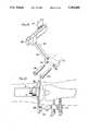
- the femoral cutting jig illustrated in FIG. 19differs slightly from that illustrated in FIGS.
- FIG. 19illustrates the milling cutter positioned at an angle of 45° to the plane of the rods 204 through the femur and further illustrates, in phantom, the milling cutter positioned in planes perpendicular and parallel to the plane of the rods 204.
- the milling cutteris constrained to move only in planes parallel to a reference plane extending perpendicular to the plane of the resected tibial plateau.
- the stylus module 170is mounted on the slide member 100 with the stylus 172 turned upward as illustrated at 256 in FIG. 29 and the slide member positioned in a plane parallel to the resected tibial plateau plane, and the stylus is moved to contact the lowermost point on the posterior surface of the femoral condyle.
- the depth gauge 86is moved to align the "zero" point with the index line on the screw 72. With the depth gauge so aligned, the stylus module is removed, and the thumbwheel 78 is rotated to move the cutting platform 7 millimeters toward the femoral condyle as indicated by the gauge 86.
- the cutting moduleis positioned on the slide member and the posterior portion of the femoral condyle is resected in the same manner as described above with respect to the tibial plateau, that is, by forming a plurality of longitudinal troughs in the bone and removing the ridges therebetween by sweeping the milling cutter.
- FIG. 20it can be seen that resecting of the posterior surface of the femoral condyle is accomplished by passing the milling cutter and the stylus through the same portal 168 utilized to resect the tibial plateau.
- the distal surface of the femoral condyleis resected by moving the femoral cutting jig to position the platform in a plane perpendicular to the plane of the rods passing through the femur and the plane of the resected posterior surface of the femoral condyle.
- the stylus module and the depth gaugeare used in the same manner as described with respect to the resecting of the posterior surface; however, as illustrated in FIG. 21, a second portal 258 disposed between an inch and an inch and a half above portal 168 is utilized for the distal surface cutting procedure. As shown in FIG.
- the stylusis turned toward the condyle as indicated at 260; and, when the resecting procedure is completed, the resected planar distal surface will be perpendicular to the resected planar posterior surface. Resection of the distal surface is accomplished in the same manner as described above with respect to the tibial plateau and the posterior surface.
- the femoral cutting jigis pivoted to the position illustrated in FIG. 22 such that the platform is disposed in a plane at an angle of 45° to the distal and posterior resected surfaces.
- the stylusis mounted on the platform and passed through portal 258 to contact the uncut portion of the femoral condyle between the resected posterior and distal surfaces as shown at 262, and the depth gauge and cutter module are utilized in the same manner as described above to cut a chamfer surface between the distal and posterior surfaces, the chamfer surface being disposed in a plane at an angle of 45° to the planes of the distal and posterior surfaces.
- a plurality of semi-circular gauges 264each having an anterior foot 266 and a posterior foot 268, are provided; and, to determine the length of the chamfer cut, individual gauges are attached to a rod 270 inserted through portal 258 and aligned with the chamfer cut to determine the size of the femoral prothesis for use with the contoured femoral condyle.
- FIG. 24illustrates the medial compartment of the knee after resection and it will be appreciated that the planes of each of the posterior, distal and chamfer cuts on the femoral condyle are parallel to a reference plane perpendicular to the plane of the tibial plateau, the reference plane being substantially vertical thereby producing a normal healthy knee joint.
- the resected planar tibial plateauis indicated at 272
- the posterior planar femoral condyle cutis indicated at 274
- the distal planar femoral condyle cutis indicated at 276
- the chamfer planar femoral condyle cutis indicated at 278.
- the area between portals 168 and 258is incised to increase the size of the portal to about one and one-half inches as indicated at 280.
- the tibial jigis removed once the rods are inserted in the femur to establish the femoral support base; and, once the resections are completed, the femoral support base and the femoral cutting jig are removed.
- a drill guide 282 mounted on a rod 284is inserted into the joint through portal 280, the drill guide having a distal portion for abutting distal planar surface 276 and a chamfer portion 286 for abutting chamfer surface 278, the angle between portions 286 and 288 being 45° to equal the angle between distal surface 276 and chamfer surface 278.
- spaced holes 290are drilled in the distal surface. Since the same amount of bone has been removed from each cut during contouring of the femoral condyle, a femoral prothesis component 292 can be implanted on the femoral condyle reproducing the natural condyle.
- Tibial component 292has a polycentric bearing surface 294 with an inner fixation surface 296 for engaging the posterior, distal and chamfer surfaces, and spaced tapered posts 298 extend from a distal portion of the femoral component to be received in holes 290.
- a channel 300is formed in the femoral component to communicate with a recess 302 formed in the fixation surface 296 such that the femoral component can be installed in proper position on the prepared femoral condyle with the posts 298 received in the holes 290; and, thereafter, cement can be introduced between the femoral component and the bone via channel 300, the cement filling the recess 302 and producing a mechanical bond with the bone.
- the mechanical bond of the cement with the boneis enhanced by applying suction to rod 204, the suction being communicated via passage 206 and holes 208 and through the porous bone to draw the cement into the bone.
- a trial tray similar in shape to tibial component 304 illustrated in FIG. 24is placed on tibial plateau 272 via portal 280 to obtain the correct size, and various bearing inserts similar to bearing insert 306 illustrated in FIG. 24 are positioned in cavities in the tray to provide the desired tibial component thickness allowing alignment of the femur and tibia with the femoral component bearing on the bearing insert.
- a permanent tibial prothesis implant 304is passed through portal 280 and secured to tibial plateau 272.
- the tibial component 304has a cavity 308 in the upper surface thereof for receiving bearing insert 306 in locking engagement, and, similar to femoral component 292, a recess 310 is formed in a bottom fixation surface 312 and a channel 314 communicates therewith for supplying cement to the tibial component after the tibial component is placed on the tibial plateau.
- a bone screwpasses through an angled hole 316 in an anterior portion of the tibial prothesis 304 to hold the prothesis o the tibial plateau.
- the method and apparatus of the present inventionpermits prosthetic knee replacement utilizing arthroscopic surgical procedures. Additionally, the method and apparatus provide advantages useful in open knee surgery also in that the cuts in accordance with the present invention are different for each individual since each cut is sensed from the surface and not from a previous cut thereby restoring a natural knee action in that making the cuts with reference to bone surfaces allows replication of the previous bone structure thereby not forcing alignment and allowing the compartment to be matched with the other compartments of the knee. Additionally, by establishing the femoral jig in the femur in relation to the tibial plateau, alignment of the femoral and tibial protheses is assured with bearing contact along a line laterally through the knee joint.
- the platform and cutting modulepermit the cutting action to be performed by the surgeon with only one hand allowing his second hand to move the arthroscope or to provide better viewing in open surgery.
- the resecting of bone using a pivoting movement of a cutteris particularly advantageous in that, by placing the pivot point just external of the body, small portals can be used in accordance with arthroscopic techniques.
Landscapes
- Health & Medical Sciences (AREA)
- Life Sciences & Earth Sciences (AREA)
- Surgery (AREA)
- Orthopedic Medicine & Surgery (AREA)
- Veterinary Medicine (AREA)
- General Health & Medical Sciences (AREA)
- Oral & Maxillofacial Surgery (AREA)
- Engineering & Computer Science (AREA)
- Biomedical Technology (AREA)
- Heart & Thoracic Surgery (AREA)
- Public Health (AREA)
- Animal Behavior & Ethology (AREA)
- Molecular Biology (AREA)
- Nuclear Medicine, Radiotherapy & Molecular Imaging (AREA)
- Medical Informatics (AREA)
- Dentistry (AREA)
- Physical Education & Sports Medicine (AREA)
- Cardiology (AREA)
- Transplantation (AREA)
- Vascular Medicine (AREA)
- Prostheses (AREA)
- Surgical Instruments (AREA)
- Materials For Medical Uses (AREA)
Abstract
Description
Claims (5)
Priority Applications (1)
| Application Number | Priority Date | Filing Date | Title |
|---|---|---|---|
| US08/016,176US5263498A (en) | 1990-01-08 | 1993-01-26 | Method of arthroscopically preparing an articular bone surface |
Applications Claiming Priority (3)
| Application Number | Priority Date | Filing Date | Title |
|---|---|---|---|
| US07/462,529US5171244A (en) | 1990-01-08 | 1990-01-08 | Methods and apparatus for arthroscopic prosthetic knee replacement |
| US77321491A | 1991-10-09 | 1991-10-09 | |
| US08/016,176US5263498A (en) | 1990-01-08 | 1993-01-26 | Method of arthroscopically preparing an articular bone surface |
Related Parent Applications (1)
| Application Number | Title | Priority Date | Filing Date |
|---|---|---|---|
| US77321491AContinuation-In-Part | 1990-01-08 | 1991-10-09 |
Publications (1)
| Publication Number | Publication Date |
|---|---|
| US5263498Atrue US5263498A (en) | 1993-11-23 |
Family
ID=23836773
Family Applications (5)
| Application Number | Title | Priority Date | Filing Date |
|---|---|---|---|
| US07/462,529Expired - LifetimeUS5171244A (en) | 1990-01-08 | 1990-01-08 | Methods and apparatus for arthroscopic prosthetic knee replacement |
| US07/785,429Expired - LifetimeUS5228459A (en) | 1990-01-08 | 1991-10-09 | Method of resecting bone |
| US07/773,213Expired - LifetimeUS5304181A (en) | 1990-01-08 | 1991-10-09 | Methods and apparatus for arthroscopic prosthetic knee replacement |
| US07/785,428Expired - LifetimeUS5395376A (en) | 1990-01-08 | 1991-10-09 | Method of implanting a prosthesis |
| US08/016,176Expired - LifetimeUS5263498A (en) | 1990-01-08 | 1993-01-26 | Method of arthroscopically preparing an articular bone surface |
Family Applications Before (4)
| Application Number | Title | Priority Date | Filing Date |
|---|---|---|---|
| US07/462,529Expired - LifetimeUS5171244A (en) | 1990-01-08 | 1990-01-08 | Methods and apparatus for arthroscopic prosthetic knee replacement |
| US07/785,429Expired - LifetimeUS5228459A (en) | 1990-01-08 | 1991-10-09 | Method of resecting bone |
| US07/773,213Expired - LifetimeUS5304181A (en) | 1990-01-08 | 1991-10-09 | Methods and apparatus for arthroscopic prosthetic knee replacement |
| US07/785,428Expired - LifetimeUS5395376A (en) | 1990-01-08 | 1991-10-09 | Method of implanting a prosthesis |
Country Status (8)
| Country | Link |
|---|---|
| US (5) | US5171244A (en) |
| EP (1) | EP0511244B1 (en) |
| JP (1) | JPH05503643A (en) |
| AT (1) | ATE172372T1 (en) |
| AU (1) | AU659080B2 (en) |
| CA (1) | CA2073349C (en) |
| DE (1) | DE69130391T2 (en) |
| WO (1) | WO1991010408A1 (en) |
Cited By (139)
| Publication number | Priority date | Publication date | Assignee | Title |
|---|---|---|---|---|
| US5431653A (en)* | 1993-07-06 | 1995-07-11 | Callaway; George H. | Knee joint flexion-gap distraction device |
| WO1995030388A1 (en)* | 1994-05-06 | 1995-11-16 | Advanced Bio Surfaces, Inc. | Joint resurfacing system |
| US5474559A (en)* | 1993-07-06 | 1995-12-12 | Zimmer, Inc. | Femoral milling instrumentation for use in total knee arthroplasty with optional cutting guide attachment |
| US5593411A (en)* | 1995-03-13 | 1997-01-14 | Zimmer, Inc. | Orthopaedic milling guide for milling intersecting planes |
| US5601563A (en)* | 1995-08-25 | 1997-02-11 | Zimmer, Inc. | Orthopaedic milling template with attachable cutting guide |
| US5609645A (en)* | 1994-10-28 | 1997-03-11 | Intermedics, Inc. | Knee revision prosthesis with shims |
| US5643272A (en)* | 1994-09-02 | 1997-07-01 | Hudson Surgical Design, Inc. | Method and apparatus for tibial resection |
| US5649929A (en)* | 1995-07-10 | 1997-07-22 | Callaway; George Hadley | Knee joint flexion-gap distraction device |
| US5653714A (en)* | 1996-02-22 | 1997-08-05 | Zimmer, Inc. | Dual slide cutting guide |
| US5658293A (en)* | 1995-10-10 | 1997-08-19 | Zimmer, Inc. | Guide platform associated with intramedullary rod |
| US5743915A (en)* | 1993-07-06 | 1998-04-28 | Zimmer, Inc. | Femoral milling instrumentation for use in total knee arthoroplasty with optional cutting guide attachment |
| US5755803A (en)* | 1994-09-02 | 1998-05-26 | Hudson Surgical Design | Prosthetic implant |
| US5810827A (en)* | 1994-09-02 | 1998-09-22 | Hudson Surgical Design, Inc. | Method and apparatus for bony material removal |
| US6059831A (en)* | 1999-03-31 | 2000-05-09 | Biomet, Inc. | Method of implanting a uni-condylar knee prosthesis |
| US6132468A (en)* | 1998-09-10 | 2000-10-17 | Mansmann; Kevin A. | Arthroscopic replacement of cartilage using flexible inflatable envelopes |
| US6427698B1 (en)* | 2001-01-17 | 2002-08-06 | Taek-Rim Yoon | Innominate osteotomy |
| US6482209B1 (en)* | 2001-06-14 | 2002-11-19 | Gerard A. Engh | Apparatus and method for sculpting the surface of a joint |
| US6488687B1 (en)* | 1997-09-18 | 2002-12-03 | Medidea, Llc | Joint replacement method and apparatus |
| US20030088314A1 (en)* | 2001-11-05 | 2003-05-08 | Tomoaki Koseki | Alveolar bone extension apparatus |
| US20030100906A1 (en)* | 2001-11-28 | 2003-05-29 | Rosa Richard A. | Methods of minimally invasive unicompartmental knee replacement |
| US20030236523A1 (en)* | 2001-06-14 | 2003-12-25 | Johnson Wesley D. | Apparatus and method for minimally invasive total joint replacement |
| US6695848B2 (en)* | 1994-09-02 | 2004-02-24 | Hudson Surgical Design, Inc. | Methods for femoral and tibial resection |
| US6699252B2 (en)* | 2001-04-17 | 2004-03-02 | Regeneration Technologies, Inc. | Methods and instruments for improved meniscus transplantation |
| US6716212B1 (en)* | 2002-01-25 | 2004-04-06 | Tyrone Sam Pickens | Universal modular external fixation system |
| US20040078042A1 (en)* | 1997-09-18 | 2004-04-22 | Masini Michael A. | Bone-conserving orthopedic instrumentation and appliances |
| US20050027299A1 (en)* | 2003-07-28 | 2005-02-03 | Robert Metzger | Method and apparatus for minimally invasive distal femoral resection |
| US20050049594A1 (en)* | 2001-04-20 | 2005-03-03 | Wack Michael A. | Dual locking plate and associated method |
| US6884247B1 (en) | 2003-10-09 | 2005-04-26 | Wright Medical Technology Inc. | Methods for treating osteolytic bone lesions |
| US20050137599A1 (en)* | 2003-12-19 | 2005-06-23 | Masini Michael A. | Instrumentation and methods for refining image-guided and navigation-based surgical procedures |
| US20050154398A1 (en)* | 2002-12-03 | 2005-07-14 | Anthony Miniaci | Retrograde delivery of resurfacing devices |
| US20050154331A1 (en)* | 2003-12-30 | 2005-07-14 | Christie Michael J. | Minimally invasive bone miller apparatus |
| WO2005087115A1 (en)* | 2004-03-10 | 2005-09-22 | Depuy International Limited | Apparatus for guiding a surgical instrument |
| US7001431B2 (en) | 1994-05-06 | 2006-02-21 | Disc Dynamics, Inc. | Intervertebral disc prosthesis |
| US7060074B2 (en) | 2001-11-28 | 2006-06-13 | Wright Medical Technology, Inc. | Instrumentation for minimally invasive unicompartmental knee replacement |
| US7104996B2 (en) | 2000-01-14 | 2006-09-12 | Marctec. Llc | Method of performing surgery |
| US20070055269A1 (en)* | 2005-08-16 | 2007-03-08 | Iannarone Ronald C | Implants, instruments and procedure for a unicompartmental knee replacement |
| US20070123908A1 (en)* | 2003-06-25 | 2007-05-31 | Depuy Products, Inc. | Assembly tool for modular implants, kit and associated method |
| US20080015606A1 (en)* | 2006-06-21 | 2008-01-17 | Howmedica Osteonics Corp. | Unicondylar knee implants and insertion methods therefor |
| US20080033443A1 (en)* | 2006-07-17 | 2008-02-07 | Arthrosurface Incorporated | System and Method for Tissue Resection |
| US20080132895A1 (en)* | 2005-08-05 | 2008-06-05 | Ron Clark | Instruments and method for arthroscopic arthroplasty of the knee |
| US20080161811A1 (en)* | 2006-09-29 | 2008-07-03 | Depuy Products, Inc. | Proximal reamer |
| US20080172125A1 (en)* | 2000-05-01 | 2008-07-17 | Arthrosurface Incorporated | System and Method for Joint Resurface Repair |
| US7481814B1 (en) | 2003-07-28 | 2009-01-27 | Biomet Manufacturing Corporation | Method and apparatus for use of a mill or reamer |
| US7488324B1 (en) | 2003-12-08 | 2009-02-10 | Biomet Manufacturing Corporation | Femoral guide for implanting a femoral knee prosthesis |
| US7510558B2 (en) | 2000-05-01 | 2009-03-31 | Arthrosurface, Inc. | System and method for joint resurface repair |
| US7510557B1 (en) | 2000-01-14 | 2009-03-31 | Bonutti Research Inc. | Cutting guide |
| US20090216285A1 (en)* | 2000-05-01 | 2009-08-27 | Arthrosurface, Inc. | Bone Resurfacing System and Method |
| US7604641B2 (en) | 2000-05-01 | 2009-10-20 | Arthrosurface Incorporated | System and method for joint resurface repair |
| US7608079B1 (en) | 2004-03-05 | 2009-10-27 | Biomet Manufacturing Corp. | Unicondylar knee apparatus and system |
| EP1263332A4 (en)* | 2000-03-10 | 2009-11-11 | Smith & Nephew Inc | Apparatus for use in arthroplasty of the knees |
| US7618462B2 (en) | 2000-05-01 | 2009-11-17 | Arthrosurface Incorporated | System and method for joint resurface repair |
| US7618422B2 (en) | 2005-11-07 | 2009-11-17 | Howmedica Osteonics Corp. | Tibial augmentation guide |
| US7678151B2 (en) | 2000-05-01 | 2010-03-16 | Ek Steven W | System and method for joint resurface repair |
| US7695479B1 (en) | 2005-04-12 | 2010-04-13 | Biomet Manufacturing Corp. | Femoral sizer |
| US7695520B2 (en) | 2006-05-31 | 2010-04-13 | Biomet Manufacturing Corp. | Prosthesis and implementation system |
| US7708741B1 (en) | 2001-08-28 | 2010-05-04 | Marctec, Llc | Method of preparing bones for knee replacement surgery |
| US7713305B2 (en) | 2000-05-01 | 2010-05-11 | Arthrosurface, Inc. | Articular surface implant |
| US20100160915A1 (en)* | 2006-10-18 | 2010-06-24 | Howmedica Osteonics Corp. | Mis patellar preparation |
| US7780672B2 (en) | 2006-02-27 | 2010-08-24 | Biomet Manufacturing Corp. | Femoral adjustment device and associated method |
| US7789885B2 (en) | 2003-01-15 | 2010-09-07 | Biomet Manufacturing Corp. | Instrumentation for knee resection |
| US7799084B2 (en) | 2002-10-23 | 2010-09-21 | Mako Surgical Corp. | Modular femoral component for a total knee joint replacement for minimally invasive implantation |
| US7815645B2 (en) | 2004-01-14 | 2010-10-19 | Hudson Surgical Design, Inc. | Methods and apparatus for pinplasty bone resection |
| US20100268239A1 (en)* | 2009-04-17 | 2010-10-21 | Arthrosurface Incorporated | Glenoid Resurfacing System and Method |
| US7828853B2 (en) | 2004-11-22 | 2010-11-09 | Arthrosurface, Inc. | Articular surface implant and delivery system |
| US7837690B2 (en) | 2003-01-15 | 2010-11-23 | Biomet Manufacturing Corp. | Method and apparatus for less invasive knee resection |
| US7857814B2 (en) | 2004-01-14 | 2010-12-28 | Hudson Surgical Design, Inc. | Methods and apparatus for minimally invasive arthroplasty |
| US7887542B2 (en) | 2003-01-15 | 2011-02-15 | Biomet Manufacturing Corp. | Method and apparatus for less invasive knee resection |
| US7901408B2 (en) | 2002-12-03 | 2011-03-08 | Arthrosurface, Inc. | System and method for retrograde procedure |
| US7914545B2 (en) | 2002-12-03 | 2011-03-29 | Arthrosurface, Inc | System and method for retrograde procedure |
| US7922771B2 (en) | 2002-12-20 | 2011-04-12 | Smith & Nephew, Inc. | High performance knee prostheses |
| US7935151B2 (en) | 2001-03-05 | 2011-05-03 | Hudson Surgical Design, Inc. | Femoral prosthetic implant |
| US7951163B2 (en) | 2003-11-20 | 2011-05-31 | Arthrosurface, Inc. | Retrograde excision system and apparatus |
| US7959635B1 (en) | 2000-01-14 | 2011-06-14 | Marctec, Llc. | Limited incision total joint replacement methods |
| US20110184421A1 (en)* | 2006-09-06 | 2011-07-28 | Dees Jr Roger Ryan | Instrumentation for Implants with Transition Surfaces and Related Processes |
| US8021368B2 (en) | 2004-01-14 | 2011-09-20 | Hudson Surgical Design, Inc. | Methods and apparatus for improved cutting tools for resection |
| US8070752B2 (en) | 2006-02-27 | 2011-12-06 | Biomet Manufacturing Corp. | Patient specific alignment guide and inter-operative adjustment |
| US8114083B2 (en) | 2004-01-14 | 2012-02-14 | Hudson Surgical Design, Inc. | Methods and apparatus for improved drilling and milling tools for resection |
| US8152846B2 (en)* | 2008-03-06 | 2012-04-10 | Musculoskeletal Transplant Foundation | Instrumentation and method for repair of meniscus tissue |
| US8167882B2 (en) | 2008-09-30 | 2012-05-01 | Depuy Products, Inc. | Minimally invasive bone miller apparatus |
| US8265949B2 (en) | 2007-09-27 | 2012-09-11 | Depuy Products, Inc. | Customized patient surgical plan |
| US8287545B2 (en) | 2004-01-14 | 2012-10-16 | Hudson Surgical Design, Inc. | Methods and apparatus for enhanced retention of prosthetic implants |
| US8317869B2 (en) | 2008-02-06 | 2012-11-27 | Exactech, Inc. | Femoral component of knee prosthesis, the femoral component having anterior/posterior claw(s) for digging into bone and/or a raised rib with a bulbous terminus |
| US8343159B2 (en) | 2007-09-30 | 2013-01-01 | Depuy Products, Inc. | Orthopaedic bone saw and method of use thereof |
| US8357111B2 (en) | 2007-09-30 | 2013-01-22 | Depuy Products, Inc. | Method and system for designing patient-specific orthopaedic surgical instruments |
| US8361159B2 (en) | 2002-12-03 | 2013-01-29 | Arthrosurface, Inc. | System for articular surface replacement |
| US8388624B2 (en) | 2003-02-24 | 2013-03-05 | Arthrosurface Incorporated | Trochlear resurfacing system and method |
| US8419799B2 (en) | 2003-06-25 | 2013-04-16 | Depuy Products, Inc. | Assembly tool for modular implants and associated method |
| US8523872B2 (en) | 2002-12-03 | 2013-09-03 | Arthrosurface Incorporated | Tibial resurfacing system |
| US8551100B2 (en) | 2003-01-15 | 2013-10-08 | Biomet Manufacturing, Llc | Instrumentation for knee resection |
| US8603095B2 (en) | 1994-09-02 | 2013-12-10 | Puget Bio Ventures LLC | Apparatuses for femoral and tibial resection |
| US20140012267A1 (en)* | 2012-07-03 | 2014-01-09 | Arthrosurface Incorporated | System and method for joint resurfacing and repair |
| US8685036B2 (en) | 2003-06-25 | 2014-04-01 | Michael C. Jones | Assembly tool for modular implants and associated method |
| US8740906B2 (en) | 2004-01-14 | 2014-06-03 | Hudson Surgical Design, Inc. | Method and apparatus for wireplasty bone resection |
| US8747439B2 (en) | 2000-03-13 | 2014-06-10 | P Tech, Llc | Method of using ultrasonic vibration to secure body tissue with fastening element |
| US8790346B2 (en) | 2003-06-25 | 2014-07-29 | DePuy Synthes Products, LLC | Modular tapered reamer for bone preparation and associated method |
| US8808329B2 (en) | 1998-02-06 | 2014-08-19 | Bonutti Skeletal Innovations Llc | Apparatus and method for securing a portion of a body |
| US8814902B2 (en) | 2000-05-03 | 2014-08-26 | Bonutti Skeletal Innovations Llc | Method of securing body tissue |
| US8845699B2 (en) | 1999-08-09 | 2014-09-30 | Bonutti Skeletal Innovations Llc | Method of securing tissue |
| US8845687B2 (en) | 1996-08-19 | 2014-09-30 | Bonutti Skeletal Innovations Llc | Anchor for securing a suture |
| US8926709B2 (en) | 2010-08-12 | 2015-01-06 | Smith & Nephew, Inc. | Structures for use in orthopaedic implant fixation and methods of installation onto a bone |
| US9066716B2 (en) | 2011-03-30 | 2015-06-30 | Arthrosurface Incorporated | Suture coil and suture sheath for tissue repair |
| US9095452B2 (en) | 2010-09-01 | 2015-08-04 | DePuy Synthes Products, Inc. | Disassembly tool |
| US9101495B2 (en) | 2010-06-15 | 2015-08-11 | DePuy Synthes Products, Inc. | Spiral assembly tool |
| US9119601B2 (en) | 2007-10-31 | 2015-09-01 | DePuy Synthes Products, Inc. | Modular taper assembly device |
| US9283076B2 (en) | 2009-04-17 | 2016-03-15 | Arthrosurface Incorporated | Glenoid resurfacing system and method |
| US9358029B2 (en) | 2006-12-11 | 2016-06-07 | Arthrosurface Incorporated | Retrograde resection apparatus and method |
| US9492200B2 (en) | 2013-04-16 | 2016-11-15 | Arthrosurface Incorporated | Suture system and method |
| US9492291B2 (en) | 2005-08-15 | 2016-11-15 | Kunovus Pty Ltd. | Systems, methods and apparatuses for formation and insertion of tissue prosthesis |
| US9504578B2 (en) | 2011-04-06 | 2016-11-29 | Depuy Synthes Products, Inc | Revision hip prosthesis having an implantable distal stem component |
| US9642711B2 (en) | 2003-10-17 | 2017-05-09 | Smith & Nephew, Inc. | High flexion articular insert |
| US9700329B2 (en) | 2006-02-27 | 2017-07-11 | Biomet Manufacturing, Llc | Patient-specific orthopedic instruments |
| US9717545B2 (en) | 2007-10-30 | 2017-08-01 | DePuy Synthes Products, Inc. | Taper disengagement tool |
| US9730799B2 (en) | 2006-06-30 | 2017-08-15 | Smith & Nephew, Inc. | Anatomical motion hinged prosthesis |
| US9743935B2 (en) | 2011-03-07 | 2017-08-29 | Biomet Manufacturing, Llc | Patient-specific femoral version guide |
| US9770238B2 (en) | 2001-12-03 | 2017-09-26 | P Tech, Llc | Magnetic positioning apparatus |
| US9795399B2 (en) | 2006-06-09 | 2017-10-24 | Biomet Manufacturing, Llc | Patient-specific knee alignment guide and associated method |
| US9861492B2 (en) | 2014-03-07 | 2018-01-09 | Arthrosurface Incorporated | Anchor for an implant assembly |
| US9913734B2 (en) | 2006-02-27 | 2018-03-13 | Biomet Manufacturing, Llc | Patient-specific acetabular alignment guides |
| US9968376B2 (en) | 2010-11-29 | 2018-05-15 | Biomet Manufacturing, Llc | Patient-specific orthopedic instruments |
| US10159498B2 (en) | 2008-04-16 | 2018-12-25 | Biomet Manufacturing, Llc | Method and apparatus for manufacturing an implant |
| US10206695B2 (en) | 2006-02-27 | 2019-02-19 | Biomet Manufacturing, Llc | Femoral acetabular impingement guide |
| US10278711B2 (en) | 2006-02-27 | 2019-05-07 | Biomet Manufacturing, Llc | Patient-specific femoral guide |
| US10390845B2 (en) | 2006-02-27 | 2019-08-27 | Biomet Manufacturing, Llc | Patient-specific shoulder guide |
| US10426492B2 (en) | 2006-02-27 | 2019-10-01 | Biomet Manufacturing, Llc | Patient specific alignment guide with cutting surface and laser indicator |
| US10507029B2 (en) | 2006-02-27 | 2019-12-17 | Biomet Manufacturing, Llc | Patient-specific acetabular guides and associated instruments |
| US10603179B2 (en) | 2006-02-27 | 2020-03-31 | Biomet Manufacturing, Llc | Patient-specific augments |
| US10624748B2 (en) | 2014-03-07 | 2020-04-21 | Arthrosurface Incorporated | System and method for repairing articular surfaces |
| US10624752B2 (en) | 2006-07-17 | 2020-04-21 | Arthrosurface Incorporated | Tibial resurfacing system and method |
| US10722310B2 (en) | 2017-03-13 | 2020-07-28 | Zimmer Biomet CMF and Thoracic, LLC | Virtual surgery planning system and method |
| US10743937B2 (en) | 2006-02-27 | 2020-08-18 | Biomet Manufacturing, Llc | Backup surgical instrument system and method |
| US10945743B2 (en) | 2009-04-17 | 2021-03-16 | Arthrosurface Incorporated | Glenoid repair system and methods of use thereof |
| US11051829B2 (en) | 2018-06-26 | 2021-07-06 | DePuy Synthes Products, Inc. | Customized patient-specific orthopaedic surgical instrument |
| US11160663B2 (en) | 2017-08-04 | 2021-11-02 | Arthrosurface Incorporated | Multicomponent articular surface implant |
| US11478358B2 (en) | 2019-03-12 | 2022-10-25 | Arthrosurface Incorporated | Humeral and glenoid articular surface implant systems and methods |
| US11534313B2 (en) | 2006-02-27 | 2022-12-27 | Biomet Manufacturing, Llc | Patient-specific pre-operative planning |
| US11554019B2 (en) | 2007-04-17 | 2023-01-17 | Biomet Manufacturing, Llc | Method and apparatus for manufacturing an implant |
| US11607319B2 (en) | 2014-03-07 | 2023-03-21 | Arthrosurface Incorporated | System and method for repairing articular surfaces |
| CN116077132A (en)* | 2023-04-11 | 2023-05-09 | 北京爱康宜诚医疗器材有限公司 | joint extractor |
| US11712276B2 (en) | 2011-12-22 | 2023-08-01 | Arthrosurface Incorporated | System and method for bone fixation |
Families Citing this family (194)
| Publication number | Priority date | Publication date | Assignee | Title |
|---|---|---|---|---|
| US6990982B1 (en) | 1990-06-28 | 2006-01-31 | Bonutti Ip, Llc | Method for harvesting and processing cells from tissue fragments |
| US5269785A (en) | 1990-06-28 | 1993-12-14 | Bonutti Peter M | Apparatus and method for tissue removal |
| US6503277B2 (en) | 1991-08-12 | 2003-01-07 | Peter M. Bonutti | Method of transplanting human body tissue |
| EP0551572B1 (en)* | 1991-12-10 | 1998-12-30 | Bristol-Myers Squibb Company | Tibial resector guide |
| US5520695A (en)* | 1992-02-14 | 1996-05-28 | Johnson & Johnson Professional, Inc. | Instruments for use in knee replacement surgery |
| US5341562A (en)* | 1992-04-27 | 1994-08-30 | Dai Nippon Toryo Co., Ltd. | Method for preventing corrosion of a reinforced concrete structure |
| US5207680A (en)* | 1992-05-11 | 1993-05-04 | Zimmer, Inc. | Front milling guide for use in orthopaedic surgery |
| SE9201557D0 (en)* | 1992-05-18 | 1992-05-18 | Astra Ab | JOINT PROSTHESIS AND APPARATUS FOR PREPARING THE BONE PRIOR TO FITTING OF THE PROSTHESIS |
| EP0574656B1 (en)* | 1992-06-18 | 1999-01-20 | D. Barclay Slocum | Jig for use in osteotomies |
| US5342368A (en)* | 1992-07-08 | 1994-08-30 | Petersen Thomas D | Intramedullary universal proximal tibial resector guide |
| GB9221257D0 (en)* | 1992-10-09 | 1992-11-25 | Minnesota Mining & Mfg | Glenoid alignment guide |
| US5312408A (en)* | 1992-10-21 | 1994-05-17 | Brown Byron L | Apparatus and method of cutting and suctioning the medullary canal of long bones prior to insertion of an endoprosthesis |
| US5464406A (en)* | 1992-12-09 | 1995-11-07 | Ritter; Merrill A. | Instrumentation for revision surgery |
| US5409489A (en)* | 1993-01-12 | 1995-04-25 | Sioufi; Georges | Surgical instrument for cone-shaped sub-trochanteric rotational osteotomy |
| US5374271A (en)* | 1993-02-24 | 1994-12-20 | Hwang; Chi-Yuan | Double nail guiding system for targeting of distal screw holes of interlocking nails |
| US5468243A (en)* | 1993-10-27 | 1995-11-21 | Halpern; Alan A. | Femoral superior neck remodelling means and method |
| FR2717373B1 (en)* | 1994-03-17 | 1996-05-31 | Euros Sa | Prosthetic assembly for the knee joint. |
| US5616146A (en)* | 1994-05-16 | 1997-04-01 | Murray; William M. | Method and apparatus for machining bone to fit an orthopedic surgical implant |
| US5908424A (en)* | 1994-05-16 | 1999-06-01 | Zimmer, Inc, By Said Stalcup, Dietz, Bays And Vanlaningham | Tibial milling guide system |
| DE4423717C1 (en)* | 1994-07-08 | 1996-01-04 | Eska Medical Gmbh & Co | Device for determining resection surfaces on the femur and on the tibia for preparing an implantation of a total knee joint endoprosthesis |
| US5569284A (en)* | 1994-09-23 | 1996-10-29 | United States Surgical Corporation | Morcellator |
| US5562694A (en)* | 1994-10-11 | 1996-10-08 | Lasersurge, Inc. | Morcellator |
| AU701424B2 (en)* | 1994-10-24 | 1999-01-28 | Smith & Nephew, Inc. | Hollow surgical cutter with apertured flutes |
| US5578039A (en)* | 1995-02-15 | 1996-11-26 | Smith & Nephew Richards Inc. | Tibial resection instrumentation and surgical method |
| AU750023B2 (en)* | 1995-02-15 | 2002-07-11 | Smith & Nephew, Inc. | Tibial resection instrument |
| AU729426B2 (en)* | 1995-02-15 | 2001-02-01 | Smith & Nephew, Inc. | Tibial resection instrument |
| US5733292A (en)* | 1995-09-15 | 1998-03-31 | Midwest Orthopaedic Research Foundation | Arthroplasty trial prosthesis alignment devices and associated methods |
| WO1997030648A1 (en)* | 1996-02-23 | 1997-08-28 | Midwest Orthopedic Research Foundation | Device and method for distal femur cutting and prothesis measuring |
| US5788700A (en)* | 1996-10-30 | 1998-08-04 | Osteonics Corp. | Apparatus and method for the alignment of a total knee prosthesis |
| DE19647516A1 (en)* | 1996-11-16 | 1998-05-28 | Daum Gmbh | Fixture device for surgical instrument or tool, e.g. trocar or endoscope |
| US5913867A (en)* | 1996-12-23 | 1999-06-22 | Smith & Nephew, Inc. | Surgical instrument |
| US8545569B2 (en) | 2001-05-25 | 2013-10-01 | Conformis, Inc. | Patient selectable knee arthroplasty devices |
| US8882847B2 (en) | 2001-05-25 | 2014-11-11 | Conformis, Inc. | Patient selectable knee joint arthroplasty devices |
| US8556983B2 (en) | 2001-05-25 | 2013-10-15 | Conformis, Inc. | Patient-adapted and improved orthopedic implants, designs and related tools |
| US8480754B2 (en) | 2001-05-25 | 2013-07-09 | Conformis, Inc. | Patient-adapted and improved articular implants, designs and related guide tools |
| US9603711B2 (en) | 2001-05-25 | 2017-03-28 | Conformis, Inc. | Patient-adapted and improved articular implants, designs and related guide tools |
| US8771365B2 (en) | 2009-02-25 | 2014-07-08 | Conformis, Inc. | Patient-adapted and improved orthopedic implants, designs, and related tools |
| US8617242B2 (en) | 2001-05-25 | 2013-12-31 | Conformis, Inc. | Implant device and method for manufacture |
| DE19708703C2 (en)* | 1997-02-24 | 2002-01-24 | Co Don Ag | Surgical cutlery |
| US5833691A (en)* | 1997-07-10 | 1998-11-10 | Bimman; Lev A. | Apparatus and method for drilling strictly aligned holes in bones to be connected intramedullary nailing |
| DE29820903U1 (en)* | 1998-11-23 | 2000-04-06 | Coripharm Medizinprodukte GmbH & Co. KG., 64807 Dieburg | Partial endoprosthesis for knee joints |
| US6277123B1 (en) | 1999-09-10 | 2001-08-21 | Depuy Orthopaedics, Inc. | Prosthesis positioning apparatus and method for implanting a prosthesis |
| US20050209703A1 (en)* | 1999-04-02 | 2005-09-22 | Fell Barry M | Surgically implantable prosthetic system |
| US7491235B2 (en)* | 1999-05-10 | 2009-02-17 | Fell Barry M | Surgically implantable knee prosthesis |
| US7338524B2 (en)* | 1999-05-10 | 2008-03-04 | Fell Barry M | Surgically implantable knee prosthesis |
| US6893463B2 (en)* | 1999-05-10 | 2005-05-17 | Barry M. Fell | Surgically implantable knee prosthesis having two-piece keyed components |
| US6911044B2 (en)* | 1999-05-10 | 2005-06-28 | Barry M. Fell | Surgically implantable knee prosthesis having medially shifted tibial surface |
| US7297161B2 (en)* | 1999-05-10 | 2007-11-20 | Fell Barry M | Surgically implantable knee prosthesis |
| WO2000071035A1 (en)* | 1999-05-20 | 2000-11-30 | Depuy International Limited | Bone resection guide |
| DE59908476D1 (en)* | 1999-11-09 | 2004-03-11 | Link Waldemar Gmbh Co | Knee Prosthesis System |
| US6770078B2 (en) | 2000-01-14 | 2004-08-03 | Peter M. Bonutti | Movable knee implant and methods therefor |
| EP1129677A3 (en) | 2000-02-29 | 2003-04-02 | Brehm, Peter | Instrumentation for manufacturing the fixation surfaces for a knee joint endoprosthesis |
| US7344546B2 (en)* | 2000-04-05 | 2008-03-18 | Pathway Medical Technologies | Intralumenal material removal using a cutting device for differential cutting |
| DK174402B1 (en)* | 2000-05-09 | 2003-02-10 | Gn Netcom As | communication Unit |
| US6296646B1 (en) | 2000-06-29 | 2001-10-02 | Richard V. Williamson | Instruments and methods for use in performing knee surgery |
| US6478799B1 (en) | 2000-06-29 | 2002-11-12 | Richard V. Williamson | Instruments and methods for use in performing knee surgery |
| DE20014377U1 (en)* | 2000-08-19 | 2002-01-10 | Stratec Medical Ag, Oberdorf | Device for optimizing a knee endoprosthesis |
| DE60232315D1 (en) | 2001-02-27 | 2009-06-25 | Smith & Nephew Inc | SURGICAL NAVIGATION SYSTEM FOR PARTIAL KNEE JOINT CONSTRUCTION |
| US7547307B2 (en)* | 2001-02-27 | 2009-06-16 | Smith & Nephew, Inc. | Computer assisted knee arthroplasty instrumentation, systems, and processes |
| US20050113846A1 (en)* | 2001-02-27 | 2005-05-26 | Carson Christopher P. | Surgical navigation systems and processes for unicompartmental knee arthroplasty |
| GB0119540D0 (en)* | 2001-08-10 | 2001-10-03 | Depuy Int Ltd | Tibial resection guide |
| US6858032B2 (en) | 2001-08-23 | 2005-02-22 | Midwest Orthopaedic Research Foundation | Rotating track cutting guide system |
| US7618421B2 (en)* | 2001-10-10 | 2009-11-17 | Howmedica Osteonics Corp. | Tools for femoral resection in knee surgery |
| WO2003063682A2 (en)* | 2002-01-25 | 2003-08-07 | Depuy Products, Inc. | Extramedullary fluoroscopic alignment guide |
| JP2005516724A (en) | 2002-02-11 | 2005-06-09 | スミス アンド ネフュー インコーポレーテッド | Image guided fracture reduction |
| DE10220423B4 (en)* | 2002-05-08 | 2005-02-24 | Fraunhofer-Gesellschaft zur Förderung der angewandten Forschung e.V. | Device for the controlled navigation of a medical instrument relative to human or animal tissue areas |
| US20030236522A1 (en)* | 2002-06-21 | 2003-12-25 | Jack Long | Prosthesis cavity cutting guide, cutting tool and method |
| US7935118B2 (en)* | 2002-06-21 | 2011-05-03 | Depuy Products, Inc. | Prosthesis removal cutting guide, cutting tool and method |
| JP2006501977A (en) | 2002-10-07 | 2006-01-19 | コンフォーミス・インコーポレイテッド | Minimally invasive joint implant with a three-dimensional profile that conforms to the joint surface |
| JP2006505366A (en) | 2002-11-07 | 2006-02-16 | コンフォーミス・インコーポレイテッド | Method of determining meniscus size and shape and devised treatment |
| DE10258322B3 (en)* | 2002-12-13 | 2004-04-01 | Aesculap Ag & Co. Kg | Guiding unit for a surgical instrument comprises a guiding element for guiding a processing tool and connected to a frame of the guiding unit via connecting rods using a hinge |
| ITMI20030123A1 (en)* | 2003-01-27 | 2004-07-28 | Medacta Int Sa | ROBOTIZABLE MOTORIZED DRIVING SYSTEM FOR OPERATING INSTRUMENTS. |
| US7111401B2 (en)* | 2003-02-04 | 2006-09-26 | Eveready Battery Company, Inc. | Razor head having skin controlling means |
| DE10309987B4 (en) | 2003-02-28 | 2005-09-01 | Aesculap Ag & Co. Kg | Surgical positioning and holding device |
| ATE329536T1 (en)* | 2003-04-25 | 2006-07-15 | Zimmer Gmbh | DEVICE FOR DETERMINING BONE CUTS |
| US7559931B2 (en) | 2003-06-09 | 2009-07-14 | OrthAlign, Inc. | Surgical orientation system and method |
| US20040267267A1 (en)* | 2003-06-25 | 2004-12-30 | Daniels David Wayne | Non-linear reamer for bone preparation and associated method |
| DE10333340A1 (en)* | 2003-07-23 | 2005-02-17 | Kennametal Inc. | Drill tool, comprising coolant ducts arranged parallel to central axis with outlets positioned in cutting grooves |
| ATE289787T1 (en)* | 2003-09-15 | 2005-03-15 | Zimmer Gmbh | ADJUSTMENT DEVICE |
| US7862570B2 (en) | 2003-10-03 | 2011-01-04 | Smith & Nephew, Inc. | Surgical positioners |
| US7364580B2 (en)* | 2003-10-08 | 2008-04-29 | Biomet Manufacturing Corp. | Bone-cutting apparatus |
| US7764985B2 (en)* | 2003-10-20 | 2010-07-27 | Smith & Nephew, Inc. | Surgical navigation system component fault interfaces and related processes |
| US20050085822A1 (en)* | 2003-10-20 | 2005-04-21 | Thornberry Robert C. | Surgical navigation system component fault interfaces and related processes |
| ATE495706T1 (en) | 2003-11-14 | 2011-02-15 | Smith & Nephew Inc | ADJUSTABLE SURGICAL CUTTING SYSTEMS |
| WO2005053559A1 (en)* | 2003-11-25 | 2005-06-16 | Smith & Nephew, Inc. | Methods and apparatuses for providing a navigational array |
| US20050113659A1 (en)* | 2003-11-26 | 2005-05-26 | Albert Pothier | Device for data input for surgical navigation system |
| US7364581B2 (en)* | 2004-01-14 | 2008-04-29 | Howmedica Osteonics Corp. | Variable angle cutting block |
| WO2005072629A1 (en)* | 2004-01-16 | 2005-08-11 | Smith & Nephew, Inc. | Computer-assisted ligament balancing in total knee arthroplasty |
| US20050159759A1 (en)* | 2004-01-20 | 2005-07-21 | Mark Harbaugh | Systems and methods for performing minimally invasive incisions |
| WO2005070319A1 (en)* | 2004-01-22 | 2005-08-04 | Smith & Nephew, Inc. | Methods, systems, and apparatuses for providing patient-mounted surgical navigational sensors |
| US7033361B2 (en) | 2004-02-19 | 2006-04-25 | Howmedica Osteonics Corp. | Tibial cutting guide having variable adjustment |
| US8043294B2 (en)* | 2004-03-05 | 2011-10-25 | Wright Medical Technology, Inc. | Reference mark adjustment mechanism for a femoral caliper and method of using the same |
| US8029511B2 (en)* | 2004-03-22 | 2011-10-04 | Disc Dynamics, Inc. | Multi-stage biomaterial injection system for spinal implants |
| US20060135959A1 (en)* | 2004-03-22 | 2006-06-22 | Disc Dynamics, Inc. | Nuclectomy method and apparatus |
| US7803158B2 (en)* | 2004-03-26 | 2010-09-28 | Depuy Products, Inc. | Navigated pin placement for orthopaedic procedures |
| US20050234465A1 (en)* | 2004-03-31 | 2005-10-20 | Mccombs Daniel L | Guided saw with pins |
| US20050234466A1 (en)* | 2004-03-31 | 2005-10-20 | Jody Stallings | TLS adjustable block |
| CA2561493A1 (en)* | 2004-03-31 | 2005-10-20 | Smith & Nephew, Inc. | Methods and apparatuses for providing a reference array input device |
| US7488327B2 (en) | 2004-04-12 | 2009-02-10 | Synthes (U.S.A.) | Free hand drill guide |
| US20050228404A1 (en)* | 2004-04-12 | 2005-10-13 | Dirk Vandevelde | Surgical navigation system component automated imaging navigation and related processes |
| JP4808704B2 (en)* | 2004-04-15 | 2011-11-02 | スミス アンド ネフュー インコーポレーテッド | Detachable and repositionable reference frame for computer-assisted surgery |
| EP1737375B1 (en)* | 2004-04-21 | 2021-08-11 | Smith & Nephew, Inc | Computer-aided navigation systems for shoulder arthroplasty |
| JP2008508013A (en)* | 2004-07-27 | 2008-03-21 | バイオメット ユーケー リミテッド | Bone jig |
| US8167888B2 (en)* | 2004-08-06 | 2012-05-01 | Zimmer Technology, Inc. | Tibial spacer blocks and femoral cutting guide |
| US20060074353A1 (en)* | 2004-09-27 | 2006-04-06 | Deffenbaugh Daren L | Glenoid instrumentation and associated method |
| US7922769B2 (en)* | 2004-09-27 | 2011-04-12 | Depuy Products, Inc. | Modular glenoid prosthesis and associated method |
| US7892287B2 (en)* | 2004-09-27 | 2011-02-22 | Depuy Products, Inc. | Glenoid augment and associated method |
| US7927335B2 (en) | 2004-09-27 | 2011-04-19 | Depuy Products, Inc. | Instrument for preparing an implant support surface and associated method |
| US20060100634A1 (en)* | 2004-11-09 | 2006-05-11 | Sdgi Holdings, Inc. | Technique and instrumentation for measuring and preparing a vertebral body for device implantation using datum block |
| GB0426002D0 (en) | 2004-11-26 | 2004-12-29 | Depuy Int Ltd | A burr guide assembly |
| JP2008521574A (en)* | 2004-12-02 | 2008-06-26 | スミス アンド ネフュー インコーポレーテッド | System providing a reference plane for attaching an acetabular cup |
| AU2005311751A1 (en)* | 2004-12-02 | 2006-06-08 | Smith & Nephew, Inc. | Systems, methods, and apparatus for automatic software flow using instrument detection during computer-aided surgery |
| US20090264939A9 (en)* | 2004-12-16 | 2009-10-22 | Martz Erik O | Instrument set and method for performing spinal nuclectomy |
| US20060155293A1 (en)* | 2005-01-07 | 2006-07-13 | Zimmer Technology | External rotation cut guide |
| US20060161051A1 (en)* | 2005-01-18 | 2006-07-20 | Lauralan Terrill-Grisoni | Method of computer-assisted ligament balancing and component placement in total knee arthroplasty |
| US8303597B2 (en) | 2005-02-08 | 2012-11-06 | Rasmussen G Lynn | Systems and methods for guiding cuts to a femur and tibia during a knee arthroplasty |
| US7927336B2 (en)* | 2005-02-08 | 2011-04-19 | Rasmussen G Lynn | Guide assembly for guiding cuts to a femur and tibia during a knee arthroplasty |
| US8317797B2 (en) | 2005-02-08 | 2012-11-27 | Rasmussen G Lynn | Arthroplasty systems and methods for optimally aligning and tensioning a knee prosthesis |
| US7618420B2 (en)* | 2005-02-17 | 2009-11-17 | Howmedica Osteonics Corp. | Locking intramedullary jig |
| WO2006091704A1 (en) | 2005-02-22 | 2006-08-31 | Smith & Nephew, Inc. | In-line milling system |
| US20060200127A1 (en)* | 2005-02-23 | 2006-09-07 | Ismail Wardak M | Method and apparatus for external fixation of bone fractures |
| US9421019B2 (en)* | 2005-04-07 | 2016-08-23 | Omnilife Science, Inc. | Robotic guide assembly for use in computer-aided surgery |
| US20060253199A1 (en)* | 2005-05-03 | 2006-11-09 | Disc Dynamics, Inc. | Lordosis creating nucleus replacement method and apparatus |
| US20060253198A1 (en)* | 2005-05-03 | 2006-11-09 | Disc Dynamics, Inc. | Multi-lumen mold for intervertebral prosthesis and method of using same |
| US8277450B2 (en)* | 2005-10-03 | 2012-10-02 | Smith & Nephew, Inc. | Locking instrument assembly |
| US20070118055A1 (en)* | 2005-11-04 | 2007-05-24 | Smith & Nephew, Inc. | Systems and methods for facilitating surgical procedures involving custom medical implants |
| CN105030296A (en) | 2006-02-06 | 2015-11-11 | 康复米斯公司 | Patient selectable joint arthroplasty devices and surgical tools |
| US7931651B2 (en)* | 2006-11-17 | 2011-04-26 | Wake Lake University Health Sciences | External fixation assembly and method of use |
| GB0702947D0 (en)* | 2007-02-15 | 2007-03-28 | Depuy Int Ltd | An instrument assembly for cutting a tunnel in a bone |
| GB2447702A (en) | 2007-03-23 | 2008-09-24 | Univ Leeds | Surgical bone cutting template |
| GB0718418D0 (en)* | 2007-09-21 | 2007-10-31 | Depuy Int Ltd | Adjustable surgical instrument |
| US8512346B2 (en)* | 2008-01-16 | 2013-08-20 | Orthosoft Inc. | Method and system for computer assisted orthopedic knee surgery |
| WO2009094808A1 (en)* | 2008-01-28 | 2009-08-06 | Beijing Montagne Medical Device Co., Ltd | Femoral condyle cutting and shaping device |
| WO2009111626A2 (en) | 2008-03-05 | 2009-09-11 | Conformis, Inc. | Implants for altering wear patterns of articular surfaces |
| US8167883B2 (en)* | 2008-03-20 | 2012-05-01 | Zafer Termanini | Oscillating bone chipper |
| WO2009140294A1 (en) | 2008-05-12 | 2009-11-19 | Conformis, Inc. | Devices and methods for treatment of facet and other joints |
| US8197489B2 (en)* | 2008-06-27 | 2012-06-12 | Depuy Products, Inc. | Knee ligament balancer |
| AU2009273863B2 (en) | 2008-07-24 | 2014-12-18 | OrthAlign, Inc. | Systems and methods for joint replacement |
| AU2009291743B2 (en) | 2008-09-10 | 2015-02-05 | Orthalign, Inc | Hip surgery systems and methods |
| US9033958B2 (en)* | 2008-11-11 | 2015-05-19 | Perception Raisonnement Action En Medecine | Surgical robotic system |
| US8241365B2 (en)* | 2008-12-23 | 2012-08-14 | Depuy Products, Inc. | Shoulder prosthesis with vault-filling structure having bone-sparing configuration |
| JP5404342B2 (en)* | 2009-01-06 | 2014-01-29 | キヤノン株式会社 | Optical scanning device and image forming apparatus using the same |
| WO2010099231A2 (en) | 2009-02-24 | 2010-09-02 | Conformis, Inc. | Automated systems for manufacturing patient-specific orthopedic implants and instrumentation |
| US8551023B2 (en) | 2009-03-31 | 2013-10-08 | Depuy (Ireland) | Device and method for determining force of a knee joint |
| US8597210B2 (en) | 2009-03-31 | 2013-12-03 | Depuy (Ireland) | System and method for displaying joint force data |
| US8740817B2 (en) | 2009-03-31 | 2014-06-03 | Depuy (Ireland) | Device and method for determining forces of a patient's joint |
| US8556830B2 (en) | 2009-03-31 | 2013-10-15 | Depuy | Device and method for displaying joint force data |
| US8721568B2 (en) | 2009-03-31 | 2014-05-13 | Depuy (Ireland) | Method for performing an orthopaedic surgical procedure |
| KR101973101B1 (en) | 2009-05-29 | 2019-04-26 | 스미스 앤드 네퓨, 인크. | Methods and apparatus for performing knee arthroplasty |
| US8118815B2 (en) | 2009-07-24 | 2012-02-21 | OrthAlign, Inc. | Systems and methods for joint replacement |
| US10869771B2 (en) | 2009-07-24 | 2020-12-22 | OrthAlign, Inc. | Systems and methods for joint replacement |
| US8231683B2 (en)* | 2009-12-08 | 2012-07-31 | Depuy Products, Inc. | Shoulder prosthesis assembly having glenoid rim replacement structure |
| CA2782137A1 (en) | 2009-12-11 | 2011-06-16 | Conformis, Inc. | Patient-specific and patient-engineered orthopedic implants |
| MX336464B (en)* | 2009-12-18 | 2016-01-20 | Conformis Inc | Patient-adapted and improved orthopedic implants, designs and related tools. |
| GB201004851D0 (en)* | 2010-03-24 | 2010-05-05 | Depuy Ireland | Surgical instrument |
| WO2011133407A2 (en)* | 2010-04-20 | 2011-10-27 | Virgina Commonwealth University | Tibiotalar arthrodesis guide |
| US8617170B2 (en) | 2010-09-29 | 2013-12-31 | DePuy Synthes Products, LLC | Customized patient-specific computer controlled cutting system and method |
| US8465548B2 (en) | 2010-11-24 | 2013-06-18 | DePuy Synthes Products, LLC | Modular glenoid prosthesis |
| US8480750B2 (en) | 2010-11-24 | 2013-07-09 | DePuy Synthes Products, LLC | Modular glenoid prosthesis |
| WO2012112694A2 (en) | 2011-02-15 | 2012-08-23 | Conformis, Inc. | Medeling, analyzing and using anatomical data for patient-adapted implants. designs, tools and surgical procedures |
| US9220510B2 (en) | 2011-06-15 | 2015-12-29 | Perception Raisonnement Action En Medecine | System and method for bone preparation for an implant |
| GB201115411D0 (en) | 2011-09-07 | 2011-10-19 | Depuy Ireland | Surgical instrument |
| US9138237B2 (en)* | 2011-10-13 | 2015-09-22 | Arthrex, Inc. | Total joint instrumentation and method for use |
| EP2596757B1 (en)* | 2011-11-23 | 2014-07-16 | Waldemar Link GmbH & Co. KG | Device for setting a cut level for bone resection |
| US9381011B2 (en) | 2012-03-29 | 2016-07-05 | Depuy (Ireland) | Orthopedic surgical instrument for knee surgery |
| US9545459B2 (en) | 2012-03-31 | 2017-01-17 | Depuy Ireland Unlimited Company | Container for surgical instruments and system including same |
| US10206792B2 (en) | 2012-03-31 | 2019-02-19 | Depuy Ireland Unlimited Company | Orthopaedic surgical system for determining joint forces of a patients knee joint |
| US10098761B2 (en) | 2012-03-31 | 2018-10-16 | DePuy Synthes Products, Inc. | System and method for validating an orthopaedic surgical plan |
| US10070973B2 (en) | 2012-03-31 | 2018-09-11 | Depuy Ireland Unlimited Company | Orthopaedic sensor module and system for determining joint forces of a patient's knee joint |
| US9486226B2 (en) | 2012-04-18 | 2016-11-08 | Conformis, Inc. | Tibial guides, tools, and techniques for resecting the tibial plateau |
| US9549742B2 (en) | 2012-05-18 | 2017-01-24 | OrthAlign, Inc. | Devices and methods for knee arthroplasty |
| US9675471B2 (en) | 2012-06-11 | 2017-06-13 | Conformis, Inc. | Devices, techniques and methods for assessing joint spacing, balancing soft tissues and obtaining desired kinematics for joint implant components |
| US9649160B2 (en) | 2012-08-14 | 2017-05-16 | OrthAlign, Inc. | Hip replacement navigation system and method |
| CN104955421A (en) | 2012-10-18 | 2015-09-30 | 史密夫和内修有限公司 | Alignment devices and methods |
| US9138259B2 (en) | 2012-12-19 | 2015-09-22 | Biomet Sports Medicine, Llc | External tibial mill guide and method of use |
| CN105392450B (en) | 2013-03-15 | 2017-09-29 | 马科外科公司 | Tibial knee list condyle implant |
| US9427240B2 (en)* | 2013-03-21 | 2016-08-30 | Von Zabern Surgical | System and method for performing measurable and controled osteotomy |
| US9931168B2 (en)* | 2015-01-12 | 2018-04-03 | Biomet Manufacuturing. LLC | Plan implementation |
| US10363149B2 (en) | 2015-02-20 | 2019-07-30 | OrthAlign, Inc. | Hip replacement navigation system and method |
| WO2016144270A1 (en)* | 2015-03-10 | 2016-09-15 | Karadeni̇z Emre | A removal apparatus for the balls inside the wire retainer |
| US10973529B2 (en) | 2015-04-16 | 2021-04-13 | Minmaxmedical | Patient-specific surgical guide |
| WO2017176440A1 (en)* | 2016-04-06 | 2017-10-12 | Think Surgical, Inc. | Robotic system with end-effector overhang control |
| US12414862B2 (en) | 2016-11-30 | 2025-09-16 | G. Lynn Rasmussen | Systems and methods for providing a tibial baseplate system |
| JP2020500600A (en) | 2016-11-30 | 2020-01-16 | ジー リン ラスムッセン | System and method for providing a tibial baseplate |
| CA3056495A1 (en)* | 2017-03-14 | 2018-09-20 | OrthAlign, Inc. | Soft tissue measurement & balancing systems and methods |
| EP3595554A4 (en) | 2017-03-14 | 2021-01-06 | OrthAlign, Inc. | Hip replacement navigation systems and methods |
| WO2020102069A1 (en)* | 2018-11-16 | 2020-05-22 | Conmed Corporation | Drill guide |
| CN112077370B (en) | 2019-06-13 | 2024-10-01 | 肯纳金属印度有限公司 | Indexable drill insert |
| CN111956298A (en)* | 2020-07-10 | 2020-11-20 | 嘉思特华剑医疗器材(天津)有限公司 | Adjustable positioning module of medial and lateral malleoli for tibial high-position osteotomy surgical guide plate |
| CN111956296A (en)* | 2020-07-10 | 2020-11-20 | 嘉思特华剑医疗器材(天津)有限公司 | Internal and external ankle positioning module for tibial high-position osteotomy surgical guide plate |
| CN112155809B (en)* | 2020-09-28 | 2024-08-20 | 宁波市第二医院 | Tibia unicondylar prosthesis holder |
| CA3209040A1 (en)* | 2021-02-26 | 2022-09-01 | Chain Orthopedics, Llc | Cutting guide systems and methods |
| US20240252180A1 (en)* | 2023-01-28 | 2024-08-01 | Treace Medical Concepts, Inc. | Apparatus, system, and method for osteotomies |
| CN117770906B (en)* | 2024-02-23 | 2024-05-28 | 爱乔(上海)医疗科技有限公司 | Guide, inclination angle measurement and osteotomy positioning system |
Citations (34)
| Publication number | Priority date | Publication date | Assignee | Title |
|---|---|---|---|---|
| US4203444A (en)* | 1977-11-07 | 1980-05-20 | Dyonics, Inc. | Surgical instrument suitable for closed surgery such as of the knee |
| US4349018A (en)* | 1980-12-29 | 1982-09-14 | Chambers Gary R | Osteotomy apparatus |
| US4421112A (en)* | 1982-05-20 | 1983-12-20 | Minnesota Mining And Manufacturing Company | Tibial osteotomy guide assembly and method |
| US4457307A (en)* | 1982-08-20 | 1984-07-03 | Stillwell William T | Bone cutting device for total knee replacement |
| US4467801A (en)* | 1983-03-09 | 1984-08-28 | Wright Manufacturing Company | Method and apparatus for shaping a proximal tibial surface |
| US4474177A (en)* | 1983-03-09 | 1984-10-02 | Wright Manufacturing Company | Method and apparatus for shaping a distal femoral surface |
| US4487203A (en)* | 1981-11-03 | 1984-12-11 | Androphy Gary W | Triplanar knee resection method |
| US4502483A (en)* | 1983-03-09 | 1985-03-05 | Dow Corning Corporation | Method and apparatus for shaping a distal femoral surface |
| US4524766A (en)* | 1982-01-07 | 1985-06-25 | Petersen Thomas D | Surgical knee alignment method and system |
| US4567886A (en)* | 1983-01-06 | 1986-02-04 | Petersen Thomas D | Flexion spacer guide for fitting a knee prosthesis |
| US4567885A (en)* | 1981-11-03 | 1986-02-04 | Androphy Gary W | Triplanar knee resection system |
| US4574794A (en)* | 1984-06-01 | 1986-03-11 | Queen's University At Kingston | Orthopaedic bone cutting jig and alignment device |
| US4603694A (en)* | 1983-03-08 | 1986-08-05 | Richards Medical Company | Arthroscopic shaver |
| US4646738A (en)* | 1985-12-05 | 1987-03-03 | Concept, Inc. | Rotary surgical tool |
| US4646729A (en)* | 1982-02-18 | 1987-03-03 | Howmedica, Inc. | Prosthetic knee implantation |
| US4653488A (en)* | 1982-02-18 | 1987-03-31 | Howmedica, Inc. | Prosthetic knee implantation |
| US4677973A (en)* | 1985-05-28 | 1987-07-07 | Barclay Slocum | Proximal, tibial osteotomy for leveling a tibial plateau |
| US4703751A (en)* | 1986-03-27 | 1987-11-03 | Pohl Kenneth P | Method and apparatus for resecting a distal femoral surface |
| US4718413A (en)* | 1986-12-24 | 1988-01-12 | Orthomet, Inc. | Bone cutting guide and methods for using same |
| US4719908A (en)* | 1986-08-15 | 1988-01-19 | Osteonics Corp. | Method and apparatus for implanting a prosthetic device |
| US4721104A (en)* | 1985-12-02 | 1988-01-26 | Dow Corning Wright Corporation | Femoral surface shaping apparatus for posterior-stabilized knee implants |
| US4722330A (en)* | 1986-04-22 | 1988-02-02 | Dow Corning Wright Corporation | Femoral surface shaping guide for knee implants |
| US4736737A (en)* | 1986-03-31 | 1988-04-12 | William Fargie | Tibial cutting jig |
| US4738254A (en)* | 1981-12-31 | 1988-04-19 | Biomedical Engineering Trust | Positioner for surgical instruments |
| US4738253A (en)* | 1981-12-31 | 1988-04-19 | Biomedical Engineering Trust | Guides for inclined surgical cuts or resections |
| US4757810A (en)* | 1986-07-23 | 1988-07-19 | Reese Hewitt W | Osteotomy apparatus and method |
| US4759350A (en)* | 1986-10-17 | 1988-07-26 | Dunn Harold K | Instruments for shaping distal femoral and proximal tibial surfaces |
| US4773407A (en)* | 1986-07-23 | 1988-09-27 | Thomas Petersen | Method and instruments for resection of the distal femur |
| US4787383A (en)* | 1985-12-19 | 1988-11-29 | Howmedica, Inc. | Prosthetic knee implantation |
| US4791919A (en)* | 1985-01-25 | 1988-12-20 | Chas F Thackray Limited | Surgical instruments |
| US4822362A (en)* | 1987-05-19 | 1989-04-18 | Walker Peter S | Process and apparatus for tibial plateau compenent |
| US4825857A (en)* | 1982-02-18 | 1989-05-02 | Howmedica, Inc. | Prosthetic knee implantation |
| US4862881A (en)* | 1988-06-20 | 1989-09-05 | Shea Jr Cyril E | Orthopaedic appliance |
| US5002547A (en)* | 1987-02-07 | 1991-03-26 | Pfizer Hospital Products Group, Inc. | Apparatus for knee prosthesis |
Family Cites Families (36)
| Publication number | Priority date | Publication date | Assignee | Title |
|---|---|---|---|---|
| US1869514A (en)* | 1930-07-31 | 1932-08-02 | Frederick L Seitz | Drilling and reaming device |
| US3037264A (en)* | 1959-09-08 | 1962-06-05 | Carl W Mossberg | Coolant type milling cutter |
| US3112743A (en)* | 1960-09-01 | 1963-12-03 | Orthopaedic Specialties Corp | Method for treatment of bone fractures |
| US3229427A (en)* | 1963-07-29 | 1966-01-18 | Diagrit Electrometallics Ltd | Apparatus for performing a drilling operation on a workpiece |
| SU762870A1 (en)* | 1966-04-11 | 1980-09-15 | Konstantin P Aleksyuk | Bone treatment tool |
| US3456316A (en)* | 1967-08-31 | 1969-07-22 | Lockheed Aircraft Corp | Double-land end mills |
| US3584629A (en)* | 1968-12-03 | 1971-06-15 | Weck & Co Inc Edward | Power driven surgical instrument having aspirator |
| US3548476A (en)* | 1969-04-25 | 1970-12-22 | Dixie Tool Ind Inc | Milling cutter construction |
| US3694099A (en)* | 1970-10-23 | 1972-09-26 | George C Nicholas | Boring tool |
| DE2830566A1 (en)* | 1978-07-12 | 1980-01-24 | Gustav Neuhaeuser Praezisionsw | Hip-bone recess former - has adjustable alignment and guide mechanism which is automatically locked in set position |
| US4274163A (en)* | 1979-07-16 | 1981-06-23 | The Regents Of The University Of California | Prosthetic fixation technique |
| US4357716A (en)* | 1980-07-09 | 1982-11-09 | Brown Byron L | Device and method for cementing a hip prosthesis in a femoral canal |
| DE3142730A1 (en)* | 1981-04-01 | 1982-10-21 | Curt Dipl.-Ing. 1000 Berlin Kranz | "JOINT PROSTHESIS" |
| US4399814A (en)* | 1981-04-27 | 1983-08-23 | Massachusetts Institute Of Technology | Method and apparatus for pressure-coated bones |
| US4488549A (en)* | 1981-08-25 | 1984-12-18 | University Of Exeter | Pressurization of cement in bones |
| DE3202193A1 (en)* | 1982-01-25 | 1983-08-04 | Merck Patent Gmbh, 6100 Darmstadt | SURGICAL BONE GRINDING INSTRUMENT |
| NZ205096A (en)* | 1982-09-10 | 1986-03-14 | Univ Kingston | Mounting apparatus for bone cutting device |
| US4563778A (en)* | 1983-02-23 | 1986-01-14 | Minnesota Mining And Manufacturing Company | Prosthetic acetabular cup |
| CA1227902A (en)* | 1984-04-02 | 1987-10-13 | Raymond G. Tronzo | Fenestrated hip screw and method of augmented internal fixation |
| GB2164277A (en)* | 1984-09-12 | 1986-03-19 | Univ Manchester | A bone drill |
| US4711233A (en)* | 1985-06-26 | 1987-12-08 | Brown Byron L | Method and apparatus for cementing an acetabular cup to an acetabulum |
| US4653487A (en)* | 1986-01-29 | 1987-03-31 | Maale Gerhard E | Intramedullary rod assembly for cement injection system |
| US4983179A (en)* | 1986-12-30 | 1991-01-08 | Smith & Nephew Dyonics Inc. | Arthroscopic surgical instrument |
| US4772286A (en)* | 1987-02-17 | 1988-09-20 | E. Marlowe Goble | Ligament attachment method and apparatus |
| EP0305417B1 (en)* | 1987-02-20 | 1995-06-28 | DRAENERT, Klaus, Dr.med. | Suction drainage-bone screw |
| IT1230657B (en)* | 1987-06-12 | 1991-10-29 | Famulari Giovanni | ANTI-DISPERSION DEVICE AND COLLECTION OF THE MATERIAL RESULTING FROM THE PRODUCT IN DRILLING, MILLING AND SIMILAR OPERATIONS, TO BE APPLIED ON THE RELATED MACHINE TOOLS |
| US4867157A (en)* | 1987-08-13 | 1989-09-19 | Baxter Travenol Laboratories, Inc. | Surgical cutting instrument |
| US4850354A (en)* | 1987-08-13 | 1989-07-25 | Baxter Travenol Laboratories, Inc. | Surgical cutting instrument |
| ATE85202T1 (en)* | 1987-10-21 | 1993-02-15 | Smith & Nephew Richards Inc | SURGICAL INSTRUMENT. |
| DE3850220D1 (en)* | 1987-11-18 | 1994-07-21 | Straumann Inst Ag | Device with a hollow milling cutter used to cut out a cartilage or bone cone and connected to a drive shaft in a rotationally fixed manner. |
| US4896662A (en)* | 1987-11-30 | 1990-01-30 | Pfizer Hospital Products Group, Inc. | Sealing device for introducing cement into a bone canal |
| US4830000A (en)* | 1987-12-31 | 1989-05-16 | Aspen Laboratories, Inc. | Surgical drill |
| US4893968A (en)* | 1988-03-15 | 1990-01-16 | Levy Zadok H | End mill |
| US4871287A (en)* | 1988-03-18 | 1989-10-03 | Hougen Everett D | Annular cutter having radial clearance |
| US4867155A (en)* | 1988-06-21 | 1989-09-19 | Nu-Tech Industries, Inc. | Arthroscopic cutting device |
| US4952213A (en)* | 1989-02-03 | 1990-08-28 | Boehringer Mannheim Corporation | Tibial cutting guide |
- 1990
- 1990-01-08USUS07/462,529patent/US5171244A/ennot_activeExpired - Lifetime
- 1991
- 1991-01-07JPJP3502994Apatent/JPH05503643A/enactivePending
- 1991-01-07DEDE69130391Tpatent/DE69130391T2/ennot_activeExpired - Fee Related
- 1991-01-07EPEP91902035Apatent/EP0511244B1/ennot_activeExpired - Lifetime
- 1991-01-07AUAU71765/91Apatent/AU659080B2/ennot_activeCeased
- 1991-01-07ATAT91902035Tpatent/ATE172372T1/ennot_activeIP Right Cessation
- 1991-01-07CACA002073349Apatent/CA2073349C/ennot_activeExpired - Lifetime
- 1991-01-07WOPCT/US1991/000115patent/WO1991010408A1/enactiveIP Right Grant
- 1991-10-09USUS07/785,429patent/US5228459A/ennot_activeExpired - Lifetime
- 1991-10-09USUS07/773,213patent/US5304181A/ennot_activeExpired - Lifetime
- 1991-10-09USUS07/785,428patent/US5395376A/ennot_activeExpired - Lifetime
- 1993
- 1993-01-26USUS08/016,176patent/US5263498A/ennot_activeExpired - Lifetime
Patent Citations (35)
| Publication number | Priority date | Publication date | Assignee | Title |
|---|---|---|---|---|
| US4203444A (en)* | 1977-11-07 | 1980-05-20 | Dyonics, Inc. | Surgical instrument suitable for closed surgery such as of the knee |
| US4203444B1 (en)* | 1977-11-07 | 1987-07-21 | ||
| US4349018A (en)* | 1980-12-29 | 1982-09-14 | Chambers Gary R | Osteotomy apparatus |
| US4567885A (en)* | 1981-11-03 | 1986-02-04 | Androphy Gary W | Triplanar knee resection system |
| US4487203A (en)* | 1981-11-03 | 1984-12-11 | Androphy Gary W | Triplanar knee resection method |
| US4738253A (en)* | 1981-12-31 | 1988-04-19 | Biomedical Engineering Trust | Guides for inclined surgical cuts or resections |
| US4738254A (en)* | 1981-12-31 | 1988-04-19 | Biomedical Engineering Trust | Positioner for surgical instruments |
| US4524766A (en)* | 1982-01-07 | 1985-06-25 | Petersen Thomas D | Surgical knee alignment method and system |
| US4825857A (en)* | 1982-02-18 | 1989-05-02 | Howmedica, Inc. | Prosthetic knee implantation |
| US4646729A (en)* | 1982-02-18 | 1987-03-03 | Howmedica, Inc. | Prosthetic knee implantation |
| US4653488A (en)* | 1982-02-18 | 1987-03-31 | Howmedica, Inc. | Prosthetic knee implantation |
| US4421112A (en)* | 1982-05-20 | 1983-12-20 | Minnesota Mining And Manufacturing Company | Tibial osteotomy guide assembly and method |
| US4457307A (en)* | 1982-08-20 | 1984-07-03 | Stillwell William T | Bone cutting device for total knee replacement |
| US4567886A (en)* | 1983-01-06 | 1986-02-04 | Petersen Thomas D | Flexion spacer guide for fitting a knee prosthesis |
| US4603694A (en)* | 1983-03-08 | 1986-08-05 | Richards Medical Company | Arthroscopic shaver |
| US4474177A (en)* | 1983-03-09 | 1984-10-02 | Wright Manufacturing Company | Method and apparatus for shaping a distal femoral surface |
| US4502483A (en)* | 1983-03-09 | 1985-03-05 | Dow Corning Corporation | Method and apparatus for shaping a distal femoral surface |
| US4467801A (en)* | 1983-03-09 | 1984-08-28 | Wright Manufacturing Company | Method and apparatus for shaping a proximal tibial surface |
| US4574794A (en)* | 1984-06-01 | 1986-03-11 | Queen's University At Kingston | Orthopaedic bone cutting jig and alignment device |
| US4791919A (en)* | 1985-01-25 | 1988-12-20 | Chas F Thackray Limited | Surgical instruments |
| US4677973A (en)* | 1985-05-28 | 1987-07-07 | Barclay Slocum | Proximal, tibial osteotomy for leveling a tibial plateau |
| US4721104A (en)* | 1985-12-02 | 1988-01-26 | Dow Corning Wright Corporation | Femoral surface shaping apparatus for posterior-stabilized knee implants |
| US4646738A (en)* | 1985-12-05 | 1987-03-03 | Concept, Inc. | Rotary surgical tool |
| US4787383A (en)* | 1985-12-19 | 1988-11-29 | Howmedica, Inc. | Prosthetic knee implantation |
| US4703751A (en)* | 1986-03-27 | 1987-11-03 | Pohl Kenneth P | Method and apparatus for resecting a distal femoral surface |
| US4736737A (en)* | 1986-03-31 | 1988-04-12 | William Fargie | Tibial cutting jig |
| US4722330A (en)* | 1986-04-22 | 1988-02-02 | Dow Corning Wright Corporation | Femoral surface shaping guide for knee implants |
| US4757810A (en)* | 1986-07-23 | 1988-07-19 | Reese Hewitt W | Osteotomy apparatus and method |
| US4773407A (en)* | 1986-07-23 | 1988-09-27 | Thomas Petersen | Method and instruments for resection of the distal femur |
| US4719908A (en)* | 1986-08-15 | 1988-01-19 | Osteonics Corp. | Method and apparatus for implanting a prosthetic device |
| US4759350A (en)* | 1986-10-17 | 1988-07-26 | Dunn Harold K | Instruments for shaping distal femoral and proximal tibial surfaces |
| US4718413A (en)* | 1986-12-24 | 1988-01-12 | Orthomet, Inc. | Bone cutting guide and methods for using same |
| US5002547A (en)* | 1987-02-07 | 1991-03-26 | Pfizer Hospital Products Group, Inc. | Apparatus for knee prosthesis |
| US4822362A (en)* | 1987-05-19 | 1989-04-18 | Walker Peter S | Process and apparatus for tibial plateau compenent |
| US4862881A (en)* | 1988-06-20 | 1989-09-05 | Shea Jr Cyril E | Orthopaedic appliance |
Non-Patent Citations (7)
| Title |
|---|
| Chitranjan S. Ranuwat, M. D. Total Condylar Knee Prosthesis Surgical Technique 1978 pp. 1 7.* |
| Chitranjan S. Ranuwat, M. D. Total Condylar Knee Prosthesis Surgical Technique-1978 pp. 1-7. |
| H. E. Groth et al, The Multi Radius Total Knee with Surgeon Guided Instrumentation 1978, pp. 1 30.* |
| H. E. Groth et al, The Multi-Radius Total Knee with Surgeon Guided Instrumentation-1978, pp. 1-30. |
| The Freeman Total Hip System.* |
| The S ROM TM Tri Version TM Femoral Stem System.* |
| The S-ROM TM Tri-Version TM Femoral Stem System. |
Cited By (312)
| Publication number | Priority date | Publication date | Assignee | Title |
|---|---|---|---|---|
| US5743915A (en)* | 1993-07-06 | 1998-04-28 | Zimmer, Inc. | Femoral milling instrumentation for use in total knee arthoroplasty with optional cutting guide attachment |
| US5431653A (en)* | 1993-07-06 | 1995-07-11 | Callaway; George H. | Knee joint flexion-gap distraction device |
| US5474559A (en)* | 1993-07-06 | 1995-12-12 | Zimmer, Inc. | Femoral milling instrumentation for use in total knee arthroplasty with optional cutting guide attachment |
| US5860981A (en)* | 1993-07-06 | 1999-01-19 | Dennis W. Burke | Guide for femoral milling instrumention for use in total knee arthroplasty |
| US5769855A (en)* | 1993-07-06 | 1998-06-23 | Zimmer Inc. | Femoral milling instrumentation for use in total knee arthroplasty with optional cutting guide attachment |
| US7713301B2 (en) | 1994-05-06 | 2010-05-11 | Disc Dynamics, Inc. | Intervertebral disc prosthesis |
| US5795353A (en)* | 1994-05-06 | 1998-08-18 | Advanced Bio Surfaces, Inc. | Joint resurfacing system |
| US7001431B2 (en) | 1994-05-06 | 2006-02-21 | Disc Dynamics, Inc. | Intervertebral disc prosthesis |
| US7077865B2 (en) | 1994-05-06 | 2006-07-18 | Disc Dynamics, Inc. | Method of making an intervertebral disc prosthesis |
| US7766965B2 (en) | 1994-05-06 | 2010-08-03 | Disc Dynamics, Inc. | Method of making an intervertebral disc prosthesis |
| WO1995030388A1 (en)* | 1994-05-06 | 1995-11-16 | Advanced Bio Surfaces, Inc. | Joint resurfacing system |
| US5556429A (en)* | 1994-05-06 | 1996-09-17 | Advanced Bio Surfaces, Inc. | Joint resurfacing system |
| US6056754A (en)* | 1994-09-02 | 2000-05-02 | Hudson Surgical Design, Inc. | Method and apparatus for patella resection and guide handle |
| US6197064B1 (en) | 1994-09-02 | 2001-03-06 | Hudson Surgical Design, Inc. | Prosthetic implant |
| US5755803A (en)* | 1994-09-02 | 1998-05-26 | Hudson Surgical Design | Prosthetic implant |
| US5810827A (en)* | 1994-09-02 | 1998-09-22 | Hudson Surgical Design, Inc. | Method and apparatus for bony material removal |
| US8603095B2 (en) | 1994-09-02 | 2013-12-10 | Puget Bio Ventures LLC | Apparatuses for femoral and tibial resection |
| US5879354A (en)* | 1994-09-02 | 1999-03-09 | Hudson Surgical Design, Inc. | Prosthetic implant |
| US20050149038A1 (en)* | 1994-09-02 | 2005-07-07 | Hudson Surgical, Inc. | Methods and apparatus for orthopedic implant preparation systems |
| US7344541B2 (en) | 1994-09-02 | 2008-03-18 | Hudson Surgical Design, Inc. | Methods and apparatus for femoral and tibial resection |
| US9066804B2 (en) | 1994-09-02 | 2015-06-30 | Puget Bioventures Llc | Method and apparatus for femoral and tibial resection |
| US6695848B2 (en)* | 1994-09-02 | 2004-02-24 | Hudson Surgical Design, Inc. | Methods for femoral and tibial resection |
| US7967822B2 (en) | 1994-09-02 | 2011-06-28 | Hudson Surgical Design, Inc. | Methods and apparatus for orthopedic implants |
| US5643272A (en)* | 1994-09-02 | 1997-07-01 | Hudson Surgical Design, Inc. | Method and apparatus for tibial resection |
| US20050055028A1 (en)* | 1994-09-02 | 2005-03-10 | Hudson Surgical Design, Inc. | Methods and apparatus for femoral and tibial resection |
| US5609645A (en)* | 1994-10-28 | 1997-03-11 | Intermedics, Inc. | Knee revision prosthesis with shims |
| US5593411A (en)* | 1995-03-13 | 1997-01-14 | Zimmer, Inc. | Orthopaedic milling guide for milling intersecting planes |
| US5649929A (en)* | 1995-07-10 | 1997-07-22 | Callaway; George Hadley | Knee joint flexion-gap distraction device |
| US5601563A (en)* | 1995-08-25 | 1997-02-11 | Zimmer, Inc. | Orthopaedic milling template with attachable cutting guide |
| US5658293A (en)* | 1995-10-10 | 1997-08-19 | Zimmer, Inc. | Guide platform associated with intramedullary rod |
| US5653714A (en)* | 1996-02-22 | 1997-08-05 | Zimmer, Inc. | Dual slide cutting guide |
| US8845687B2 (en) | 1996-08-19 | 2014-09-30 | Bonutti Skeletal Innovations Llc | Anchor for securing a suture |
| US20040078042A1 (en)* | 1997-09-18 | 2004-04-22 | Masini Michael A. | Bone-conserving orthopedic instrumentation and appliances |
| US20040078043A1 (en)* | 1997-09-18 | 2004-04-22 | Masini Michael A. | Joint replacement methods and apparatus |
| US6488687B1 (en)* | 1997-09-18 | 2002-12-03 | Medidea, Llc | Joint replacement method and apparatus |
| US7128745B2 (en) | 1997-09-18 | 2006-10-31 | Medidea, Llc | Joint replacement methods and apparatus |
| US20030093079A1 (en)* | 1997-09-18 | 2003-05-15 | Masini Michael A. | Joint replacement methods and apparatus |
| US7419491B2 (en) | 1997-09-18 | 2008-09-02 | Medidea, Llc | Bone-conserving orthopedic instrumentation and appliances |
| US8808329B2 (en) | 1998-02-06 | 2014-08-19 | Bonutti Skeletal Innovations Llc | Apparatus and method for securing a portion of a body |
| US6132468A (en)* | 1998-09-10 | 2000-10-17 | Mansmann; Kevin A. | Arthroscopic replacement of cartilage using flexible inflatable envelopes |
| US6059831A (en)* | 1999-03-31 | 2000-05-09 | Biomet, Inc. | Method of implanting a uni-condylar knee prosthesis |
| US8845699B2 (en) | 1999-08-09 | 2014-09-30 | Bonutti Skeletal Innovations Llc | Method of securing tissue |
| US7104996B2 (en) | 2000-01-14 | 2006-09-12 | Marctec. Llc | Method of performing surgery |
| US7837736B2 (en) | 2000-01-14 | 2010-11-23 | Marctec, Llc | Minimally invasive surgical systems and methods |
| US7931690B1 (en) | 2000-01-14 | 2011-04-26 | Marctec, Llc | Method of resurfacing an articular surface of a bone |
| US8784495B2 (en) | 2000-01-14 | 2014-07-22 | Bonutti Skeletal Innovations Llc | Segmental knee arthroplasty |
| US8425522B2 (en) | 2000-01-14 | 2013-04-23 | Bonutti Skeletal Innovations Llc | Joint replacement method |
| US8133229B1 (en) | 2000-01-14 | 2012-03-13 | Marctec, Llc. | Knee arthroplasty method |
| US7892236B1 (en) | 2000-01-14 | 2011-02-22 | Marctec, Llc | System and method for total joint replacement |
| US7806897B1 (en) | 2000-01-14 | 2010-10-05 | Marctec, Llc | Knee arthroplasty and preservation of the quadriceps mechanism |
| US7749229B1 (en) | 2000-01-14 | 2010-07-06 | Marctec, Llc | Total knee arthroplasty through shortened incision |
| US7806896B1 (en) | 2000-01-14 | 2010-10-05 | Marctec, Llc | Knee arthroplasty method |
| US7708740B1 (en) | 2000-01-14 | 2010-05-04 | Marctec, Llc | Method for total knee arthroplasty and resecting bone in situ |
| US9795394B2 (en) | 2000-01-14 | 2017-10-24 | Bonutti Skeletal Innovations Llc | Method for placing implant using robotic system |
| US7959635B1 (en) | 2000-01-14 | 2011-06-14 | Marctec, Llc. | Limited incision total joint replacement methods |
| US7635390B1 (en) | 2000-01-14 | 2009-12-22 | Marctec, Llc | Joint replacement component having a modular articulating surface |
| US9192459B2 (en) | 2000-01-14 | 2015-11-24 | Bonutti Skeletal Innovations Llc | Method of performing total knee arthroplasty |
| US7510557B1 (en) | 2000-01-14 | 2009-03-31 | Bonutti Research Inc. | Cutting guide |
| US9101443B2 (en) | 2000-01-14 | 2015-08-11 | Bonutti Skeletal Innovations Llc | Methods for robotic arthroplasty |
| US8632552B2 (en) | 2000-01-14 | 2014-01-21 | Bonutti Skeletal Innovations Llc | Method of preparing a femur and tibia in knee arthroplasty |
| US7828852B2 (en) | 2000-01-14 | 2010-11-09 | Marctec, Llc. | Inlaid articular implant |
| US7615054B1 (en) | 2000-01-14 | 2009-11-10 | Martec, LLC | Bicompartmental knee implant and method |
| EP1263332A4 (en)* | 2000-03-10 | 2009-11-11 | Smith & Nephew Inc | Apparatus for use in arthroplasty of the knees |
| US8747439B2 (en) | 2000-03-13 | 2014-06-10 | P Tech, Llc | Method of using ultrasonic vibration to secure body tissue with fastening element |
| US20080172125A1 (en)* | 2000-05-01 | 2008-07-17 | Arthrosurface Incorporated | System and Method for Joint Resurface Repair |
| US7713305B2 (en) | 2000-05-01 | 2010-05-11 | Arthrosurface, Inc. | Articular surface implant |
| US20100312342A1 (en)* | 2000-05-01 | 2010-12-09 | Arthrosurface Incorporated | Articular Surface Implant |
| US7510558B2 (en) | 2000-05-01 | 2009-03-31 | Arthrosurface, Inc. | System and method for joint resurface repair |
| US9055955B2 (en) | 2000-05-01 | 2015-06-16 | Arthrosurface Inc. | Bone resurfacing system and method |
| US7857817B2 (en) | 2000-05-01 | 2010-12-28 | Arthrosurface Inc. | System and method for joint resurface repair |
| US20090192516A1 (en)* | 2000-05-01 | 2009-07-30 | Arthrosurface Inc. | System and Method for Joint Resurface Repair |
| US20090216285A1 (en)* | 2000-05-01 | 2009-08-27 | Arthrosurface, Inc. | Bone Resurfacing System and Method |
| US8540717B2 (en) | 2000-05-01 | 2013-09-24 | Arthrosurface Incorporated | System and method for joint resurface repair |
| US7604641B2 (en) | 2000-05-01 | 2009-10-20 | Arthrosurface Incorporated | System and method for joint resurface repair |
| US8864827B2 (en) | 2000-05-01 | 2014-10-21 | Arthrosurface Inc. | System and method for joint resurface repair |
| US8147559B2 (en) | 2000-05-01 | 2012-04-03 | Arthrosurface Incorporated | System and method for joint resurface repair |
| US7896883B2 (en) | 2000-05-01 | 2011-03-01 | Arthrosurface, Inc. | Bone resurfacing system and method |
| US7618462B2 (en) | 2000-05-01 | 2009-11-17 | Arthrosurface Incorporated | System and method for joint resurface repair |
| US8177841B2 (en) | 2000-05-01 | 2012-05-15 | Arthrosurface Inc. | System and method for joint resurface repair |
| US9204873B2 (en) | 2000-05-01 | 2015-12-08 | Arthrosurface Incorporated | System and method for joint resurface repair |
| US9357989B2 (en) | 2000-05-01 | 2016-06-07 | Arthrosurface Incorporated | System and method for joint resurface repair |
| US20100070048A1 (en)* | 2000-05-01 | 2010-03-18 | Arthrosurface, Inc. | System and Method for Joint Resurface Repair |
| US7678151B2 (en) | 2000-05-01 | 2010-03-16 | Ek Steven W | System and method for joint resurface repair |
| US8814902B2 (en) | 2000-05-03 | 2014-08-26 | Bonutti Skeletal Innovations Llc | Method of securing body tissue |
| US6427698B1 (en)* | 2001-01-17 | 2002-08-06 | Taek-Rim Yoon | Innominate osteotomy |
| US8430932B2 (en) | 2001-03-05 | 2013-04-30 | Puget Bio Ventures LLC | Femoral prosthetic implant |
| US9192391B2 (en) | 2001-03-05 | 2015-11-24 | Puget Bioventures Llc | Method for minimally invasive total knee arthroplasty |
| US7935151B2 (en) | 2001-03-05 | 2011-05-03 | Hudson Surgical Design, Inc. | Femoral prosthetic implant |
| US8088167B2 (en) | 2001-03-05 | 2012-01-03 | Hudson Surgical Design, Inc. | Femoral prosthetic implant |
| US8062377B2 (en) | 2001-03-05 | 2011-11-22 | Hudson Surgical Design, Inc. | Methods and apparatus for knee arthroplasty |
| US9421022B2 (en) | 2001-03-05 | 2016-08-23 | Puget Bioventures Llc | Method and apparatus for total knee arthroplasty |
| US6699252B2 (en)* | 2001-04-17 | 2004-03-02 | Regeneration Technologies, Inc. | Methods and instruments for improved meniscus transplantation |
| US20050049594A1 (en)* | 2001-04-20 | 2005-03-03 | Wack Michael A. | Dual locking plate and associated method |
| US7896922B2 (en) | 2001-06-14 | 2011-03-01 | Alexandria Research Technologies, Llc | Implants for partial knee arthroplasty |
| US7115131B2 (en) | 2001-06-14 | 2006-10-03 | Alexandria Research Technologies, Llc | Apparatus and method for sculpting the surface of a joint |
| US6482209B1 (en)* | 2001-06-14 | 2002-11-19 | Gerard A. Engh | Apparatus and method for sculpting the surface of a joint |
| US7604637B2 (en) | 2001-06-14 | 2009-10-20 | Alexandria Research Technologies, Llc | Apparatus and method for minimally invasive total joint replacement |
| US7520901B2 (en) | 2001-06-14 | 2009-04-21 | Alexandria Research Technologies, Inc. | Bicompartmental implants and method of use |
| US20030236523A1 (en)* | 2001-06-14 | 2003-12-25 | Johnson Wesley D. | Apparatus and method for minimally invasive total joint replacement |
| US6723102B2 (en) | 2001-06-14 | 2004-04-20 | Alexandria Research Technologies, Llc | Apparatus and method for minimally invasive total joint replacement |
| US10321918B2 (en) | 2001-08-28 | 2019-06-18 | Bonutti Skeletal Innovations Llc | Methods for robotic surgery using a cannula |
| US9763683B2 (en) | 2001-08-28 | 2017-09-19 | Bonutti Skeletal Innovations Llc | Method for performing surgical procedures using optical cutting guides |
| US10470780B2 (en) | 2001-08-28 | 2019-11-12 | Bonutti Skeletal Innovations Llc | Systems and methods for ligament balancing in robotic surgery |
| US8623030B2 (en) | 2001-08-28 | 2014-01-07 | Bonutti Skeletal Innovations Llc | Robotic arthroplasty system including navigation |
| US9060797B2 (en) | 2001-08-28 | 2015-06-23 | Bonutti Skeletal Innovations Llc | Method of preparing a femur and tibia in knee arthroplasty |
| US8858557B2 (en) | 2001-08-28 | 2014-10-14 | Bonutti Skeletal Innovations Llc | Method of preparing a femur and tibia in knee arthroplasty |
| US8840629B2 (en) | 2001-08-28 | 2014-09-23 | Bonutti Skeletal Innovations Llc | Robotic arthroplasty system including navigation |
| US8834490B2 (en) | 2001-08-28 | 2014-09-16 | Bonutti Skeletal Innovations Llc | Method for robotic arthroplasty using navigation |
| US10231739B1 (en) | 2001-08-28 | 2019-03-19 | Bonutti Skeletal Innovations Llc | System and method for robotic surgery |
| US8641726B2 (en) | 2001-08-28 | 2014-02-04 | Bonutti Skeletal Innovations Llc | Method for robotic arthroplasty using navigation |
| US7708741B1 (en) | 2001-08-28 | 2010-05-04 | Marctec, Llc | Method of preparing bones for knee replacement surgery |
| US20030088314A1 (en)* | 2001-11-05 | 2003-05-08 | Tomoaki Koseki | Alveolar bone extension apparatus |
| US7060074B2 (en) | 2001-11-28 | 2006-06-13 | Wright Medical Technology, Inc. | Instrumentation for minimally invasive unicompartmental knee replacement |
| US20030100906A1 (en)* | 2001-11-28 | 2003-05-29 | Rosa Richard A. | Methods of minimally invasive unicompartmental knee replacement |
| US7141053B2 (en) | 2001-11-28 | 2006-11-28 | Wright Medical Technology, Inc. | Methods of minimally invasive unicompartmental knee replacement |
| US9770238B2 (en) | 2001-12-03 | 2017-09-26 | P Tech, Llc | Magnetic positioning apparatus |
| US6716212B1 (en)* | 2002-01-25 | 2004-04-06 | Tyrone Sam Pickens | Universal modular external fixation system |
| US7799084B2 (en) | 2002-10-23 | 2010-09-21 | Mako Surgical Corp. | Modular femoral component for a total knee joint replacement for minimally invasive implantation |
| US20050154398A1 (en)* | 2002-12-03 | 2005-07-14 | Anthony Miniaci | Retrograde delivery of resurfacing devices |
| US10076343B2 (en) | 2002-12-03 | 2018-09-18 | Arthrosurface Incorporated | System for articular surface replacement |
| US7914545B2 (en) | 2002-12-03 | 2011-03-29 | Arthrosurface, Inc | System and method for retrograde procedure |
| US8523872B2 (en) | 2002-12-03 | 2013-09-03 | Arthrosurface Incorporated | Tibial resurfacing system |
| US7901408B2 (en) | 2002-12-03 | 2011-03-08 | Arthrosurface, Inc. | System and method for retrograde procedure |
| US8556902B2 (en) | 2002-12-03 | 2013-10-15 | Arthrosurface Incorporated | System and method for retrograde procedure |
| US8361159B2 (en) | 2002-12-03 | 2013-01-29 | Arthrosurface, Inc. | System for articular surface replacement |
| US9044343B2 (en) | 2002-12-03 | 2015-06-02 | Arthrosurface Incorporated | System for articular surface replacement |
| US20110238074A1 (en)* | 2002-12-03 | 2011-09-29 | Arthrosurface Inc. | System and Method for Retrograde Procedure |
| US7896885B2 (en) | 2002-12-03 | 2011-03-01 | Arthrosurface Inc. | Retrograde delivery of resurfacing devices |
| US8663230B2 (en) | 2002-12-03 | 2014-03-04 | Arthrosurface Incorporated | Retrograde delivery of resurfacing devices |
| US8926615B2 (en) | 2002-12-03 | 2015-01-06 | Arthrosurface, Inc. | System and method for retrograde procedure |
| US8403992B2 (en) | 2002-12-20 | 2013-03-26 | Smith & Nephew, Inc. | High performance knee prostheses |
| US8394147B2 (en) | 2002-12-20 | 2013-03-12 | Smith & Nephew, Inc. | High performance femoral knee prostheses |
| US11369477B2 (en) | 2002-12-20 | 2022-06-28 | Smith & Nephew, Inc. | High performance knee prostheses |
| US8449618B2 (en) | 2002-12-20 | 2013-05-28 | Smith & Nephew, Inc. | High performance knee prostheses |
| US7922771B2 (en) | 2002-12-20 | 2011-04-12 | Smith & Nephew, Inc. | High performance knee prostheses |
| US10149768B2 (en) | 2002-12-20 | 2018-12-11 | Smith & Nephew, Inc. | High performance knee prostheses |
| US8603178B2 (en) | 2002-12-20 | 2013-12-10 | Smith & Nephew, Inc. | Knee prostheses with convex portion on tibial lateral articular surface |
| US8425617B2 (en) | 2002-12-20 | 2013-04-23 | Smith & Nephew, Inc. | Knee prostheses with convex slope on portion of tibial articular surface |
| US9707087B2 (en) | 2002-12-20 | 2017-07-18 | Smith & Nephew, Inc. | High performance knee prosthesis |
| US8647389B2 (en) | 2002-12-20 | 2014-02-11 | Smith & Nephew, Inc. | High performance knee prostheses |
| US9402729B2 (en) | 2002-12-20 | 2016-08-02 | Smith & Nephew, Inc. | High performance knee prostheses |
| US8398715B2 (en) | 2002-12-20 | 2013-03-19 | Smith & Nephew, Inc. | High performance knee prostheses with converging anterior and posterior portions |
| US8398716B2 (en) | 2002-12-20 | 2013-03-19 | Smith & Nephew, Inc. | High performance knee prostheses with posterior cam |
| US9320605B2 (en) | 2002-12-20 | 2016-04-26 | Smith & Nephew, Inc. | High performance knee prostheses |
| US8652210B2 (en) | 2002-12-20 | 2014-02-18 | Smith & Nephew, Inc. | Femoral prostheses with lateral buttress for patella |
| US8394148B2 (en) | 2002-12-20 | 2013-03-12 | Smith & Nephew, Inc. | Tibial component of high performance knee prosthesis |
| US9693788B2 (en) | 2003-01-15 | 2017-07-04 | Biomet Manufacturing, Llc | Instrumentation for knee resection |
| US7887542B2 (en) | 2003-01-15 | 2011-02-15 | Biomet Manufacturing Corp. | Method and apparatus for less invasive knee resection |
| US7789885B2 (en) | 2003-01-15 | 2010-09-07 | Biomet Manufacturing Corp. | Instrumentation for knee resection |
| US8551100B2 (en) | 2003-01-15 | 2013-10-08 | Biomet Manufacturing, Llc | Instrumentation for knee resection |
| US8518047B2 (en) | 2003-01-15 | 2013-08-27 | Biomet Manufacturing, Llc | Method and apparatus for less invasive knee resection |
| US8870883B2 (en) | 2003-01-15 | 2014-10-28 | Biomet Manufacturing, Llc | Method for less invasive knee resection |
| US7837690B2 (en) | 2003-01-15 | 2010-11-23 | Biomet Manufacturing Corp. | Method and apparatus for less invasive knee resection |
| US9023053B2 (en) | 2003-01-15 | 2015-05-05 | Biomet Manufacturing, Llc | Instrumentation for knee resection |
| US9931211B2 (en) | 2003-02-24 | 2018-04-03 | Arthrosurface Incorporated | Trochlear resurfacing system and method |
| US9351745B2 (en) | 2003-02-24 | 2016-05-31 | Arthrosurface Incorporated | Trochlear resurfacing system and method |
| US10624749B2 (en) | 2003-02-24 | 2020-04-21 | Arthrosurface Incorporated | Trochlear resurfacing system and method |
| US11337819B2 (en) | 2003-02-24 | 2022-05-24 | Arthrosurface Incorporated | Trochlear resurfacing system and method |
| US8388624B2 (en) | 2003-02-24 | 2013-03-05 | Arthrosurface Incorporated | Trochlear resurfacing system and method |
| US9381097B2 (en) | 2003-06-25 | 2016-07-05 | DePuy Synthes Products, Inc. | Assembly tool for modular implants, kit and associated method |
| US8419799B2 (en) | 2003-06-25 | 2013-04-16 | Depuy Products, Inc. | Assembly tool for modular implants and associated method |
| US20070123908A1 (en)* | 2003-06-25 | 2007-05-31 | Depuy Products, Inc. | Assembly tool for modular implants, kit and associated method |
| US8790346B2 (en) | 2003-06-25 | 2014-07-29 | DePuy Synthes Products, LLC | Modular tapered reamer for bone preparation and associated method |
| US8998919B2 (en) | 2003-06-25 | 2015-04-07 | DePuy Synthes Products, LLC | Assembly tool for modular implants, kit and associated method |
| US8685036B2 (en) | 2003-06-25 | 2014-04-01 | Michael C. Jones | Assembly tool for modular implants and associated method |
| US7306607B2 (en) | 2003-07-28 | 2007-12-11 | Biomet Manufacturing Corp. | Method and apparatus for minimally invasive distal femoral resection |
| US20050027299A1 (en)* | 2003-07-28 | 2005-02-03 | Robert Metzger | Method and apparatus for minimally invasive distal femoral resection |
| US7481814B1 (en) | 2003-07-28 | 2009-01-27 | Biomet Manufacturing Corporation | Method and apparatus for use of a mill or reamer |
| US6884247B1 (en) | 2003-10-09 | 2005-04-26 | Wright Medical Technology Inc. | Methods for treating osteolytic bone lesions |
| US9642711B2 (en) | 2003-10-17 | 2017-05-09 | Smith & Nephew, Inc. | High flexion articular insert |
| US7951163B2 (en) | 2003-11-20 | 2011-05-31 | Arthrosurface, Inc. | Retrograde excision system and apparatus |
| US8834486B2 (en) | 2003-12-08 | 2014-09-16 | Biomet Manufacturing, Llc | Femoral guide for implanting a femoral knee prosthesis |
| US8123758B2 (en) | 2003-12-08 | 2012-02-28 | Biomet Manufacturing Corp. | Femoral guide for implanting a femoral knee prosthesis |
| US7488324B1 (en) | 2003-12-08 | 2009-02-10 | Biomet Manufacturing Corporation | Femoral guide for implanting a femoral knee prosthesis |
| US20050137599A1 (en)* | 2003-12-19 | 2005-06-23 | Masini Michael A. | Instrumentation and methods for refining image-guided and navigation-based surgical procedures |
| US7815644B2 (en)* | 2003-12-19 | 2010-10-19 | Masini Michael A | Instrumentation and methods for refining image-guided and navigation-based surgical procedures |
| US20050154331A1 (en)* | 2003-12-30 | 2005-07-14 | Christie Michael J. | Minimally invasive bone miller apparatus |
| US7942879B2 (en) | 2003-12-30 | 2011-05-17 | Depuy Products, Inc. | Minimally invasive bone miller apparatus |
| US7785328B2 (en) | 2003-12-30 | 2010-08-31 | Depuy Products, Inc. | Minimally invasive bone miller apparatus |
| US8287545B2 (en) | 2004-01-14 | 2012-10-16 | Hudson Surgical Design, Inc. | Methods and apparatus for enhanced retention of prosthetic implants |
| US8740906B2 (en) | 2004-01-14 | 2014-06-03 | Hudson Surgical Design, Inc. | Method and apparatus for wireplasty bone resection |
| US7815645B2 (en) | 2004-01-14 | 2010-10-19 | Hudson Surgical Design, Inc. | Methods and apparatus for pinplasty bone resection |
| US8114083B2 (en) | 2004-01-14 | 2012-02-14 | Hudson Surgical Design, Inc. | Methods and apparatus for improved drilling and milling tools for resection |
| US9814539B2 (en) | 2004-01-14 | 2017-11-14 | Puget Bioventures Llc | Methods and apparatus for conformable prosthetic implants |
| US8298238B2 (en) | 2004-01-14 | 2012-10-30 | Hudson Surgical Design, Inc. | Methods and apparatus for pivotable guide surfaces for arthroplasty |
| US8021368B2 (en) | 2004-01-14 | 2011-09-20 | Hudson Surgical Design, Inc. | Methods and apparatus for improved cutting tools for resection |
| US7857814B2 (en) | 2004-01-14 | 2010-12-28 | Hudson Surgical Design, Inc. | Methods and apparatus for minimally invasive arthroplasty |
| US8353914B2 (en) | 2004-02-02 | 2013-01-15 | Hudson Surgical Design, Inc. | Methods and apparatus for improved profile based resection |
| US7608079B1 (en) | 2004-03-05 | 2009-10-27 | Biomet Manufacturing Corp. | Unicondylar knee apparatus and system |
| WO2005087115A1 (en)* | 2004-03-10 | 2005-09-22 | Depuy International Limited | Apparatus for guiding a surgical instrument |
| US20080039850A1 (en)* | 2004-03-10 | 2008-02-14 | Liam Rowley | Apparatus For Guiding A Surgical Instrument |
| US7828853B2 (en) | 2004-11-22 | 2010-11-09 | Arthrosurface, Inc. | Articular surface implant and delivery system |
| US20110071641A1 (en)* | 2004-11-22 | 2011-03-24 | Arthrosurface Incorporated | Articular Surface Implant and Delivery System |
| US8961614B2 (en) | 2004-11-22 | 2015-02-24 | Arthrosurface, Inc. | Articular surface implant and delivery system |
| US7695479B1 (en) | 2005-04-12 | 2010-04-13 | Biomet Manufacturing Corp. | Femoral sizer |
| US20080132895A1 (en)* | 2005-08-05 | 2008-06-05 | Ron Clark | Instruments and method for arthroscopic arthroplasty of the knee |
| US9492291B2 (en) | 2005-08-15 | 2016-11-15 | Kunovus Pty Ltd. | Systems, methods and apparatuses for formation and insertion of tissue prosthesis |
| US20070055269A1 (en)* | 2005-08-16 | 2007-03-08 | Iannarone Ronald C | Implants, instruments and procedure for a unicompartmental knee replacement |
| US20100004702A1 (en)* | 2005-11-07 | 2010-01-07 | Howmedica Osteonics Corp. | Tibial Augmentation Guide |
| US7618422B2 (en) | 2005-11-07 | 2009-11-17 | Howmedica Osteonics Corp. | Tibial augmentation guide |
| US8128630B2 (en) | 2005-11-07 | 2012-03-06 | Howmedica Osteonics Corp. | Tibial augmentation guide |
| US11534313B2 (en) | 2006-02-27 | 2022-12-27 | Biomet Manufacturing, Llc | Patient-specific pre-operative planning |
| US9913734B2 (en) | 2006-02-27 | 2018-03-13 | Biomet Manufacturing, Llc | Patient-specific acetabular alignment guides |
| US9700329B2 (en) | 2006-02-27 | 2017-07-11 | Biomet Manufacturing, Llc | Patient-specific orthopedic instruments |
| US10390845B2 (en) | 2006-02-27 | 2019-08-27 | Biomet Manufacturing, Llc | Patient-specific shoulder guide |
| US10278711B2 (en) | 2006-02-27 | 2019-05-07 | Biomet Manufacturing, Llc | Patient-specific femoral guide |
| US10426492B2 (en) | 2006-02-27 | 2019-10-01 | Biomet Manufacturing, Llc | Patient specific alignment guide with cutting surface and laser indicator |
| US8070752B2 (en) | 2006-02-27 | 2011-12-06 | Biomet Manufacturing Corp. | Patient specific alignment guide and inter-operative adjustment |
| US10206695B2 (en) | 2006-02-27 | 2019-02-19 | Biomet Manufacturing, Llc | Femoral acetabular impingement guide |
| US10603179B2 (en) | 2006-02-27 | 2020-03-31 | Biomet Manufacturing, Llc | Patient-specific augments |
| US10507029B2 (en) | 2006-02-27 | 2019-12-17 | Biomet Manufacturing, Llc | Patient-specific acetabular guides and associated instruments |
| US10743937B2 (en) | 2006-02-27 | 2020-08-18 | Biomet Manufacturing, Llc | Backup surgical instrument system and method |
| US7780672B2 (en) | 2006-02-27 | 2010-08-24 | Biomet Manufacturing Corp. | Femoral adjustment device and associated method |
| US7695520B2 (en) | 2006-05-31 | 2010-04-13 | Biomet Manufacturing Corp. | Prosthesis and implementation system |
| US10893879B2 (en) | 2006-06-09 | 2021-01-19 | Biomet Manufacturing, Llc | Patient-specific knee alignment guide and associated method |
| US9795399B2 (en) | 2006-06-09 | 2017-10-24 | Biomet Manufacturing, Llc | Patient-specific knee alignment guide and associated method |
| US11576689B2 (en) | 2006-06-09 | 2023-02-14 | Biomet Manufacturing, Llc | Patient-specific knee alignment guide and associated method |
| US10206697B2 (en) | 2006-06-09 | 2019-02-19 | Biomet Manufacturing, Llc | Patient-specific knee alignment guide and associated method |
| US20080015599A1 (en)* | 2006-06-21 | 2008-01-17 | Howmedica Osteonics Corp. | Unicondylar knee implants and insertion methods therefor |
| US20080015600A1 (en)* | 2006-06-21 | 2008-01-17 | Howmedica Osteonics Corp. | Unicondylar knee implants and insertion methods therefor |
| US20080015606A1 (en)* | 2006-06-21 | 2008-01-17 | Howmedica Osteonics Corp. | Unicondylar knee implants and insertion methods therefor |
| US8377069B2 (en) | 2006-06-21 | 2013-02-19 | Howmedica Osteonics Corp. | Unicondylar knee cutting guide |
| US20080015607A1 (en)* | 2006-06-21 | 2008-01-17 | Howmedica Osteonics Corp. | Unicondylar knee implants and insertion methods therefor |
| US7678115B2 (en) | 2006-06-21 | 2010-03-16 | Howmedia Osteonics Corp. | Unicondylar knee implants and insertion methods therefor |
| US8579905B2 (en)* | 2006-06-21 | 2013-11-12 | Howmedica Osteonics Corp. | Unicondylar knee implants and insertion methods therefor |
| US12383405B2 (en) | 2006-06-30 | 2025-08-12 | Smith & Nephew, Inc. | Anatomical motion hinged prosthesis |
| US9730799B2 (en) | 2006-06-30 | 2017-08-15 | Smith & Nephew, Inc. | Anatomical motion hinged prosthesis |
| US10779949B2 (en) | 2006-06-30 | 2020-09-22 | Smith & Nephew, Inc. | Anatomical motion hinged prosthesis |
| US10624752B2 (en) | 2006-07-17 | 2020-04-21 | Arthrosurface Incorporated | Tibial resurfacing system and method |
| US20080033443A1 (en)* | 2006-07-17 | 2008-02-07 | Arthrosurface Incorporated | System and Method for Tissue Resection |
| US11471289B2 (en) | 2006-07-17 | 2022-10-18 | Arthrosurface Incorporated | Tibial resurfacing system and method |
| US20110184421A1 (en)* | 2006-09-06 | 2011-07-28 | Dees Jr Roger Ryan | Instrumentation for Implants with Transition Surfaces and Related Processes |
| US8500816B2 (en) | 2006-09-06 | 2013-08-06 | Smith & Nephew, Inc. | Instrumentation for implants with transition surfaces and related processes |
| US8597298B2 (en) | 2006-09-29 | 2013-12-03 | DePuy Synthes Products, LLC | Proximal reamer |
| US20080161811A1 (en)* | 2006-09-29 | 2008-07-03 | Depuy Products, Inc. | Proximal reamer |
| US8852189B2 (en) | 2006-09-29 | 2014-10-07 | DePuy Synthes Products, LLC | Proximal reamer |
| US8852188B2 (en) | 2006-09-29 | 2014-10-07 | DePuy Synthes Products, LLC | Proximal reamer |
| US20100160915A1 (en)* | 2006-10-18 | 2010-06-24 | Howmedica Osteonics Corp. | Mis patellar preparation |
| US10045788B2 (en) | 2006-12-11 | 2018-08-14 | Arthrosurface Incorporated | Retrograde resection apparatus and method |
| US9358029B2 (en) | 2006-12-11 | 2016-06-07 | Arthrosurface Incorporated | Retrograde resection apparatus and method |
| US10959740B2 (en) | 2006-12-11 | 2021-03-30 | Arthrosurface Incorporated | Retrograde resection apparatus and method |
| US11554019B2 (en) | 2007-04-17 | 2023-01-17 | Biomet Manufacturing, Llc | Method and apparatus for manufacturing an implant |
| US12070231B2 (en) | 2007-09-27 | 2024-08-27 | DePuy Synthes Products, Inc. | Customized patient surgical plan |
| US8265949B2 (en) | 2007-09-27 | 2012-09-11 | Depuy Products, Inc. | Customized patient surgical plan |
| US8361076B2 (en) | 2007-09-30 | 2013-01-29 | Depuy Products, Inc. | Patient-customizable device and system for performing an orthopaedic surgical procedure |
| US8357166B2 (en) | 2007-09-30 | 2013-01-22 | Depuy Products, Inc. | Customized patient-specific instrumentation and method for performing a bone re-cut |
| US11931049B2 (en) | 2007-09-30 | 2024-03-19 | DePuy Synthes Products, Inc. | Apparatus and method for fabricating a customized patient-specific orthopaedic instrument |
| US10828046B2 (en) | 2007-09-30 | 2020-11-10 | DePuy Synthes Products, Inc. | Apparatus and method for fabricating a customized patient-specific orthopaedic instrument |
| US10028750B2 (en) | 2007-09-30 | 2018-07-24 | DePuy Synthes Products, Inc. | Apparatus and method for fabricating a customized patient-specific orthopaedic instrument |
| US11696768B2 (en) | 2007-09-30 | 2023-07-11 | DePuy Synthes Products, Inc. | Apparatus and method for fabricating a customized patient-specific orthopaedic instrument |
| US8377068B2 (en) | 2007-09-30 | 2013-02-19 | DePuy Synthes Products, LLC. | Customized patient-specific instrumentation for use in orthopaedic surgical procedures |
| US8343159B2 (en) | 2007-09-30 | 2013-01-01 | Depuy Products, Inc. | Orthopaedic bone saw and method of use thereof |
| US8398645B2 (en) | 2007-09-30 | 2013-03-19 | DePuy Synthes Products, LLC | Femoral tibial customized patient-specific orthopaedic surgical instrumentation |
| US8357111B2 (en) | 2007-09-30 | 2013-01-22 | Depuy Products, Inc. | Method and system for designing patient-specific orthopaedic surgical instruments |
| US9717545B2 (en) | 2007-10-30 | 2017-08-01 | DePuy Synthes Products, Inc. | Taper disengagement tool |
| US9119601B2 (en) | 2007-10-31 | 2015-09-01 | DePuy Synthes Products, Inc. | Modular taper assembly device |
| US8317869B2 (en) | 2008-02-06 | 2012-11-27 | Exactech, Inc. | Femoral component of knee prosthesis, the femoral component having anterior/posterior claw(s) for digging into bone and/or a raised rib with a bulbous terminus |
| US8152846B2 (en)* | 2008-03-06 | 2012-04-10 | Musculoskeletal Transplant Foundation | Instrumentation and method for repair of meniscus tissue |
| US10159498B2 (en) | 2008-04-16 | 2018-12-25 | Biomet Manufacturing, Llc | Method and apparatus for manufacturing an implant |
| US8167882B2 (en) | 2008-09-30 | 2012-05-01 | Depuy Products, Inc. | Minimally invasive bone miller apparatus |
| US8828003B2 (en) | 2008-09-30 | 2014-09-09 | DePuy Synthes Products, LLC | Minimally invasive bone miller apparatus |
| US9662126B2 (en) | 2009-04-17 | 2017-05-30 | Arthrosurface Incorporated | Glenoid resurfacing system and method |
| US11478259B2 (en) | 2009-04-17 | 2022-10-25 | Arthrosurface, Incorporated | Glenoid resurfacing system and method |
| US20100268239A1 (en)* | 2009-04-17 | 2010-10-21 | Arthrosurface Incorporated | Glenoid Resurfacing System and Method |
| US10945743B2 (en) | 2009-04-17 | 2021-03-16 | Arthrosurface Incorporated | Glenoid repair system and methods of use thereof |
| US9283076B2 (en) | 2009-04-17 | 2016-03-15 | Arthrosurface Incorporated | Glenoid resurfacing system and method |
| US10478200B2 (en) | 2009-04-17 | 2019-11-19 | Arthrosurface Incorporated | Glenoid resurfacing system and method |
| US11324522B2 (en) | 2009-10-01 | 2022-05-10 | Biomet Manufacturing, Llc | Patient specific alignment guide with cutting surface and laser indicator |
| US10893876B2 (en) | 2010-03-05 | 2021-01-19 | Biomet Manufacturing, Llc | Method and apparatus for manufacturing an implant |
| US10166118B2 (en) | 2010-06-15 | 2019-01-01 | DePuy Synthes Products, Inc. | Spiral assembly tool |
| US9101495B2 (en) | 2010-06-15 | 2015-08-11 | DePuy Synthes Products, Inc. | Spiral assembly tool |
| US8926709B2 (en) | 2010-08-12 | 2015-01-06 | Smith & Nephew, Inc. | Structures for use in orthopaedic implant fixation and methods of installation onto a bone |
| US9867720B2 (en) | 2010-09-01 | 2018-01-16 | DePuy Synthes Products, Inc. | Disassembly tool |
| US10292837B2 (en) | 2010-09-01 | 2019-05-21 | Depuy Synthes Products Inc. | Disassembly tool |
| US9095452B2 (en) | 2010-09-01 | 2015-08-04 | DePuy Synthes Products, Inc. | Disassembly tool |
| US11234719B2 (en) | 2010-11-03 | 2022-02-01 | Biomet Manufacturing, Llc | Patient-specific shoulder guide |
| US9968376B2 (en) | 2010-11-29 | 2018-05-15 | Biomet Manufacturing, Llc | Patient-specific orthopedic instruments |
| US9743935B2 (en) | 2011-03-07 | 2017-08-29 | Biomet Manufacturing, Llc | Patient-specific femoral version guide |
| US9066716B2 (en) | 2011-03-30 | 2015-06-30 | Arthrosurface Incorporated | Suture coil and suture sheath for tissue repair |
| US10925739B2 (en) | 2011-04-06 | 2021-02-23 | DePuy Synthes Products, Inc. | Version-replicating instrument and orthopaedic surgical procedure for using the same to implant a revision hip prosthesis |
| US9504578B2 (en) | 2011-04-06 | 2016-11-29 | Depuy Synthes Products, Inc | Revision hip prosthesis having an implantable distal stem component |
| US9597188B2 (en) | 2011-04-06 | 2017-03-21 | DePuy Synthes Products, Inc. | Version-replicating instrument and orthopaedic surgical procedure for using the same to implant a revision hip prosthesis |
| US10888427B2 (en) | 2011-04-06 | 2021-01-12 | DePuy Synthes Products, Inc. | Distal reamer for use during an orthopaedic surgical procedure to implant a revision hip prosthesis |
| US9949833B2 (en) | 2011-04-06 | 2018-04-24 | DePuy Synthes Products, Inc. | Finishing RASP and orthopaedic surgical procedure for using the same to implant a revision hip prosthesis |
| US10226345B2 (en) | 2011-04-06 | 2019-03-12 | DePuy Synthes Products, Inc. | Version-replicating instrument and orthopaedic surgical procedure for using the same to implant a revision hip prosthesis |
| US10603173B2 (en) | 2011-04-06 | 2020-03-31 | DePuy Synthes Products, Inc. | Orthopaedic surgical procedure for implanting a revision hip prosthesis |
| US10064725B2 (en) | 2011-04-06 | 2018-09-04 | DePuy Synthes Products, Inc. | Distal reamer for use during an orthopaedic surgical procedure to implant a revision hip prosthesis |
| US10772730B2 (en) | 2011-04-06 | 2020-09-15 | DePuy Synthes Products, Inc. | Finishing rasp and orthopaedic surgical procedure for using the same to implant a revision hip prosthesis |
| US9737405B2 (en) | 2011-04-06 | 2017-08-22 | DePuy Synthes Products, Inc. | Orthopaedic surgical procedure for implanting a revision hip prosthesis |
| US11712276B2 (en) | 2011-12-22 | 2023-08-01 | Arthrosurface Incorporated | System and method for bone fixation |
| US10307172B2 (en) | 2012-07-03 | 2019-06-04 | Arthrosurface Incorporated | System and method for joint resurfacing and repair |
| US20140012267A1 (en)* | 2012-07-03 | 2014-01-09 | Arthrosurface Incorporated | System and method for joint resurfacing and repair |
| US11191552B2 (en) | 2012-07-03 | 2021-12-07 | Arthrosurface, Incorporated | System and method for joint resurfacing and repair |
| US9468448B2 (en)* | 2012-07-03 | 2016-10-18 | Arthrosurface Incorporated | System and method for joint resurfacing and repair |
| US9492200B2 (en) | 2013-04-16 | 2016-11-15 | Arthrosurface Incorporated | Suture system and method |
| US11648036B2 (en) | 2013-04-16 | 2023-05-16 | Arthrosurface Incorporated | Suture system and method |
| US10695096B2 (en) | 2013-04-16 | 2020-06-30 | Arthrosurface Incorporated | Suture system and method |
| US11766334B2 (en) | 2014-03-07 | 2023-09-26 | Arthrosurface Incorporated | System and method for repairing articular surfaces |
| US10575957B2 (en) | 2014-03-07 | 2020-03-03 | Arthrosurface Incoporated | Anchor for an implant assembly |
| US11083587B2 (en) | 2014-03-07 | 2021-08-10 | Arthrosurface Incorporated | Implant and anchor assembly |
| US9861492B2 (en) | 2014-03-07 | 2018-01-09 | Arthrosurface Incorporated | Anchor for an implant assembly |
| US10624748B2 (en) | 2014-03-07 | 2020-04-21 | Arthrosurface Incorporated | System and method for repairing articular surfaces |
| US11607319B2 (en) | 2014-03-07 | 2023-03-21 | Arthrosurface Incorporated | System and method for repairing articular surfaces |
| US9962265B2 (en) | 2014-03-07 | 2018-05-08 | Arthrosurface Incorporated | System and method for repairing articular surfaces |
| US10624754B2 (en) | 2014-03-07 | 2020-04-21 | Arthrosurface Incorporated | System and method for repairing articular surfaces |
| US9931219B2 (en) | 2014-03-07 | 2018-04-03 | Arthrosurface Incorporated | Implant and anchor assembly |
| US10722310B2 (en) | 2017-03-13 | 2020-07-28 | Zimmer Biomet CMF and Thoracic, LLC | Virtual surgery planning system and method |
| US11160663B2 (en) | 2017-08-04 | 2021-11-02 | Arthrosurface Incorporated | Multicomponent articular surface implant |
| US11950786B2 (en) | 2018-06-26 | 2024-04-09 | DePuy Synthes Products, Inc. | Customized patient-specific orthopaedic surgical instrument |
| US11051829B2 (en) | 2018-06-26 | 2021-07-06 | DePuy Synthes Products, Inc. | Customized patient-specific orthopaedic surgical instrument |
| US11478358B2 (en) | 2019-03-12 | 2022-10-25 | Arthrosurface Incorporated | Humeral and glenoid articular surface implant systems and methods |
| CN116077132A (en)* | 2023-04-11 | 2023-05-09 | 北京爱康宜诚医疗器材有限公司 | joint extractor |
Also Published As
| Publication number | Publication date |
|---|---|
| EP0511244A4 (en) | 1993-04-28 |
| US5228459A (en) | 1993-07-20 |
| CA2073349A1 (en) | 1991-07-09 |
| US5171244A (en) | 1992-12-15 |
| US5304181A (en) | 1994-04-19 |
| EP0511244B1 (en) | 1998-10-21 |
| DE69130391T2 (en) | 1999-05-06 |
| CA2073349C (en) | 2002-03-19 |
| AU659080B2 (en) | 1995-05-11 |
| US5395376A (en) | 1995-03-07 |
| JPH05503643A (en) | 1993-06-17 |
| WO1991010408A1 (en) | 1991-07-25 |
| EP0511244A1 (en) | 1992-11-04 |
| AU7176591A (en) | 1991-08-05 |
| DE69130391D1 (en) | 1998-11-26 |
| ATE172372T1 (en) | 1998-11-15 |
Similar Documents
| Publication | Publication Date | Title |
|---|---|---|
| US5263498A (en) | Method of arthroscopically preparing an articular bone surface | |
| US7935151B2 (en) | Femoral prosthetic implant | |
| US8118811B2 (en) | Apparatus for knee surgery and method of use | |
| US5810827A (en) | Method and apparatus for bony material removal | |
| US7967822B2 (en) | Methods and apparatus for orthopedic implants | |
| AU696251B2 (en) | Distal femoral cutting guide | |
| US8603095B2 (en) | Apparatuses for femoral and tibial resection | |
| US4474177A (en) | Method and apparatus for shaping a distal femoral surface | |
| US6197064B1 (en) | Prosthetic implant | |
| US7744600B2 (en) | Bone resection guide and method | |
| AU2007232316B2 (en) | Orthopaedic cutting guide instrument | |
| US6645215B1 (en) | Tibial rotation guide | |
| US20030100906A1 (en) | Methods of minimally invasive unicompartmental knee replacement | |
| JP2006158972A (en) | Bone shaping instrument and method for using the same | |
| US11872142B2 (en) | Gap balancing assembly for knee revision surgery |
Legal Events
| Date | Code | Title | Description |
|---|---|---|---|
| STCF | Information on status: patent grant | Free format text:PATENTED CASE | |
| FPAY | Fee payment | Year of fee payment:4 | |
| AS | Assignment | Owner name:ZIMMER, INC., INDIANA Free format text:ASSIGNMENT OF ASSIGNORS INTEREST;ASSIGNORS:CASPARI, RICHARD B.;CASPARI ENTERPRISES, INC.;REEL/FRAME:009798/0284 Effective date:19990211 | |
| AS | Assignment | Owner name:BRISTOL-MYERS SQIBB COMPANY, NEW YORK Free format text:ASSIGNMENT OF ASSIGNORS INTEREST;ASSIGNOR:ZIMMER, INC.;REEL/FRAME:009833/0170 Effective date:19990316 | |
| FPAY | Fee payment | Year of fee payment:8 | |
| AS | Assignment | Owner name:ZIMMER, INC., INDIANA Free format text:ASSIGNMENT OF ASSIGNORS INTEREST;ASSIGNOR:BRISTOL-MYERS SQUIBB COMPANY;REEL/FRAME:012729/0494 Effective date:20020114 | |
| AS | Assignment | Owner name:ZIMMER TECHNOLOGY, INC., ILLINOIS Free format text:ASSIGNMENT OF ASSIGNORS INTEREST;ASSIGNOR:ZIMMER, INC.;REEL/FRAME:013862/0766 Effective date:20020628 | |
| FEPP | Fee payment procedure | Free format text:PAYOR NUMBER ASSIGNED (ORIGINAL EVENT CODE: ASPN); ENTITY STATUS OF PATENT OWNER: LARGE ENTITY | |
| FPAY | Fee payment | Year of fee payment:12 |