US5263382A - Six Degrees of freedom motion device - Google Patents
Six Degrees of freedom motion deviceDownload PDFInfo
- Publication number
- US5263382A US5263382AUS07/870,121US87012192AUS5263382AUS 5263382 AUS5263382 AUS 5263382AUS 87012192 AUS87012192 AUS 87012192AUS 5263382 AUS5263382 AUS 5263382A
- Authority
- US
- United States
- Prior art keywords
- link
- gears
- drive
- gear
- axis
- Prior art date
- Legal status (The legal status is an assumption and is not a legal conclusion. Google has not performed a legal analysis and makes no representation as to the accuracy of the status listed.)
- Expired - Fee Related
Links
- 239000012636effectorSubstances0.000claimsabstractdescription14
- 230000008878couplingEffects0.000claims6
- 238000010168coupling processMethods0.000claims6
- 238000005859coupling reactionMethods0.000claims6
- 230000000712assemblyEffects0.000abstractdescription4
- 238000000429assemblyMethods0.000abstractdescription4
- 230000007246mechanismEffects0.000description13
- 229910000906BronzeInorganic materials0.000description8
- 239000010974bronzeSubstances0.000description8
- KUNSUQLRTQLHQQ-UHFFFAOYSA-Ncopper tinChemical compound[Cu].[Sn]KUNSUQLRTQLHQQ-UHFFFAOYSA-N0.000description8
- 241000239290AraneaeSpecies0.000description2
- 230000006978adaptationEffects0.000description1
- 230000003044adaptive effectEffects0.000description1
- XAGFODPZIPBFFR-UHFFFAOYSA-NaluminiumChemical compound[Al]XAGFODPZIPBFFR-UHFFFAOYSA-N0.000description1
- 229910052782aluminiumInorganic materials0.000description1
- 238000010276constructionMethods0.000description1
- 238000013016dampingMethods0.000description1
- 230000000694effectsEffects0.000description1
- 238000004519manufacturing processMethods0.000description1
- 238000000034methodMethods0.000description1
- 238000012986modificationMethods0.000description1
- 230000004048modificationEffects0.000description1
- 229910001220stainless steelInorganic materials0.000description1
- 239000010935stainless steelSubstances0.000description1
Images


Classifications
- G—PHYSICS
- G05—CONTROLLING; REGULATING
- G05G—CONTROL DEVICES OR SYSTEMS INSOFAR AS CHARACTERISED BY MECHANICAL FEATURES ONLY
- G05G9/00—Manually-actuated control mechanisms provided with one single controlling member co-operating with two or more controlled members, e.g. selectively, simultaneously
- G05G9/02—Manually-actuated control mechanisms provided with one single controlling member co-operating with two or more controlled members, e.g. selectively, simultaneously the controlling member being movable in different independent ways, movement in each individual way actuating one controlled member only
- G05G9/04—Manually-actuated control mechanisms provided with one single controlling member co-operating with two or more controlled members, e.g. selectively, simultaneously the controlling member being movable in different independent ways, movement in each individual way actuating one controlled member only in which movement in two or more ways can occur simultaneously
- G05G9/047—Manually-actuated control mechanisms provided with one single controlling member co-operating with two or more controlled members, e.g. selectively, simultaneously the controlling member being movable in different independent ways, movement in each individual way actuating one controlled member only in which movement in two or more ways can occur simultaneously the controlling member being movable by hand about orthogonal axes, e.g. joysticks
- G05G9/04737—Manually-actuated control mechanisms provided with one single controlling member co-operating with two or more controlled members, e.g. selectively, simultaneously the controlling member being movable in different independent ways, movement in each individual way actuating one controlled member only in which movement in two or more ways can occur simultaneously the controlling member being movable by hand about orthogonal axes, e.g. joysticks with six degrees of freedom
- B—PERFORMING OPERATIONS; TRANSPORTING
- B25—HAND TOOLS; PORTABLE POWER-DRIVEN TOOLS; MANIPULATORS
- B25J—MANIPULATORS; CHAMBERS PROVIDED WITH MANIPULATION DEVICES
- B25J17/00—Joints
- B25J17/02—Wrist joints
- B25J17/0258—Two-dimensional joints
- B25J17/0266—Two-dimensional joints comprising more than two actuating or connecting rods
- G—PHYSICS
- G09—EDUCATION; CRYPTOGRAPHY; DISPLAY; ADVERTISING; SEALS
- G09B—EDUCATIONAL OR DEMONSTRATION APPLIANCES; APPLIANCES FOR TEACHING, OR COMMUNICATING WITH, THE BLIND, DEAF OR MUTE; MODELS; PLANETARIA; GLOBES; MAPS; DIAGRAMS
- G09B9/00—Simulators for teaching or training purposes
- G09B9/02—Simulators for teaching or training purposes for teaching control of vehicles or other craft
- G09B9/08—Simulators for teaching or training purposes for teaching control of vehicles or other craft for teaching control of aircraft, e.g. Link trainer
- G09B9/12—Motion systems for aircraft simulators
- Y—GENERAL TAGGING OF NEW TECHNOLOGICAL DEVELOPMENTS; GENERAL TAGGING OF CROSS-SECTIONAL TECHNOLOGIES SPANNING OVER SEVERAL SECTIONS OF THE IPC; TECHNICAL SUBJECTS COVERED BY FORMER USPC CROSS-REFERENCE ART COLLECTIONS [XRACs] AND DIGESTS
- Y10—TECHNICAL SUBJECTS COVERED BY FORMER USPC
- Y10T—TECHNICAL SUBJECTS COVERED BY FORMER US CLASSIFICATION
- Y10T74/00—Machine element or mechanism
- Y10T74/20—Control lever and linkage systems
- Y10T74/20012—Multiple controlled elements
- Y10T74/20201—Control moves in two planes
- Y—GENERAL TAGGING OF NEW TECHNOLOGICAL DEVELOPMENTS; GENERAL TAGGING OF CROSS-SECTIONAL TECHNOLOGIES SPANNING OVER SEVERAL SECTIONS OF THE IPC; TECHNICAL SUBJECTS COVERED BY FORMER USPC CROSS-REFERENCE ART COLLECTIONS [XRACs] AND DIGESTS
- Y10—TECHNICAL SUBJECTS COVERED BY FORMER USPC
- Y10T—TECHNICAL SUBJECTS COVERED BY FORMER US CLASSIFICATION
- Y10T74/00—Machine element or mechanism
- Y10T74/20—Control lever and linkage systems
- Y10T74/20207—Multiple controlling elements for single controlled element
- Y10T74/20305—Robotic arm
- Y10T74/20329—Joint between elements
- Y10T74/20335—Wrist
Definitions
- the present inventionpertains to the field of parallel link motion devices and in particular to a mechanism for transmitting movement in six degrees of freedom suitable for use, for example, in robotic end effectors and hand controllers among other things.
- Parallel link mechanismshave been used extensively for flight simulators, for hand controllers and for a variety of robotic end effectors. These parallel link mechanisms typically require six legs to achieve six independent degrees of freedom. Most of these mechanisms also use prismatic connecting legs. A large number of prismatic legs significantly limit the range of motion of the moving platform and increase the weight and expense of the entire mechanism. Parallel link mechanisms often require that large actuators be mounted on the moving legs of the mechanisms. This increases the inertia of the moving platform which limits its speed and precision.
- the inventionby providing revolute legs in a unique kinematic arrangement and by distributing loads between three different legs provides a compact high load capacity and high speed motion device unique in the art.
- the inventionencompasses an apparatus for transmitting movement in six degrees of freedom between a base plate and a top plate with a plurality of legs.
- Each leghas a lower link coupled to the bottom plate and an upper link coupled to the top plate.
- the lower and the upper linkare connected together by an elbow with one degree of freedom.
- a differential drive for each legcouples each leg's lower link to the bottom plate and a universal joint couples each leg's upper link to the top plate.
- the upper linkalso has a second roll joint for rotating about its axis of elongation.
- the differential drivepreferably has a link gear at the end of the lower link of each leg for rotating the lower link about its axis of elongation and a pair of drive gears on opposite sides of the link for rotating the link gear.
- FIG. 1is a perspective view of a motion device constructed according to the present invention
- FIG. 2is a side view in partial cross section of the motion device of FIG. 1 showing only one leg and one pair of motors;
- FIG. 3is a top view of the base plate of FIG. 2 with the differential drive mechanism and motors removed;
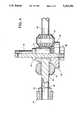
- FIG. 4is a side view in partial cross section of a portion of the differential drive of FIG. 2;
- FIG. 5is a bottom view of the top plate of the motion device of FIG. 2 with the upper links and universal joints removed.
- FIG. 1shows the present invention in an embodiment suitable for use as a robotic end effector for manufacturing or for use as an adaptive fixturing device or for similar applications.
- the end effectorhas a top plate 10 upon which a work piece or tool is typically mounted.
- a set of three legs 12extend from three evenly spaced positions about the bottom of the top plate to a bottom plate 14. While the preferred embodiment is shown and described in terms of top and bottom for convenience, the invention can be operated in any orientation.
- the bottom platesupports each of the legs which in turn support the top plate.
- Each leghas an elbow 16 preferably approximately half way between the top plate and the bottom plate. As will be described in more detail below, each elbow can bend either toward or away from the elbows of the other legs.
- the bottom plateis supported by a set of six support pillars 18 to a base plate 20.
- the base plateis typically mounted to some sort of movable apparatus to which the end effector is connected.
- Three pairs of motor assemblies 22are fastened to the bottom plate and extend downward from the bottom plate.
- Each motor assemblypreferably includes an electromagnetic servo motor, a harmonic drive gear reduction unit which couples the motor to a differential drive mechanism and an encoder which detects the position of the motor rotor.
- the position informationis transmitted to an electronic controller (not shown) for controlling the position and movement of the motors and thereby the top plate of the end effector.
- each motor rotorconnects to a conventional harmonic drive gear reduction unit 24 which connects to a beveled drive gear 28.
- the positions of the two drive gears for each legdetermine the position of the leg of the end effector. Accordingly, the encoders 26 at the base of the motor assemblies, by reading the position of the rotor, can determine precisely the position of the top plate 10.
- Each bevel drive gearis coupled to a double bevel transfer gear 30. It is preferred that, as shown in FIG. 2, the drive gears rotate about a vertical axis to drive the transfer gears which rotate about a horizontal axis. Throughout the application elements will be referred to as being horizontal or vertical. These references refer to the relative orientations as shown in the drawings.
- the motion devicecan be operated in any desired orientation.
- the transfer gear axis of rotationis supplied by a horizontal axle 32 which is mounted at both ends to rigid side walls 34 which are in turn connected by screws 36 and pins 38 into the bottom plate.
- the transfer gearsthrough teeth opposite the teeth that engage the drive gears, drive a link gear 40 which is rigidly fastened to the end of the leg 12.
- Each leghas a lower link 42 which extends through a bore 44 in the horizontal differential axle to the link gear 40.
- the lower link of the legcouples to a clevis 46.
- the clevisis U-shaped with the open side of the U being constructed to match the outer width of the lower link of the leg.
- a horizontal bore drilled through each side of the U and through the lower link of the legreceives a pin 48 and establishes an axis of rotation to form the elbow 16 between the lower link and an upper link 50 which forms the opposite top end of the leg 12.
- the clevisrotates about the elbow pin 48 which is held in place by a drill pin 52 which extends perpendicularly through the lower link and the elbow pin.
- the clevishas a central vertical bore 54 which runs through the base of the U.
- the upper linkis elongated and fits on top of the closed end of the U and has a central bore parallel to its axis of elongation that coincides with the bore in the bottom of the U of the clevis.
- a shoulder pin 56extends from the closed end of the U through the bore in the clevis and the bore in the upper link.
- the pinhas a head which fits against the surface of the closed end of the U to hold it against the U.
- a drill pin 58 through the upper link and the shoulder pinretains the shoulder pin in place.
- the shoulder pinallows the clevis to rotate about the axis of the shoulder pin perpendicular to the axis of the elbow pin.
- the upper linkextends from the clevis away from the base plate and is attached to the top plate 10 with a two degree freedom joint.
- the two degree of freedom universal joint in the top plate for each legis set into a recess 60 in the top plate. There is one recess for each universal joint as shown in FIG. 5.
- a horizontal universal shaft 62is held into the recess with a pivot pin 64 at either end of a vertical wall 63 in the recess 60. These pins allow the horizontal shaft to rotate about a horizontal axis.
- One of each of the other two pairs of pins 66 that hold the horizontal universal shafts for the other two legsare also visible in FIG. 2.
- drill pins 68are used to hold the pins in place. The drill pins extend perpendicular to the axis of the pivot pins.
- the horizontal shafthas an elongated slot 70 (shown in hidden lines in FIG.
- each leg of the motion devicehas a pair of motors which drive gears which, through double bevel transfer gears, operate a link gear at the base of a lower link of each leg.
- This legrotates about a vertical axis and about a horizontal axis i.e. about a pitch axis and a roll axis.
- the lower link of the legis coupled to an upper link by an elbow formed by the clevis and the clevis pin.
- This elbowpreferably rotates about a pitch axis.
- This axisis perpendicular to the roll axis of the differential drive. By pitch, rotation about an axis tangential to a base circle is meant.
- the base circleis a circle with a center at the center of the bottom plate and a radius equal to the distance from the bottom plate to the axis of the pitch joint.
- rollrotation about a member's axis of elongation is meant.
- the upper linkconnects to the clevis with a joint that rotates about a vertical axis, a roll joint, and the end of the upper link has a universal joint connection to the top link which rotates about two perpendicular horizontal axes. Accordingly, beginning at the base plate, there is a pitch-roll two degrees of freedom joint through the differential drive, a pitch joint at the elbow, and a three degrees of freedom joint connection to the top plate. Each of the three axes of the top plate connection joint are perpendicular to each other.
- gears, links and pinsall be fabricated from a high strength stainless steel and that all moving parts be lubricated as is known in the art.
- the clevis 46 and universal shaft 62are preferably made from aluminum to minimize friction against the shoulder pin and the upper link.
- the construction of the bottom plateis shown from the top with the motors removed in FIG. 3.
- the bottom plateis preferably round with pairs of motor mounts 74 evenly spaced around the plate. There is a pair 74-1, 74-2, 74-3 of motor mounts for each of the three legs. In between each motor mount pair is a recess 76 which provides clearance for the bottom of the lower link. A second set of recesses in between each pair of motor mounts 78 provides a mounting surface for the walls 34 which support the differential drive mechanism.
- the bottom plate shown in FIG. 1includes cover plates not shown in FIGS. 2 and 3.
- the walls 34which are fastened to the recesses beside each pair of motor mounts supports the horizontal axes or differential centers 32.
- the differential centersare mounted to the side walls 34 preferably in bronze bearings 80 although ball bearings may also be used.
- the bronze bearingsreceive opposite ends of the differential center 32 and rotatably support this center in the walls.
- the differential centeris an elongated shaft that extends from one side wall to the other and has a central bore 44.
- the lower linkis supported in this bore so that it rotates with respect to the bore in a second set of bronze bearings 82.
- the bronze bearings at either end of the differential center and in the central bore of the differential centerallow the lower link 42 to have both roll and pitch degrees of freedom.
- the double bevel transfer gears 30are placed around the ends of the differential center 32 and allowed to rotate with respect to the differential center by another set of bronze bearings 84 in the central bores of the transfer gears.
- the differential driveis assembled by first inserting the lower link 42 into the bronze bearings 82 in the bore 44 of the differential center.
- the lower link gear 40is then inserted over the outside end of the lower link and held in place by a hex nut 86 at the extreme lower end of the lower link.
- a set screw 88prevents the hex nut from rotating thereby preventing the lower link gear from becoming unscrewed from the end of the lower link.
- the transfer gears 30then each slide over one end of the differential center on their own bronze bearings to a position where they engage the teeth of the lower link gear. Then a snap ring 90 is snapped into grooves at either end of the differential center.
- the bronze bearings for the ends of the differential center 80are inserted into the mounting holes in the side walls 34 and the ends of the differential center are inserted into the side wall bearings 80.
- the whole assembly, with side walls, differential center and lower linkis then lowered into place in the bottom plate and the rigid side walls are screwed into the bottom plate using screws 36.
- the drive gears 28 at the ends of the motor assembliesengage the double bevel transfer gears as the differential drive is lowered into place on the bottom plate.
- the transfer gearsare held in place by the lower link gear on one side and the drive gears on the other side so that the beveled rows of teeth on the two sides of each double beveled gear engage the drive gear and each lower link gear respectively.
- the hex nut 86butts against the link gear and determines the vertical position of the link gear on the lower link.
- the hex nutcan be tightened against the link gear in order to eliminate any backlash or free play in the drive mechanism. Tightening the hex nut pushes the link gear against the transfer gears which slide outwardly against the drive gears until any undesired backlash or free play is eliminated.
- the set screwis then tightened to secure the hex nut in place. After the adjustment, the hex nut prevents the link gear from moving downward and the transfer gears prevent the link gear from moving upward.
- the top plateis shown in greater detail in FIG. 5 with the horizontal universal joint shafts 62 installed using the pivot pins 64 as shown in FIG. 5.
- the top platehas recesses evenly spaced around the circular top plate so that the three legs attach at points evenly spaced around the circular top plate.
- the horizontal universal joint shaftsfit into a recess 60 and the pivot pins are installed through recesses on either side of the central recess 60.
- the position of the top platecan be very precisely controlled by actuating the motors 22.
- Each motordrives a separate drive gear which, in conjunction with the other motor of the motor pair for each leg, precisely controls the movement of each leg.
- the encodersdetermine the position of the rotor shafts of each motor and preferably relay this information to a central controller which determines, by manipulation of the motors, the position of the top plate. Because all of the motors are fastened to the fixed bottom plate and not to the moving top plate, the top plate of end effector has very low inertia and can be moved quickly and easily.
- the present inventionmay be particularly well suited to implementing variable active compliance end effector systems. A variety of different mechanical impedances and damping effects can be produced using techniques known in the art. Unlike other three leg actuators, the top plate of the present invention has a full six degrees of freedom and a very wide range of motion.
- the kinematic arrangementis well suited for a variety of different applications. These applications include positioning fixtures in which an object located on the top plate can be precisely positioned by operating the motors and flight simulators in which a simulated cockpit can be placed on the top plate and moved about by the motors.
- a virtual reality hand controllercan be constructed by placing a handle on the top plate using the motors to generate forces and torques to simulate contact with a real object.
Landscapes
- Engineering & Computer Science (AREA)
- Theoretical Computer Science (AREA)
- Physics & Mathematics (AREA)
- General Physics & Mathematics (AREA)
- Aviation & Aerospace Engineering (AREA)
- Business, Economics & Management (AREA)
- Educational Administration (AREA)
- Educational Technology (AREA)
- Robotics (AREA)
- Mechanical Engineering (AREA)
- Automation & Control Theory (AREA)
- Manipulator (AREA)
Abstract
Description
Claims (36)
Priority Applications (3)
| Application Number | Priority Date | Filing Date | Title |
|---|---|---|---|
| US07/870,121US5263382A (en) | 1992-04-13 | 1992-04-13 | Six Degrees of freedom motion device |
| PCT/US1993/003452WO1993020982A1 (en) | 1992-04-13 | 1993-04-12 | Six degree of freedom motion device |
| AU42842/93AAU4284293A (en) | 1992-04-13 | 1993-04-12 | Six degree of freedom motion device |
Applications Claiming Priority (1)
| Application Number | Priority Date | Filing Date | Title |
|---|---|---|---|
| US07/870,121US5263382A (en) | 1992-04-13 | 1992-04-13 | Six Degrees of freedom motion device |
Publications (1)
| Publication Number | Publication Date |
|---|---|
| US5263382Atrue US5263382A (en) | 1993-11-23 |
Family
ID=25354824
Family Applications (1)
| Application Number | Title | Priority Date | Filing Date |
|---|---|---|---|
| US07/870,121Expired - Fee RelatedUS5263382A (en) | 1992-04-13 | 1992-04-13 | Six Degrees of freedom motion device |
Country Status (3)
| Country | Link |
|---|---|
| US (1) | US5263382A (en) |
| AU (1) | AU4284293A (en) |
| WO (1) | WO1993020982A1 (en) |
Cited By (58)
| Publication number | Priority date | Publication date | Assignee | Title |
|---|---|---|---|---|
| US5524188A (en)* | 1993-03-01 | 1996-06-04 | Halpern Software, Inc. | Viewing three dimensional objects by rotational wobble about multiple axes |
| US5623642A (en)* | 1994-04-06 | 1997-04-22 | M ak Technologies, Inc. | Method for simulating newtonian interactions over a computer network |
| US5673804A (en)* | 1996-12-20 | 1997-10-07 | Pri Automation, Inc. | Hoist system having triangular tension members |
| US5755645A (en)* | 1997-01-09 | 1998-05-26 | Boston Biomotion, Inc. | Exercise apparatus |
| WO1998030366A1 (en)* | 1997-01-14 | 1998-07-16 | Asea Brown Boveri Ab | A device for relative displacement of two elements |
| US5850759A (en)* | 1995-12-29 | 1998-12-22 | Daewoo Electronics Co., Ltd. | Force feed back manipulator with six degrees of freedom |
| US5901936A (en)* | 1997-08-25 | 1999-05-11 | Sandia Corporation | Six-degree-of-freedom multi-axes positioning apparatus |
| US6047610A (en)* | 1997-04-18 | 2000-04-11 | Stocco; Leo J | Hybrid serial/parallel manipulator |
| US6337547B1 (en)* | 1998-08-19 | 2002-01-08 | Commissariat A L'energie Atomique | Linking element with screw jack and its use for an industrial robot arm |
| US6501459B1 (en)* | 1999-02-19 | 2002-12-31 | Alps Electric Co., Ltd. | Input device for game machine, and method of controlling position of controller thereof |
| US6543740B2 (en) | 2001-09-04 | 2003-04-08 | National Research Council Of Canada | Mechanism for transmitting movement in up to six degrees-of-freedom |
| US6681880B2 (en)* | 2000-10-20 | 2004-01-27 | Deere & Company | Control lever |
| US20050275367A1 (en)* | 2004-06-09 | 2005-12-15 | Martin Buehler | Robot and robot leg mechanism |
| US20100259057A1 (en)* | 2009-04-09 | 2010-10-14 | Disney Enterprises, Inc. | Robot hand with human-like fingers |
| US7849762B2 (en) | 2007-12-19 | 2010-12-14 | Robert J Viola | Constrained tri-sphere kinematic positioning system |
| WO2011071450A1 (en)* | 2009-12-11 | 2011-06-16 | Tetrafix Ab | Connecting device for the connection of sections/girders/arms to an attachment |
| CN102289965A (en)* | 2011-09-02 | 2011-12-21 | 浙江大学 | Vehicle driving simulator with heavy-load wideband response |
| US20120048156A1 (en)* | 2010-08-31 | 2012-03-01 | Hon Hai Precision Industry Co., Ltd. | Mobile platform with six degrees of freedom |
| WO2013191773A1 (en)* | 2012-06-22 | 2013-12-27 | Board Of Regents Of The University Of Nebraska | Local Control Robotic Surgical Devices and Related Methods |
| US8679096B2 (en) | 2007-06-21 | 2014-03-25 | Board Of Regents Of The University Of Nebraska | Multifunctional operational component for robotic devices |
| US8761927B2 (en) | 2010-12-17 | 2014-06-24 | Disney Enterprises, Inc. | Externally actuated figure |
| US8828024B2 (en) | 2007-07-12 | 2014-09-09 | Board Of Regents Of The University Of Nebraska | Methods, systems, and devices for surgical access and procedures |
| US8834488B2 (en) | 2006-06-22 | 2014-09-16 | Board Of Regents Of The University Of Nebraska | Magnetically coupleable robotic surgical devices and related methods |
| US8852010B2 (en) | 2011-08-16 | 2014-10-07 | Baylor University | Six-degree-of-freedom cam-controlled support platform |
| US8894633B2 (en) | 2009-12-17 | 2014-11-25 | Board Of Regents Of The University Of Nebraska | Modular and cooperative medical devices and related systems and methods |
| CN104240548A (en)* | 2014-09-04 | 2014-12-24 | 燕山大学 | Six-degree-of-freedom motion simulation platform with three composite drive branched chains |
| US8968267B2 (en) | 2010-08-06 | 2015-03-03 | Board Of Regents Of The University Of Nebraska | Methods and systems for handling or delivering materials for natural orifice surgery |
| US8974440B2 (en) | 2007-08-15 | 2015-03-10 | Board Of Regents Of The University Of Nebraska | Modular and cooperative medical devices and related systems and methods |
| US9060781B2 (en) | 2011-06-10 | 2015-06-23 | Board Of Regents Of The University Of Nebraska | Methods, systems, and devices relating to surgical end effectors |
| US9089353B2 (en) | 2011-07-11 | 2015-07-28 | Board Of Regents Of The University Of Nebraska | Robotic surgical devices, systems, and related methods |
| US9360093B2 (en) | 2011-08-16 | 2016-06-07 | Baylor University | Six-degree-of-freedom cam-controlled support platform |
| US9403281B2 (en) | 2003-07-08 | 2016-08-02 | Board Of Regents Of The University Of Nebraska | Robotic devices with arms and related methods |
| US9498292B2 (en) | 2012-05-01 | 2016-11-22 | Board Of Regents Of The University Of Nebraska | Single site robotic device and related systems and methods |
| US9579088B2 (en) | 2007-02-20 | 2017-02-28 | Board Of Regents Of The University Of Nebraska | Methods, systems, and devices for surgical visualization and device manipulation |
| CN107065113A (en)* | 2017-05-18 | 2017-08-18 | 中国科学院长春光学精密机械与物理研究所 | High-precision six-freedom degree optical module pose adjusting apparatus |
| US9743987B2 (en) | 2013-03-14 | 2017-08-29 | Board Of Regents Of The University Of Nebraska | Methods, systems, and devices relating to robotic surgical devices, end effectors, and controllers |
| US9770305B2 (en) | 2012-08-08 | 2017-09-26 | Board Of Regents Of The University Of Nebraska | Robotic surgical devices, systems, and related methods |
| US9888966B2 (en) | 2013-03-14 | 2018-02-13 | Board Of Regents Of The University Of Nebraska | Methods, systems, and devices relating to force control surgical systems |
| US20190008314A1 (en)* | 2013-11-29 | 2019-01-10 | Steiner Ag Weggis | Device for pouring out milk froth, liquids or the like |
| US10335024B2 (en) | 2007-08-15 | 2019-07-02 | Board Of Regents Of The University Of Nebraska | Medical inflation, attachment and delivery devices and related methods |
| US10342561B2 (en) | 2014-09-12 | 2019-07-09 | Board Of Regents Of The University Of Nebraska | Quick-release end effectors and related systems and methods |
| US10376322B2 (en) | 2014-11-11 | 2019-08-13 | Board Of Regents Of The University Of Nebraska | Robotic device with compact joint design and related systems and methods |
| US10582973B2 (en) | 2012-08-08 | 2020-03-10 | Virtual Incision Corporation | Robotic surgical devices, systems, and related methods |
| US10667883B2 (en) | 2013-03-15 | 2020-06-02 | Virtual Incision Corporation | Robotic surgical devices, systems, and related methods |
| US10806538B2 (en) | 2015-08-03 | 2020-10-20 | Virtual Incision Corporation | Robotic surgical devices, systems, and related methods |
| US10966700B2 (en) | 2013-07-17 | 2021-04-06 | Virtual Incision Corporation | Robotic surgical devices, systems and related methods |
| US10996561B2 (en) | 2017-12-26 | 2021-05-04 | Canon Kabushiki Kaisha | Nanoimprint lithography with a six degrees-of-freedom imprint head module |
| US11786334B2 (en) | 2016-12-14 | 2023-10-17 | Virtual Incision Corporation | Releasable attachment device for coupling to medical devices and related systems and methods |
| US11826014B2 (en) | 2016-05-18 | 2023-11-28 | Virtual Incision Corporation | Robotic surgical devices, systems and related methods |
| US11883065B2 (en) | 2012-01-10 | 2024-01-30 | Board Of Regents Of The University Of Nebraska | Methods, systems, and devices for surgical access and insertion |
| US11903658B2 (en) | 2019-01-07 | 2024-02-20 | Virtual Incision Corporation | Robotically assisted surgical system and related devices and methods |
| US11950867B2 (en) | 2018-01-05 | 2024-04-09 | Board Of Regents Of The University Of Nebraska | Single-arm robotic device with compact joint design and related systems and methods |
| US11974824B2 (en) | 2017-09-27 | 2024-05-07 | Virtual Incision Corporation | Robotic surgical devices with tracking camera technology and related systems and methods |
| US12109079B2 (en) | 2016-11-22 | 2024-10-08 | Board Of Regents Of The University Of Nebraska | Gross positioning device and related systems and methods |
| US12150722B2 (en) | 2020-07-06 | 2024-11-26 | Virtual Incision Corporation | Surgical robot positioning system and related devices and methods |
| US12156710B2 (en) | 2011-10-03 | 2024-12-03 | Virtual Incision Corporation | Robotic surgical devices, systems and related methods |
| US12274517B2 (en) | 2016-08-30 | 2025-04-15 | Board Of Regents Of The University Of Nebraska | Robotic device with compact joint design and an additional degree of freedom and related systems and methods |
| US12295680B2 (en) | 2012-08-08 | 2025-05-13 | Board Of Regents Of The University Of Nebraska | Robotic surgical devices, systems and related methods |
Families Citing this family (2)
| Publication number | Priority date | Publication date | Assignee | Title |
|---|---|---|---|---|
| FR2737432B1 (en)* | 1995-08-04 | 1997-10-10 | Onera (Off Nat Aerospatiale) | TRANSLATION DEVICE WITH PARALLEL STRUCTURE |
| JP3241027U (en)* | 2020-12-22 | 2023-02-24 | 辰星(天津)自動化設備有限公司 | Movable platform for 6-axis robot and 6-axis robot |
Citations (7)
| Publication number | Priority date | Publication date | Assignee | Title |
|---|---|---|---|---|
| US4666362A (en)* | 1985-05-07 | 1987-05-19 | Massachusetts Institute Of Technology | Parallel link manipulators |
| US4806068A (en)* | 1986-09-30 | 1989-02-21 | Dilip Kohli | Rotary linear actuator for use in robotic manipulators |
| US4819496A (en)* | 1987-11-17 | 1989-04-11 | The United States Of America As Represented By The Secretary Of The Air Force | Six degrees of freedom micromanipulator |
| US4919382A (en)* | 1988-09-14 | 1990-04-24 | The United States Of America As Represented By The Secretary Of The Navy | Multi-post yoke gimbal |
| US4976582A (en)* | 1985-12-16 | 1990-12-11 | Sogeva S.A. | Device for the movement and positioning of an element in space |
| US4988244A (en)* | 1989-09-01 | 1991-01-29 | Kearney & Trecker | Six-axis machine tool |
| US5053687A (en)* | 1988-03-21 | 1991-10-01 | Inria Institut National De Recherche En Information Et En Automotique | Articulated device, for use in particular in robotics |
Family Cites Families (3)
| Publication number | Priority date | Publication date | Assignee | Title |
|---|---|---|---|---|
| US2286571A (en)* | 1938-04-22 | 1942-06-16 | Willard L V Pollard | Position-controlling apparatus |
| GB2145691B (en)* | 1983-08-29 | 1987-06-03 | Toshiba Kk | Extendible and contractable arms |
| GB8505746D0 (en)* | 1985-03-06 | 1985-04-11 | Universal Machine Intelligence | Robotic wrist & gripper |
- 1992
- 1992-04-13USUS07/870,121patent/US5263382A/ennot_activeExpired - Fee Related
- 1993
- 1993-04-12WOPCT/US1993/003452patent/WO1993020982A1/enactiveApplication Filing
- 1993-04-12AUAU42842/93Apatent/AU4284293A/ennot_activeAbandoned
Patent Citations (7)
| Publication number | Priority date | Publication date | Assignee | Title |
|---|---|---|---|---|
| US4666362A (en)* | 1985-05-07 | 1987-05-19 | Massachusetts Institute Of Technology | Parallel link manipulators |
| US4976582A (en)* | 1985-12-16 | 1990-12-11 | Sogeva S.A. | Device for the movement and positioning of an element in space |
| US4806068A (en)* | 1986-09-30 | 1989-02-21 | Dilip Kohli | Rotary linear actuator for use in robotic manipulators |
| US4819496A (en)* | 1987-11-17 | 1989-04-11 | The United States Of America As Represented By The Secretary Of The Air Force | Six degrees of freedom micromanipulator |
| US5053687A (en)* | 1988-03-21 | 1991-10-01 | Inria Institut National De Recherche En Information Et En Automotique | Articulated device, for use in particular in robotics |
| US4919382A (en)* | 1988-09-14 | 1990-04-24 | The United States Of America As Represented By The Secretary Of The Navy | Multi-post yoke gimbal |
| US4988244A (en)* | 1989-09-01 | 1991-01-29 | Kearney & Trecker | Six-axis machine tool |
Non-Patent Citations (7)
| Title |
|---|
| A Parallel Robot Arm Regional Structure With Actuational Redundancy by Theodore Kokkinis and Pierre Millies pp. 629 641, 1991.* |
| A Parallel Robot-Arm Regional Structure With Actuational Redundancy by Theodore Kokkinis and Pierre Millies pp. 629-641, 1991. |
| A Platform With Six Degrees of Freedom by D. Stewart vol. 180 Pt 1 No. 15, Proc Instn Mech Engrs 1965 66.* |
| A Platform With Six Degrees of Freedom by D. Stewart vol. 180 Pt 1 No. 15, Proc Instn Mech Engrs 1965-66. |
| HEXA: a fast six DOF fully parallel robot by F. Pierrot, P. Dauchz and A. Fournier, pp. 1158 1163, IEEE, 1991.* |
| HEXA: a fast six-DOF fully-parallel robot by F. Pierrot, P. Dauchz and A. Fournier, pp. 1158-1163, IEEE, 1991. |
| RSI Hand Controller and brochure cover page photographs, Nov. 21, 1991.* |
Cited By (91)
| Publication number | Priority date | Publication date | Assignee | Title |
|---|---|---|---|---|
| US5564000A (en)* | 1993-03-01 | 1996-10-08 | Halpern Software, Inc. | Method and apparatus for viewing three dimensional objects |
| US5524188A (en)* | 1993-03-01 | 1996-06-04 | Halpern Software, Inc. | Viewing three dimensional objects by rotational wobble about multiple axes |
| US5623642A (en)* | 1994-04-06 | 1997-04-22 | M ak Technologies, Inc. | Method for simulating newtonian interactions over a computer network |
| US5850759A (en)* | 1995-12-29 | 1998-12-22 | Daewoo Electronics Co., Ltd. | Force feed back manipulator with six degrees of freedom |
| US5673804A (en)* | 1996-12-20 | 1997-10-07 | Pri Automation, Inc. | Hoist system having triangular tension members |
| US5755645A (en)* | 1997-01-09 | 1998-05-26 | Boston Biomotion, Inc. | Exercise apparatus |
| US6540471B1 (en) | 1997-01-14 | 2003-04-01 | Abb Ab | Device for relative displacement of two elements |
| WO1998030366A1 (en)* | 1997-01-14 | 1998-07-16 | Asea Brown Boveri Ab | A device for relative displacement of two elements |
| US6047610A (en)* | 1997-04-18 | 2000-04-11 | Stocco; Leo J | Hybrid serial/parallel manipulator |
| US5901936A (en)* | 1997-08-25 | 1999-05-11 | Sandia Corporation | Six-degree-of-freedom multi-axes positioning apparatus |
| US6337547B1 (en)* | 1998-08-19 | 2002-01-08 | Commissariat A L'energie Atomique | Linking element with screw jack and its use for an industrial robot arm |
| US6501459B1 (en)* | 1999-02-19 | 2002-12-31 | Alps Electric Co., Ltd. | Input device for game machine, and method of controlling position of controller thereof |
| US6681880B2 (en)* | 2000-10-20 | 2004-01-27 | Deere & Company | Control lever |
| US6543740B2 (en) | 2001-09-04 | 2003-04-08 | National Research Council Of Canada | Mechanism for transmitting movement in up to six degrees-of-freedom |
| US9403281B2 (en) | 2003-07-08 | 2016-08-02 | Board Of Regents Of The University Of Nebraska | Robotic devices with arms and related methods |
| US20050275367A1 (en)* | 2004-06-09 | 2005-12-15 | Martin Buehler | Robot and robot leg mechanism |
| US7734375B2 (en)* | 2004-06-09 | 2010-06-08 | Boston Dynamics | Robot and robot leg mechanism |
| US8834488B2 (en) | 2006-06-22 | 2014-09-16 | Board Of Regents Of The University Of Nebraska | Magnetically coupleable robotic surgical devices and related methods |
| US9883911B2 (en) | 2006-06-22 | 2018-02-06 | Board Of Regents Of The University Of Nebraska | Multifunctional operational component for robotic devices |
| US8968332B2 (en) | 2006-06-22 | 2015-03-03 | Board Of Regents Of The University Of Nebraska | Magnetically coupleable robotic surgical devices and related methods |
| US10307199B2 (en) | 2006-06-22 | 2019-06-04 | Board Of Regents Of The University Of Nebraska | Robotic surgical devices and related methods |
| US9579088B2 (en) | 2007-02-20 | 2017-02-28 | Board Of Regents Of The University Of Nebraska | Methods, systems, and devices for surgical visualization and device manipulation |
| US8679096B2 (en) | 2007-06-21 | 2014-03-25 | Board Of Regents Of The University Of Nebraska | Multifunctional operational component for robotic devices |
| US9179981B2 (en) | 2007-06-21 | 2015-11-10 | Board Of Regents Of The University Of Nebraska | Multifunctional operational component for robotic devices |
| US9956043B2 (en) | 2007-07-12 | 2018-05-01 | Board Of Regents Of The University Of Nebraska | Methods, systems, and devices for surgical access and procedures |
| US8828024B2 (en) | 2007-07-12 | 2014-09-09 | Board Of Regents Of The University Of Nebraska | Methods, systems, and devices for surgical access and procedures |
| US10335024B2 (en) | 2007-08-15 | 2019-07-02 | Board Of Regents Of The University Of Nebraska | Medical inflation, attachment and delivery devices and related methods |
| US8974440B2 (en) | 2007-08-15 | 2015-03-10 | Board Of Regents Of The University Of Nebraska | Modular and cooperative medical devices and related systems and methods |
| US7849762B2 (en) | 2007-12-19 | 2010-12-14 | Robert J Viola | Constrained tri-sphere kinematic positioning system |
| US8052185B2 (en) | 2009-04-09 | 2011-11-08 | Disney Enterprises, Inc. | Robot hand with humanoid fingers |
| US20100259057A1 (en)* | 2009-04-09 | 2010-10-14 | Disney Enterprises, Inc. | Robot hand with human-like fingers |
| WO2011071450A1 (en)* | 2009-12-11 | 2011-06-16 | Tetrafix Ab | Connecting device for the connection of sections/girders/arms to an attachment |
| US8894633B2 (en) | 2009-12-17 | 2014-11-25 | Board Of Regents Of The University Of Nebraska | Modular and cooperative medical devices and related systems and methods |
| US8968267B2 (en) | 2010-08-06 | 2015-03-03 | Board Of Regents Of The University Of Nebraska | Methods and systems for handling or delivering materials for natural orifice surgery |
| US20120048156A1 (en)* | 2010-08-31 | 2012-03-01 | Hon Hai Precision Industry Co., Ltd. | Mobile platform with six degrees of freedom |
| US8505392B2 (en)* | 2010-08-31 | 2013-08-13 | Hong Fu Jin Precision Industry (Shenzhen) Co., Ltd. | Mobile platform with six degrees of freedom |
| US8761927B2 (en) | 2010-12-17 | 2014-06-24 | Disney Enterprises, Inc. | Externally actuated figure |
| US9757187B2 (en) | 2011-06-10 | 2017-09-12 | Board Of Regents Of The University Of Nebraska | Methods, systems, and devices relating to surgical end effectors |
| US11832871B2 (en) | 2011-06-10 | 2023-12-05 | Board Of Regents Of The University Of Nebraska | Methods, systems, and devices relating to surgical end effectors |
| US9060781B2 (en) | 2011-06-10 | 2015-06-23 | Board Of Regents Of The University Of Nebraska | Methods, systems, and devices relating to surgical end effectors |
| US9089353B2 (en) | 2011-07-11 | 2015-07-28 | Board Of Regents Of The University Of Nebraska | Robotic surgical devices, systems, and related methods |
| US12323289B2 (en) | 2011-07-11 | 2025-06-03 | Board Of Regents Of The University Of Nebraska | Robotic surgical devices, systems, and related methods |
| US10111711B2 (en) | 2011-07-11 | 2018-10-30 | Board Of Regents Of The University Of Nebraska | Robotic surgical devices, systems, and related methods |
| US11909576B2 (en) | 2011-07-11 | 2024-02-20 | Board Of Regents Of The University Of Nebraska | Robotic surgical devices, systems, and related methods |
| US9360093B2 (en) | 2011-08-16 | 2016-06-07 | Baylor University | Six-degree-of-freedom cam-controlled support platform |
| US8852010B2 (en) | 2011-08-16 | 2014-10-07 | Baylor University | Six-degree-of-freedom cam-controlled support platform |
| CN102289965A (en)* | 2011-09-02 | 2011-12-21 | 浙江大学 | Vehicle driving simulator with heavy-load wideband response |
| US12156710B2 (en) | 2011-10-03 | 2024-12-03 | Virtual Incision Corporation | Robotic surgical devices, systems and related methods |
| US11883065B2 (en) | 2012-01-10 | 2024-01-30 | Board Of Regents Of The University Of Nebraska | Methods, systems, and devices for surgical access and insertion |
| US12171512B2 (en) | 2012-05-01 | 2024-12-24 | Board Of Regents Of The University Of Nebraska | Single site robotic device and related systems and methods |
| US9498292B2 (en) | 2012-05-01 | 2016-11-22 | Board Of Regents Of The University Of Nebraska | Single site robotic device and related systems and methods |
| US10219870B2 (en) | 2012-05-01 | 2019-03-05 | Board Of Regents Of The University Of Nebraska | Single site robotic device and related systems and methods |
| US11819299B2 (en) | 2012-05-01 | 2023-11-21 | Board Of Regents Of The University Of Nebraska | Single site robotic device and related systems and methods |
| WO2013191773A1 (en)* | 2012-06-22 | 2013-12-27 | Board Of Regents Of The University Of Nebraska | Local Control Robotic Surgical Devices and Related Methods |
| US10470828B2 (en)* | 2012-06-22 | 2019-11-12 | Board Of Regents Of The University Of Nebraska | Local control robotic surgical devices and related methods |
| US9010214B2 (en) | 2012-06-22 | 2015-04-21 | Board Of Regents Of The University Of Nebraska | Local control robotic surgical devices and related methods |
| US9770305B2 (en) | 2012-08-08 | 2017-09-26 | Board Of Regents Of The University Of Nebraska | Robotic surgical devices, systems, and related methods |
| US11832902B2 (en) | 2012-08-08 | 2023-12-05 | Virtual Incision Corporation | Robotic surgical devices, systems, and related methods |
| US10582973B2 (en) | 2012-08-08 | 2020-03-10 | Virtual Incision Corporation | Robotic surgical devices, systems, and related methods |
| US12295680B2 (en) | 2012-08-08 | 2025-05-13 | Board Of Regents Of The University Of Nebraska | Robotic surgical devices, systems and related methods |
| US9888966B2 (en) | 2013-03-14 | 2018-02-13 | Board Of Regents Of The University Of Nebraska | Methods, systems, and devices relating to force control surgical systems |
| US9743987B2 (en) | 2013-03-14 | 2017-08-29 | Board Of Regents Of The University Of Nebraska | Methods, systems, and devices relating to robotic surgical devices, end effectors, and controllers |
| US11806097B2 (en) | 2013-03-14 | 2023-11-07 | Board Of Regents Of The University Of Nebraska | Methods, systems, and devices relating to robotic surgical devices, end effectors, and controllers |
| US12070282B2 (en) | 2013-03-14 | 2024-08-27 | Board Of Regents Of The University Of Nebraska | Methods, systems, and devices relating to force control surgical systems |
| US12336777B2 (en) | 2013-03-14 | 2025-06-24 | Board Of Regents Of The University Of Nebraska | Methods, systems, and devices relating to robotic surgical devices, end effectors, and controllers |
| US10667883B2 (en) | 2013-03-15 | 2020-06-02 | Virtual Incision Corporation | Robotic surgical devices, systems, and related methods |
| US10966700B2 (en) | 2013-07-17 | 2021-04-06 | Virtual Incision Corporation | Robotic surgical devices, systems and related methods |
| US11826032B2 (en) | 2013-07-17 | 2023-11-28 | Virtual Incision Corporation | Robotic surgical devices, systems and related methods |
| US10980368B2 (en)* | 2013-11-29 | 2021-04-20 | Steiner Ag Weggis | Device for pouring out milk froth, liquids or the like |
| US20190008314A1 (en)* | 2013-11-29 | 2019-01-10 | Steiner Ag Weggis | Device for pouring out milk froth, liquids or the like |
| CN104240548A (en)* | 2014-09-04 | 2014-12-24 | 燕山大学 | Six-degree-of-freedom motion simulation platform with three composite drive branched chains |
| US12390240B2 (en) | 2014-09-12 | 2025-08-19 | Virtual Incision Corporation | Quick-release end effectors and related systems and methods |
| US10342561B2 (en) | 2014-09-12 | 2019-07-09 | Board Of Regents Of The University Of Nebraska | Quick-release end effectors and related systems and methods |
| US12096999B2 (en) | 2014-11-11 | 2024-09-24 | Board Of Regents Of The University Of Nebraska | Robotic device with compact joint design and related systems and methods |
| US10376322B2 (en) | 2014-11-11 | 2019-08-13 | Board Of Regents Of The University Of Nebraska | Robotic device with compact joint design and related systems and methods |
| US11872090B2 (en) | 2015-08-03 | 2024-01-16 | Virtual Incision Corporation | Robotic surgical devices, systems, and related methods |
| US10806538B2 (en) | 2015-08-03 | 2020-10-20 | Virtual Incision Corporation | Robotic surgical devices, systems, and related methods |
| US12383355B2 (en) | 2016-05-18 | 2025-08-12 | Virtual Incision Corporation | Robotic surgical devices, systems and related methods |
| US11826014B2 (en) | 2016-05-18 | 2023-11-28 | Virtual Incision Corporation | Robotic surgical devices, systems and related methods |
| US12274517B2 (en) | 2016-08-30 | 2025-04-15 | Board Of Regents Of The University Of Nebraska | Robotic device with compact joint design and an additional degree of freedom and related systems and methods |
| US12109079B2 (en) | 2016-11-22 | 2024-10-08 | Board Of Regents Of The University Of Nebraska | Gross positioning device and related systems and methods |
| US11786334B2 (en) | 2016-12-14 | 2023-10-17 | Virtual Incision Corporation | Releasable attachment device for coupling to medical devices and related systems and methods |
| CN107065113A (en)* | 2017-05-18 | 2017-08-18 | 中国科学院长春光学精密机械与物理研究所 | High-precision six-freedom degree optical module pose adjusting apparatus |
| CN107065113B (en)* | 2017-05-18 | 2019-06-11 | 中国科学院长春光学精密机械与物理研究所 | High-precision six-degree-of-freedom optical component pose adjustment device |
| US11974824B2 (en) | 2017-09-27 | 2024-05-07 | Virtual Incision Corporation | Robotic surgical devices with tracking camera technology and related systems and methods |
| US12343098B2 (en) | 2017-09-27 | 2025-07-01 | Virtual Incision Corporation | Robotic surgical devices with tracking camera technology and related systems and methods |
| US10996561B2 (en) | 2017-12-26 | 2021-05-04 | Canon Kabushiki Kaisha | Nanoimprint lithography with a six degrees-of-freedom imprint head module |
| US12303221B2 (en) | 2018-01-05 | 2025-05-20 | Board Of Regents Of The University Of Nebraska | Single-arm robotic device with compact joint design and related systems and methods |
| US11950867B2 (en) | 2018-01-05 | 2024-04-09 | Board Of Regents Of The University Of Nebraska | Single-arm robotic device with compact joint design and related systems and methods |
| US11903658B2 (en) | 2019-01-07 | 2024-02-20 | Virtual Incision Corporation | Robotically assisted surgical system and related devices and methods |
| US12150722B2 (en) | 2020-07-06 | 2024-11-26 | Virtual Incision Corporation | Surgical robot positioning system and related devices and methods |
Also Published As
| Publication number | Publication date |
|---|---|
| AU4284293A (en) | 1993-11-18 |
| WO1993020982A1 (en) | 1993-10-28 |
Similar Documents
| Publication | Publication Date | Title |
|---|---|---|
| US5263382A (en) | Six Degrees of freedom motion device | |
| US5533418A (en) | Spherical robotic shoulder joint | |
| US8215199B2 (en) | Parallel kinematic positioning system | |
| EP0188863B1 (en) | Direct drive robotic system | |
| US7337691B2 (en) | Parallel kinematics mechanism with a concentric spherical joint | |
| US8251863B2 (en) | Continuously variable transmission with multiple outputs | |
| US5197846A (en) | Six-degree-of-freedom articulated robot mechanism and assembling and working apparatus using same | |
| US7478576B2 (en) | Robotic manipulator | |
| US5811951A (en) | High precision redundant robotic manipulator | |
| US4807486A (en) | Three-axes wrist mechanism | |
| JPH02504244A (en) | Joint device used in robots | |
| US20050262959A1 (en) | Four-degree-of-freedom parallel manipulator for producing schonflies motions | |
| CA2045487A1 (en) | Robotic manipulator | |
| EP1075360B1 (en) | A device for relative movement of two elements | |
| GB2083795A (en) | Manipulator mechanisms | |
| JPH0351710A (en) | Gimbal module | |
| WO2012104785A1 (en) | Drive apparatus | |
| US6038940A (en) | Controlled robotic carrier | |
| US20040013509A1 (en) | Parallel kinematics mechanism with a concentric spherical joint | |
| EP1178875A1 (en) | Manipulator | |
| JPS63163063A (en) | 2-degree-of-freedom drive mechanism for industrial robot wrist | |
| Fisher et al. | Design of a reconfigurable planar parallel manipulator | |
| CN205971578U (en) | Remote -controlled robot | |
| EP1513657B1 (en) | An industrial robot and a method for manipulation in an industrial robot comprising a parallel kinematic manipulator | |
| JPH02232193A (en) | Balance device for articulated robots |
Legal Events
| Date | Code | Title | Description |
|---|---|---|---|
| AS | Assignment | Owner name:HUGHES AIRCRAFT COMPANY, A DE CORP. Free format text:ASSIGNMENT OF ASSIGNORS INTEREST.;ASSIGNORS:BROOKS, THURSTON L.;CLEARY, KEVIN R.;UEBEL, MARK;REEL/FRAME:006173/0047 Effective date:19920619 | |
| CC | Certificate of correction | ||
| FEPP | Fee payment procedure | Free format text:PAYOR NUMBER ASSIGNED (ORIGINAL EVENT CODE: ASPN); ENTITY STATUS OF PATENT OWNER: LARGE ENTITY | |
| FPAY | Fee payment | Year of fee payment:4 | |
| FPAY | Fee payment | Year of fee payment:8 | |
| AS | Assignment | Owner name:HE HOLDINGS, INC., A DELAWARE CORP., CALIFORNIA Free format text:CHANGE OF NAME;ASSIGNOR:HUGHES AIRCRAFT COMPANY, A CORPORATION OF THE STATE OF DELAWARE;REEL/FRAME:016087/0541 Effective date:19971217 Owner name:RAYTHEON COMPANY, MASSACHUSETTS Free format text:MERGER;ASSIGNOR:HE HOLDINGS, INC. DBA HUGHES ELECTRONICS;REEL/FRAME:016116/0506 Effective date:19971217 | |
| REMI | Maintenance fee reminder mailed | ||
| LAPS | Lapse for failure to pay maintenance fees | ||
| STCH | Information on status: patent discontinuation | Free format text:PATENT EXPIRED DUE TO NONPAYMENT OF MAINTENANCE FEES UNDER 37 CFR 1.362 | |
| FP | Lapsed due to failure to pay maintenance fee | Effective date:20051123 |