US5262121A - Method of making and using flexible mandrel - Google Patents
Method of making and using flexible mandrelDownload PDFInfo
- Publication number
- US5262121A US5262121AUS07/809,757US80975791AUS5262121AUS 5262121 AUS5262121 AUS 5262121AUS 80975791 AUS80975791 AUS 80975791AUS 5262121 AUS5262121 AUS 5262121A
- Authority
- US
- United States
- Prior art keywords
- mandrel
- mold
- media
- providing
- vacuum
- Prior art date
- Legal status (The legal status is an assumption and is not a legal conclusion. Google has not performed a legal analysis and makes no representation as to the accuracy of the status listed.)
- Expired - Lifetime
Links
Images


Classifications
- B—PERFORMING OPERATIONS; TRANSPORTING
- B29—WORKING OF PLASTICS; WORKING OF SUBSTANCES IN A PLASTIC STATE IN GENERAL
- B29D—PRODUCING PARTICULAR ARTICLES FROM PLASTICS OR FROM SUBSTANCES IN A PLASTIC STATE
- B29D23/00—Producing tubular articles
- B29D23/001—Pipes; Pipe joints
- B29D23/003—Pipe joints, e.g. straight joints
- B29D23/008—T-joints
- B—PERFORMING OPERATIONS; TRANSPORTING
- B29—WORKING OF PLASTICS; WORKING OF SUBSTANCES IN A PLASTIC STATE IN GENERAL
- B29C—SHAPING OR JOINING OF PLASTICS; SHAPING OF MATERIAL IN A PLASTIC STATE, NOT OTHERWISE PROVIDED FOR; AFTER-TREATMENT OF THE SHAPED PRODUCTS, e.g. REPAIRING
- B29C33/00—Moulds or cores; Details thereof or accessories therefor
- B29C33/38—Moulds or cores; Details thereof or accessories therefor characterised by the material or the manufacturing process
- B29C33/3821—Moulds or cores; Details thereof or accessories therefor characterised by the material or the manufacturing process composed of particles enclosed in a bag
- B—PERFORMING OPERATIONS; TRANSPORTING
- B29—WORKING OF PLASTICS; WORKING OF SUBSTANCES IN A PLASTIC STATE IN GENERAL
- B29C—SHAPING OR JOINING OF PLASTICS; SHAPING OF MATERIAL IN A PLASTIC STATE, NOT OTHERWISE PROVIDED FOR; AFTER-TREATMENT OF THE SHAPED PRODUCTS, e.g. REPAIRING
- B29C33/00—Moulds or cores; Details thereof or accessories therefor
- B29C33/38—Moulds or cores; Details thereof or accessories therefor characterised by the material or the manufacturing process
- B29C33/3842—Manufacturing moulds, e.g. shaping the mould surface by machining
- B29C33/3857—Manufacturing moulds, e.g. shaping the mould surface by machining by making impressions of one or more parts of models, e.g. shaped articles and including possible subsequent assembly of the parts
- B—PERFORMING OPERATIONS; TRANSPORTING
- B29—WORKING OF PLASTICS; WORKING OF SUBSTANCES IN A PLASTIC STATE IN GENERAL
- B29C—SHAPING OR JOINING OF PLASTICS; SHAPING OF MATERIAL IN A PLASTIC STATE, NOT OTHERWISE PROVIDED FOR; AFTER-TREATMENT OF THE SHAPED PRODUCTS, e.g. REPAIRING
- B29C33/00—Moulds or cores; Details thereof or accessories therefor
- B29C33/44—Moulds or cores; Details thereof or accessories therefor with means for, or specially constructed to facilitate, the removal of articles, e.g. of undercut articles
- B29C33/48—Moulds or cores; Details thereof or accessories therefor with means for, or specially constructed to facilitate, the removal of articles, e.g. of undercut articles with means for collapsing or disassembling
- B29C33/50—Moulds or cores; Details thereof or accessories therefor with means for, or specially constructed to facilitate, the removal of articles, e.g. of undercut articles with means for collapsing or disassembling elastic or flexible
- B29C33/505—Moulds or cores; Details thereof or accessories therefor with means for, or specially constructed to facilitate, the removal of articles, e.g. of undercut articles with means for collapsing or disassembling elastic or flexible cores or mandrels, e.g. inflatable
- B—PERFORMING OPERATIONS; TRANSPORTING
- B29—WORKING OF PLASTICS; WORKING OF SUBSTANCES IN A PLASTIC STATE IN GENERAL
- B29C—SHAPING OR JOINING OF PLASTICS; SHAPING OF MATERIAL IN A PLASTIC STATE, NOT OTHERWISE PROVIDED FOR; AFTER-TREATMENT OF THE SHAPED PRODUCTS, e.g. REPAIRING
- B29C69/00—Combinations of shaping techniques not provided for in a single one of main groups B29C39/00 - B29C67/00, e.g. associations of moulding and joining techniques; Apparatus therefore
- B29C69/004—Combinations of shaping techniques not provided for in a single one of main groups B29C39/00 - B29C67/00, e.g. associations of moulding and joining techniques; Apparatus therefore making articles by joining parts moulded in separate cavities, said parts being in said separate cavities during said joining
- B—PERFORMING OPERATIONS; TRANSPORTING
- B29—WORKING OF PLASTICS; WORKING OF SUBSTANCES IN A PLASTIC STATE IN GENERAL
- B29C—SHAPING OR JOINING OF PLASTICS; SHAPING OF MATERIAL IN A PLASTIC STATE, NOT OTHERWISE PROVIDED FOR; AFTER-TREATMENT OF THE SHAPED PRODUCTS, e.g. REPAIRING
- B29C70/00—Shaping composites, i.e. plastics material comprising reinforcements, fillers or preformed parts, e.g. inserts
- B29C70/04—Shaping composites, i.e. plastics material comprising reinforcements, fillers or preformed parts, e.g. inserts comprising reinforcements only, e.g. self-reinforcing plastics
- B29C70/28—Shaping operations therefor
- B29C70/40—Shaping or impregnating by compression not applied
- B29C70/42—Shaping or impregnating by compression not applied for producing articles of definite length, i.e. discrete articles
- B29C70/44—Shaping or impregnating by compression not applied for producing articles of definite length, i.e. discrete articles using isostatic pressure, e.g. pressure difference-moulding, vacuum bag-moulding, autoclave-moulding or expanding rubber-moulding
- B29C70/446—Moulding structures having an axis of symmetry or at least one channel, e.g. tubular structures, frames
- B—PERFORMING OPERATIONS; TRANSPORTING
- B29—WORKING OF PLASTICS; WORKING OF SUBSTANCES IN A PLASTIC STATE IN GENERAL
- B29K—INDEXING SCHEME ASSOCIATED WITH SUBCLASSES B29B, B29C OR B29D, RELATING TO MOULDING MATERIALS OR TO MATERIALS FOR MOULDS, REINFORCEMENTS, FILLERS OR PREFORMED PARTS, e.g. INSERTS
- B29K2021/00—Use of unspecified rubbers as moulding material
- B—PERFORMING OPERATIONS; TRANSPORTING
- B29—WORKING OF PLASTICS; WORKING OF SUBSTANCES IN A PLASTIC STATE IN GENERAL
- B29K—INDEXING SCHEME ASSOCIATED WITH SUBCLASSES B29B, B29C OR B29D, RELATING TO MOULDING MATERIALS OR TO MATERIALS FOR MOULDS, REINFORCEMENTS, FILLERS OR PREFORMED PARTS, e.g. INSERTS
- B29K2105/00—Condition, form or state of moulded material or of the material to be shaped
- B29K2105/24—Condition, form or state of moulded material or of the material to be shaped crosslinked or vulcanised
- B—PERFORMING OPERATIONS; TRANSPORTING
- B29—WORKING OF PLASTICS; WORKING OF SUBSTANCES IN A PLASTIC STATE IN GENERAL
- B29L—INDEXING SCHEME ASSOCIATED WITH SUBCLASS B29C, RELATING TO PARTICULAR ARTICLES
- B29L2031/00—Other particular articles
- B29L2031/24—Pipe joints or couplings
- B29L2031/246—T-joints
Definitions
- This inventionrelates to a method of making and using a re-usable flexible mandrel which can be made rigid according to the present method for use as a tool for formation of composite parts.
- Composite materialscomprising a fiber-reinforced resin matrix are often used to form lightweight, high strength parts.
- One ideal use of these materialsis for fabrication of structural or non-structural aircraft parts, especially environmental control system ducts.
- Fabrication of environmental control system duct parts made of composite materialstypically includes formation of a mandrel having an exterior shape generally conforming to the desired interior shape of the duct part. Uncured composite materials are then laid up on the mandrel and cured by applying heat and pressure according to well-known methods. Present industry practice is to form expendable mandrels from plaster or water soluble eutectic salts. After the composite part has been cured, the plaster mandrel is removed by breaking it away from the part using impact devices. The broken plaster pieces are then discarded at significant cost to the manufacturer.
- the finished composite partis separated from the mandrel by breaking away the plaster from within the part. This creates a very dusty workplace environment and it is not uncommon that this causes damage to the part which must be repaired. Due to the inherently porous nature and moisture content of the plaster mandrel, the finished part is typically resin sloshed internally to seal and provide a smoother finished surface.
- Expandable elastomeric mandrelshave been used previously in other types of composite part fabrication.
- One such processis the use of an expandable mandrel where pressure is applied to the interior of the mandrel and expanded to force uncured composite material to conform to an interior mold surface of the external part configuration.
- These mandrelsare limited to simple design configurations in which the internal surfaces of the part are not critical.
- An object of the present inventionis to provide a reusable mandrel for forming internally-sized parts, such as ducting, which can be made at a reasonable cost, can be reused many times, produces higher quality composite material products, and produces no waste product for disposal.
- the present inventionprovides a method of making and using a flexible mandrel for use in formation of parts from composite materials.
- the method of making the flexible mandrelincludes the steps of providing a separable mold with an interior chamber shaped to provide a desired exterior mandrel size and shape and applying uncured elastomeric material to surfaces of the interior chamber of separated parts of the mold.
- the elastomeric materialis joined by assembling the mold parts prior to curing such that the material joins at seams.
- the elastomeric materialis allowed to cure into a shape of the desired flexible mandrel.
- a fill openingis provided such that the mandrel is fillable with a flowable particulate solid material and evacuable to compact the particulate material.
- the flexible mandrelmay also include an internal elongated rigid reinforcement means for providing increased longitudinal rigidity and displacing a portion of the fill media.
- the flexible mandrelis formed of a sprayable silicone rubber material and includes flange means for sealing the mandrel at mold openings.
- the mandrelmay also include a combined closure member and evacuation port which is used to close the fill opening and to provide an internal vacuum on the mandrel.
- a reservoirmay be provided which is operably connected with the mandrel so that fill media may be moved between the reservoir and the mandrel without risk of spillage and without repeated measurement of optimal fill media volume.
- the method of using a flexible mandrelincludes the steps of providing a hollow elastomeric mandrel with a predetermined exterior size and shape and with a fill opening and an evacuation port.
- the mandrelis placed in a mold having an interior cavity surface sized and shaped to correspond to a desired exterior size and shape of the mandrel in use.
- An external vacuumis provided within the mold to draw the mandrel snugly against the mold's interior surface.
- the mandrelis then filled with a flowable particulate solid material through the fill opening and an internal vacuum is provided within the mandrel to compact the particulate material into a substantially rigid form.
- the external vacuumis released while maintaining the internal vacuum, and the mandrel is removed from the mold for use.
- the mandrelmay be used by applying uncured composite material on it and curing the composite material in place on the mandrel.
- the mandrelmay be separated from the cured composite part by removing the internal vacuum and displacing at least a portion of the fill media, preferably into an attached reservoir.
- the fill mediais preliminarily compacted by vibrating or shaking the media prior to applying the internal vacuum.
- an elongated rigid reinforcement meansmay be provided within the mandrel such that it displaces a portion of the fill media and provides increased longitudinal rigidity.
- Existing moldsmay be modified for use according to the invention by providing an elastomeric seal means between the mold parts and/or by providing seal flanges on the mandrel at openings of the mold.
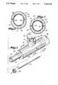
- FIG. 1is a pictorial view of a fiber-reinforced resin matrix composite material part made according to the present invention
- FIG. 2is a mold separated into two parts in which an elastomeric mandrel according to the present invention is formed;
- FIG. 3is a sectional view of a mold to which uncured elastomeric material has been applied for making a flexible mandrel;
- FIG. 4is a sectional view taken substantially along lines 4--4 of FIG. 5, showing separate parts of a flexible mandrel bonded together to cure within the mold;
- FIG. 5is an exploded pictorial view of a flexible mandrel apparatus being made according to the method of the present invention
- FIG. 6is a pictorial view of a flexible mandrel constructed according to the method of the present invention and for use according to the method of the present invention
- FIG. 7is a partially-sectioned view of a fill opening plug with an evacuation port
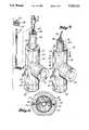
- FIG. 8is an exploded pictorial view of a flexible mandrel being filled according to a preferred method of the present invention.
- FIG. 9is a pictorial view showing the flexible mandrel being evacuated and rigidified into shape according to the preferred method of the present invention.
- FIG. 10is a partial sectional view taken substantially along line 10--10 of FIG. 9 showing the filled and evacuated mandrel being shaped according to the preferred method of the present invention
- FIG. 11is a pictorial view showing the prepared mandrel being laid up with uncured composite material
- FIG. 12is a view similar to FIG. 11, showing the part and mandrel vacuum bagged for heat and pressure curing;
- FIG. 13is a sectional view taken substantially along line 13--13 of FIG. 12. showing the composite material part prepared for curing on the rigidified elastomeric mandrel.
- FIG. 1therein is shown at 10 a typical fiber-reinforced resin matrix composite material part in the form of a ventilation duct which may commonly be used on commercial airplanes.
- the critical dimensioning and surface areais the interior of the hollow part.
- the part shownincludes three branches 12, 14, 16, the latter including a connector sleeve dimensioned to receive an end portion of an adjoining duct part.
- composite materialsare relatively flexible.
- partsare formed by providing a rigid mandrel onto which the composite material is "built up” or layered into a desired shape.
- the composite materialsmay be built up by alternating layers of resins and fibrous sheets, or by applying layers of resin-impregnated fibrous sheets, often referred to as "prepreg.”
- prepreglayers of resin-impregnated fibrous sheets
- fibersmay be wound onto a mandrel in conjunction with the application of resins.
- the composite materialsAfter being laid up on a form, the composite materials are cured by subjecting them to a combination of heat and pressure. Upon being heated, the resinous material initially becomes more fluid and flows to homogeneously surround the reinforcing fibers. Compression of the composite materials as they are curing forces out gas bubbles which may exist in the material and which could create structural flaws. The combination of heat and pressure facilitates cross-linking of the resinous compounds to create a strong, consolidated material.
- mandrelshave been made from plaster or water-soluble eutectic salts. Typically, these are fabricated using multi-piece slosh molds which are constructed to conform to the internal shape of the desired part or duct.
- the re-usable flexible mandrel and method for its use of the present inventioncan make use of existing molds with only minor modifications or attachments.
- FIG. 2therein is shown at 18 and 20 a separable mold of common construction typically used for slosh molding of plaster or eutectic salt mandrels.
- These moldsmay be made from, for example, a fiberglass/epoxy composite.
- the illustrated mold 18, 20need only be separable into two main pieces.
- Such a mold for use in forming the more delicate plaster or eutectic salt mandrels of the illustrated shapewould typically be separable into four or more pieces. The number of pieces in any given mold will depend upon the shape, size and configuration of the mandrel being formed.
- a flexible mandrelwill typically require the mold to be separable into significantly fewer parts than when used to form rigid mandrels.
- interior surfaces 22, 24create a chamber 25 which is shaped to provide a desired exterior mandrel size and shape.
- the flexible mandrel of the present inventionis formed on the interior surfaces 22, 24 of the mold parts 18, 20 which are later assembled to form a unitary, hollow elastomeric mandrel.
- Existing molds for use in slosh molding plaster mandrelscan be used with the method of the present invention with only very minor modification, as explained later.
- the mandrelis made from an elastomeric material, such as a silicone rubber compound.
- the preferred materialis a sprayable, thixotropic silicone designed for use in making seamless spray-on external conformal vacuum bags and is sold under the trade names "DAPCO 63"and “DAPCOCAST 62 HT", by D Aircraft Products, Inc., a subsidiary of American Cyanamid, of Anaheim, CA. This material is sprayable when diluted with solvents according to the manufacturer's specifications and, when properly cured, is very durable, flexible, stable, and heat-resistant.
- This material 27can be painted or, preferably, sprayed onto interior surfaces 22, 24 of the mold parts 18, 20, as shown in FIG. 2.
- the silicone material 27is sprayed in multiple layers, allowing air curing between coats.
- the above-described preferred materialis self-bonding to like material.
- Each layer 27is applied at a preferred thickness of approximately 0.007 to 0.012 inch.
- Overspray or flash areas 26are wiped away immediately to prevent excess buildup of flash between each coat.
- a final thickness of 0.050 to 0.090 inchesis preferred.
- a sufficient number of coatsshould be applied to provide the desired thickness, allowing at least a partial air cure between coats (15-30 minutes). If deemed necessary, points of increased stress or wear could be thickened.
- the joined-together elastomeric mandrel 29is allowed a suitable low temperature air cure before removal from the mold for a free-standing post cure.
- a heated post cure in accordance with the silicone compound manufacturer's recommendationsis preferred.
- ends 31, 33which are normally open are capped or sealed to contain the media which will later be used to fill and hold the mandrel's shape during use.
- cap pieces 30, 32are attached to the open ends 31, 33.
- the end caps 30, 32can be out from a sheet of material, such as cured silicone, having physical properties consistent with the material used to construct the body of the mandrel 29.
- a suitable sheet of materialcan be made by spraying a suitable thickness on a flat surface, then removing and cutting to shape to form the end caps 30, 32.
- the caps 30, 32can be attached after the mandrel 29 has air cured and has been removed from the mold 18, 20, using uncured silicone compound as an adhesive. Or, the cap pieces 30, 32 may be attached immediately after the mold halves 18, 20 are assembled together. If done this way, a narrow ring of uncured flash 34 may be allowed to remain around the perimeter of the open ends 31, 33, which will form an integral seam with the end caps 30, 32.
- blind endscould be provided in the mandrel 29 by constructing a special mold (not shown) which would provide flat or rounded end closures for the mandrel which extend beyond its used areas.
- the mandrel 29is sized to extend slightly beyond the finished trim length of the composite part. These areas, for example, can be seen at 36, 38, 40 in FIG. 6.
- a fill opening 42, 46is provided for the introduction of fill media into the flexible mandrel 29. This should normally be provided at an end 42, 46 which would otherwise be left open.
- an extension sleeve 44is added to the opening 46 for the purposes of providing a funnel and closure clamping area to the opening 46 and also providing an enclosed area into which media may be shifted during removal of the mandrel 29 from a cured composite part 10, as Will be explained further below.
- the extension sleeve 44can be made from a sheet or tube of silicone rubber material similar to that used to form the mandrel 29 itself.
- the sleeve 44is attached to the perimeter of the opening 46 using silicone adhesive.
- the extension sleeve portion 44can be manufactured integrally with the mandrel body. However, due to the relatively high cost of producing mold parts, and the desirability of using existing mold parts with only slight modification, the former method is preferred at this time by the inventors.
- This flexible elastomeric mandrel 29 of this inventioncan be used and re-used according to the later-described method.
- the elastomeric material of the mandrel 29is readily repairable in the unlikely event that it becomes damaged during use. Because the silicone compound conforms to the interior surfaces 22, 24 of the mold 18, 20 to form a virtually perfect mirror image, this elastomeric mandrel 29 will consistently produce uniform composite parts. Also, because the elastomeric material is smooth and non-porous, no sealing agent or paint is required on the mandrel.
- a closure cap 48 having a check valve evacuation port 50is provided and sized to approximate the size of the fill opening 42.
- the plug 48may be machined from aluminum or other appropriate material.
- the vacuum port 50is provided with a quick-release fitting and internal check valve of well-known construction.
- An annular gasket or O-ring type seal 52is provided on the plug 48 to assure an airtight seal of the plug 48 in the fill opening 42 of the extension sleeve 44.
- the fill opening 42 and evacuation port 50may be placed at different locations on the mandrel 29, although a shared location is preferred.
- the above-described flexible mandrel 29can be used according to the following method to produce uniform, high quality parts from composite materials without repeated consumption of materials and without production of waste product.
- the flexible, elastomeric mandrel 29must be made to rigidly take on a desired tooling shape for layup with uncured composite materials.
- the same part shape illustrated in FIG. 1 and described abovewill be used to illustrate use of the flexible mandrel 29 in FIGS. 8-13.
- a mold 18, 20 having an interior cavity surface sized and shaped to correspond to a desired exterior size and shape of the mandrel in useis provided.
- this mold 18, 20is the same mold which was used to produce the flexible mandrel 29 according to the above-described method and the same mold which may have been used previously for the construction of consumable plaster mandrels.
- the prepared flexible mandrel 29is placed in the interior cavity 25 of the mold 18, 20.
- the mold parts 18, 20are tightly joined or clamped together and vacuum pressure is applied to the interior cavity 25 of the mold 18, 20, exterior of the mandrel body 29.
- vacuum pressureis applied to the interior cavity 25 of the mold 18, 20, exterior of the mandrel body 29.
- the opening 62 through which the extension sleeve 44 projectsmust also be sealed, such as with common vacuum grease, or the like.
- the flexible mandrel 29itself may be provided with annular gaskets, flanges or seal ridges (not shown) at its extremities which are constructed to fit within annular grooves in the specialized mold. In this manner, the flexible mandrel may be substantially self-sealing within such a specialized mold. In the event that a specialized mold using blind ends is used, the need to seal such openings is eliminated. Instead, it would remain necessary only to seal the mold parts together, such as with the above-described elastomeric gasket or O-ring type seal, and to seal the opening 62 at the extension sleeve 44.
- an elastomeric flange(not shown) could be provided around the junction between the extension sleeve 44 and the mandrel body 29.
- the above-described seal ridgeswould not interfere with use of the mandrel 29, as any such members would be located in areas (such as at 36, 38, 40) which are not used for composite part layup.
- Vacuum pressure external of the mandrel 29 to draw it tightly against the inner surfaces 22, 24 of the mold parts 18, 20may be applied by placing the entire mold within a standard flexible vacuum bag or by adapting the mold to include a vacuum probe. This may be accomplished simply by providing a small channel 64 at a seam line 54 of the mold between the internal cavity 25 and the exterior. A vacuum line 66 or probe may be sealed within the channel 64 to apply a vacuum to the interior of the mold.
- Vacuum pressure of approximately 25 pounds per square inchis commonly available in facilities set up to manufacture composite material parts and is adequate to tightly draw the flexible mandrel 29 against the interior surfaces 22, 24 of the mold. If the shape of the mandrel and corresponding part to be formed is very complex or irregular, it could be necessary to provide minute scribe lines on interior surfaces of the mold in order to assure that the vacuum is complete and no air pockets remain trapped at any position between the wall of the mandrel 29 and the interior surface of the mold. This, however, is expected to be necessary only in relatively isolated situations.
- the mandrel body 29is drawn by vacuum pressure tightly against the interior surfaces 22, 24 of the mold, any shrinkage of the elastomeric material through repeated use or post-cure heating will not effect its performance or ability to repeatedly produce uniform parts.
- the elastomeric mandrelmay be intentionally made to be undersized and then stretched by the external vacuum pressure 66 into a desired working size and shape. For this reason, the desired predetermined exterior size and shape of the elastomeric mandrel is not necessarily exactly the desired size and shape of the mandrel in use.
- fill media 68is introduced to the interior of the mandrel 29 along with any reinforcements 70 deemed necessary.
- the fill media 68may be any solid, flowable particulate material, such as sand or commonly-available ceramic beads.
- a preferred media of ceramic spheresis sold under the trade name "MACROLITE" by the 3M Company of St. Paul, Mn. This material is very heat stable and is available in a variety of size ranges.
- the particle size of the mediawill depend upon the complexity of the part being formed and the wall thickness of the elastomeric mandrel. The more complex the part or thinner the mandrel wall, the finer the desired media.
- MACROLITE ceramic spheresare available in sizes ranging from 0.01 to 0.50 inches in diameter.
- the preferred size range for use with the above-described elastomeric mandrelare beads in the 0.02 to 0.11 inches range. While commonly available silica sand is perfectly adequate, its bulk density is approximately five times that of the MACROLITE ceramic spheres and, therefore, can be undesirably heavy for use in large mandrels.
- the choice of media usedcould also be based upon a desire to make the mandrel more or less thermally conductive or thermally damping.
- the rate at which the mandrel conducts or retains heatcan affect the quality of the composite materials when some curing methods are used.
- an internal reinforcement member 70which is sized and shaped to extend substantially along an axial length of the mandrel in use.
- this reinforcement 70is a rigid, hollow tube.
- the reinforcement 70serves the dual function of providing longitudinal stiffness to the mandrel and displacing some volume of fill media 68, thereby reducing overall weight.
- the reinforcement 70may be allowed to "float" along approximately the longitudinal axis of the mandrel 29, or could be attached to one or more end caps 48.
- the reinforcement 70could be made to extend outwardly of the mandrel 29, either through an end cap 48 or otherwise to facilitate handling of the mandrel during layup or supporting the mandrel during a cure cycle.
- the media 68is then compacted within the mandrel 29 by shaking or vibrating the entire assembly. This may be accomplished by hand or by use of commonly available industrial vibrators. After compaction, the mandrel 29 should be full to its juncture with the extension sleeve portion 44, or at least beyond the area which is used for composite material layup.
- the end plug 48is sealed into the end opening 42 by a band clamp 72 and a vacuum source 74 is coupled (at 50) to the end cap 48. As air is evacuated from the interior of the mandrel 29, the extension portion 44 will collapse and the media 68 will be further compacted by removal of interparticulate air.
- the interior vacuum pressure 74 appliedshould be equal to or less than the external vacuum pressure 66.
- An appropriate screen or similar deviceshould be used to prevent the evacuation of media 68 by the vacuum source 74.
- a simple fabric filtercan be used, or a porous ceramic-type filter 75 may be attached to the end of the vacuum probe or end cap 48.
- the above-described end cap 48, vacuum filter 75 and reinforcement 70could be combined such that vacuum pressure is drawn through the reinforcement to along substantially the entire length of the mandrel.
- the vacuum pressure applied to the media-filled elastomeric mandrel 29causes it to become very rigid and prevents shifting of the media 68 within the mandrel body 29.
- the external vacuum 66can then be removed and the mandrel 29 can be removed from the mold 18, 20 with internal vacuum pressure 74 being maintained either actively or by check valve.
- internal vacuum pressure 74being maintained either actively or by check valve.
- the mandrel 29may then be prepared for layup with composite material.
- parting agentsare applied to the silicone mandrel prior to layup.
- a preferred parting agentis sold under the trade name "FREKOTE 700", which is a parting agent commonly used with expendable plaster mandrels after treatment with sealing paint. Because the silicone material is non-porous, no sealing agent is required on the elastomeric mandrel 29.
- composite materialssuch as prepreg are applied to the mandrel 29 in the same manner as the materials would be applied to an expendable plaster or other mandrel.
- Prepreg or other fibrous sheetsmay be layered, wrapped, or wound onto the mandrel 29 according to any desired well-known assembly method. The method of layup of the composite material does not constitute a part of the present invention.
- the partis prepared for heat and pressure curing, as generally shown in FIGS. 12 and 13.
- a TEFLON (trademark) film and/or heat-activated shrink tapeis applied over the laid-up composite material 76.
- the TEFLON filmis readily available and is substantially inert to the composite materials 76 and, therefore, resistant to sticking or HP LaserJet+, 500+HPLAS500.PRSe part 10 and aids in evenly compressing the composite material 76.
- the part and mandrelis then covered with a gas-permeable "breather" material or pad and then completely enclosed within a sealed flexible vacuum bag 78.
- a vacuumis drawn on the bag 78 by evacuating the bag 78 through a vacuum probe 80 in a well-known manner.
- the ambient pressurethen being higher than that inside the vacuum bag 78, compresses the composite material 76 against the mandrel 29.
- the breather materialaids in providing even pressure transfer so that effects of any wrinkles in the vacuum bag 78 will not appear in the finished part.
- a vacuum source 82of approximately 25 pounds per square inch is typical.
- the internal vacuum source 74may be maintained separately through the curing process or, in preferred form, may be maintained in common with the external vacuum bag. If completely enclosed, the vacuum source 82 of the external bag 78 will provide the pressure necessary to substitute for the internal vacuum, thereby requiring only one vacuum source. Any leakage of the vacuum pressure within the mandrel 29 at this point would have no effect, since the evacuated mandrel 29 is completely enclosed within an evacuated external bag 78. However, both vacuum sources 74, 82 may be left applied to improve confidence.
- the part 10is then heat cured while under this external pressure according to commonly-known methods. The manner of curing the composite materials does not constitute a part of the present invention.
- the vacuum 82is removed along with all coverings, such as the external vacuum bag 78, over the part 10.
- the flexible mandrel 29is then separated from and removed from within the part 10 by releasing the internal vacuum 74 on the mandrel 29.
- the end plug 48is removed from the fill opening 42 and the media 68 is removed or moved to allow the elastomeric mandrel 29 to be collapsed and removed from the cured part 10.
- the silicone material of the mandrel 29is easily separated from the internal surfaces of the part 10.
- a slight internal vacuummay be applied to the mandrel 29 after at least partial removal of the media 68 in order to collapse and shrink the flexible mandrel 29 away from the part 10. This, however, will not necessarily be required in every case.
- the fill media 68 and reinforcement 70, if any,can be completely removed from the mandrel 29 prior to its separation from the finished part 10.
- the mandrel 29can be provided with one or more reservoirs, such as provided by the extension sleeve portion 44, to which some or all of the media can be displaced. This will allow the elastomeric mandrel to again become sufficiently flexible to be collapsed and pulled through the remaining opening 12 of the part 10. In this manner, the system can be completely self contained, thereby avoiding spillage of media 68, and providing a confidence that each system contains an optimal volume of media 68 for use.
- the part 10can be trimmed and finished in the usual manner. As described above, due to the non-porous and non-moisture carrying nature of the elastomeric material, an exceptionally smooth interior surface of the finished part 10 is provided and resin sloshing of the finished part may be eliminated.
Landscapes
- Engineering & Computer Science (AREA)
- Mechanical Engineering (AREA)
- Manufacturing & Machinery (AREA)
- Chemical & Material Sciences (AREA)
- Composite Materials (AREA)
- Moulds For Moulding Plastics Or The Like (AREA)
- Casting Or Compression Moulding Of Plastics Or The Like (AREA)
Abstract
Description
Claims (21)
Priority Applications (1)
| Application Number | Priority Date | Filing Date | Title |
|---|---|---|---|
| US07/809,757US5262121A (en) | 1991-12-18 | 1991-12-18 | Method of making and using flexible mandrel |
Applications Claiming Priority (1)
| Application Number | Priority Date | Filing Date | Title |
|---|---|---|---|
| US07/809,757US5262121A (en) | 1991-12-18 | 1991-12-18 | Method of making and using flexible mandrel |
Publications (1)
| Publication Number | Publication Date |
|---|---|
| US5262121Atrue US5262121A (en) | 1993-11-16 |
Family
ID=25202151
Family Applications (1)
| Application Number | Title | Priority Date | Filing Date |
|---|---|---|---|
| US07/809,757Expired - LifetimeUS5262121A (en) | 1991-12-18 | 1991-12-18 | Method of making and using flexible mandrel |
Country Status (1)
| Country | Link |
|---|---|
| US (1) | US5262121A (en) |
Cited By (51)
| Publication number | Priority date | Publication date | Assignee | Title |
|---|---|---|---|---|
| US5374388A (en)* | 1993-04-22 | 1994-12-20 | Lockheed Corporation | Method of forming contoured repair patches |
| FR2771329A1 (en)* | 1997-11-21 | 1999-05-28 | Deutsch Zentr Luft & Raumfahrt | MOLDING PROCESS AND ELEMENT FOR THE MANUFACTURE OF A FORMING TOOL |
| US5939011A (en)* | 1998-04-06 | 1999-08-17 | Ford Global Technologies, Inc. | Method for producing a mandrel for use in hot isostatic pressed powder metallurgy rapid tool making |
| US6224808B1 (en)* | 1996-08-01 | 2001-05-01 | Conception Et Developpement Michelin S.A. | Destructible core for use, in particular, in the assembling of a tire |
| US6264877B1 (en)* | 1997-03-12 | 2001-07-24 | Alternatives Energies | Method of making a part of large dimensions out of composite material |
| US6398992B1 (en) | 1999-01-11 | 2002-06-04 | Theodore L. Jacobson | Use of state-change materials in reformable shapes templates or tooling |
| US20020069962A1 (en)* | 2000-12-08 | 2002-06-13 | Maxwell Michael K. | Molded composite structure and method of forming same |
| US6530865B2 (en)* | 2001-03-20 | 2003-03-11 | Gill Athletics, Inc. | Double tapered article |
| US20030052212A1 (en)* | 2001-03-02 | 2003-03-20 | Anderson Alan H. | Filament winding apparatus and methods of winding filament |
| US6589472B1 (en) | 2000-09-15 | 2003-07-08 | Lockheed Martin Corporation | Method of molding using a thermoplastic conformal mandrel |
| US20040103918A1 (en)* | 2002-07-02 | 2004-06-03 | Toyota Motor Sales, U.S.A., Inc. | Media removal apparatus and methods of removing media |
| US20040118977A1 (en)* | 2000-11-15 | 2004-06-24 | Toyota Motor Sales, U.S.A., Inc. | One-piece closed-shape structure and method of forming same |
| US6780352B2 (en) | 1999-01-11 | 2004-08-24 | 2Phase Technologies, Inc. | Use of state-change materials in reformable shapes, templates or tooling |
| US20040216805A1 (en)* | 2002-09-04 | 2004-11-04 | Toyota Motor Sales, U.S.A., Inc. | Pre-filled contained media volumes and methods of media filling using pre-filled contained media volumes |
| US20050035477A1 (en)* | 1999-01-11 | 2005-02-17 | 2Phase Technologies, Inc. | Use of state-change materials in reformable shapes, templates or tooling |
| US20050097719A1 (en)* | 2002-07-19 | 2005-05-12 | Toyota Motor Sales, U.S.A., Inc. | Methods of debonding a composite tooling |
| US20050104248A1 (en)* | 2003-11-13 | 2005-05-19 | The Boeing Company | Molding apparatus and method |
| US20050161154A1 (en)* | 2003-10-16 | 2005-07-28 | Anderson Alan H. | Methods of stabilizing and/or sealing core material and stabilized and/or sealed core material |
| US7217380B2 (en) | 2002-07-22 | 2007-05-15 | Toyota Motor Sales, Usa, Inc. | Vibration apparatus and methods of vibration |
| US20070207323A1 (en)* | 2000-12-08 | 2007-09-06 | Toyota Motor Sales, U.S.A., Inc. | Method of sealing core material |
| FR2898539A1 (en)* | 2006-03-20 | 2007-09-21 | Eads Ccr Groupement D Interet | METHOD FOR PRODUCING RAIDIS PANELS IN COMPOSITE MATERIAL AND PANELS PRODUCED |
| FR2898538A1 (en)* | 2006-03-20 | 2007-09-21 | Eads Ccr Groupement D Interet | METHOD FOR PRODUCING STRUCTURES OF COMPLEX SHAPES IN COMPOSITE MATERIALS |
| WO2008003768A1 (en)* | 2006-07-06 | 2008-01-10 | Airbus Deutschland Gmbh | Method and moulding core for producing a fibre composite component for aerospace and product obtained thereby |
| WO2008003740A1 (en)* | 2006-07-06 | 2008-01-10 | Airbus Deutschland Gmbh | Method for producing a fibre composite component using a moulding core, and said moulding core |
| US20080136060A1 (en)* | 2006-12-08 | 2008-06-12 | Gkn Westland Aerospace, Inc. | System and method for forming and curing a composite structure |
| WO2009068479A1 (en)* | 2007-11-30 | 2009-06-04 | European Aeronautic Defence And Space Company Eads France | Method for making a moulding core, and moulding core for making a complex part made of a composite material |
| US20090152775A1 (en)* | 2007-12-06 | 2009-06-18 | Saab Ab | Method and apparatus for manufacturing of an article including an empty space |
| US20090166921A1 (en)* | 2006-07-06 | 2009-07-02 | Torben Jacob | Method for Manufacturing a Composite Fiber Component for Aerospace |
| US20100007044A1 (en)* | 2006-07-06 | 2010-01-14 | Torben Jacob | Method for producing a fibre composite component |
| US20100015265A1 (en)* | 2008-07-21 | 2010-01-21 | United Technologies Corporation | Pressure bladder and method for fabrication |
| US20100044912A1 (en)* | 2006-07-06 | 2010-02-25 | Pierre Zahlen | Method For Producing a Fiber Composite Component For Aviation and Spaceflight |
| FR2941166A1 (en)* | 2009-01-22 | 2010-07-23 | Eads Europ Aeronautic Defence | PROCESS FOR PRODUCING COMPLEX COMPOSITE COMPONENTS |
| US20100207304A1 (en)* | 2009-02-17 | 2010-08-19 | General Electric Company | Apparatus for forming flanges on components |
| US20110076461A1 (en)* | 2006-07-06 | 2011-03-31 | Torben Jacob | Method for producing a fibre composite component for aviation and spaceflight |
| US20120175824A1 (en)* | 2009-09-14 | 2012-07-12 | Alexander Fergusson | Method of and Apparatus for Making a Composite Material |
| WO2012094135A3 (en)* | 2011-01-06 | 2012-08-30 | Gore Enterprise Holdings, Inc. | Methods and apparatus for an adjustable stiffness catheter |
| US20130011586A1 (en)* | 2010-02-05 | 2013-01-10 | Short Brothers Plc | System and method for fabricating a composite material assembly |
| US8377248B2 (en) | 2010-06-16 | 2013-02-19 | Spirit Aerosystems, Inc. | Method and system for forming a complex monolithic thermoset part |
| DE102013226018A1 (en) | 2013-12-16 | 2015-06-18 | Technische Universität Dresden | Reusable core for fiber composite components of complex geometry |
| DE102013226017A1 (en) | 2013-12-16 | 2015-06-18 | Leichtbau-Zentrum Sachsen Gmbh | Blow core for fiber composite components of complex geometry |
| DE102014207860A1 (en) | 2014-04-25 | 2015-10-29 | Technische Universität Dresden | Reusable core for fiber composite components of complex geometry |
| US20170050677A1 (en)* | 2014-07-02 | 2017-02-23 | Divergent Technologies, Inc. | Systems and methods for vehicle subassembly and fabrication |
| US20170232688A1 (en)* | 2016-02-15 | 2017-08-17 | General Electric Company | Incorporation Of Jamming Technologies In Tooling For Composites Processing |
| DE102005056420B4 (en)* | 2005-11-26 | 2017-12-21 | Bayerische Motoren Werke Aktiengesellschaft | Process for producing a support core for the production of a fiber-reinforced structural hollow component |
| US9884939B2 (en) | 2014-10-24 | 2018-02-06 | United Technologies Corporation | High performance polymer and process therefor |
| CN107953573A (en)* | 2017-11-21 | 2018-04-24 | 江苏美龙航空部件有限公司 | A kind of preparation method and mould of glass fibre three-way pipeline |
| US20180168288A1 (en)* | 2016-12-16 | 2018-06-21 | Glenn M. Gilbertson | Foot impression device, system, and related methods |
| WO2019108126A1 (en) | 2017-11-29 | 2019-06-06 | ST Engineering Aerospace Ltd. | Core assembly for moulding and method of moulding thereof |
| US10960468B2 (en) | 2014-07-02 | 2021-03-30 | Divergent Technologies, Inc. | Stress-based method for optimization of joint members within a complex structure |
| US20230201542A1 (en)* | 2010-07-13 | 2023-06-29 | Loma Vista Medical, Inc. | Inflatable medical devices |
| CN116494574A (en)* | 2023-04-20 | 2023-07-28 | 浙江理工大学 | Preparation method of shape-controllable inflatable mandrel for knitting |
Citations (20)
| Publication number | Priority date | Publication date | Assignee | Title |
|---|---|---|---|---|
| US1146523A (en)* | 1913-10-02 | 1915-07-13 | Ralph H Rosenfeld | Method of making inflated rubber articles. |
| US1974337A (en)* | 1931-10-31 | 1934-09-18 | Magnani Alessandro | Process for obtaining hollow bodies formed of plastic materials |
| US2003232A (en)* | 1933-05-15 | 1935-05-28 | Continental Diamond Fibre Co | Hollow articles, such as pipe fittings and the like, and method of making the same |
| US2488922A (en)* | 1944-09-20 | 1949-11-22 | Warren J Mead | Method for making impressions of objects |
| US2499324A (en)* | 1946-03-13 | 1950-02-28 | Warren J Mead | Method of making impressions of objects |
| US2513785A (en)* | 1946-04-25 | 1950-07-04 | Dewey And Almy Chem Comp | Method of manufacture of matrices and casting beds |
| US2517902A (en)* | 1944-08-31 | 1950-08-08 | George C Luebkeman | Molding process and means |
| US2865079A (en)* | 1955-04-13 | 1958-12-23 | Marchioli Giorgio | Process for shaping in a mold a moldable material in the form of hollow bodies of non-uniform cross section, by employing an inflatable inner bag and yielding elements placed on said inner bag |
| US2995781A (en)* | 1957-11-19 | 1961-08-15 | Clarence L Sipler | Method of making tubular conduits |
| US3135640A (en)* | 1958-11-21 | 1964-06-02 | Kepka Alfred | Process of and an apparatus for manufacturing hollow articles from reinforced synthetic resins |
| US3629030A (en)* | 1968-06-12 | 1971-12-21 | Alvin G Ash | Method for forming a mandrel and fabricating a duct thereabout |
| US3891022A (en)* | 1969-09-11 | 1975-06-24 | Centro Speriment Metallurg | Process for manufacturing cores and moulds |
| US3962394A (en)* | 1975-06-02 | 1976-06-08 | Trw Inc. | Method for molding fiber reinforced composite tube |
| US4045830A (en)* | 1974-03-27 | 1977-09-06 | Societe Nationale Des Poudres Et Explosifs | System of protection by modeling |
| US4126659A (en)* | 1976-07-09 | 1978-11-21 | Lockheed Aircraft Corporation | Method of making a hollow article |
| JPH01184124A (en)* | 1988-01-20 | 1989-07-21 | Nissan Motor Co Ltd | Manufacturing method of fiber reinforced resin hollow body |
| US4883550A (en)* | 1987-04-30 | 1989-11-28 | Georg Fischer Ag | Method of manufacturing fiber-reinforced articles or plastics material |
| US4946369A (en)* | 1989-06-19 | 1990-08-07 | Dow Corning Corporation | Silicone mold and elastomer tool life |
| US5051226A (en)* | 1989-09-18 | 1991-09-24 | The Boeing Company | Method of curing composite parts |
| US5059377A (en)* | 1989-07-21 | 1991-10-22 | Aerotrans Corporation | Method for forming a composite structure |
- 1991
- 1991-12-18USUS07/809,757patent/US5262121A/ennot_activeExpired - Lifetime
Patent Citations (20)
| Publication number | Priority date | Publication date | Assignee | Title |
|---|---|---|---|---|
| US1146523A (en)* | 1913-10-02 | 1915-07-13 | Ralph H Rosenfeld | Method of making inflated rubber articles. |
| US1974337A (en)* | 1931-10-31 | 1934-09-18 | Magnani Alessandro | Process for obtaining hollow bodies formed of plastic materials |
| US2003232A (en)* | 1933-05-15 | 1935-05-28 | Continental Diamond Fibre Co | Hollow articles, such as pipe fittings and the like, and method of making the same |
| US2517902A (en)* | 1944-08-31 | 1950-08-08 | George C Luebkeman | Molding process and means |
| US2488922A (en)* | 1944-09-20 | 1949-11-22 | Warren J Mead | Method for making impressions of objects |
| US2499324A (en)* | 1946-03-13 | 1950-02-28 | Warren J Mead | Method of making impressions of objects |
| US2513785A (en)* | 1946-04-25 | 1950-07-04 | Dewey And Almy Chem Comp | Method of manufacture of matrices and casting beds |
| US2865079A (en)* | 1955-04-13 | 1958-12-23 | Marchioli Giorgio | Process for shaping in a mold a moldable material in the form of hollow bodies of non-uniform cross section, by employing an inflatable inner bag and yielding elements placed on said inner bag |
| US2995781A (en)* | 1957-11-19 | 1961-08-15 | Clarence L Sipler | Method of making tubular conduits |
| US3135640A (en)* | 1958-11-21 | 1964-06-02 | Kepka Alfred | Process of and an apparatus for manufacturing hollow articles from reinforced synthetic resins |
| US3629030A (en)* | 1968-06-12 | 1971-12-21 | Alvin G Ash | Method for forming a mandrel and fabricating a duct thereabout |
| US3891022A (en)* | 1969-09-11 | 1975-06-24 | Centro Speriment Metallurg | Process for manufacturing cores and moulds |
| US4045830A (en)* | 1974-03-27 | 1977-09-06 | Societe Nationale Des Poudres Et Explosifs | System of protection by modeling |
| US3962394A (en)* | 1975-06-02 | 1976-06-08 | Trw Inc. | Method for molding fiber reinforced composite tube |
| US4126659A (en)* | 1976-07-09 | 1978-11-21 | Lockheed Aircraft Corporation | Method of making a hollow article |
| US4883550A (en)* | 1987-04-30 | 1989-11-28 | Georg Fischer Ag | Method of manufacturing fiber-reinforced articles or plastics material |
| JPH01184124A (en)* | 1988-01-20 | 1989-07-21 | Nissan Motor Co Ltd | Manufacturing method of fiber reinforced resin hollow body |
| US4946369A (en)* | 1989-06-19 | 1990-08-07 | Dow Corning Corporation | Silicone mold and elastomer tool life |
| US5059377A (en)* | 1989-07-21 | 1991-10-22 | Aerotrans Corporation | Method for forming a composite structure |
| US5051226A (en)* | 1989-09-18 | 1991-09-24 | The Boeing Company | Method of curing composite parts |
Non-Patent Citations (1)
| Title |
|---|
| 2 catalog sheets labeled Macrolite (trademark) Ceramic Spheres, Product Information and Preliminary Data Sheet, by the Industrial Mineral Products Division of 3M, 612/733 0350, 800/255 1402.* |
Cited By (110)
| Publication number | Priority date | Publication date | Assignee | Title |
|---|---|---|---|---|
| US5374388A (en)* | 1993-04-22 | 1994-12-20 | Lockheed Corporation | Method of forming contoured repair patches |
| US6224808B1 (en)* | 1996-08-01 | 2001-05-01 | Conception Et Developpement Michelin S.A. | Destructible core for use, in particular, in the assembling of a tire |
| US6264877B1 (en)* | 1997-03-12 | 2001-07-24 | Alternatives Energies | Method of making a part of large dimensions out of composite material |
| FR2771329A1 (en)* | 1997-11-21 | 1999-05-28 | Deutsch Zentr Luft & Raumfahrt | MOLDING PROCESS AND ELEMENT FOR THE MANUFACTURE OF A FORMING TOOL |
| US5939011A (en)* | 1998-04-06 | 1999-08-17 | Ford Global Technologies, Inc. | Method for producing a mandrel for use in hot isostatic pressed powder metallurgy rapid tool making |
| US6780352B2 (en) | 1999-01-11 | 2004-08-24 | 2Phase Technologies, Inc. | Use of state-change materials in reformable shapes, templates or tooling |
| US6398992B1 (en) | 1999-01-11 | 2002-06-04 | Theodore L. Jacobson | Use of state-change materials in reformable shapes templates or tooling |
| US7402265B2 (en) | 1999-01-11 | 2008-07-22 | 2Phase Technologies, Inc. | Use of state-change materials in reformable shapes, templates or tooling |
| US7172714B2 (en) | 1999-01-11 | 2007-02-06 | 2Phase Technologies, Inc. | Use of state-change materials in reformable shapes, templates or tooling |
| US20070187855A1 (en)* | 1999-01-11 | 2007-08-16 | 2Phase Technologies, Inc. | Use of state-change materials in reformable shapes, templates or tooling |
| US20050035477A1 (en)* | 1999-01-11 | 2005-02-17 | 2Phase Technologies, Inc. | Use of state-change materials in reformable shapes, templates or tooling |
| US6589472B1 (en) | 2000-09-15 | 2003-07-08 | Lockheed Martin Corporation | Method of molding using a thermoplastic conformal mandrel |
| US6823578B2 (en) | 2000-11-15 | 2004-11-30 | Toyota Motor Sales, U.S.A., Inc. | One-piece closed-shape structure and method of forming same |
| US20040188025A1 (en)* | 2000-11-15 | 2004-09-30 | Toyota Motor Sales, U.S.A., Inc. | One-piece closed-shape structure and method of forming same |
| US7431239B2 (en) | 2000-11-15 | 2008-10-07 | Toyoto Motor Sales, U.S.A., Inc. | One-piece closed-shape structure and method of forming same |
| US20040118977A1 (en)* | 2000-11-15 | 2004-06-24 | Toyota Motor Sales, U.S.A., Inc. | One-piece closed-shape structure and method of forming same |
| US7059034B2 (en) | 2000-11-15 | 2006-06-13 | Toyota Motor Sales, U.S.A., Inc. | One-piece closed-shape structure and method of forming same |
| US7226559B2 (en) | 2000-12-08 | 2007-06-05 | Toyota Motor Sales, U.S.A., Inc. | Method for molding structures |
| US20100140404A1 (en)* | 2000-12-08 | 2010-06-10 | Toyota Motor Sales, U.S.A., Inc. | Composite wing panel |
| US20070207323A1 (en)* | 2000-12-08 | 2007-09-06 | Toyota Motor Sales, U.S.A., Inc. | Method of sealing core material |
| US20020069962A1 (en)* | 2000-12-08 | 2002-06-13 | Maxwell Michael K. | Molded composite structure and method of forming same |
| US7748424B2 (en) | 2001-03-02 | 2010-07-06 | Toyota Motor Sales Usa, Inc. | Filament winding apparatus and methods of winding filament |
| US7124797B2 (en) | 2001-03-02 | 2006-10-24 | Toyota Motor Sales, Usa, Inc. | Filament winding apparatus and methods of winding filament |
| US20060278329A1 (en)* | 2001-03-02 | 2006-12-14 | Toyota Motor Sales, U.S.A., Inc. | Filament winding apparatus and methods of winding filament |
| US20030052212A1 (en)* | 2001-03-02 | 2003-03-20 | Anderson Alan H. | Filament winding apparatus and methods of winding filament |
| US6530865B2 (en)* | 2001-03-20 | 2003-03-11 | Gill Athletics, Inc. | Double tapered article |
| US7559332B2 (en) | 2002-07-02 | 2009-07-14 | Toyota Motor Sales U.S.A., Inc. | Media removal apparatus and methods of removing media |
| US20040103918A1 (en)* | 2002-07-02 | 2004-06-03 | Toyota Motor Sales, U.S.A., Inc. | Media removal apparatus and methods of removing media |
| US7628192B2 (en) | 2002-07-19 | 2009-12-08 | Toyota Motor Sales U.S.A., Inc. | Methods of debonding a composite tooling |
| US20070006960A1 (en)* | 2002-07-19 | 2007-01-11 | Toyota Motor Sales U.S.A., Inc. | Methods of debonding a composite tooling |
| US20050097719A1 (en)* | 2002-07-19 | 2005-05-12 | Toyota Motor Sales, U.S.A., Inc. | Methods of debonding a composite tooling |
| US7101452B2 (en) | 2002-07-19 | 2006-09-05 | Toyota Motor Sales Usa, Inc. | Methods of debonding a composite tooling |
| US7217380B2 (en) | 2002-07-22 | 2007-05-15 | Toyota Motor Sales, Usa, Inc. | Vibration apparatus and methods of vibration |
| US7527488B2 (en) | 2002-07-22 | 2009-05-05 | Toyota Motor Sales Usa, Inc. | Vibration apparatus and methods of vibration |
| US20070182049A1 (en)* | 2002-07-22 | 2007-08-09 | Toyota Motor Sales, U.S.A. Inc. | Vibration apparatus and methods of vibration |
| US20080237908A1 (en)* | 2002-07-22 | 2008-10-02 | Toyota Motor Sales, U.S.A., Inc. | Vibration apparatus and methods of vibration |
| US7678306B2 (en)* | 2002-07-22 | 2010-03-16 | Toyota Motor Sales, U.S.A., Inc. | Vibration apparatus and methods of vibration |
| US20070182050A1 (en)* | 2002-07-22 | 2007-08-09 | Toyota Motor Sales, U.S.A., Inc. | Vibration apparatus and methods of vibration |
| US7662331B2 (en)* | 2002-07-22 | 2010-02-16 | Toyota Motor Sales U.S.A., Inc. | Vibration apparatus and methods of vibration |
| US20060257519A1 (en)* | 2002-09-04 | 2006-11-16 | Toyota Motor Sales, U.S.A., Inc. | Methods of media filling using pre-filled contained media volumes |
| US7628191B2 (en) | 2002-09-04 | 2009-12-08 | Toyota Motor Sales U.S.A., Inc. | Methods of media filling using pre-filled contained media volumes |
| US20040216805A1 (en)* | 2002-09-04 | 2004-11-04 | Toyota Motor Sales, U.S.A., Inc. | Pre-filled contained media volumes and methods of media filling using pre-filled contained media volumes |
| US7101453B2 (en) | 2002-09-04 | 2006-09-05 | Toyota Motor Sales U.S.A., Inc. | Pre-filled contained media volumes and methods of media filling using pre-filled contained media volumes |
| US7294220B2 (en) | 2003-10-16 | 2007-11-13 | Toyota Motor Sales, U.S.A., Inc. | Methods of stabilizing and/or sealing core material and stabilized and/or sealed core material |
| US20050161154A1 (en)* | 2003-10-16 | 2005-07-28 | Anderson Alan H. | Methods of stabilizing and/or sealing core material and stabilized and/or sealed core material |
| US7815834B2 (en) | 2003-11-13 | 2010-10-19 | The Boeing Company | Molding apparatus and method |
| US20070290389A1 (en)* | 2003-11-13 | 2007-12-20 | Younie Mark L | Molding apparatus and method |
| US20050104248A1 (en)* | 2003-11-13 | 2005-05-19 | The Boeing Company | Molding apparatus and method |
| US7267542B2 (en)* | 2003-11-13 | 2007-09-11 | The Boeing Company | Molding apparatus and method |
| DE102005056420B4 (en)* | 2005-11-26 | 2017-12-21 | Bayerische Motoren Werke Aktiengesellschaft | Process for producing a support core for the production of a fiber-reinforced structural hollow component |
| US20090309268A1 (en)* | 2006-03-20 | 2009-12-17 | Eads France | Method for producing structures of complex shapes of composite materials |
| RU2426646C2 (en)* | 2006-03-20 | 2011-08-20 | Юропиан Аэронотик Дефенс Энд Спейс Компани Эадс Франс | Method of fabricating boards from composite material and board thus produced |
| WO2007107552A1 (en) | 2006-03-20 | 2007-09-27 | European Aeronautic Defence And Space Company Eads France | Method for producing structures of complex shapes of composite materials |
| US20090309264A1 (en)* | 2006-03-20 | 2009-12-17 | Eads France | Method of producing stiffened panels made of a composite and panels thus produced |
| WO2007107553A1 (en)* | 2006-03-20 | 2007-09-27 | European Aeronautic Defence And Space Company Eadsfrance | Method of producing stiffened panels made of a composite and panels thus produced |
| FR2898538A1 (en)* | 2006-03-20 | 2007-09-21 | Eads Ccr Groupement D Interet | METHOD FOR PRODUCING STRUCTURES OF COMPLEX SHAPES IN COMPOSITE MATERIALS |
| FR2898539A1 (en)* | 2006-03-20 | 2007-09-21 | Eads Ccr Groupement D Interet | METHOD FOR PRODUCING RAIDIS PANELS IN COMPOSITE MATERIAL AND PANELS PRODUCED |
| US9492974B2 (en) | 2006-07-06 | 2016-11-15 | Airbus Operations Gmbh | Method for producing a fiber composite component for aviation and spaceflight |
| US20100092708A1 (en)* | 2006-07-06 | 2010-04-15 | Torben Jacob | Method For Producing A Fibre Composite Component For Aerospace |
| US20100007044A1 (en)* | 2006-07-06 | 2010-01-14 | Torben Jacob | Method for producing a fibre composite component |
| US20090166921A1 (en)* | 2006-07-06 | 2009-07-02 | Torben Jacob | Method for Manufacturing a Composite Fiber Component for Aerospace |
| US20110076461A1 (en)* | 2006-07-06 | 2011-03-31 | Torben Jacob | Method for producing a fibre composite component for aviation and spaceflight |
| US20100044912A1 (en)* | 2006-07-06 | 2010-02-25 | Pierre Zahlen | Method For Producing a Fiber Composite Component For Aviation and Spaceflight |
| US10207463B2 (en)* | 2006-07-06 | 2019-02-19 | Airbus Operations Gmbh | Method for producing a fiber composite component for aerospace |
| US20090166935A1 (en)* | 2006-07-06 | 2009-07-02 | Torben Jacob | Method for Producing a Fiber Composite Component for Aerospace |
| WO2008003768A1 (en)* | 2006-07-06 | 2008-01-10 | Airbus Deutschland Gmbh | Method and moulding core for producing a fibre composite component for aerospace and product obtained thereby |
| WO2008003740A1 (en)* | 2006-07-06 | 2008-01-10 | Airbus Deutschland Gmbh | Method for producing a fibre composite component using a moulding core, and said moulding core |
| US8906489B2 (en) | 2006-07-06 | 2014-12-09 | Airbus Operations Gmbh | Method for producing a fibre composite component for aviation and spaceflight |
| US8500085B2 (en) | 2006-07-06 | 2013-08-06 | Airbus Operations Gmbh | Method for manufacturing a composite fiber component for aerospace |
| CN101484291B (en)* | 2006-07-06 | 2012-06-13 | 空中客车德国运营有限责任公司 | Method for producing a fibre composite component using a moulding core, and said moulding core |
| RU2445206C2 (en)* | 2006-07-06 | 2012-03-20 | Эйрбас Оперейшинз Гмбх | Method of producing structural component from composite material reinforced by fibers using formed core, and formed core |
| US20080136060A1 (en)* | 2006-12-08 | 2008-06-12 | Gkn Westland Aerospace, Inc. | System and method for forming and curing a composite structure |
| WO2008073823A3 (en)* | 2006-12-08 | 2008-08-07 | Gkn Westland Aerospace Inc | System and method for forming and curing a composite structure |
| US9387604B2 (en)* | 2007-11-30 | 2016-07-12 | European Aeronautic Defence And Space Company Eads France | Method for making a molding core, and molding core for making a complex part made of a composite material |
| US20110042863A1 (en)* | 2007-11-30 | 2011-02-24 | Cavaliere Frederick | Method for making a moulding core, and moulding core for making a complex part made of a composite material |
| WO2009068479A1 (en)* | 2007-11-30 | 2009-06-04 | European Aeronautic Defence And Space Company Eads France | Method for making a moulding core, and moulding core for making a complex part made of a composite material |
| FR2924375A1 (en)* | 2007-11-30 | 2009-06-05 | Eads Europ Aeronautic Defence | METHOD FOR MAKING A MOLDING CORE AND MOLDING CORE FOR MANUFACTURING A COMPLEX PART OF COMPOSITE MATERIAL |
| US7758793B2 (en)* | 2007-12-06 | 2010-07-20 | Saab Ab | Method and apparatus for manufacturing of an article including an empty space |
| US20090152775A1 (en)* | 2007-12-06 | 2009-06-18 | Saab Ab | Method and apparatus for manufacturing of an article including an empty space |
| US20100015265A1 (en)* | 2008-07-21 | 2010-01-21 | United Technologies Corporation | Pressure bladder and method for fabrication |
| WO2010084133A1 (en)* | 2009-01-22 | 2010-07-29 | European Aeronautic Defence And Space Company Eads France | Method for making composite parts having complex shapes |
| FR2941166A1 (en)* | 2009-01-22 | 2010-07-23 | Eads Europ Aeronautic Defence | PROCESS FOR PRODUCING COMPLEX COMPOSITE COMPONENTS |
| US20100207304A1 (en)* | 2009-02-17 | 2010-08-19 | General Electric Company | Apparatus for forming flanges on components |
| US8622731B2 (en) | 2009-02-17 | 2014-01-07 | General Electric Company | Apparatus for forming flanges on components |
| US20120175824A1 (en)* | 2009-09-14 | 2012-07-12 | Alexander Fergusson | Method of and Apparatus for Making a Composite Material |
| US20130011586A1 (en)* | 2010-02-05 | 2013-01-10 | Short Brothers Plc | System and method for fabricating a composite material assembly |
| US9873501B2 (en)* | 2010-02-05 | 2018-01-23 | Learjet Inc. | System and method for fabricating a composite material assembly |
| US8377248B2 (en) | 2010-06-16 | 2013-02-19 | Spirit Aerosystems, Inc. | Method and system for forming a complex monolithic thermoset part |
| US20230201542A1 (en)* | 2010-07-13 | 2023-06-29 | Loma Vista Medical, Inc. | Inflatable medical devices |
| US9889273B2 (en) | 2011-01-06 | 2018-02-13 | W. L. Gore & Associates, Inc. | Methods and apparatus for an adjustable stiffness catheter |
| EP4218883A1 (en)* | 2011-01-06 | 2023-08-02 | W.L. Gore & Associates, Inc. | Apparatus for an adjustable stiffness catheter |
| WO2012094135A3 (en)* | 2011-01-06 | 2012-08-30 | Gore Enterprise Holdings, Inc. | Methods and apparatus for an adjustable stiffness catheter |
| USRE49557E1 (en) | 2011-01-06 | 2023-06-20 | W. L. Gore & Associates, Inc. | Methods and apparatus for an adjustable stiffness catheter |
| DE102013226017A1 (en) | 2013-12-16 | 2015-06-18 | Leichtbau-Zentrum Sachsen Gmbh | Blow core for fiber composite components of complex geometry |
| DE102013226018A1 (en) | 2013-12-16 | 2015-06-18 | Technische Universität Dresden | Reusable core for fiber composite components of complex geometry |
| DE102013226018B4 (en)* | 2013-12-16 | 2016-04-14 | Technische Universität Dresden | Reusable core for fiber composite components of complex geometry |
| DE102014207860A1 (en) | 2014-04-25 | 2015-10-29 | Technische Universität Dresden | Reusable core for fiber composite components of complex geometry |
| US20170050677A1 (en)* | 2014-07-02 | 2017-02-23 | Divergent Technologies, Inc. | Systems and methods for vehicle subassembly and fabrication |
| US10960468B2 (en) | 2014-07-02 | 2021-03-30 | Divergent Technologies, Inc. | Stress-based method for optimization of joint members within a complex structure |
| US10960929B2 (en)* | 2014-07-02 | 2021-03-30 | Divergent Technologies, Inc. | Systems and methods for vehicle subassembly and fabrication |
| US9884939B2 (en) | 2014-10-24 | 2018-02-06 | United Technologies Corporation | High performance polymer and process therefor |
| US10752734B2 (en) | 2014-10-24 | 2020-08-25 | Raytheon Technologies Corporation | High performance polymide and process therefor |
| US20170232688A1 (en)* | 2016-02-15 | 2017-08-17 | General Electric Company | Incorporation Of Jamming Technologies In Tooling For Composites Processing |
| US10660410B2 (en)* | 2016-12-16 | 2020-05-26 | Glenn M. Gilbertson | Foot impression device, system, and related methods |
| US20190380448A1 (en)* | 2016-12-16 | 2019-12-19 | Glenn M. Gilbertson | Foot impression device, system, and related methods |
| US20180168288A1 (en)* | 2016-12-16 | 2018-06-21 | Glenn M. Gilbertson | Foot impression device, system, and related methods |
| CN107953573A (en)* | 2017-11-21 | 2018-04-24 | 江苏美龙航空部件有限公司 | A kind of preparation method and mould of glass fibre three-way pipeline |
| CN107953573B (en)* | 2017-11-21 | 2023-12-01 | 江苏美龙航空部件有限公司 | Preparation method and mold of glass fiber three-way pipeline |
| WO2019108126A1 (en) | 2017-11-29 | 2019-06-06 | ST Engineering Aerospace Ltd. | Core assembly for moulding and method of moulding thereof |
| CN116494574A (en)* | 2023-04-20 | 2023-07-28 | 浙江理工大学 | Preparation method of shape-controllable inflatable mandrel for knitting |
Similar Documents
| Publication | Publication Date | Title |
|---|---|---|
| US5262121A (en) | Method of making and using flexible mandrel | |
| US4780262A (en) | Method for making composite structures | |
| US4693678A (en) | Male layup-female molding system for fabricating reinforced composite structures | |
| JP2895359B2 (en) | Method of manufacturing fiber composite material structure and method of manufacturing composite box structure | |
| CA2942766C (en) | End of arm tooling | |
| US7431239B2 (en) | One-piece closed-shape structure and method of forming same | |
| US10596769B2 (en) | Bagging process and mandrel for fabrication of elongated composite structure | |
| US5484277A (en) | Mandreless molding system | |
| US5087193A (en) | Apparatus for forming a composite article | |
| US4681724A (en) | Removable irreversibly shrinking male mandrel | |
| CA2170106C (en) | Resin transfer molding process | |
| CA2054066A1 (en) | Tooling method and apparatus for resin transfer molding | |
| CA2035413A1 (en) | Composite structures molding | |
| GB2292332A (en) | Moulding process and apparatus | |
| US7662334B2 (en) | Vacuum heat-set of net shape latex vacuum bags | |
| US7758793B2 (en) | Method and apparatus for manufacturing of an article including an empty space | |
| CA2960537A1 (en) | End of arm tooling | |
| EP1800825A1 (en) | A method of manufacturing an integral article comprising a fiber-reinforced composite material, and a tool assembly for making the same | |
| EP1109657A1 (en) | Method for producing closed composite structures and moulding apparatus to be used by the method | |
| US4954209A (en) | Apparatus for producing molded articles | |
| EP0549110A1 (en) | Method for producing fiber-reinforced articles | |
| US11034431B2 (en) | Composite article with fly-away bag carrier | |
| JPH07232384A (en) | Composite-layered hollow frp molded product and molding thereof | |
| US20220250341A1 (en) | Method of seamlessly bagging composite parts | |
| EP4477378A1 (en) | Vacuum bag sealing system |
Legal Events
| Date | Code | Title | Description |
|---|---|---|---|
| STCF | Information on status: patent grant | Free format text:PATENTED CASE | |
| FEPP | Fee payment procedure | Free format text:PAYOR NUMBER ASSIGNED (ORIGINAL EVENT CODE: ASPN); ENTITY STATUS OF PATENT OWNER: LARGE ENTITY | |
| FPAY | Fee payment | Year of fee payment:4 | |
| AS | Assignment | Owner name:SCORPIUS ENTERPRISES, L.L.C., WASHINGTON Free format text:ASSIGNMENT OF ASSIGNORS INTEREST;ASSIGNOR:GOODNO, KENNETH T.;REEL/FRAME:011195/0096 Effective date:20001006 | |
| AS | Assignment | Owner name:INTERNATIONAL DESIGN TECHNOLOGIES, ("IDT"), WASHIN Free format text:EXCLUSIVE LICENSE AGREEMENT;ASSIGNOR:SCORPIUS ENTERPRISES, L.L.C.;REEL/FRAME:011190/0237 Effective date:20001006 | |
| FEPP | Fee payment procedure | Free format text:PAT HLDR NO LONGER CLAIMS SMALL ENT STAT AS INDIV INVENTOR (ORIGINAL EVENT CODE: LSM1); ENTITY STATUS OF PATENT OWNER: LARGE ENTITY | |
| FPAY | Fee payment | Year of fee payment:8 | |
| REMI | Maintenance fee reminder mailed | ||
| FPAY | Fee payment | Year of fee payment:12 | |
| SULP | Surcharge for late payment | Year of fee payment:11 | |
| AS | Assignment | Owner name:GOODNO, KENNETH T., WASHINGTON Free format text:ASSIGNMENT OF ASSIGNORS INTEREST;ASSIGNOR:SCORPIUS ENTERPRISES, L.L.C.;REEL/FRAME:017400/0631 Effective date:20051128 | |
| AS | Assignment | Owner name:GOODNO, KENNETH N., ALASKA Free format text:ASSIGNMENT OF ASSIGNORS INTEREST;ASSIGNOR:GOODNO, KENNETH T.;REEL/FRAME:020976/0435 Effective date:20080512 |