US5261990A - Method of making an elongate strip for the production of sealing members for containers - Google Patents
Method of making an elongate strip for the production of sealing members for containersDownload PDFInfo
- Publication number
- US5261990A US5261990AUS07/530,529US53052990AUS5261990AUS 5261990 AUS5261990 AUS 5261990AUS 53052990 AUS53052990 AUS 53052990AUS 5261990 AUS5261990 AUS 5261990A
- Authority
- US
- United States
- Prior art keywords
- sheet
- adhesive
- membrane
- strips
- strip
- Prior art date
- Legal status (The legal status is an assumption and is not a legal conclusion. Google has not performed a legal analysis and makes no representation as to the accuracy of the status listed.)
- Expired - Lifetime
Links
- 238000007789sealingMethods0.000titleclaimsabstractdescription82
- 238000004519manufacturing processMethods0.000titleclaimsabstractdescription16
- 239000000853adhesiveSubstances0.000claimsabstractdescription81
- 230000001070adhesive effectEffects0.000claimsabstractdescription81
- 239000012528membraneSubstances0.000claimsabstractdescription77
- 239000002131composite materialSubstances0.000claimsabstractdescription45
- 239000000463materialSubstances0.000claimsabstractdescription17
- 239000012943hotmeltSubstances0.000claimsabstractdescription11
- 239000011888foilSubstances0.000claimsdescription33
- 238000000034methodMethods0.000claimsdescription30
- 238000005520cutting processMethods0.000claimsdescription6
- 239000002184metalSubstances0.000claimsdescription6
- 229910052751metalInorganic materials0.000claimsdescription6
- 229920000728polyesterPolymers0.000claimsdescription6
- 239000005030aluminium foilSubstances0.000claimsdescription4
- 239000011248coating agentSubstances0.000claimsdescription4
- 238000000576coating methodMethods0.000claimsdescription4
- 239000010410layerSubstances0.000description22
- 230000006698inductionEffects0.000description12
- 238000010438heat treatmentMethods0.000description11
- 235000013305foodNutrition0.000description7
- 239000012790adhesive layerSubstances0.000description5
- 239000003292glueSubstances0.000description4
- 229910052782aluminiumInorganic materials0.000description3
- XLYOFNOQVPJJNP-UHFFFAOYSA-NwaterSubstancesOXLYOFNOQVPJJNP-UHFFFAOYSA-N0.000description3
- 239000004411aluminiumSubstances0.000description2
- XAGFODPZIPBFFR-UHFFFAOYSA-NaluminiumChemical compound[Al]XAGFODPZIPBFFR-UHFFFAOYSA-N0.000description2
- 235000013361beverageNutrition0.000description2
- 238000011109contaminationMethods0.000description2
- 239000008267milkSubstances0.000description2
- 210000004080milkAnatomy0.000description2
- 235000013336milkNutrition0.000description2
- 239000000123paperSubstances0.000description2
- 239000004033plasticSubstances0.000description2
- 210000002105tongueAnatomy0.000description2
- 239000004820Pressure-sensitive adhesiveSubstances0.000description1
- 229920001800ShellacPolymers0.000description1
- 239000003795chemical substances by applicationSubstances0.000description1
- 238000001816coolingMethods0.000description1
- 239000002537cosmeticSubstances0.000description1
- 238000009826distributionMethods0.000description1
- 239000003814drugSubstances0.000description1
- 230000000694effectsEffects0.000description1
- 239000004794expanded polystyreneSubstances0.000description1
- 239000002655kraft paperSubstances0.000description1
- 239000012939laminating adhesiveSubstances0.000description1
- 239000000155meltSubstances0.000description1
- 238000002844meltingMethods0.000description1
- 230000008018meltingEffects0.000description1
- 230000002093peripheral effectEffects0.000description1
- 238000009512pharmaceutical packagingMethods0.000description1
- 239000000825pharmaceutical preparationSubstances0.000description1
- 229940127557pharmaceutical productDrugs0.000description1
- 229920001296polysiloxanePolymers0.000description1
- 238000002360preparation methodMethods0.000description1
- 238000003825pressingMethods0.000description1
- 230000000717retained effectEffects0.000description1
- ZLGIYFNHBLSMPS-ATJNOEHPSA-NshellacChemical compoundOCCCCCC(O)C(O)CCCCCCCC(O)=O.C1C23[C@H](C(O)=O)CCC2[C@](C)(CO)[C@@H]1C(C(O)=O)=C[C@@H]3OZLGIYFNHBLSMPS-ATJNOEHPSA-N0.000description1
- 229940113147shellacDrugs0.000description1
- 235000013874shellacNutrition0.000description1
- 239000004208shellacSubstances0.000description1
- 239000000126substanceSubstances0.000description1
- 229920001169thermoplasticPolymers0.000description1
- 239000012815thermoplastic materialSubstances0.000description1
- 239000004416thermosoftening plasticSubstances0.000description1
Images

Classifications
- B—PERFORMING OPERATIONS; TRANSPORTING
- B65—CONVEYING; PACKING; STORING; HANDLING THIN OR FILAMENTARY MATERIAL
- B65D—CONTAINERS FOR STORAGE OR TRANSPORT OF ARTICLES OR MATERIALS, e.g. BAGS, BARRELS, BOTTLES, BOXES, CANS, CARTONS, CRATES, DRUMS, JARS, TANKS, HOPPERS, FORWARDING CONTAINERS; ACCESSORIES, CLOSURES, OR FITTINGS THEREFOR; PACKAGING ELEMENTS; PACKAGES
- B65D53/00—Sealing or packing elements; Sealings formed by liquid or plastics material
- B65D53/04—Discs
- B—PERFORMING OPERATIONS; TRANSPORTING
- B31—MAKING ARTICLES OF PAPER, CARDBOARD OR MATERIAL WORKED IN A MANNER ANALOGOUS TO PAPER; WORKING PAPER, CARDBOARD OR MATERIAL WORKED IN A MANNER ANALOGOUS TO PAPER
- B31D—MAKING ARTICLES OF PAPER, CARDBOARD OR MATERIAL WORKED IN A MANNER ANALOGOUS TO PAPER, NOT PROVIDED FOR IN SUBCLASSES B31B OR B31C
- B31D1/00—Multiple-step processes for making flat articles ; Making flat articles
- B31D1/0018—Multiple-step processes for making flat articles ; Making flat articles the articles being pull-tap closure discs for bottles, jars or like containers
- B—PERFORMING OPERATIONS; TRANSPORTING
- B65—CONVEYING; PACKING; STORING; HANDLING THIN OR FILAMENTARY MATERIAL
- B65D—CONTAINERS FOR STORAGE OR TRANSPORT OF ARTICLES OR MATERIALS, e.g. BAGS, BARRELS, BOTTLES, BOXES, CANS, CARTONS, CRATES, DRUMS, JARS, TANKS, HOPPERS, FORWARDING CONTAINERS; ACCESSORIES, CLOSURES, OR FITTINGS THEREFOR; PACKAGING ELEMENTS; PACKAGES
- B65D51/00—Closures not otherwise provided for
- B65D51/18—Arrangements of closures with protective outer cap-like covers or of two or more co-operating closures
- B65D51/20—Caps, lids, or covers co-operating with an inner closure arranged to be opened by piercing, cutting, or tearing
- B—PERFORMING OPERATIONS; TRANSPORTING
- B65—CONVEYING; PACKING; STORING; HANDLING THIN OR FILAMENTARY MATERIAL
- B65D—CONTAINERS FOR STORAGE OR TRANSPORT OF ARTICLES OR MATERIALS, e.g. BAGS, BARRELS, BOTTLES, BOXES, CANS, CARTONS, CRATES, DRUMS, JARS, TANKS, HOPPERS, FORWARDING CONTAINERS; ACCESSORIES, CLOSURES, OR FITTINGS THEREFOR; PACKAGING ELEMENTS; PACKAGES
- B65D2251/00—Details relating to container closures
- B65D2251/0003—Two or more closures
- B65D2251/0006—Upper closure
- B65D2251/0015—Upper closure of the 41-type
- B—PERFORMING OPERATIONS; TRANSPORTING
- B65—CONVEYING; PACKING; STORING; HANDLING THIN OR FILAMENTARY MATERIAL
- B65D—CONTAINERS FOR STORAGE OR TRANSPORT OF ARTICLES OR MATERIALS, e.g. BAGS, BARRELS, BOTTLES, BOXES, CANS, CARTONS, CRATES, DRUMS, JARS, TANKS, HOPPERS, FORWARDING CONTAINERS; ACCESSORIES, CLOSURES, OR FITTINGS THEREFOR; PACKAGING ELEMENTS; PACKAGES
- B65D2251/00—Details relating to container closures
- B65D2251/0003—Two or more closures
- B65D2251/0068—Lower closure
- B65D2251/0093—Membrane
- B—PERFORMING OPERATIONS; TRANSPORTING
- B65—CONVEYING; PACKING; STORING; HANDLING THIN OR FILAMENTARY MATERIAL
- B65D—CONTAINERS FOR STORAGE OR TRANSPORT OF ARTICLES OR MATERIALS, e.g. BAGS, BARRELS, BOTTLES, BOXES, CANS, CARTONS, CRATES, DRUMS, JARS, TANKS, HOPPERS, FORWARDING CONTAINERS; ACCESSORIES, CLOSURES, OR FITTINGS THEREFOR; PACKAGING ELEMENTS; PACKAGES
- B65D2577/00—Packages formed by enclosing articles or materials in preformed containers, e.g. boxes, cartons, sacks, bags
- B65D2577/10—Container closures formed after filling
- B65D2577/20—Container closures formed after filling by applying separate lids or covers
- B65D2577/2041—Pull tabs
- B65D2577/2058—Pull tabs attached to the closure
- Y—GENERAL TAGGING OF NEW TECHNOLOGICAL DEVELOPMENTS; GENERAL TAGGING OF CROSS-SECTIONAL TECHNOLOGIES SPANNING OVER SEVERAL SECTIONS OF THE IPC; TECHNICAL SUBJECTS COVERED BY FORMER USPC CROSS-REFERENCE ART COLLECTIONS [XRACs] AND DIGESTS
- Y10—TECHNICAL SUBJECTS COVERED BY FORMER USPC
- Y10T—TECHNICAL SUBJECTS COVERED BY FORMER US CLASSIFICATION
- Y10T156/00—Adhesive bonding and miscellaneous chemical manufacture
- Y10T156/10—Methods of surface bonding and/or assembly therefor
- Y10T156/1052—Methods of surface bonding and/or assembly therefor with cutting, punching, tearing or severing
- Y10T156/1062—Prior to assembly
- Y10T156/107—Punching and bonding pressure application by punch
- Y10T156/1072—Closure cap liner applying type
- Y—GENERAL TAGGING OF NEW TECHNOLOGICAL DEVELOPMENTS; GENERAL TAGGING OF CROSS-SECTIONAL TECHNOLOGIES SPANNING OVER SEVERAL SECTIONS OF THE IPC; TECHNICAL SUBJECTS COVERED BY FORMER USPC CROSS-REFERENCE ART COLLECTIONS [XRACs] AND DIGESTS
- Y10—TECHNICAL SUBJECTS COVERED BY FORMER USPC
- Y10T—TECHNICAL SUBJECTS COVERED BY FORMER US CLASSIFICATION
- Y10T156/00—Adhesive bonding and miscellaneous chemical manufacture
- Y10T156/10—Methods of surface bonding and/or assembly therefor
- Y10T156/1052—Methods of surface bonding and/or assembly therefor with cutting, punching, tearing or severing
- Y10T156/1084—Methods of surface bonding and/or assembly therefor with cutting, punching, tearing or severing of continuous or running length bonded web
- Y10T156/1087—Continuous longitudinal slitting
- Y—GENERAL TAGGING OF NEW TECHNOLOGICAL DEVELOPMENTS; GENERAL TAGGING OF CROSS-SECTIONAL TECHNOLOGIES SPANNING OVER SEVERAL SECTIONS OF THE IPC; TECHNICAL SUBJECTS COVERED BY FORMER USPC CROSS-REFERENCE ART COLLECTIONS [XRACs] AND DIGESTS
- Y10—TECHNICAL SUBJECTS COVERED BY FORMER USPC
- Y10T—TECHNICAL SUBJECTS COVERED BY FORMER US CLASSIFICATION
- Y10T156/00—Adhesive bonding and miscellaneous chemical manufacture
- Y10T156/17—Surface bonding means and/or assemblymeans with work feeding or handling means
- Y10T156/1702—For plural parts or plural areas of single part
- Y10T156/1712—Indefinite or running length work
- Y10T156/1722—Means applying fluent adhesive or adhesive activator material between layers
- Y10T156/1724—At spaced areas
Definitions
- This inventionrelates to a sealing member or closure for a container, and more particularly is concerned with a sealing member that includes a tab to facilitate removal of the sealing member.
- seals or closureswhich are sealed to the container around an opening to close the opening. To open the container, the seal has to be broken, providing an indication that the container has been opened, or possibly tampered with.
- seals or closuresare used in a wide variety of containers, eg. bottles of pharmaceuticals, foods, beverages, etc. In some cases their primary function is to provide an element of security, and an indication if the contents have been tampered with. For foods, they are frequently used to seal the foods, so as to maintain the freshness of the food and prevent contamination of the food.
- U.S. Pat. No. 745,195discloses a closure provided with an upper disk secured to the main disk and having a segment removed so it can be grasped.
- the drawingsshow a staple securing the two parts together.
- U.S. Pat. No. 756,601forms a tab by folding a single sheet of a certain shape.
- U.S. Pat. No. 895,719discloses a bottle or jar closure including a liftable pull tab in the centre of the disk.
- U.S. Pat. No. 902,843is concerned with a disk provided with a thread for lifting the closure.
- the Hall patentagain discloses a milk bottle seal, which includes a central flap for lifting the seal.
- a disadvantage with such an arrangementis the difficulty of bonding the two layers together whilst leaving the flap free.
- the Harding U.S. Pat. No. 3,032,225discloses a combination closure which includes a tear-off cap. This is formed from thin aluminium and includes a tear-off tongue. No discussion is given as to how this would be formed. Experience with such tear-off tongues or tabs for aluminium foil closures indicates that they frequently do not function as intended. Often, instead of enabling the whole closure to be removed, a thin strip is torn from the middle of the closure.
- the Betner U.S. Pat. No. 3,317,068is concerned with tear-open sealed containers, and includes a multi-layer closure with a central pull tab.
- the Grimes U.S. Pat. No. 3,632,004tackles the problem of facilitating the removal of the closure or seal in a different manner.
- a recess or notchis provided in the neck of the bottle, so that a portion of the closure overhangs it. This does not greatly facilitate removal of the closure.
- the userhas to grasp a relatively small edge portion of the closure, and this is not practical for thin flexible seals.
- the notchis relatively small in width, so that again there is the potential for a foil seal to be torn, rather than removed as a whole.
- the Wyler patentdiscloses a container for a pharmaceutical or cosmetic product with a foil closing the opening. This includes a tear-off flap. However, no great details are given as to how this would be formed.
- the Carr et al U.S. Pat. No. 4,625,875is primarily concerned with a tamper-evident closure. It does show a foil disk provided with a tab. This tab has to be folded over within the cap. No details are given as to how this would be formed or assembled.
- the presence of the inwardly folded tabcan affect the sealing by means of induction heating.
- Induction heatingrelies upon the generation of currents and hence heat in the foil.
- the presence of the tabaffects the electrical properties locally, and can result in improper sealing.
- the currenttends to follows the actual periphery of the tab.
- the folded tabcan stick to the inside of the cap, which then requires a silicone liner or the like.
- the induction sealing techniquerelies upon the fact that the foil closure is pressed against the neck of the container by the cap. With the folded tab present, there may not be even pressure applied to the foil closure, which again can result in imperfect sealing.
- the tabEven if proper sealing is achieved, the tab itself often does not provide for reliable opening of the container. Ideally, the tab and the whole circular foil closure should be removable as one piece. In practice, when the tab is lifted to detach the foil from the bottle or container neck, only the portion of the foil adjacent to the tab becomes detached from the container. Then, the tab simply pulls away a strip of foil across the container. This then leaves the user to manually remove the remaining pieces of the foil. For many uses, it is quite undesirable for the user to have to insert his or her fingers into the neck of the container, as this can result in contamination. Such uses could be pharmaceutical products, and food and beverages dispensed at restaurants.
- a common technique for sealing a foil to the neck of a containeris by induction heating.
- Thisrequires the foil sealing member or closure to be inserted into a cap.
- the capis then fitted, usually by screwing onto the neck of the container, so as to press the foil against the neck of the container.
- the neck of the containeris then passed through an induction heater, which induces currents in the foil, melting an appropriate adhesive on the foil, causing it to bond to the neck of the bottle.
- One step in this processis the fitting of the foil into the cap, and the subsequent fitting of the cap to the neck of the container.
- the foil closureby itself must be capable of being retained within the cap.
- Aluminiumhas plastic characteristics; in other words, when the foil is pressed into a screw cap, the edges of the foil can deflect permanently as they pass over the screw threads. The edges of the foil do not snap-back into the grooves of the screw thread. Consequently, the foil can drop out before the cap is fitted to the container neck.
- a sealing member or closurewhich can be readily fitted to the neck of a container. It should be capable of being produced simply and economically on conventional machinery, without numerous complex forming operations. Ideally, it should be of uniform thickness throughout, and should be capable of uniform induction heating, so that it can be readily joined to the neck of a bottle by induction heating. Further, it is desirable that at least one edge portion should include elastic, as opposed to plastic properties, so that when inserted into a cap, it will snap-back into the grooves of the screw thread of the cap to retain the sealing member in position prior to induction heating and bonding.
- the methodcan include the additional step of cutting sealing members from the elongate strip, with each sealing member including a part of a composite portion and a part of the separated portion, to form a sealing member.
- the first sheetcan have similar dimensions to the membrane and the first adhesive can be applied as strips of uniform width with parallel edges and parallel to one another.
- the first sheetcan either be continuous, so as to form sealing members having a substantially common periphery for the first sheet and the membrane.
- the first sheetneed not have a completely common periphery with the membrane.
- the first sheetneed not be completely continuous, i.e., portions of it would be removed, at least prior to step (b), so that when sealing members are cut from the resultant elongate strip, the first sheet has a periphery that falls, at least partially, inside the periphery of the membrane. This enables a variety of different tab profiles to be formed.
- the sealing membermay have the first layer of adhesive extending between opposite parts of the periphery of the membrane and up to a line extending across the membrane between ends of said opposite peripheral parts, the line separating the composite portion from a separated portion including a free tab.
- a second sheetcan be provided, secured to the first sheet by a further layer of adhesive to reinforce the first sheet.
- the surface of the membrane remote from the first sheetis coated with a layer of an adhesive.
- adhesiveis used in the specification including the claims to mean any adhesive capable of bonding the membrane to the neck of a container, and includes thermoplastics and pressure-sensitive adhesives.
- the adhesiveis a hot melt bonding material, and in the specification including the claims, a "hot melt bonding material” means a material which upon heating, for example as a result of induction heating of a metal membrane, melts, to enable the membrane to be bonded to the lip or neck of a container, and encompasses both thermoplastic materials and adhesives.
- the present inventionalso provides a cap in combination with a sealing member as just defined.
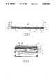
- FIG. 1is a perspective view of an elongate strip according to the present invention, showing a sealing member stamped from the strip and a corresponding cap;
- FIG. 2is a side view showing a section through the neck of a container including a sealing member according to the present invention, and a cap shown removed;
- FIG. 3is a sectional view of the neck of the container of FIG. 2, showing removal of the sealing member
- FIG. 4is a sectional view perpendicular to the axis of the elongate strip of FIG. 1;
- FIG. 5is a sectional view through a cap fitted with a sealing member of the present invention.
- an elongate strip according to the present inventionis designated by the numeral 1.
- the elongate strip 1can be of indefinite length, and can form part of a wider strip.
- the elongate strip 1has a membrane 2.
- a lower surface of the membrane 2is coated with a hot melt bonding material or adhesive 4.
- a sheet 6is a laminate sheet comprising a number of separate layers.
- the sheet 6has a first sheet 8. Between the first sheet 8 and membrane 2, there is a first layer of adhesive 10. This layer of adhesive 10 does not extend across the full width of the strip 1, as detailed below.
- a further layer of adhesive 12is provided on top of the first sheet 8 and bonds a second sheet 14 to the first sheet 8.
- the section through the elongate strip 1, shown in FIG. 4,is constant along its length (for clarity, the thickness of the various layers is amplified in FIG. 4).
- the first layer of adhesive 10comprises two portions. A major portion, designated 10a extends along the left hand side of the strip as viewed in FIG. 4. A narrow portion 10b can extend along the right hand side of the strip 1, again as viewed in FIG. 4. This leaves a gap 16, where the membrane 2 and first sheet 8 are not bonded to one another.
- the elongate strip 1would be produced as part of a wider strip containing a number of the elongate strips 1.
- the edges of the elongate strip 1are defined by the boundaries 18 in FIG. 4, and in the wider strip the elongate strips 1 would be continuous at their boundaries 18.
- the wide portion 10awould be continuous with the narrow portion 10b of an adjacent strip.
- Appropriate edge regionswould be provided along either edge of the wider strip.
- wider portions 10a, 10bwould be provided along either edge of the wider strip.
- each sealing memberis die cut generally centrally from the elongate strip 1 as indicated by the vertical lines 22 in FIG. 4.
- the sealing member 20is circular.
- the adhesive portion 10ahas a straight edge or line 11 which in the illustrated embodiment is straight bounding the gap 16. This line 11 extends approximately diametrically across the sealing member 20, as shown in FIG. 1.
- the sealing member 20thus includes a composite portion 23, and a separated portion 24 with the line 11 running between them.
- the wide portion 10a of the first layer of adhesiveresults in the various layers being bonded together.
- the laminate sheet 6is separate and free from the membrane 2.
- the sealing member 20is cut so as to be clear of the narrow portion 10b of the adhesive layer.
- the narrow portion 10bis included simply to hold the right hand edges of the membrane 2 and the laminate sheet 6 together to prevent them from flapping or becoming folded etc.
- the various dimensionscan be chosen so as to maximize the use of the material.
- the narrow portion 10bcan be kept as narrow as possible, and the width of the strip 1 and the spacing of the sealing members along it can be selected to obtain the maximum number of sealing members 20.
- a cap for screwing onto a containeris shown schematically at 30.
- the cap 30is a screw cap, and here is shown as being formed with a uniform wall thickness throughout its planar top wall and cylindrical side wall having a screw thread 34.
- the sealing member 20is pressed into the cap 30, and is shown in FIG. 5 with the composite and separated portions 23, 24 on the left hand and right hand sides of the figure respectively.
- the membrane 2is formed from alumium foil, the first sheet 8 from polyester and the second sheet 14 from paper.
- the edges of the member 20will ride over the ridges of the screw thread 34 of the cap 30.
- the resiliency of the sheet 8is sufficient to overcome the properties of the membrane 2.
- the second sheet 14does not greatly influence the resiliency of the sealing member 20. Consequently, as the edges of the sealing member 20 ride over the ridges 34, the periphery of the first sheet 8 deflects, but tends to spring back to maintain its planar configuration.
- the composite portion 23springs back to engage the grooves of the screw thread 34.
- the laminate sheet 6springs back to engage the grooves of the screw thread.
- the membrane 2, of the separated portion 24is not bonded to the sheet 8. Consequently, as it rides over the ridges 34 its edge deflects plastically, so as to be permanently deformed. This is indicated at 36. As a consequence, the membrane 2 in the separated portion 24 does not engage the screw threads. However, the engagement by the rest of the sealing member 20 holds the sealing member 20 in position.
- the cap 30is then screwed on to the neck of a bottle, indicated at 40 in FIG. 2 after filling of the bottle or other container.
- the cap 30is screwed on sufficiently, to press the sealing member 20 uniformly against the top of the neck 40.
- the deformed edge 36is then pressed against the laminate sheet 6 and conforms to the neck of the container.
- the disk 32enables a uniform pressure to be applied over the sealing member 20, so that a uniform pressure should be applied at all points between the sealing member 20 and neck 40.
- the bottle neck 40 with the cap 30is then passed through an induction heating apparatus.
- Thisuses high frequency fields to induce currents within the foil of the membrane 2. This heats the foil 2. The heat in turn causes the hot melt bonding material 4 to melt, and upon cooling it bonds the membrane to the top of the bottle neck 40.
- the bottleis then ready for distribution, sale, etc.
- the userIn use, to open the bottle, the user removes the screw cap 30 in the usual way. This then reveals the sealing member 20 bonded to the bottle 40. On one side, the laminated sheet 6 of the separated portion 24 forms a free tab 42. On the other side, the composite portion 23 is bonded to the bottle neck 40.
- the sealing member 20can then be removed by grasping the tab 42.
- the tab 42is grasped between two fingers and pulled in the direction of the arrows 44, i.e. the tab 42 is generally pulled laterally, rather than upwards.
- the composite portion 23is them pulled from the bottle neck 40, commencing on the portion remote from the separated portion 24. Further pulling at the tab 42 causes complete detachment of the composite portion 23, followed by detachment of the separated portion 24, as the bond strength of the first layer of adhesive 10 is sufficiently great relative to the bond strength of the hot melt bonding material or adhesive 4 that the membrane 2 and first sheet 8 are removable as a unit, as shown.
- the tab 42is pulled laterally, to make full use of the bond provided by the first layer of adhesive 10. If the tab 42 is pulled upwards, or away from the separated portion 24, there may be a tendency for the first layer of adhesive 10 to separate, depending upon the nature of the various materials used and bond strengths of the adhesive layer 4, 10. Pulling laterally causes the sealing member 20 to separate from lip or the bottle neck 40, as a single unit, to leave the neck 40 fully open.
- the preferred materials for the sealing member 20are as follows.
- the hot melt bonding materialis adhesive no. H0466 supplied by Industrial Adhesives.
- the first adhesive layer 10is a composite adhesive, namely Spenbond adhesive 650/651, supplied by NL Chemicals; adhesive 650 is a water dispersed urethane-laminating adhesive, whilst 651 is a water dispersable curing agent for the adhesive.
- the first sheet 8is a polyester, supplied by Dupont, having a thickness of 0.001 inches.
- the further adhesive layeris adhesive no. R0202, again supplied by Industrial Adhesives, this being a water born adhesive.
- the second sheet 14is a bleached kraft paper having a thickness of 0.004 inches and a nominal weight of 52 pounds.
- the top of the second sheet 14, which is formed from paper,is visible once the cap 30 has been removed from a bottle. Accordingly, it can be printed with suitable information. Thus, it can be printed with instructions, including arrows etc. indicating the direction in which the tab 42 is to be pulled. It can be printed with any other information desired, for example trade marks, logos, etc. identifying the product.
- a preferred manufacturing sequence for producing the stripsis as follows. For sealing members having a diameter of approximately 13/8 inches, a wide strip is produced having a width of 213/8 inches, including ten elongate strips 1. The wide strip is laminated together in the following sequence.
- the first and second sheets 8, 14are laminated together. This is achieved by applying adhesive in known manner to one of the sheets and then pressing these two sheets together. This forms the laminated sheet 6.
- the next stepis to dry bond the laminated sheet 6 to the metal foil or membrane 2. This is achieved by applying Spenbond 650/651 adhesive to the laminated sheet 6 (or alternatively to the foil 2), and allowing it to dry until tacky.
- the membrane or metal foil 2is then applied. Heat and pressure are then applied to the composite strip, to re-activate the glue and cause the membrane to become bonded to the laminate sheet 6.
- the Spenbond adhesiveforming the first adhesive layer 10 to be only applied in strips.
- the rolleressentially comprises raised parts, of constant radius, and slightly recessed parts. Only the recessed parts contact and transfer glue. A doctor blade wipes the adhesive of the raised parts so that they do not transfer any adhesive. Thus, a sheet passed across the roller receives strips of glue.
- the rolleris so dimensioned as to apply the glue in the desired pattern.
- the exposed surface of the membrane or foil 2is then coated with a hot melt bonding material in the known manner.
- the composite, wide stripis then formed. It is slit into the elongate strips 1 and printed.
- the wide strip having a width of 213/8 inchesis slit into three intermediate strips each including three elongate strips 1, and a separate single elongate strip 1. These three elongate strips and the single elongate strip 1 are then printed, prior to slitting each of the intermediate strips into three elongate strips 1.
- the various stepsare carried out on continuous lengths of the membrane 2 and first and second sheets 8, 14.
- the strip formedwas rewound, prior to carrying out the next step.
- suitable equipmentit may well be possible to carry out the various steps as a continuous operation.
- the sealing members 20are cut from them by die-cutting so that the various layers have a common periphery.
- the diesare perfectly shaped, to cleanly ut the sealing members 20.
- the dieis tapered and is deeper on the side for the separated portion 24.
- the sealing membersneed not necessarily be circular, but can be a variety of shapes, eg. a rounded rectangle, depending upon the nature of the container and the shape of its opening.
- the provision of the second sheet 14 and the corresponding layer of adhesiveare not always necessary.
- the single sheet 8 of polyester or the likemay be suitable.
- the width of the composite portion 23can be varied, depending upon the nature of the materials used, the shape of the opening, etc. In any event, the configuration should preferably be such as to ensure that the membrane 2 is always removed completely, rather than being torn and leaving parts of it in place. It is also possible that other combinations of materials could be used, depending upon the application.
- the tab free edgeneed not correspond exactly to the edge of the membrane. Instead, the tab can be made smaller and have various sizes.
- the cap usedneed not be a screw or even a circular cap. It could have plain side walls and a variety of shapes.
- the sealing membercan be sealed to a container by a variety of different techniques, e.g. a hot plate rather than induction heating. Further, an adhesive that does not require heating could be used.
Landscapes
- Engineering & Computer Science (AREA)
- Mechanical Engineering (AREA)
- Closures For Containers (AREA)
Abstract
Description
Claims (23)
Priority Applications (1)
| Application Number | Priority Date | Filing Date | Title |
|---|---|---|---|
| US07/530,529US5261990A (en) | 1987-09-09 | 1990-05-30 | Method of making an elongate strip for the production of sealing members for containers |
Applications Claiming Priority (4)
| Application Number | Priority Date | Filing Date | Title |
|---|---|---|---|
| CA546450 | 1987-09-09 | ||
| CA000546450ACA1336708C (en) | 1987-09-09 | 1987-09-09 | Sealing member for a container |
| US07162787US4961986B1 (en) | 1987-09-09 | 1988-03-02 | Sealing member for a container |
| US07/530,529US5261990A (en) | 1987-09-09 | 1990-05-30 | Method of making an elongate strip for the production of sealing members for containers |
Related Parent Applications (1)
| Application Number | Title | Priority Date | Filing Date |
|---|---|---|---|
| US07162787DivisionUS4961986B1 (en) | 1987-09-09 | 1988-03-02 | Sealing member for a container |
Publications (1)
| Publication Number | Publication Date |
|---|---|
| US5261990Atrue US5261990A (en) | 1993-11-16 |
Family
ID=27167769
Family Applications (1)
| Application Number | Title | Priority Date | Filing Date |
|---|---|---|---|
| US07/530,529Expired - LifetimeUS5261990A (en) | 1987-09-09 | 1990-05-30 | Method of making an elongate strip for the production of sealing members for containers |
Country Status (1)
| Country | Link |
|---|---|
| US (1) | US5261990A (en) |
Cited By (19)
| Publication number | Priority date | Publication date | Assignee | Title |
|---|---|---|---|---|
| US20040043165A1 (en)* | 2002-08-27 | 2004-03-04 | Van Hulle Keith Eugene | Lidding components for containers |
| US20060151415A1 (en)* | 2005-01-06 | 2006-07-13 | Joseph Smelko | Pull-tab sealing member with improved heat distribution for a container |
| WO2008027036A1 (en)* | 2006-08-29 | 2008-03-06 | Tech-Seal Products, Inc. | Tabbed container seal and method of manufacture |
| US20080283484A1 (en)* | 2005-03-08 | 2008-11-20 | Andreas Michalsky | Packaging Container, Especially Can-Like Container |
| US20090166240A1 (en)* | 2007-12-26 | 2009-07-02 | Scarola Leonard S | Container with grippable body and lid |
| CN101797554A (en)* | 2010-02-11 | 2010-08-11 | 姚玉琴 | Cut-coated bottle cap production process |
| US20120228297A1 (en)* | 2007-08-24 | 2012-09-13 | Selig Sealing Products, Inc. | Multi-Purpose Covering And Method Of Hygienically Covering A Container Top |
| US8468782B2 (en) | 2004-11-04 | 2013-06-25 | Herrmann Ultraschalltechnik Gmbh & Co. Kg | Method for producing a bottle-like or tubular container, particularly a tubular bag, comprising a sealed-in bottom, and a correspondingly produced tubular bag |
| US8715825B2 (en) | 2005-01-06 | 2014-05-06 | Selig Sealing Products, Inc. | Two-piece pull-tab sealing member with improved heat distribution for a container |
| US20180079576A1 (en)* | 2015-03-03 | 2018-03-22 | Selig Sealing Products, Inc. | Tabbed Seal Concepts |
| US10604315B2 (en) | 2014-02-05 | 2020-03-31 | Selig Sealing Products, Inc. | Dual aluminum tamper indicating tabbed sealing member |
| US10899506B2 (en) | 2016-10-28 | 2021-01-26 | Selig Sealing Products, Inc. | Single aluminum tamper indicating tabbed sealing member |
| US10934069B2 (en) | 2016-10-28 | 2021-03-02 | Selig Sealing Products, Inc. | Sealing member for use with fat containing compositions |
| US10954032B2 (en) | 2012-09-05 | 2021-03-23 | Selig Sealing Products, Inc. | Tamper evident tabbed sealing member having a foamed polymer layer |
| US11254481B2 (en) | 2018-09-11 | 2022-02-22 | Selig Sealing Products, Inc. | Enhancements for tabbed seal |
| US11708198B2 (en) | 2018-07-09 | 2023-07-25 | Selig Sealing Products, Inc. | Grip enhancements for tabbed seal |
| US11866242B2 (en) | 2016-10-31 | 2024-01-09 | Selig Sealing Products, Inc. | Tabbed inner seal |
| US12269659B2 (en) | 2019-11-29 | 2025-04-08 | Selig Sealing Products, Inc. | Foil free tabbed seal |
| US12377630B2 (en) | 2020-05-29 | 2025-08-05 | Selig Sealing Products, Inc. | Dispensing liner |
Citations (18)
| Publication number | Priority date | Publication date | Assignee | Title |
|---|---|---|---|---|
| US713824A (en)* | 1901-09-28 | 1902-11-18 | George White Jr | Bottle-closure. |
| US902843A (en)* | 1908-05-28 | 1908-11-03 | Henry S Sheppard | Method of making bottle-closures. |
| US1073071A (en)* | 1912-08-21 | 1913-09-09 | Hall Milk Bottle Cap Company | Milk-bottle seal. |
| US2050248A (en)* | 1934-08-24 | 1936-08-11 | Gutmann & Co Ferd | Strip material for container closures |
| US3411419A (en)* | 1966-02-16 | 1968-11-19 | Reynolds Metals Co | Method of making a container having multilayer wall means |
| US3549440A (en)* | 1967-10-26 | 1970-12-22 | United Glass Ltd | Method for sealing a membrane to the mouth of a container utilizing induced radio frequency current |
| US3923198A (en)* | 1973-09-17 | 1975-12-02 | Minnesota Mining & Mfg | Stress-opacifiable tamper indicator |
| FR2327161A1 (en)* | 1975-10-08 | 1977-05-06 | Tuboplast France | Aluminium seal for products sold in tube - has tear off tab heat welded into position after closing tube |
| US4256528A (en)* | 1979-05-23 | 1981-03-17 | Minnesota Mining And Manufacturing Company | Machine for forming openings sealed by manually removable lengths of tape in can ends |
| US4452842A (en)* | 1982-05-19 | 1984-06-05 | Borges Gary G | Laminated lidding material |
| EP0135431A1 (en)* | 1983-08-24 | 1985-03-27 | Societe Alsacienne D'aluminium | Manufacturing process for container lids to be opened by peeling, and lids obtained by the realisation of this method |
| US4514248A (en)* | 1982-06-07 | 1985-04-30 | U.S. Clinical Products, Inc. | Method of making a flexible sterile closure system for containers |
| US4565738A (en)* | 1983-06-01 | 1986-01-21 | Imperial Chemical Industries, Plc | Multiple-layer polyolefin films |
| US4579240A (en)* | 1984-11-09 | 1986-04-01 | Minnesota Mining And Manufacturing Company | Tamper indicating cap assembly |
| US4588465A (en)* | 1983-02-04 | 1986-05-13 | Minnesota Mining And Manufacturing Company | Method for forming a sealed container |
| US4673601A (en)* | 1984-05-07 | 1987-06-16 | Nyffeler, Corti Ag | Cold- or heat-sealable composite film for reclosable packages |
| US4754890A (en)* | 1987-08-20 | 1988-07-05 | Ullman Myron E | Tamper evident safety seal |
| US4762246A (en)* | 1984-12-13 | 1988-08-09 | Metal Box Public Limited Company | Containers |
- 1990
- 1990-05-30USUS07/530,529patent/US5261990A/ennot_activeExpired - Lifetime
Patent Citations (18)
| Publication number | Priority date | Publication date | Assignee | Title |
|---|---|---|---|---|
| US713824A (en)* | 1901-09-28 | 1902-11-18 | George White Jr | Bottle-closure. |
| US902843A (en)* | 1908-05-28 | 1908-11-03 | Henry S Sheppard | Method of making bottle-closures. |
| US1073071A (en)* | 1912-08-21 | 1913-09-09 | Hall Milk Bottle Cap Company | Milk-bottle seal. |
| US2050248A (en)* | 1934-08-24 | 1936-08-11 | Gutmann & Co Ferd | Strip material for container closures |
| US3411419A (en)* | 1966-02-16 | 1968-11-19 | Reynolds Metals Co | Method of making a container having multilayer wall means |
| US3549440A (en)* | 1967-10-26 | 1970-12-22 | United Glass Ltd | Method for sealing a membrane to the mouth of a container utilizing induced radio frequency current |
| US3923198A (en)* | 1973-09-17 | 1975-12-02 | Minnesota Mining & Mfg | Stress-opacifiable tamper indicator |
| FR2327161A1 (en)* | 1975-10-08 | 1977-05-06 | Tuboplast France | Aluminium seal for products sold in tube - has tear off tab heat welded into position after closing tube |
| US4256528A (en)* | 1979-05-23 | 1981-03-17 | Minnesota Mining And Manufacturing Company | Machine for forming openings sealed by manually removable lengths of tape in can ends |
| US4452842A (en)* | 1982-05-19 | 1984-06-05 | Borges Gary G | Laminated lidding material |
| US4514248A (en)* | 1982-06-07 | 1985-04-30 | U.S. Clinical Products, Inc. | Method of making a flexible sterile closure system for containers |
| US4588465A (en)* | 1983-02-04 | 1986-05-13 | Minnesota Mining And Manufacturing Company | Method for forming a sealed container |
| US4565738A (en)* | 1983-06-01 | 1986-01-21 | Imperial Chemical Industries, Plc | Multiple-layer polyolefin films |
| EP0135431A1 (en)* | 1983-08-24 | 1985-03-27 | Societe Alsacienne D'aluminium | Manufacturing process for container lids to be opened by peeling, and lids obtained by the realisation of this method |
| US4673601A (en)* | 1984-05-07 | 1987-06-16 | Nyffeler, Corti Ag | Cold- or heat-sealable composite film for reclosable packages |
| US4579240A (en)* | 1984-11-09 | 1986-04-01 | Minnesota Mining And Manufacturing Company | Tamper indicating cap assembly |
| US4762246A (en)* | 1984-12-13 | 1988-08-09 | Metal Box Public Limited Company | Containers |
| US4754890A (en)* | 1987-08-20 | 1988-07-05 | Ullman Myron E | Tamper evident safety seal |
Cited By (27)
| Publication number | Priority date | Publication date | Assignee | Title |
|---|---|---|---|---|
| WO2004020307A3 (en)* | 2002-08-27 | 2004-11-04 | Rjr Packaging Llc | Lidding components for containers |
| US20040043165A1 (en)* | 2002-08-27 | 2004-03-04 | Van Hulle Keith Eugene | Lidding components for containers |
| US8468782B2 (en) | 2004-11-04 | 2013-06-25 | Herrmann Ultraschalltechnik Gmbh & Co. Kg | Method for producing a bottle-like or tubular container, particularly a tubular bag, comprising a sealed-in bottom, and a correspondingly produced tubular bag |
| US8715825B2 (en) | 2005-01-06 | 2014-05-06 | Selig Sealing Products, Inc. | Two-piece pull-tab sealing member with improved heat distribution for a container |
| US20060151415A1 (en)* | 2005-01-06 | 2006-07-13 | Joseph Smelko | Pull-tab sealing member with improved heat distribution for a container |
| US8057896B2 (en) | 2005-01-06 | 2011-11-15 | Selig Sealing Products, Inc. | Pull-tab sealing member with improved heat distribution for a container |
| US20080283484A1 (en)* | 2005-03-08 | 2008-11-20 | Andreas Michalsky | Packaging Container, Especially Can-Like Container |
| WO2008027036A1 (en)* | 2006-08-29 | 2008-03-06 | Tech-Seal Products, Inc. | Tabbed container seal and method of manufacture |
| US9278506B2 (en)* | 2007-08-24 | 2016-03-08 | Selig Sealing Products, Inc. | Non-metallic, tabbed multi-purpose covering for hygienically covering a container top |
| US20120228297A1 (en)* | 2007-08-24 | 2012-09-13 | Selig Sealing Products, Inc. | Multi-Purpose Covering And Method Of Hygienically Covering A Container Top |
| US20090166240A1 (en)* | 2007-12-26 | 2009-07-02 | Scarola Leonard S | Container with grippable body and lid |
| CN101797554A (en)* | 2010-02-11 | 2010-08-11 | 姚玉琴 | Cut-coated bottle cap production process |
| CN101797554B (en)* | 2010-02-11 | 2012-04-25 | 上海紫泉包装有限公司 | Cut-coated bottle cap production process |
| US10954032B2 (en) | 2012-09-05 | 2021-03-23 | Selig Sealing Products, Inc. | Tamper evident tabbed sealing member having a foamed polymer layer |
| US10604315B2 (en) | 2014-02-05 | 2020-03-31 | Selig Sealing Products, Inc. | Dual aluminum tamper indicating tabbed sealing member |
| US10556732B2 (en)* | 2015-03-03 | 2020-02-11 | Selig Sealing Products, Inc. | Tabbed seal concepts |
| US20180079576A1 (en)* | 2015-03-03 | 2018-03-22 | Selig Sealing Products, Inc. | Tabbed Seal Concepts |
| US11059644B2 (en) | 2015-03-03 | 2021-07-13 | Selig Sealing Products, Inc. | Tabbed seal concepts |
| US10899506B2 (en) | 2016-10-28 | 2021-01-26 | Selig Sealing Products, Inc. | Single aluminum tamper indicating tabbed sealing member |
| US10934069B2 (en) | 2016-10-28 | 2021-03-02 | Selig Sealing Products, Inc. | Sealing member for use with fat containing compositions |
| US11401080B2 (en) | 2016-10-28 | 2022-08-02 | Selig Sealing Products, Inc. | Single aluminum tamper indicating tabbed sealing member |
| US11866242B2 (en) | 2016-10-31 | 2024-01-09 | Selig Sealing Products, Inc. | Tabbed inner seal |
| US11708198B2 (en) | 2018-07-09 | 2023-07-25 | Selig Sealing Products, Inc. | Grip enhancements for tabbed seal |
| US11724863B2 (en) | 2018-07-09 | 2023-08-15 | Selig Sealing Products, Inc. | Tabbed seal with oversized tab |
| US11254481B2 (en) | 2018-09-11 | 2022-02-22 | Selig Sealing Products, Inc. | Enhancements for tabbed seal |
| US12269659B2 (en) | 2019-11-29 | 2025-04-08 | Selig Sealing Products, Inc. | Foil free tabbed seal |
| US12377630B2 (en) | 2020-05-29 | 2025-08-05 | Selig Sealing Products, Inc. | Dispensing liner |
Similar Documents
| Publication | Publication Date | Title |
|---|---|---|
| US4961986A (en) | Sealing member for a container | |
| US5514442A (en) | Sealing member for a container | |
| US5261990A (en) | Method of making an elongate strip for the production of sealing members for containers | |
| US5217790A (en) | Elongate strip for the production of sealing members for containers | |
| US6767604B2 (en) | Package with attached resealable cover and method of making same | |
| US5702015A (en) | Closure seal for container | |
| US4960216A (en) | Partially laminated closure cap for tamper proof container and method of making same | |
| US4588099A (en) | Film seal for container | |
| US6033762A (en) | Self-adhesive resealable tamper-evident tape | |
| US4822326A (en) | Method of forming a tamper evident sealing liner | |
| US4394917A (en) | Sealed closure-container package | |
| US7832580B2 (en) | Tamper evident container seal with integral pull opener | |
| EP2830966B1 (en) | Resealable package, method for producing the resealable package and apparatus for producing the resealable package | |
| WO2025106185A1 (en) | Induction heat sealable closure liner configured for paper or plastic recycling stream, and induction heat seal application device | |
| US8580067B2 (en) | Thermo-sealing control method and packaging for resealable packaging | |
| USRE33886E (en) | Method of forming a tamper evident sealing liner | |
| US20050042414A1 (en) | Methods of making sealing members for induction sealing of containers | |
| GB2366790A (en) | Tamper evident closure | |
| DE69106719T2 (en) | CONTAINER LOCK. | |
| US20150089905A1 (en) | Thermo-sealing control method and packaging for resealable packaging | |
| CN111032523B (en) | Seal, method of dry lamination and method of die cutting | |
| JPS58216523A (en) | Method for sealing synthetic resin containers to prevent tampering |
Legal Events
| Date | Code | Title | Description |
|---|---|---|---|
| AS | Assignment | Owner name:STANPAC INC. Free format text:ASSIGNMENT OF ASSIGNORS INTEREST.;ASSIGNOR:WITT, STEPHEN H.;REEL/FRAME:005733/0610 Effective date:19910123 Owner name:ORTECH INTERNATIONAL Free format text:ASSIGNMENT OF ASSIGNORS INTEREST.;ASSIGNOR:GALDA, MICHAEL P.;REEL/FRAME:005733/0615 Effective date:19910306 Owner name:ORTECH INTERNATIONAL Free format text:ASSIGNMENT OF ASSIGNORS INTEREST.;ASSIGNOR:KLASSEN, BRIAN M.;REEL/FRAME:005733/0620 Effective date:19910129 Owner name:STANPAC INC. A CORPORATION OF ONTARIO Free format text:ASSIGNMENT OF ASSIGNORS INTEREST.;ASSIGNOR:ORTECH INTERNATIONAL;REEL/FRAME:005733/0625 Effective date:19910402 | |
| STCF | Information on status: patent grant | Free format text:PATENTED CASE | |
| CC | Certificate of correction | ||
| FPAY | Fee payment | Year of fee payment:4 | |
| FEPP | Fee payment procedure | Free format text:PAYOR NUMBER ASSIGNED (ORIGINAL EVENT CODE: ASPN); ENTITY STATUS OF PATENT OWNER: LARGE ENTITY | |
| FPAY | Fee payment | Year of fee payment:8 | |
| AS | Assignment | Owner name:ILLINOIS TOOL WORKS INC., ILLINOIS Free format text:ASSIGNMENT OF ASSIGNORS INTEREST;ASSIGNOR:STANPAC INC.;REEL/FRAME:012581/0043 Effective date:20011221 | |
| FPAY | Fee payment | Year of fee payment:12 | |
| AS | Assignment | Owner name:WYNN'S CANADA LTD., CANADA Free format text:ASSIGNMENT OF ASSIGNORS INTEREST;ASSIGNOR:UNIPAC CORPORATION;REEL/FRAME:021281/0080 Effective date:20080530 Owner name:ITW CANADA, CANADA Free format text:ASSIGNMENT OF ASSIGNORS INTEREST;ASSIGNOR:WYNN'S CANADA LTD.;REEL/FRAME:021281/0087 Effective date:20080530 Owner name:UNIPAC CORPORATION, CANADA Free format text:ASSIGNMENT OF ASSIGNORS INTEREST;ASSIGNOR:ILLINOIS TOOL WORKS INC.;REEL/FRAME:021281/0072 Effective date:20080530 | |
| AS | Assignment | Owner name:ILLINOIS TOOL WORKS INC., ILLINOIS Free format text:ASSIGNMENT OF ASSIGNORS INTEREST;ASSIGNOR:ITW CANADA;REEL/FRAME:021316/0116 Effective date:20080730 | |
| AS | Assignment | Owner name:SELIG SEALING PRODUCTS, INC., ILLINOIS Free format text:ASSIGNMENT OF ASSIGNORS INTEREST;ASSIGNOR:ILLINOIS TOOL WORKS INC.;REEL/FRAME:021328/0290 Effective date:20080801 | |
| AS | Assignment | Owner name:GENERAL ELECTRIC CAPITAL CORPORATION, AS US AGENT, Free format text:SECURITY AGREEMENT;ASSIGNOR:SELIG SEALING PRODUCTS, INC.;REEL/FRAME:021428/0634 Effective date:20080801 | |
| AS | Assignment | Owner name:CANADIAN IMPERIAL BANK OF COMMERCE, CANADA Free format text:SECURITY AGREEMENT;ASSIGNOR:STANPAC INC.;REEL/FRAME:026799/0914 Effective date:20100409 | |
| AS | Assignment | Owner name:PNC BANK CANADA BRANCH, CANADA Free format text:SECURITY AGREEMENT;ASSIGNOR:STANPAC INC.;REEL/FRAME:027592/0555 Effective date:20111228 Owner name:STANPAC INC., CANADA Free format text:RELEASE BY SECURED PARTY;ASSIGNOR:CANADIAN IMPERIAL BANK OF COMMERCE;REEL/FRAME:027591/0712 Effective date:20120119 | |
| AS | Assignment | Owner name:SELIG SEALING PRODUCTS, INC., ILLINOIS Free format text:RELEASE OF SECURITY INTEREST IN INTELLECTUAL PROPERTY COLLATERAL;ASSIGNOR:GENERAL ELECTRIC CAPITAL CORPORATION, AS US AGENT;REEL/FRAME:028550/0177 Effective date:20120711 |