US5261633A - Pipe support system - Google Patents
Pipe support systemDownload PDFInfo
- Publication number
- US5261633A US5261633AUS07/992,626US99262692AUS5261633AUS 5261633 AUS5261633 AUS 5261633AUS 99262692 AUS99262692 AUS 99262692AUS 5261633 AUS5261633 AUS 5261633A
- Authority
- US
- United States
- Prior art keywords
- hanger
- carrier unit
- pipe
- invention described
- annular
- Prior art date
- Legal status (The legal status is an assumption and is not a legal conclusion. Google has not performed a legal analysis and makes no representation as to the accuracy of the status listed.)
- Expired - Lifetime
Links
- 230000005540biological transmissionEffects0.000abstractdescription3
- 238000000034methodMethods0.000description7
- 239000000969carrierSubstances0.000description4
- 238000010276constructionMethods0.000description4
- VNWKTOKETHGBQD-UHFFFAOYSA-NmethaneChemical compoundCVNWKTOKETHGBQD-UHFFFAOYSA-N0.000description4
- 239000000463materialSubstances0.000description3
- 239000002184metalSubstances0.000description3
- 238000009428plumbingMethods0.000description3
- 238000009435building constructionMethods0.000description2
- 238000003780insertionMethods0.000description2
- 230000037431insertionEffects0.000description2
- 238000009434installationMethods0.000description2
- 239000003345natural gasSubstances0.000description2
- 229920003023plasticPolymers0.000description2
- XLYOFNOQVPJJNP-UHFFFAOYSA-NwaterSubstancesOXLYOFNOQVPJJNP-UHFFFAOYSA-N0.000description2
- 230000004075alterationEffects0.000description1
- 230000009172burstingEffects0.000description1
- 238000005868electrolysis reactionMethods0.000description1
- 229920002457flexible plasticPolymers0.000description1
- 229920005570flexible polymerPolymers0.000description1
- 238000012986modificationMethods0.000description1
- 230000004048modificationEffects0.000description1
- 238000000926separation methodMethods0.000description1
Images


Classifications
- F—MECHANICAL ENGINEERING; LIGHTING; HEATING; WEAPONS; BLASTING
- F16—ENGINEERING ELEMENTS AND UNITS; GENERAL MEASURES FOR PRODUCING AND MAINTAINING EFFECTIVE FUNCTIONING OF MACHINES OR INSTALLATIONS; THERMAL INSULATION IN GENERAL
- F16L—PIPES; JOINTS OR FITTINGS FOR PIPES; SUPPORTS FOR PIPES, CABLES OR PROTECTIVE TUBING; MEANS FOR THERMAL INSULATION IN GENERAL
- F16L3/00—Supports for pipes, cables or protective tubing, e.g. hangers, holders, clamps, cleats, clips, brackets
- F16L3/16—Supports for pipes, cables or protective tubing, e.g. hangers, holders, clamps, cleats, clips, brackets with special provision allowing movement of the pipe
- F16L3/18—Supports for pipes, cables or protective tubing, e.g. hangers, holders, clamps, cleats, clips, brackets with special provision allowing movement of the pipe allowing movement in axial direction
Definitions
- the present inventionrelates to pipe support systems used in building construction, and more particularly to a new and improved carrier unit and system that allows for the simple, convenient and organized support of one or more conduit pipes designed to survive the shifting and stress of a minor earthquake.
- conduit pipingIn the field of building construction, conduit piping is widely used for such purposes as plumbing, carrying electrical cable, and/or serving mechanical purposes (air intake/exhaust, natural gas, etc.). Such conduit piping is generally installed behind walls, below floors, above ceilings, or in crawl spaces between floors of multiple-story buildings. In the construction of both commercial and residential structures, there is often a need to run great lengths of conduit piping in a straight line or in a uniform way. Present methods of mounting conduit pipe to a building utilize one or more separate and independent clamps or straps for support.
- U.S. Pat. No. 3,684,223 to Logsdondescribes a pipe clamp having a slotted cylindrical center section having ridges extending towards its interior for holding a pipe in place but away from the mounting surface. Although this clamp accomplishes some separation, there is no float or play between the pipe and the clamp itself. Thus, in the event of an earthquake, this clamp may well cause the pipe to rupture.
- a second problem presented by existing methodsis providing a way to uniformly (i.e. in a straight line) mount a long run of pipe, especially when the pipe has pre-determined curves or joints in it which must be set before the pipe is mounted to the building.
- a preconstructed pipe mounted below a floorwill dangle and likely break as it is slowly attached to the floor joists one clamp at a time; then, because of the joist by joist mounting method, the pipe may wind up out of place, crooked, or unduly stressed.
- a third problem inherent in existing methodsis the unnecessary duplication of support clamps for the various different pipes that may be installed in generally the same places.
- the plumbing, electrical and mechanical tradestend to make their conduit pipe installations at different times during the course of a given construction project.
- a different skilled workerwill independently follow the same pattern of measuring, holding, clamping, and connecting his particular pipe in roughly the same place as the previous skilled worker who mounted his own separate pipe. This results in considerable wasted time.
- the present inventionovercomes the problems presented by existing pipe mounting methods by providing a cushioned circular pipe carrier that is wrapped tightly around a conduit pipe, and then held in place by a two-piece support hanger or block.
- the circular carrieritself may be either an "O" shaped ring having a single slit therein that may be opened to allow insertion of a pipe; or it may be in the form of two "C" shaped members that are placed around the pipe to encircle it.
- a mountable two-piece support hanger or block having a circular opening thereinis provided to hold the carrier (and hence, the pipe) in place.
- the cushion of the circular carrierseparates the pipe from the hanger or block, and through a special design provides the necessary float or play to help the pipe survive settling or shifting movement such as that of a minor earthquake.
- the hanger embodimentmay hinged, and may include one of several varieties adapted for mounting it on (FIG. 4), above, below (FIG. 1), or through (FIG. 11) a support member.
- the block embodimentis designed for use in conjunction with a rail, where the rail itself is mounted to a support member.
- the blockis provided with tabs which fit into corresponding openings on the rail in order to hold the block firmly in place.
- Multiple railsmay be pre-aligned and mounted where the pipe is to be placed. Then a series of blocks may be mounted in the same places on each rail to receive the circular carriers holding the pipe.
- Several series of blocksmay be mounted on the same set of rails, thereby providing an organized system for mounting multiple pipes for different uses.
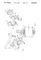
- FIG. 1is a perspective view of the high-ear hinged embodiment of the present invention partially mounted below a cross beam.
- FIG. 2is a partially exploded view of the high-ear hinged embodiment of the present invention.
- FIG. 3is a cross-sectional cutaway view along line 3--3 of FIG. 1 showing the high-ear hinged embodiment of the invention in place around a conduit pipe below a cross beam.
- FIG. 4is a perspective view of the flat-ear hinged embodiment of the present invention mounted on the side of a beam.
- FIG. 5is a cross-sectional cutaway view along line 5--5 of FIG. 4 showing the flat-ear hinged embodiment of the invention in place around a conduit pipe mounted on the side of a beam.
- FIG. 6is a partially exploded view of the flat-ear hinged embodiment of the present invention, showing the two alternative embodiments of the carrier and insert units.
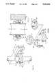
- FIG. 7is a perspective view of the single-pipe block embodiment of the present invention attached to a rail mounted on a beam.
- FIG. 8is a partially exploded view of the single-pipe block and divided carrier embodiments of the present invention.
- FIG. 9is a perspective view of a series of both the single-pipe and the multiple-pipe block embodiments of the present invention attached to a series of rails mounted on parallel beams.
- FIG. 10is a partially exploded view of the multiple-pipe block and unitary carrier embodiments of the present invention.
- FIG. 11is a perspective view of the high-ear hinged embodiment of the invention using the leading lip thereof to guide the invention into opening in a wall.
- FIG. 12is a cross-sectional cutaway view along line 12--12 of FIG. 11 showing the high-ear hinged embodiment of the invention in place in an opening in a wall.
- FIG. 13is a perspective view a single-pipe block embodiment of the present invention attached to a series of rails mounted in concrete or masonry.
- the inventionincludes an insert or carrier unit, generally designated as 25, made up of a cushion 26 having a C-shaped cross-sectional area which partially encompasses a rigid alignment strip 27 having a T-shaped cross-sectional area.
- This cross-sectional area of the carrier unit 25is detailed in FIGS. 3, 5, and 8.
- the carrier unit 25may be a single generally circular shaped piece having a single slit therein that may be opened to allow insertion of a pipe 20; or it may be in the form of two halves each generally having a "C" shape that are placed around the pipe to encircle it (see FIG. 6).
- the carrier unit 25may be have different forms (oval, hexagonal, square, triangular, etc.) depending upon its intended use.
- a hanger receptacle unit made up of two generally semicircular pieces 30a and 30bis provided to hold carrier unit 25.
- Each piece 30a and 30bincludes a generally semi-circular lip 33 bisected by a generally semi-circular groove 31.
- the protruding bottom portion of T-shaped alignment strip 27fits part way into groove 31 leaving an important air space gap 32 as shown in FIG. 3.
- the generally C-shaped cushion 26is thereby placed snugly in contact between the inside of lip 33 and the outside of pipe 20 (see FIGS. 3 and 5).
- Carrier unit 25may thereby be placed around pipe 20, and pieces 30a and 30b are closed together around carrier unit 25 to hold the pipe snugly in place.
- Gap 32provides a critical amount of float or play in the event of movement or shifting of a pipe so mounted.
- a pair of mounting flanges 37a and 37bare provided, one at each end of pieces 30a and 30b.
- These flangesmay be of a "low-ear” variety (shown as 37a and 37b in FIGS. 1, 2 and 3) which allow the hanger to be mounted above or below a support member 21; or they may be of a "high-ear” variety (shown as 38a and 38b in FIGS. 4, 5 and 6) which allow the hanger to be mounted along or on a support member 21.
- Each flangeincludes a hole 36 into which a screw or other mounting means 39 may be inserted to hold the hanger receptacle unit in place against a wooden beam or other support member 21.
- a hinge meansincluding a pivot 40 and a joint 41.
- the hingeallows the user to mount half of the hanger 30a before the carrier unit 25 is placed around the pipe 20.
- the pipe 20 with carrier unit 25 installedmay then be fitted and adjusted before the other half of hanger 30b is pivoted up and mounted around the carrier unit 25 (see FIG. 1).
- a single-pipe block 45 having two-pieces 45a and 45bis also provided as an alternative means for holding a single carrier unit 25, as shown in FIGS. 7 and 8.
- Each piece of block 45includes a groove 31 into which T-shaped alignment strip 27 fits part way leaving gap 32 for float or play.
- Lower block piece 45ais provided with a plurality of tabs 49 along one or both of its sides, or on the top or bottom, which tabs are designed to lock into corresponding slots 48 such as those on rail 50 as shown in FIG. 7.
- Rail 50may be mounted in a number of different ways including, without limitation, vertically along a support member 21 as shown in FIG. 7, embedded in masonry 24 as shown in FIG. 13, horizontally between posts (not shown), or hung vertically below a horizontal floor joist (not shown). Horizontal mounting of rail 50 would employ blocks 45 with tabs 49 along the top or bottom of the block.
- lower half block 45amay be locked onto rail 50, and one half of the generally C-shaped version of carrier unit 25 may be placed therein.
- Pipe 20may then be cradled in said half unit 25 as adjustments, connections and alterations are made.
- the other half of carrier unit 25is then placed over pipe 20 and the upper half of block 45b is locked onto lower half block 45a through locking means 46.
- mounting means 43such as a screw
- lower half block 45ais all that is necessary to support such things as air duct work, where vibrations and slippage are not critical.
- the carrier unitmay be of a different shape (e.g. square, oval, triangular, hexagonal, etc.).
- a multiple-pipe block 55 having two-pieces 55a and 55bis also provided as an alternative means for holding a plurality of carrier units 25, as shown in FIG. 10.
- a series of rails 50may be provided for mounting a series of blocks 45 or 55 in order to carry a plurality of pipes as shown in FIGS. 9 and 13. This provides for highly organized mounting of carrier units 25 and pipes 20, which is especially convenient for pipes added at a later time.
- lip 33 of the "high-ear” version of hanger 37may be extended so as to act as a guide for hanger 37 when fitted into an opening in a wall 52. This allows for placement of pipe carrier unit 25 on a pipe passing through a wall.
- Rail 50should be made of metal or other suitable rigid material, as should blocks 45 and 55.
- hangers 30may be made of rigid plastic or metal, depending upon the desired strength.
- the preferred embodimentallows for the installation of a series of rails 50 at an early stage in construction.
- the railsmay erected horizontally or vertically, and be embedded in masonry (FIG. 13), hung from floor joists, mounted on ceiling joists, attached along support members (FIG. 7), or the like. Once in place, any number of blocks 45 (or 55) may then be mounted onto the rails in order to hold the special carrier units 25 which hold the conduit pipe(s) in place.
- This systemprovides an extremely convenient and organized solution to the many problems associated with installing conduit pipe, and will significantly reduce construction costs by saving many a man hour.
Landscapes
- Engineering & Computer Science (AREA)
- General Engineering & Computer Science (AREA)
- Mechanical Engineering (AREA)
- Supports For Pipes And Cables (AREA)
Abstract
Description
The present invention relates to pipe support systems used in building construction, and more particularly to a new and improved carrier unit and system that allows for the simple, convenient and organized support of one or more conduit pipes designed to survive the shifting and stress of a minor earthquake.
In the field of building construction, conduit piping is widely used for such purposes as plumbing, carrying electrical cable, and/or serving mechanical purposes (air intake/exhaust, natural gas, etc.). Such conduit piping is generally installed behind walls, below floors, above ceilings, or in crawl spaces between floors of multiple-story buildings. In the construction of both commercial and residential structures, there is often a need to run great lengths of conduit piping in a straight line or in a uniform way. Present methods of mounting conduit pipe to a building utilize one or more separate and independent clamps or straps for support.
Numerous problems are presented by the existing methods of supporting conduit pipe. First, is the problem of isolating the pipe from the structure to which it is mounted. Most existing pipe clamps are in the shape of a modified "U" (or horseshoe) which is strapped over the pipe and attached directly to a support member. This brings the pipe into direct contact with the support member which allows the transmission of sound (e.g. water hammer) to the member and throughout the structure. Heat transmission and electrolysis may also take place. However, the most significant problem presented by not isolating the pipe from the structure occurs when there is movement of the structure as a result of such things as an earthquake or other shifting or settling. Countless fires have been caused by natural gas pipes which rupture as a result of an earthquake, which damage is compounded by the inability to deliver water because of these pipes bursting as well.
U.S. Pat. No. 3,684,223 to Logsdon describes a pipe clamp having a slotted cylindrical center section having ridges extending towards its interior for holding a pipe in place but away from the mounting surface. Although this clamp accomplishes some separation, there is no float or play between the pipe and the clamp itself. Thus, in the event of an earthquake, this clamp may well cause the pipe to rupture.
A second problem presented by existing methods is providing a way to uniformly (i.e. in a straight line) mount a long run of pipe, especially when the pipe has pre-determined curves or joints in it which must be set before the pipe is mounted to the building. Under existing methods, such a preconstructed pipe mounted below a floor will dangle and likely break as it is slowly attached to the floor joists one clamp at a time; then, because of the joist by joist mounting method, the pipe may wind up out of place, crooked, or unduly stressed.
A third problem inherent in existing methods is the unnecessary duplication of support clamps for the various different pipes that may be installed in generally the same places. In present building practice, the plumbing, electrical and mechanical trades tend to make their conduit pipe installations at different times during the course of a given construction project. For each such pipe (plumbing, electrical, mechanical, etc.) a different skilled worker will independently follow the same pattern of measuring, holding, clamping, and connecting his particular pipe in roughly the same place as the previous skilled worker who mounted his own separate pipe. This results in considerable wasted time.
The present invention overcomes the problems presented by existing pipe mounting methods by providing a cushioned circular pipe carrier that is wrapped tightly around a conduit pipe, and then held in place by a two-piece support hanger or block. The circular carrier itself may be either an "O" shaped ring having a single slit therein that may be opened to allow insertion of a pipe; or it may be in the form of two "C" shaped members that are placed around the pipe to encircle it.
A mountable two-piece support hanger or block having a circular opening therein is provided to hold the carrier (and hence, the pipe) in place. The cushion of the circular carrier separates the pipe from the hanger or block, and through a special design provides the necessary float or play to help the pipe survive settling or shifting movement such as that of a minor earthquake.
The hanger embodiment may hinged, and may include one of several varieties adapted for mounting it on (FIG. 4), above, below (FIG. 1), or through (FIG. 11) a support member. The block embodiment is designed for use in conjunction with a rail, where the rail itself is mounted to a support member. The block is provided with tabs which fit into corresponding openings on the rail in order to hold the block firmly in place. Multiple rails may be pre-aligned and mounted where the pipe is to be placed. Then a series of blocks may be mounted in the same places on each rail to receive the circular carriers holding the pipe. Several series of blocks may be mounted on the same set of rails, thereby providing an organized system for mounting multiple pipes for different uses.
It is therefore a primary object of the present invention to provide a cushioned carrier for holding a conduit pipe that isolates the pipe from the surface to which it is mounted and which provides sufficient float or play to help the pipe survive the stress of a minor earthquake or other shift without rupturing.
It is a further important object of the present invention to provide a (hinged) hanger for holding such a cushioned carrier of conduit pipe which hanger may be mounted above, below, on or through a mounting surface.
It is a further important object of the present invention to provide a rail-mountable block for holding such a cushioned carrier of conduit pipe above, below or on a mounting surface.
It is a further object of the present invention to provide a series of rail-mountable blocks for holding a series of cushioned carriers attached to a single conduit pipe in an organized and fashion above, below or on a mounting surface.
It is a further object of the present invention to provide a single rail-mountable block for holding a plurality of such cushioned carriers of conduit pipe above, below or on a mounting surface.
It is a further object of the present invention to provide a series of rail-mountable blocks, each block capable of holding a plurality of such cushioned carriers, attached to a plurality conduit pipes in an organized and uniform fashion above, below or on a mounting surface.
FIG. 1 is a perspective view of the high-ear hinged embodiment of the present invention partially mounted below a cross beam.
FIG. 2 is a partially exploded view of the high-ear hinged embodiment of the present invention.
FIG. 3 is a cross-sectional cutaway view along line 3--3 of FIG. 1 showing the high-ear hinged embodiment of the invention in place around a conduit pipe below a cross beam.
FIG. 4 is a perspective view of the flat-ear hinged embodiment of the present invention mounted on the side of a beam.
FIG. 5 is a cross-sectional cutaway view alongline 5--5 of FIG. 4 showing the flat-ear hinged embodiment of the invention in place around a conduit pipe mounted on the side of a beam.
FIG. 6 is a partially exploded view of the flat-ear hinged embodiment of the present invention, showing the two alternative embodiments of the carrier and insert units.
FIG. 7 is a perspective view of the single-pipe block embodiment of the present invention attached to a rail mounted on a beam.
FIG. 8 is a partially exploded view of the single-pipe block and divided carrier embodiments of the present invention.
FIG. 9 is a perspective view of a series of both the single-pipe and the multiple-pipe block embodiments of the present invention attached to a series of rails mounted on parallel beams.
FIG. 10 is a partially exploded view of the multiple-pipe block and unitary carrier embodiments of the present invention.
FIG. 11 is a perspective view of the high-ear hinged embodiment of the invention using the leading lip thereof to guide the invention into opening in a wall.
FIG. 12 is a cross-sectional cutaway view alongline 12--12 of FIG. 11 showing the high-ear hinged embodiment of the invention in place in an opening in a wall.
FIG. 13 is a perspective view a single-pipe block embodiment of the present invention attached to a series of rails mounted in concrete or masonry.
Referring to the drawings wherein like reference characters designate like or corresponding parts throughout the several views, and referring particularly to FIGS. 1, 2 and 3, it is seen that the invention includes an insert or carrier unit, generally designated as 25, made up of acushion 26 having a C-shaped cross-sectional area which partially encompasses arigid alignment strip 27 having a T-shaped cross-sectional area. This cross-sectional area of thecarrier unit 25 is detailed in FIGS. 3, 5, and 8. Thecarrier unit 25 may be a single generally circular shaped piece having a single slit therein that may be opened to allow insertion of apipe 20; or it may be in the form of two halves each generally having a "C" shape that are placed around the pipe to encircle it (see FIG. 6). Thecarrier unit 25 may be have different forms (oval, hexagonal, square, triangular, etc.) depending upon its intended use.
A hanger receptacle unit made up of two generallysemicircular pieces carrier unit 25. Eachpiece semi-circular lip 33 bisected by a generallysemi-circular groove 31. The protruding bottom portion of T-shaped alignment strip 27 fits part way intogroove 31 leaving an importantair space gap 32 as shown in FIG. 3. The generally C-shaped cushion 26 is thereby placed snugly in contact between the inside oflip 33 and the outside of pipe 20 (see FIGS. 3 and 5).Carrier unit 25 may thereby be placed aroundpipe 20, andpieces carrier unit 25 to hold the pipe snugly in place.Gap 32 provides a critical amount of float or play in the event of movement or shifting of a pipe so mounted.
A pair of mountingflanges pieces support member 21; or they may be of a "high-ear" variety (shown as 38a and 38b in FIGS. 4, 5 and 6) which allow the hanger to be mounted along or on asupport member 21. Each flange includes ahole 36 into which a screw or other mounting means 39 may be inserted to hold the hanger receptacle unit in place against a wooden beam orother support member 21. The opposite ends ofpieces pivot 40 and a joint 41. The hinge allows the user to mount half of thehanger 30a before thecarrier unit 25 is placed around thepipe 20. Thepipe 20 withcarrier unit 25 installed may then be fitted and adjusted before the other half ofhanger 30b is pivoted up and mounted around the carrier unit 25 (see FIG. 1).
A single-pipe block 45 having two-pieces single carrier unit 25, as shown in FIGS. 7 and 8. Each piece ofblock 45 includes agroove 31 into which T-shapedalignment strip 27 fits partway leaving gap 32 for float or play.Lower block piece 45a is provided with a plurality oftabs 49 along one or both of its sides, or on the top or bottom, which tabs are designed to lock into correspondingslots 48 such as those onrail 50 as shown in FIG. 7.
In some applications,lower half block 45a is all that is necessary to support such things as air duct work, where vibrations and slippage are not critical. In other applications, the carrier unit may be of a different shape (e.g. square, oval, triangular, hexagonal, etc.).
A multiple-pipe block 55 having two-pieces carrier units 25, as shown in FIG. 10. A series ofrails 50 may be provided for mounting a series ofblocks 45 or 55 in order to carry a plurality of pipes as shown in FIGS. 9 and 13. This provides for highly organized mounting ofcarrier units 25 andpipes 20, which is especially convenient for pipes added at a later time.
Referring to FIGS. 11 and 12, it is seen thatlip 33 of the "high-ear" version of hanger 37 may be extended so as to act as a guide for hanger 37 when fitted into an opening in awall 52. This allows for placement ofpipe carrier unit 25 on a pipe passing through a wall.
In the preferred embodiment shown in FIGS. 7 and 8, it should be noted that T-shapedalignment strip 27 should be made of a rigid material such as plastic or metal, but C-shapedcushion 26 should be made of a flexible plastic, polymer, or other material having elastic qualities. Thecarrier unit 25 may be of any appropriate size or shape in order to accommodate a wide variety of pipe sizes and shapes. It is important that agap 32 be present betweenalignment strip 27 andgroove 31 in order to allow for float or play in the event of earth movement which may affect the pipe. The size ofgap 32, and the flexibility ofcushion 26 may be varied in accordance with the amount of play or float desired.
The preferred embodiment allows for the installation of a series ofrails 50 at an early stage in construction. The rails may erected horizontally or vertically, and be embedded in masonry (FIG. 13), hung from floor joists, mounted on ceiling joists, attached along support members (FIG. 7), or the like. Once in place, any number of blocks 45 (or 55) may then be mounted onto the rails in order to hold thespecial carrier units 25 which hold the conduit pipe(s) in place. This system provides an extremely convenient and organized solution to the many problems associated with installing conduit pipe, and will significantly reduce construction costs by saving many a man hour.
It is to be understood that variations and modifications of the present invention may be made without departing from the scope thereof. It is also to be understood that the present invention is not to be limited by the specific embodiments disclosed herein, but only in accordance with the appended claims when read in light of the foregoing specification.
Claims (13)
1. A pipe support system comprising:
a. a closable annular cushioned carrier unit having a bore therethrough and no less than one edge opening, said carrier unit being comprised of a flexible annular inside cushion member having a generally C-shaped cross-section area, attached to a rigid annular outside member having a generally T-shaped cross-sectional area including a head and a body, such that said C-shaped member fits around the head of said T-shaped member, and such that said carrier unit fits snugly around a pipe; and
b. an annular hanger having a bore therethrough for holding said carrier unit, said hanger including a means for attachment to a mounting surface;
wherein said hanger includes an annular groove having sides and a back into which the body of said T-shaped structure fits snugly along the sides of said groove, but leaving a gap between the end of the body and the back of the groove, said gap allowing greater float of said carrier unit in the event of great stress.
2. The invention described in claim 1 above wherein said carrier unit has a generally oval shape.
3. The invention described in claim 1 above wherein said carrier unit has a generally square shape.
4. The invention described in claim 1 above wherein said carrier unit has a generally rectangular shape.
5. The invention described in claim 1 above wherein said carrier unit has a generally triangular shape.
6. The invention described in claim 1 above wherein said hanger is comprises of two halves bisected by a hinge means.
7. The invention described in claim 6 above wherein each half of said hanger includes a flat mounting flange with an opening for receiving a mounting means, such as a screw.
8. The invention described in claim 6 above wherein said hanger includes an annular lip which extends outward from the hanger in parallel with the direction of the bore.
9. The invention described in claim 6 above wherein the two halves of said hanger form a rectangular block having a bore therethrough for receiving said carrier unit.
10. The invention described in claim 9 above wherein a plurality of tabs are provided along one or more edges of said block, and an L-shaped angled mounting rail member is provided having openings therein for receiving said tabs, said rail member being provided with a means for locking said block in place thereon.
11. The invention described in claim 10 wherein said block includes a plurality of bores therethrough for receiving a plurality of carrier units.
12. The invention described in claim 10 wherein said rail includes sufficient openings to receive a plurality of hanger blocks.
13. A pipe support system comprising:
c. an annular carrier unit having a bore therethrough and no less than one edge opening for receiving a pipe;
d. a hanger member having an annular bore therethrough for receiving said carrier unit; and
e. mounting means on said hanger unit;
wherein said carrier unit is comprised of a flexible annular interior cushion attached to a rigid annular exterior member such that said interior member fits snugly around a pipe, and said exterior member fits into said hanger, and wherein said interior cushion has a generally C-shaped cross-sectional area, and said exterior member has a generally T-shaped cross-sectional area including a head and a body, such that said C-shaped structure fits around the head of said T-shaped structure, and wherein said hanger member includes an annular groove having sides and a back into which the body of said T-shaped structure fits snugly along the sides but leaving a gap between the end of the body and the back of the groove, said gap providing float for said carrier in the event of great stress such as that caused by an earthquake.
Priority Applications (1)
| Application Number | Priority Date | Filing Date | Title |
|---|---|---|---|
| US07/992,626US5261633A (en) | 1992-12-17 | 1992-12-17 | Pipe support system |
Applications Claiming Priority (1)
| Application Number | Priority Date | Filing Date | Title |
|---|---|---|---|
| US07/992,626US5261633A (en) | 1992-12-17 | 1992-12-17 | Pipe support system |
Publications (1)
| Publication Number | Publication Date |
|---|---|
| US5261633Atrue US5261633A (en) | 1993-11-16 |
Family
ID=25538555
Family Applications (1)
| Application Number | Title | Priority Date | Filing Date |
|---|---|---|---|
| US07/992,626Expired - LifetimeUS5261633A (en) | 1992-12-17 | 1992-12-17 | Pipe support system |
Country Status (1)
| Country | Link |
|---|---|
| US (1) | US5261633A (en) |
Cited By (93)
| Publication number | Priority date | Publication date | Assignee | Title |
|---|---|---|---|---|
| US5586739A (en)* | 1994-03-31 | 1996-12-24 | Hilti Aktiengesellschaft | Pipe clamp |
| US5697431A (en)* | 1996-07-30 | 1997-12-16 | Zexel Usa Corporation | Heat exchanger tube clip |
| US5742982A (en)* | 1996-11-25 | 1998-04-28 | Siecor Corporation | Cable strain relief apparatus |
| US6057615A (en)* | 1999-07-30 | 2000-05-02 | A. O. Smith Corporation | Bracket to attach a capacitor to a motor housing |
| US6135398A (en)* | 1997-12-19 | 2000-10-24 | Alcoa Fujikura Limited | Trunion clamp for optical fiber |
| US6152412A (en)* | 1998-04-17 | 2000-11-28 | Greenfield Mfg. Co., Inc. | Suspension hanger |
| US6561466B1 (en)* | 2002-02-20 | 2003-05-13 | Mitchell W. Myers | Interchangeable hose, cable, and conduit support mechanism |
| US6575412B2 (en)* | 2000-09-11 | 2003-06-10 | Kaefer Isoliertechnik Gmbh & Co. Kg | Support for pipelines and process for mounting such a support |
| US20030116736A1 (en)* | 2001-12-21 | 2003-06-26 | Muderlak Kenneth J. | Automatic flush valve actuation apparatus |
| US6666415B2 (en)* | 2000-12-01 | 2003-12-23 | Kris Edward Hansen | Method, system and apparatus for guiding and supporting an elongated flexible member |
| US20040238698A1 (en)* | 2003-05-29 | 2004-12-02 | Shereyk David A. | Vibration damping clip |
| US20040262554A1 (en)* | 2001-12-21 | 2004-12-30 | Muderlak Kenneth J | Automatic flush valve actuation apparatus |
| US20050264013A1 (en)* | 2004-05-26 | 2005-12-01 | Bollhoff Verbindungstechnik Gmbh | Joining assembly for fixing a tube at a holder |
| US20090140106A1 (en)* | 2007-11-29 | 2009-06-04 | Johnson Richard K | Clamp for Securing an Object to a Structure |
| US20090310928A1 (en)* | 2008-06-12 | 2009-12-17 | Wolf Kluwe | Universal cable bracket |
| US20100084027A1 (en)* | 2008-10-02 | 2010-04-08 | Furseth Michael R | Slip-fit clamping system for mounting a fitting on a wall |
| EP2239488A1 (en) | 2009-04-08 | 2010-10-13 | NedShipGroup S.A. | Pipe securing system, pipe receiving element, and use thereof. |
| US20100258687A1 (en)* | 2009-04-10 | 2010-10-14 | Nedshipgroup S.A. | Pipe Securing System, Pipe Receiving Element, and Use Thereof |
| US20100322581A1 (en)* | 2009-06-19 | 2010-12-23 | Cooke Terry L | High Fiber Optic Cable Packing Density Apparatus |
| US20100322583A1 (en)* | 2009-06-19 | 2010-12-23 | Cooke Terry L | High Density and Bandwidth Fiber Optic Apparatuses and Related Equipment and Methods |
| US20110150407A1 (en)* | 2009-12-18 | 2011-06-23 | Beamon Hubert B | Rotary Locking Apparatus for Fiber Optic Equipment Trays and Related Methods |
| US20110315830A1 (en)* | 2010-06-23 | 2011-12-29 | Hitachi Cable, Ltd. | Cable fixing member and cable fixing structure |
| US20120241586A1 (en)* | 2009-12-14 | 2012-09-27 | Ulrich Rattunde | Clamping device for rod-shaped profiled elements |
| US20130139359A1 (en)* | 2011-12-05 | 2013-06-06 | Gregory K. Otten | Buoyant clamp for tubular members |
| US8538226B2 (en) | 2009-05-21 | 2013-09-17 | Corning Cable Systems Llc | Fiber optic equipment guides and rails configured with stopping position(s), and related equipment and methods |
| US8542973B2 (en) | 2010-04-23 | 2013-09-24 | Ccs Technology, Inc. | Fiber optic distribution device |
| CN103368116A (en)* | 2012-03-29 | 2013-10-23 | 鸿富锦精密工业(深圳)有限公司 | Cable fixing device |
| CN103401200A (en)* | 2013-08-16 | 2013-11-20 | 宁波市鄞州五乡伟有机电配件厂 | Quick mounting suspension clamp |
| US8593828B2 (en) | 2010-02-04 | 2013-11-26 | Corning Cable Systems Llc | Communications equipment housings, assemblies, and related alignment features and methods |
| US8660397B2 (en) | 2010-04-30 | 2014-02-25 | Corning Cable Systems Llc | Multi-layer module |
| US8662760B2 (en) | 2010-10-29 | 2014-03-04 | Corning Cable Systems Llc | Fiber optic connector employing optical fiber guide member |
| WO2014040777A1 (en)* | 2012-09-13 | 2014-03-20 | Robert Bosch Gmbh | Holder for fastening a tubular component to an add-on structure |
| US8699838B2 (en) | 2009-05-14 | 2014-04-15 | Ccs Technology, Inc. | Fiber optic furcation module |
| US8705926B2 (en) | 2010-04-30 | 2014-04-22 | Corning Optical Communications LLC | Fiber optic housings having a removable top, and related components and methods |
| US8712206B2 (en) | 2009-06-19 | 2014-04-29 | Corning Cable Systems Llc | High-density fiber optic modules and module housings and related equipment |
| US8718436B2 (en) | 2010-08-30 | 2014-05-06 | Corning Cable Systems Llc | Methods, apparatuses for providing secure fiber optic connections |
| US8879881B2 (en) | 2010-04-30 | 2014-11-04 | Corning Cable Systems Llc | Rotatable routing guide and assembly |
| US8913866B2 (en) | 2010-03-26 | 2014-12-16 | Corning Cable Systems Llc | Movable adapter panel |
| US8953924B2 (en) | 2011-09-02 | 2015-02-10 | Corning Cable Systems Llc | Removable strain relief brackets for securing fiber optic cables and/or optical fibers to fiber optic equipment, and related assemblies and methods |
| US8989547B2 (en) | 2011-06-30 | 2015-03-24 | Corning Cable Systems Llc | Fiber optic equipment assemblies employing non-U-width-sized housings and related methods |
| US8985862B2 (en) | 2013-02-28 | 2015-03-24 | Corning Cable Systems Llc | High-density multi-fiber adapter housings |
| US8995812B2 (en) | 2012-10-26 | 2015-03-31 | Ccs Technology, Inc. | Fiber optic management unit and fiber optic distribution device |
| US9008485B2 (en) | 2011-05-09 | 2015-04-14 | Corning Cable Systems Llc | Attachment mechanisms employed to attach a rear housing section to a fiber optic housing, and related assemblies and methods |
| US9010697B1 (en) | 2013-02-05 | 2015-04-21 | Kraig A. Kirschner | Single anchor utility hanger |
| US9022814B2 (en) | 2010-04-16 | 2015-05-05 | Ccs Technology, Inc. | Sealing and strain relief device for data cables |
| US9038832B2 (en) | 2011-11-30 | 2015-05-26 | Corning Cable Systems Llc | Adapter panel support assembly |
| US9059578B2 (en) | 2009-02-24 | 2015-06-16 | Ccs Technology, Inc. | Holding device for a cable or an assembly for use with a cable |
| US9075217B2 (en) | 2010-04-30 | 2015-07-07 | Corning Cable Systems Llc | Apparatuses and related components and methods for expanding capacity of fiber optic housings |
| US9075216B2 (en) | 2009-05-21 | 2015-07-07 | Corning Cable Systems Llc | Fiber optic housings configured to accommodate fiber optic modules/cassettes and fiber optic panels, and related components and methods |
| US9116324B2 (en) | 2010-10-29 | 2015-08-25 | Corning Cable Systems Llc | Stacked fiber optic modules and fiber optic equipment configured to support stacked fiber optic modules |
| JP2015158265A (en)* | 2014-01-24 | 2015-09-03 | 因幡電機産業株式会社 | Notch reinforcing member |
| US9213161B2 (en) | 2010-11-05 | 2015-12-15 | Corning Cable Systems Llc | Fiber body holder and strain relief device |
| US9250409B2 (en) | 2012-07-02 | 2016-02-02 | Corning Cable Systems Llc | Fiber-optic-module trays and drawers for fiber-optic equipment |
| US9279951B2 (en) | 2010-10-27 | 2016-03-08 | Corning Cable Systems Llc | Fiber optic module for limited space applications having a partially sealed module sub-assembly |
| US20160124172A1 (en)* | 2014-11-03 | 2016-05-05 | Gary Evan Miller | Panel-mountable fiber optic cable feedthrough |
| US9519118B2 (en) | 2010-04-30 | 2016-12-13 | Corning Optical Communications LLC | Removable fiber management sections for fiber optic housings, and related components and methods |
| CN106300162A (en)* | 2016-08-26 | 2017-01-04 | 珠海格力电器股份有限公司 | Wire fixing clamp |
| US9611954B2 (en)* | 2014-05-23 | 2017-04-04 | Ray Malaspina | Construction conduit securing device |
| US9632270B2 (en) | 2010-04-30 | 2017-04-25 | Corning Optical Communications LLC | Fiber optic housings configured for tool-less assembly, and related components and methods |
| US9645317B2 (en) | 2011-02-02 | 2017-05-09 | Corning Optical Communications LLC | Optical backplane extension modules, and related assemblies suitable for establishing optical connections to information processing modules disposed in equipment racks |
| US20170146156A1 (en)* | 2015-11-20 | 2017-05-25 | Alleghany Capital Corporation | System and method for vertical piping suspension |
| JP2017106507A (en)* | 2015-12-08 | 2017-06-15 | 日立Geニュークリア・エナジー株式会社 | Support device |
| US9720195B2 (en) | 2010-04-30 | 2017-08-01 | Corning Optical Communications LLC | Apparatuses and related components and methods for attachment and release of fiber optic housings to and from an equipment rack |
| US20170269319A1 (en)* | 2015-11-02 | 2017-09-21 | Gary Evan Miller | Panel-mountable fiber optic cable feedthrough |
| US9933090B2 (en)* | 2014-08-05 | 2018-04-03 | Air International, Inc. | Pipe retainer |
| KR101856677B1 (en) | 2018-02-20 | 2018-06-25 | (주)산이앤씨건축사사무소 | Automatic control system of fire water in case of building fire |
| US10053341B2 (en)* | 2015-10-22 | 2018-08-21 | D & R Crane, Inc. | Device for controlling crane stop angle |
| US10060557B2 (en) | 2014-03-26 | 2018-08-28 | Superior Tray Systems Inc. | Cable pass through sealing systems |
| US20180259738A1 (en)* | 2012-10-31 | 2018-09-13 | Commscope Technologies Llc | Anchoring cables to rack with cable clamp arrangements |
| EP3379123A1 (en)* | 2017-03-16 | 2018-09-26 | Deere & Company | Clamp fastening device and work verhicle with such |
| US10094996B2 (en) | 2008-08-29 | 2018-10-09 | Corning Optical Communications, Llc | Independently translatable modules and fiber optic equipment trays in fiber optic equipment |
| US20180337465A1 (en)* | 2017-05-19 | 2018-11-22 | Amphenol - Air Lb | Device for holding at least one electrically conductive pipe on an electrically conductive structure |
| US10156254B2 (en)* | 2015-08-24 | 2018-12-18 | Mahindra Susten Pvt Ltd. | Bearing for holding a component |
| US10184591B2 (en)* | 2013-03-01 | 2019-01-22 | Hubbell Incorporated | Cable suspension clamp |
| US20190039747A1 (en)* | 2017-08-03 | 2019-02-07 | The Boeing Company | Transport Element Clamp System |
| US10221994B2 (en)* | 2016-07-19 | 2019-03-05 | Steven Marc Baiera | Modular mounting system |
| US10408365B2 (en)* | 2016-04-21 | 2019-09-10 | O'Brien Holding Co., Inc. | Tubing bundle supports and support systems |
| US10487907B1 (en)* | 2016-05-10 | 2019-11-26 | Valmont Industries Inc. | Bracket arrangement for supporting the weld area of a pole |
| DE102015113368B4 (en) | 2014-08-15 | 2020-08-06 | Obo Bettermann Gmbh & Co. Kg | Lightning protection device |
| GB2585032A (en)* | 2019-06-25 | 2020-12-30 | Talon Mfg Limited | Pipe clip |
| US20210270401A1 (en)* | 2018-07-05 | 2021-09-02 | Durr UNIVERSAL, Inc. | Expansion and movement joints |
| US20210407703A1 (en)* | 2020-06-29 | 2021-12-30 | Panduit Corp. | Thermal expansion slide with cable clamp |
| US11274771B2 (en)* | 2017-02-15 | 2022-03-15 | Norma Germany Gmbh | Clamp with clamp band and rubber profile |
| US11294136B2 (en) | 2008-08-29 | 2022-04-05 | Corning Optical Communications LLC | High density and bandwidth fiber optic apparatuses and related equipment and methods |
| US20220118585A1 (en)* | 2020-10-20 | 2022-04-21 | Hyster-Yale Group, Inc. | Clamp for elongate objects |
| US11346491B2 (en)* | 2017-12-20 | 2022-05-31 | Airbus Operations S.A.S. | Securing device |
| US11365831B2 (en)* | 2019-01-14 | 2022-06-21 | J. Van Walraven Holding B.V | Plastic pipe clip |
| US11460213B2 (en) | 2017-12-01 | 2022-10-04 | Airbus Operations S.A.S. | Device for securing at least one insulation on a duct, duct equipped with said securing device |
| US20220339408A1 (en)* | 2021-04-22 | 2022-10-27 | BE Innovative Medical Solutions, LLC | Medical organization apparatus |
| US20230170677A1 (en)* | 2021-11-26 | 2023-06-01 | Sumitomo Wiring Systems, Ltd. | Wire harness |
| US11873927B2 (en) | 2019-11-26 | 2024-01-16 | Pod Supports Limited | Pipe support assembly and method of supporting a pipe using such pipe support assembly |
| US20240068598A1 (en)* | 2022-08-25 | 2024-02-29 | Ubicquia, Inc. | Insert apparatus for a retaining device |
| US20240337332A1 (en)* | 2023-04-07 | 2024-10-10 | Helmerich & Payne, Inc. | Clamp assembly for drilling service lines |
Citations (15)
| Publication number | Priority date | Publication date | Assignee | Title |
|---|---|---|---|---|
| US1288515A (en)* | 1916-12-27 | 1918-12-24 | Everett M Coffin | Conduit-fastener. |
| US1766254A (en)* | 1922-04-17 | 1930-06-24 | James R Kearney | Cable rack |
| GB411403A (en)* | 1934-01-23 | 1934-06-07 | Sidney Frank Burton | An improved clip for attaching boards to scaffolding |
| US2355742A (en)* | 1942-09-21 | 1944-08-15 | Adel Prec Products Corp | Conduit supporting block |
| US2404531A (en)* | 1943-12-13 | 1946-07-23 | Adel Prec Products Corp | Conduit supporting block |
| US3684220A (en)* | 1970-11-19 | 1972-08-15 | Duane D Logsdon | Pipe holder |
| US3684223A (en)* | 1970-10-20 | 1972-08-15 | Duane D Logsdon | Pipe clamp |
| US3856246A (en)* | 1972-05-19 | 1974-12-24 | Underground Prod Inc | Conduit spacer modular construction |
| DE2854924A1 (en)* | 1978-12-20 | 1980-06-26 | Dick Gmbh Dipa | Insulated pipe support system - has expanded plastics insulation between metal suspension ring and pipe |
| US4309007A (en)* | 1980-05-27 | 1982-01-05 | The Logsdon Foundation | Sound insulating support for plumbing pipes |
| US4427171A (en)* | 1980-12-16 | 1984-01-24 | Frederiksen Jorgen O | Mounting bracket for use in installing beam-like channel members under horizontal surfaces, in particular ceilings |
| US4601447A (en)* | 1984-10-29 | 1986-07-22 | Lof Plastics Inc. | Conduit spacer anchoring system |
| DE3808140A1 (en)* | 1988-03-11 | 1989-09-21 | Korff & Co | Multi-part pipe clamp |
| US4997148A (en)* | 1988-12-20 | 1991-03-05 | Zsi, Inc. | Tubing clamp with hinged cushion |
| US5098047A (en)* | 1990-10-18 | 1992-03-24 | Flex Rail, Inc. | Tube clamp |
- 1992
- 1992-12-17USUS07/992,626patent/US5261633A/ennot_activeExpired - Lifetime
Patent Citations (15)
| Publication number | Priority date | Publication date | Assignee | Title |
|---|---|---|---|---|
| US1288515A (en)* | 1916-12-27 | 1918-12-24 | Everett M Coffin | Conduit-fastener. |
| US1766254A (en)* | 1922-04-17 | 1930-06-24 | James R Kearney | Cable rack |
| GB411403A (en)* | 1934-01-23 | 1934-06-07 | Sidney Frank Burton | An improved clip for attaching boards to scaffolding |
| US2355742A (en)* | 1942-09-21 | 1944-08-15 | Adel Prec Products Corp | Conduit supporting block |
| US2404531A (en)* | 1943-12-13 | 1946-07-23 | Adel Prec Products Corp | Conduit supporting block |
| US3684223A (en)* | 1970-10-20 | 1972-08-15 | Duane D Logsdon | Pipe clamp |
| US3684220A (en)* | 1970-11-19 | 1972-08-15 | Duane D Logsdon | Pipe holder |
| US3856246A (en)* | 1972-05-19 | 1974-12-24 | Underground Prod Inc | Conduit spacer modular construction |
| DE2854924A1 (en)* | 1978-12-20 | 1980-06-26 | Dick Gmbh Dipa | Insulated pipe support system - has expanded plastics insulation between metal suspension ring and pipe |
| US4309007A (en)* | 1980-05-27 | 1982-01-05 | The Logsdon Foundation | Sound insulating support for plumbing pipes |
| US4427171A (en)* | 1980-12-16 | 1984-01-24 | Frederiksen Jorgen O | Mounting bracket for use in installing beam-like channel members under horizontal surfaces, in particular ceilings |
| US4601447A (en)* | 1984-10-29 | 1986-07-22 | Lof Plastics Inc. | Conduit spacer anchoring system |
| DE3808140A1 (en)* | 1988-03-11 | 1989-09-21 | Korff & Co | Multi-part pipe clamp |
| US4997148A (en)* | 1988-12-20 | 1991-03-05 | Zsi, Inc. | Tubing clamp with hinged cushion |
| US5098047A (en)* | 1990-10-18 | 1992-03-24 | Flex Rail, Inc. | Tube clamp |
Non-Patent Citations (1)
| Title |
|---|
| Catalog of Mechanical Construction Products, including pipe clamps and hangers, coach screws, and mechanical applications.* |
Cited By (146)
| Publication number | Priority date | Publication date | Assignee | Title |
|---|---|---|---|---|
| US5586739A (en)* | 1994-03-31 | 1996-12-24 | Hilti Aktiengesellschaft | Pipe clamp |
| US5697431A (en)* | 1996-07-30 | 1997-12-16 | Zexel Usa Corporation | Heat exchanger tube clip |
| US5742982A (en)* | 1996-11-25 | 1998-04-28 | Siecor Corporation | Cable strain relief apparatus |
| US6135398A (en)* | 1997-12-19 | 2000-10-24 | Alcoa Fujikura Limited | Trunion clamp for optical fiber |
| US6152412A (en)* | 1998-04-17 | 2000-11-28 | Greenfield Mfg. Co., Inc. | Suspension hanger |
| US6057615A (en)* | 1999-07-30 | 2000-05-02 | A. O. Smith Corporation | Bracket to attach a capacitor to a motor housing |
| US6575412B2 (en)* | 2000-09-11 | 2003-06-10 | Kaefer Isoliertechnik Gmbh & Co. Kg | Support for pipelines and process for mounting such a support |
| US8505858B2 (en) | 2000-12-01 | 2013-08-13 | Kris Edward Hansen | Method, system and apparatus for guiding and supporting an elongated flexible member |
| US20100133392A1 (en)* | 2000-12-01 | 2010-06-03 | Kris Edward Hansen | Method, system and apparatus for guiding and supporting an elongated flexible member |
| US7658351B2 (en) | 2000-12-01 | 2010-02-09 | Kris Edward Hansen | Method, system and apparatus for guiding and supporting an elongated flexible member |
| US6666415B2 (en)* | 2000-12-01 | 2003-12-23 | Kris Edward Hansen | Method, system and apparatus for guiding and supporting an elongated flexible member |
| US20040079842A1 (en)* | 2000-12-01 | 2004-04-29 | Hansen Kris Edward | Method, system and apparatus for guiding and supporting an elongated flexible member |
| US20030116736A1 (en)* | 2001-12-21 | 2003-06-26 | Muderlak Kenneth J. | Automatic flush valve actuation apparatus |
| US20040262554A1 (en)* | 2001-12-21 | 2004-12-30 | Muderlak Kenneth J | Automatic flush valve actuation apparatus |
| US7367541B2 (en)* | 2001-12-21 | 2008-05-06 | Technical Concepts, Llc | Automatic flush valve actuation apparatus |
| US6561466B1 (en)* | 2002-02-20 | 2003-05-13 | Mitchell W. Myers | Interchangeable hose, cable, and conduit support mechanism |
| US20040238698A1 (en)* | 2003-05-29 | 2004-12-02 | Shereyk David A. | Vibration damping clip |
| US6926237B2 (en)* | 2003-05-29 | 2005-08-09 | Illinois Tool Works Inc. | Vibration damping clip |
| US7422181B2 (en) | 2004-05-26 | 2008-09-09 | Bollhoff Verbindungstechnik Gmbh | Joining assembly for fixing a tube at a holder |
| US20050264013A1 (en)* | 2004-05-26 | 2005-12-01 | Bollhoff Verbindungstechnik Gmbh | Joining assembly for fixing a tube at a holder |
| US20090140106A1 (en)* | 2007-11-29 | 2009-06-04 | Johnson Richard K | Clamp for Securing an Object to a Structure |
| US7770848B2 (en) | 2007-11-29 | 2010-08-10 | The Boeing Company | Clamp for securing an object to a structure |
| US20090310928A1 (en)* | 2008-06-12 | 2009-12-17 | Wolf Kluwe | Universal cable bracket |
| US7787740B2 (en) | 2008-06-12 | 2010-08-31 | Corning Cable Systems Llc | Universal cable bracket |
| US10444456B2 (en) | 2008-08-29 | 2019-10-15 | Corning Optical Communications LLC | High density and bandwidth fiber optic apparatuses and related equipment and methods |
| US10852499B2 (en) | 2008-08-29 | 2020-12-01 | Corning Optical Communications LLC | High density and bandwidth fiber optic apparatuses and related equipment and methods |
| US12072545B2 (en) | 2008-08-29 | 2024-08-27 | Corning Optical Communications LLC | High density and bandwidth fiber optic apparatuses and related equipment and methods |
| US11754796B2 (en) | 2008-08-29 | 2023-09-12 | Corning Optical Communications LLC | Independently translatable modules and fiber optic equipment trays in fiber optic equipment |
| US11609396B2 (en) | 2008-08-29 | 2023-03-21 | Corning Optical Communications LLC | High density and bandwidth fiber optic apparatuses and related equipment and methods |
| US11294135B2 (en) | 2008-08-29 | 2022-04-05 | Corning Optical Communications LLC | High density and bandwidth fiber optic apparatuses and related equipment and methods |
| US9910236B2 (en) | 2008-08-29 | 2018-03-06 | Corning Optical Communications LLC | High density and bandwidth fiber optic apparatuses and related equipment and methods |
| US11294136B2 (en) | 2008-08-29 | 2022-04-05 | Corning Optical Communications LLC | High density and bandwidth fiber optic apparatuses and related equipment and methods |
| US11092767B2 (en) | 2008-08-29 | 2021-08-17 | Corning Optical Communications LLC | High density and bandwidth fiber optic apparatuses and related equipment and methods |
| US11086089B2 (en) | 2008-08-29 | 2021-08-10 | Corning Optical Communications LLC | High density and bandwidth fiber optic apparatuses and related equipment and methods |
| US10094996B2 (en) | 2008-08-29 | 2018-10-09 | Corning Optical Communications, Llc | Independently translatable modules and fiber optic equipment trays in fiber optic equipment |
| US10120153B2 (en) | 2008-08-29 | 2018-11-06 | Corning Optical Communications, Llc | Independently translatable modules and fiber optic equipment trays in fiber optic equipment |
| US9020320B2 (en) | 2008-08-29 | 2015-04-28 | Corning Cable Systems Llc | High density and bandwidth fiber optic apparatuses and related equipment and methods |
| US10126514B2 (en) | 2008-08-29 | 2018-11-13 | Corning Optical Communications, Llc | Independently translatable modules and fiber optic equipment trays in fiber optic equipment |
| US10606014B2 (en) | 2008-08-29 | 2020-03-31 | Corning Optical Communications LLC | Independently translatable modules and fiber optic equipment trays in fiber optic equipment |
| US10564378B2 (en) | 2008-08-29 | 2020-02-18 | Corning Optical Communications LLC | High density and bandwidth fiber optic apparatuses and related equipment and methods |
| US10459184B2 (en) | 2008-08-29 | 2019-10-29 | Corning Optical Communications LLC | High density and bandwidth fiber optic apparatuses and related equipment and methods |
| US10222570B2 (en) | 2008-08-29 | 2019-03-05 | Corning Optical Communications LLC | Independently translatable modules and fiber optic equipment trays in fiber optic equipment |
| US10422971B2 (en) | 2008-08-29 | 2019-09-24 | Corning Optical Communicatinos LLC | High density and bandwidth fiber optic apparatuses and related equipment and methods |
| US10416405B2 (en) | 2008-08-29 | 2019-09-17 | Corning Optical Communications LLC | Independently translatable modules and fiber optic equipment trays in fiber optic equipment |
| US20100084027A1 (en)* | 2008-10-02 | 2010-04-08 | Furseth Michael R | Slip-fit clamping system for mounting a fitting on a wall |
| US8464369B2 (en) | 2008-10-02 | 2013-06-18 | Kohler Co. | Slip-fit clamping system for mounting a fitting on a wall |
| US8214941B2 (en)* | 2008-10-02 | 2012-07-10 | Kohler Co. | Slip-fit clamping system for mounting a fitting on a wall |
| US9059578B2 (en) | 2009-02-24 | 2015-06-16 | Ccs Technology, Inc. | Holding device for a cable or an assembly for use with a cable |
| EP2239488A1 (en) | 2009-04-08 | 2010-10-13 | NedShipGroup S.A. | Pipe securing system, pipe receiving element, and use thereof. |
| US20100258687A1 (en)* | 2009-04-10 | 2010-10-14 | Nedshipgroup S.A. | Pipe Securing System, Pipe Receiving Element, and Use Thereof |
| US8699838B2 (en) | 2009-05-14 | 2014-04-15 | Ccs Technology, Inc. | Fiber optic furcation module |
| US8538226B2 (en) | 2009-05-21 | 2013-09-17 | Corning Cable Systems Llc | Fiber optic equipment guides and rails configured with stopping position(s), and related equipment and methods |
| US9075216B2 (en) | 2009-05-21 | 2015-07-07 | Corning Cable Systems Llc | Fiber optic housings configured to accommodate fiber optic modules/cassettes and fiber optic panels, and related components and methods |
| US8433171B2 (en) | 2009-06-19 | 2013-04-30 | Corning Cable Systems Llc | High fiber optic cable packing density apparatus |
| US20100322581A1 (en)* | 2009-06-19 | 2010-12-23 | Cooke Terry L | High Fiber Optic Cable Packing Density Apparatus |
| US8712206B2 (en) | 2009-06-19 | 2014-04-29 | Corning Cable Systems Llc | High-density fiber optic modules and module housings and related equipment |
| US20100322583A1 (en)* | 2009-06-19 | 2010-12-23 | Cooke Terry L | High Density and Bandwidth Fiber Optic Apparatuses and Related Equipment and Methods |
| US20120241586A1 (en)* | 2009-12-14 | 2012-09-27 | Ulrich Rattunde | Clamping device for rod-shaped profiled elements |
| US8851429B2 (en)* | 2009-12-14 | 2014-10-07 | Ulrich Rattunde | Clamping device for rod-shaped profiled elements |
| US8625950B2 (en) | 2009-12-18 | 2014-01-07 | Corning Cable Systems Llc | Rotary locking apparatus for fiber optic equipment trays and related methods |
| US20110150407A1 (en)* | 2009-12-18 | 2011-06-23 | Beamon Hubert B | Rotary Locking Apparatus for Fiber Optic Equipment Trays and Related Methods |
| US8593828B2 (en) | 2010-02-04 | 2013-11-26 | Corning Cable Systems Llc | Communications equipment housings, assemblies, and related alignment features and methods |
| US8992099B2 (en) | 2010-02-04 | 2015-03-31 | Corning Cable Systems Llc | Optical interface cards, assemblies, and related methods, suited for installation and use in antenna system equipment |
| US8913866B2 (en) | 2010-03-26 | 2014-12-16 | Corning Cable Systems Llc | Movable adapter panel |
| US9022814B2 (en) | 2010-04-16 | 2015-05-05 | Ccs Technology, Inc. | Sealing and strain relief device for data cables |
| US8542973B2 (en) | 2010-04-23 | 2013-09-24 | Ccs Technology, Inc. | Fiber optic distribution device |
| US9720195B2 (en) | 2010-04-30 | 2017-08-01 | Corning Optical Communications LLC | Apparatuses and related components and methods for attachment and release of fiber optic housings to and from an equipment rack |
| US8705926B2 (en) | 2010-04-30 | 2014-04-22 | Corning Optical Communications LLC | Fiber optic housings having a removable top, and related components and methods |
| US8660397B2 (en) | 2010-04-30 | 2014-02-25 | Corning Cable Systems Llc | Multi-layer module |
| US8879881B2 (en) | 2010-04-30 | 2014-11-04 | Corning Cable Systems Llc | Rotatable routing guide and assembly |
| US9075217B2 (en) | 2010-04-30 | 2015-07-07 | Corning Cable Systems Llc | Apparatuses and related components and methods for expanding capacity of fiber optic housings |
| US9519118B2 (en) | 2010-04-30 | 2016-12-13 | Corning Optical Communications LLC | Removable fiber management sections for fiber optic housings, and related components and methods |
| US9632270B2 (en) | 2010-04-30 | 2017-04-25 | Corning Optical Communications LLC | Fiber optic housings configured for tool-less assembly, and related components and methods |
| US9112341B2 (en)* | 2010-06-23 | 2015-08-18 | Hitachi Metals, Ltd. | Cable fixing member and cable fixing structure |
| US20110315830A1 (en)* | 2010-06-23 | 2011-12-29 | Hitachi Cable, Ltd. | Cable fixing member and cable fixing structure |
| US8718436B2 (en) | 2010-08-30 | 2014-05-06 | Corning Cable Systems Llc | Methods, apparatuses for providing secure fiber optic connections |
| US9279951B2 (en) | 2010-10-27 | 2016-03-08 | Corning Cable Systems Llc | Fiber optic module for limited space applications having a partially sealed module sub-assembly |
| US9116324B2 (en) | 2010-10-29 | 2015-08-25 | Corning Cable Systems Llc | Stacked fiber optic modules and fiber optic equipment configured to support stacked fiber optic modules |
| US8662760B2 (en) | 2010-10-29 | 2014-03-04 | Corning Cable Systems Llc | Fiber optic connector employing optical fiber guide member |
| US9213161B2 (en) | 2010-11-05 | 2015-12-15 | Corning Cable Systems Llc | Fiber body holder and strain relief device |
| US9645317B2 (en) | 2011-02-02 | 2017-05-09 | Corning Optical Communications LLC | Optical backplane extension modules, and related assemblies suitable for establishing optical connections to information processing modules disposed in equipment racks |
| US10481335B2 (en) | 2011-02-02 | 2019-11-19 | Corning Optical Communications, Llc | Dense shuttered fiber optic connectors and assemblies suitable for establishing optical connections for optical backplanes in equipment racks |
| US9008485B2 (en) | 2011-05-09 | 2015-04-14 | Corning Cable Systems Llc | Attachment mechanisms employed to attach a rear housing section to a fiber optic housing, and related assemblies and methods |
| US8989547B2 (en) | 2011-06-30 | 2015-03-24 | Corning Cable Systems Llc | Fiber optic equipment assemblies employing non-U-width-sized housings and related methods |
| US8953924B2 (en) | 2011-09-02 | 2015-02-10 | Corning Cable Systems Llc | Removable strain relief brackets for securing fiber optic cables and/or optical fibers to fiber optic equipment, and related assemblies and methods |
| US9038832B2 (en) | 2011-11-30 | 2015-05-26 | Corning Cable Systems Llc | Adapter panel support assembly |
| US20130139359A1 (en)* | 2011-12-05 | 2013-06-06 | Gregory K. Otten | Buoyant clamp for tubular members |
| US8882066B2 (en)* | 2011-12-05 | 2014-11-11 | Specialized Seal Design And Distribution, Inc. | Buoyant clamp for tubular members |
| CN103368116A (en)* | 2012-03-29 | 2013-10-23 | 鸿富锦精密工业(深圳)有限公司 | Cable fixing device |
| US9250409B2 (en) | 2012-07-02 | 2016-02-02 | Corning Cable Systems Llc | Fiber-optic-module trays and drawers for fiber-optic equipment |
| EP2895731B1 (en) | 2012-09-13 | 2018-03-07 | Robert Bosch GmbH | Holder for fastening a tubular component to an add-on structure |
| US9683532B2 (en)* | 2012-09-13 | 2017-06-20 | Robert Bosch Gmbh | Holder for fastening a tubular component to an attachment structure |
| US20150240768A1 (en)* | 2012-09-13 | 2015-08-27 | Robert Bosch Gmbh | Holder for fastening a tubular component to an attachment structure |
| EP3361086B2 (en)† | 2012-09-13 | 2023-02-08 | Robert Bosch GmbH | Holder for fixing a tubular element on a mounted structure |
| WO2014040777A1 (en)* | 2012-09-13 | 2014-03-20 | Robert Bosch Gmbh | Holder for fastening a tubular component to an add-on structure |
| US8995812B2 (en) | 2012-10-26 | 2015-03-31 | Ccs Technology, Inc. | Fiber optic management unit and fiber optic distribution device |
| US20180259738A1 (en)* | 2012-10-31 | 2018-09-13 | Commscope Technologies Llc | Anchoring cables to rack with cable clamp arrangements |
| US9010697B1 (en) | 2013-02-05 | 2015-04-21 | Kraig A. Kirschner | Single anchor utility hanger |
| US8985862B2 (en) | 2013-02-28 | 2015-03-24 | Corning Cable Systems Llc | High-density multi-fiber adapter housings |
| US10184591B2 (en)* | 2013-03-01 | 2019-01-22 | Hubbell Incorporated | Cable suspension clamp |
| CN103401200A (en)* | 2013-08-16 | 2013-11-20 | 宁波市鄞州五乡伟有机电配件厂 | Quick mounting suspension clamp |
| WO2015021576A1 (en)* | 2013-08-16 | 2015-02-19 | 宁波市鄞州五乡伟有机电配件厂 | Quick mounting suspension clamp |
| JP2015158265A (en)* | 2014-01-24 | 2015-09-03 | 因幡電機産業株式会社 | Notch reinforcing member |
| US10060557B2 (en) | 2014-03-26 | 2018-08-28 | Superior Tray Systems Inc. | Cable pass through sealing systems |
| US9611954B2 (en)* | 2014-05-23 | 2017-04-04 | Ray Malaspina | Construction conduit securing device |
| US9933090B2 (en)* | 2014-08-05 | 2018-04-03 | Air International, Inc. | Pipe retainer |
| DE102015113368B4 (en) | 2014-08-15 | 2020-08-06 | Obo Bettermann Gmbh & Co. Kg | Lightning protection device |
| US20160124172A1 (en)* | 2014-11-03 | 2016-05-05 | Gary Evan Miller | Panel-mountable fiber optic cable feedthrough |
| US9696512B2 (en)* | 2014-11-03 | 2017-07-04 | M2 Optics, Inc. | Panel-mountable fiber optic cable feedthrough |
| US10156254B2 (en)* | 2015-08-24 | 2018-12-18 | Mahindra Susten Pvt Ltd. | Bearing for holding a component |
| US10407285B2 (en) | 2015-10-22 | 2019-09-10 | D & R Crane, Inc. | Device for controlling crane stop angle |
| US10053341B2 (en)* | 2015-10-22 | 2018-08-21 | D & R Crane, Inc. | Device for controlling crane stop angle |
| US10114188B2 (en)* | 2015-11-02 | 2018-10-30 | M2 Optics, Inc. | Panel-mountable fiber optic cable feedthrough |
| US20170269319A1 (en)* | 2015-11-02 | 2017-09-21 | Gary Evan Miller | Panel-mountable fiber optic cable feedthrough |
| US20170146156A1 (en)* | 2015-11-20 | 2017-05-25 | Alleghany Capital Corporation | System and method for vertical piping suspension |
| JP2017106507A (en)* | 2015-12-08 | 2017-06-15 | 日立Geニュークリア・エナジー株式会社 | Support device |
| US10408365B2 (en)* | 2016-04-21 | 2019-09-10 | O'Brien Holding Co., Inc. | Tubing bundle supports and support systems |
| US11137089B2 (en) | 2016-04-21 | 2021-10-05 | Obcorp, Llc | Tube support system for conduit and tubing bundle spacer therefor |
| US10487907B1 (en)* | 2016-05-10 | 2019-11-26 | Valmont Industries Inc. | Bracket arrangement for supporting the weld area of a pole |
| US10221994B2 (en)* | 2016-07-19 | 2019-03-05 | Steven Marc Baiera | Modular mounting system |
| CN106300162A (en)* | 2016-08-26 | 2017-01-04 | 珠海格力电器股份有限公司 | Wire fixing clamp |
| US11274771B2 (en)* | 2017-02-15 | 2022-03-15 | Norma Germany Gmbh | Clamp with clamp band and rubber profile |
| AU2018201178B2 (en)* | 2017-03-16 | 2023-07-20 | Deere & Company | Clamp coupler for work lines |
| US10632594B2 (en) | 2017-03-16 | 2020-04-28 | Deere & Company | Clamp coupler for work lines |
| EP3379123A1 (en)* | 2017-03-16 | 2018-09-26 | Deere & Company | Clamp fastening device and work verhicle with such |
| US20180337465A1 (en)* | 2017-05-19 | 2018-11-22 | Amphenol - Air Lb | Device for holding at least one electrically conductive pipe on an electrically conductive structure |
| US10348001B2 (en)* | 2017-05-19 | 2019-07-09 | Amphenol —Air Lb | Device for holding at least one electrically conductive pipe on an electrically conductive structure |
| US20190039747A1 (en)* | 2017-08-03 | 2019-02-07 | The Boeing Company | Transport Element Clamp System |
| AU2018202417B2 (en)* | 2017-08-03 | 2023-10-19 | The Boeing Company | Transport element clamp system |
| US10800540B2 (en)* | 2017-08-03 | 2020-10-13 | The Boeing Company | Transport element clamp system |
| US11460213B2 (en) | 2017-12-01 | 2022-10-04 | Airbus Operations S.A.S. | Device for securing at least one insulation on a duct, duct equipped with said securing device |
| US11346491B2 (en)* | 2017-12-20 | 2022-05-31 | Airbus Operations S.A.S. | Securing device |
| KR101856677B1 (en) | 2018-02-20 | 2018-06-25 | (주)산이앤씨건축사사무소 | Automatic control system of fire water in case of building fire |
| US20210270401A1 (en)* | 2018-07-05 | 2021-09-02 | Durr UNIVERSAL, Inc. | Expansion and movement joints |
| US11828394B2 (en)* | 2018-07-05 | 2023-11-28 | Durr UNIVERSAL, Inc. | Expansion and movement joints |
| US11365831B2 (en)* | 2019-01-14 | 2022-06-21 | J. Van Walraven Holding B.V | Plastic pipe clip |
| GB2585032A (en)* | 2019-06-25 | 2020-12-30 | Talon Mfg Limited | Pipe clip |
| US11873927B2 (en) | 2019-11-26 | 2024-01-16 | Pod Supports Limited | Pipe support assembly and method of supporting a pipe using such pipe support assembly |
| US11651869B2 (en)* | 2020-06-29 | 2023-05-16 | Panduit Corp. | Thermal expansion slide with cable clamp |
| US20210407703A1 (en)* | 2020-06-29 | 2021-12-30 | Panduit Corp. | Thermal expansion slide with cable clamp |
| US12048991B2 (en)* | 2020-10-20 | 2024-07-30 | Hyster-Yale Group, Inc. | Clamp for elongate objects |
| US20220118585A1 (en)* | 2020-10-20 | 2022-04-21 | Hyster-Yale Group, Inc. | Clamp for elongate objects |
| US20220339408A1 (en)* | 2021-04-22 | 2022-10-27 | BE Innovative Medical Solutions, LLC | Medical organization apparatus |
| US20230170677A1 (en)* | 2021-11-26 | 2023-06-01 | Sumitomo Wiring Systems, Ltd. | Wire harness |
| US20240068598A1 (en)* | 2022-08-25 | 2024-02-29 | Ubicquia, Inc. | Insert apparatus for a retaining device |
| US20240337332A1 (en)* | 2023-04-07 | 2024-10-10 | Helmerich & Payne, Inc. | Clamp assembly for drilling service lines |
Similar Documents
| Publication | Publication Date | Title |
|---|---|---|
| US5261633A (en) | Pipe support system | |
| US4709888A (en) | Hanger apparatus for electrical conduit and the like | |
| CA1053431A (en) | Swivel type hanger bracket | |
| CA2125249C (en) | Hook shaped pipe hanger | |
| US5303887A (en) | Universal pipe support and hanger | |
| USRE43997E1 (en) | Intumescent firestopping apparatus | |
| US6666415B2 (en) | Method, system and apparatus for guiding and supporting an elongated flexible member | |
| US6402096B1 (en) | Apparatus for supporting conduit between building members | |
| US5190260A (en) | Water heater tank support | |
| US6390421B1 (en) | Hanger for multiple pipes | |
| US7373761B2 (en) | Self-adjusting intumescent firestopping apparatus | |
| US6508440B2 (en) | One-piece conduit hanger | |
| US4025019A (en) | Ceiling fixture and hanging clamp assembly | |
| US5590859A (en) | Ratcheting pipe hanger assembly | |
| ATE197342T1 (en) | FIREPROOF SUPPORT RINGS FOR CABLES, PIPES AND SEWERS | |
| WO2002031937A9 (en) | Optical cable troughs, fittings, and couplings | |
| CA2079719C (en) | Pipe hanging clamp | |
| US5236158A (en) | Pipe hanging clamp | |
| US6293056B1 (en) | Multi-purpose above-ceiling utility support system | |
| US5890683A (en) | Tube hanger | |
| US5393024A (en) | Water heater tank support | |
| US20050156089A1 (en) | Communication cable support | |
| MY133492A (en) | Cable support and distribution system and method | |
| EP1038280B1 (en) | A fire alarm | |
| GB2320077A (en) | Pipe hanger clip |
Legal Events
| Date | Code | Title | Description |
|---|---|---|---|
| STCF | Information on status: patent grant | Free format text:PATENTED CASE | |
| FPAY | Fee payment | Year of fee payment:4 | |
| REMI | Maintenance fee reminder mailed | ||
| FPAY | Fee payment | Year of fee payment:8 | |
| SULP | Surcharge for late payment | Year of fee payment:7 | |
| FPAY | Fee payment | Year of fee payment:12 |