US5260780A - Visual inspection device and process - Google Patents
Visual inspection device and processDownload PDFInfo
- Publication number
- US5260780A US5260780AUS07/792,813US79281391AUS5260780AUS 5260780 AUS5260780 AUS 5260780AUS 79281391 AUS79281391 AUS 79281391AUS 5260780 AUS5260780 AUS 5260780A
- Authority
- US
- United States
- Prior art keywords
- coordinate
- view
- field
- camera
- coordinates
- Prior art date
- Legal status (The legal status is an assumption and is not a legal conclusion. Google has not performed a legal analysis and makes no representation as to the accuracy of the status listed.)
- Expired - Fee Related
Links
- 238000000034methodMethods0.000titleclaimsabstractdescription19
- 238000011179visual inspectionMethods0.000titledescription5
- 238000013507mappingMethods0.000claimsabstractdescription23
- 238000007689inspectionMethods0.000claimsabstractdescription14
- 238000012937correctionMethods0.000claimsdescription8
- 238000005259measurementMethods0.000description7
- 238000003384imaging methodMethods0.000description5
- 238000012360testing methodMethods0.000description2
- 230000001010compromised effectEffects0.000description1
- 238000003708edge detectionMethods0.000description1
- 238000000691measurement methodMethods0.000description1
- 238000011326mechanical measurementMethods0.000description1
Images

Classifications
- H—ELECTRICITY
- H04—ELECTRIC COMMUNICATION TECHNIQUE
- H04N—PICTORIAL COMMUNICATION, e.g. TELEVISION
- H04N7/00—Television systems
- H04N7/18—Closed-circuit television [CCTV] systems, i.e. systems in which the video signal is not broadcast
- G—PHYSICS
- G01—MEASURING; TESTING
- G01B—MEASURING LENGTH, THICKNESS OR SIMILAR LINEAR DIMENSIONS; MEASURING ANGLES; MEASURING AREAS; MEASURING IRREGULARITIES OF SURFACES OR CONTOURS
- G01B11/00—Measuring arrangements characterised by the use of optical techniques
- G01B11/002—Measuring arrangements characterised by the use of optical techniques for measuring two or more coordinates
- G—PHYSICS
- G01—MEASURING; TESTING
- G01B—MEASURING LENGTH, THICKNESS OR SIMILAR LINEAR DIMENSIONS; MEASURING ANGLES; MEASURING AREAS; MEASURING IRREGULARITIES OF SURFACES OR CONTOURS
- G01B11/00—Measuring arrangements characterised by the use of optical techniques
- G01B11/02—Measuring arrangements characterised by the use of optical techniques for measuring length, width or thickness
- G01B11/024—Measuring arrangements characterised by the use of optical techniques for measuring length, width or thickness by means of diode-array scanning
- G—PHYSICS
- G01—MEASURING; TESTING
- G01B—MEASURING LENGTH, THICKNESS OR SIMILAR LINEAR DIMENSIONS; MEASURING ANGLES; MEASURING AREAS; MEASURING IRREGULARITIES OF SURFACES OR CONTOURS
- G01B11/00—Measuring arrangements characterised by the use of optical techniques
- G01B11/24—Measuring arrangements characterised by the use of optical techniques for measuring contours or curvatures
- G01B11/2433—Measuring arrangements characterised by the use of optical techniques for measuring contours or curvatures for measuring outlines by shadow casting
- G—PHYSICS
- G01—MEASURING; TESTING
- G01B—MEASURING LENGTH, THICKNESS OR SIMILAR LINEAR DIMENSIONS; MEASURING ANGLES; MEASURING AREAS; MEASURING IRREGULARITIES OF SURFACES OR CONTOURS
- G01B2210/00—Aspects not specifically covered by any group under G01B, e.g. of wheel alignment, caliper-like sensors
- G01B2210/52—Combining or merging partially overlapping images to an overall image
Definitions
- the present inventionrelates to vision inspection systems and processes which determine interrelationships between dimensions of parts to be inspected.
- a common failing of all of the above mechanical measurement processes and devicesis the inability to measure a wide variety of differently sized parts.
- a different size gaugemust be on hand to measure the various parameters required (examples of the parameters to be measured include pitch diameter, ovality, lead, taper, thread height, and L4 (the distance from the end of the pen to the last visible thread).
- Visual inspection systemshave been limited by the resolution of the imaging techniques applied. For example, a wide angle lens, (which is capable of including a large device in its field of view) has less resolution than a more narrow angle lens, when both are set at the same distance from the object to the image. Increased fields of view can be accomplished by backing up narrow angle lens, but again, resolution is compromised.
- a process for inspection of a partcomprising the steps of: mapping a first portion of the part; mapping a second portion of the part; defining a first reference coordinate corresponding to a first reference point located on the first portion of the part; defining a second reference coordinate corresponding to a second reference point located on the second portion of the part; determining the number of coordinates between the first reference coordinate and the second reference coordinate; calculating a constant corresponding to third portion of the part, wherein the third portion of the part is not mapped; and adding the constant to the number of coordinates between the first and the second reference coordinates.
- the processfurther comprises backlighting the part with a light source; wherein the mapping of the first portion comprises: capturing the image of the first portion with a first camera; defining a first field of view which partially comprises a first image of the first portion of the part and light emitted from the light source, wherein the first portion blocks at least part of the light, creating different light intensities in differing areas of the first field of view; dividing the first field view into a first set of coordinates; assigning a coordinate intensity value to each of the first set of coordinates, wherein the coordinate intensity value of each coordinate corresponds to the light intensity at each coordinate within the first field of view; and displaying the light intensity value of each coordinate of the first set within a first portion of a display.
- the mapping of the second portioncomprises: capturing the image of the second portion with a second camera; defining a second field of view which partially comprises a second image of the first portion of the part and light emitted from the light source, wherein the second portion blocks at least part of the light, creating different light intensities in differing areas of the second field of view; dividing the second field view into a second set of coordinates; assigning a coordinate intensity value to each of the second set of coordinates, wherein the coordinate intensity value of each coordinate corresponds to the light intensity at each coordinate within the second field of view; and displaying the light intensity value of each coordinate of the second set within a second portion of the display.
- the calculatingcomprises: determining the distance between the focal plane of the first camera and the focal plane of the second camera to provide a camera distance value and scaling the camera distance value to a camera distance coordinate value wherein the camera distance coordinate value equals the constant.
- a system for inspection of a partcomprising: means for mapping a first portion of the part; means for mapping a second portion of the part; means for defining a first reference coordinate corresponding to a first reference point located on the first portion of the part; means for defining a second reference coordinate corresponding to a second reference point located on the second portion of the part; means for determining the number of coordinates between the first reference coordinate and the second reference coordinate; means for calculating a constant corresponding to third portion of the part, wherein the third portion of the part is not mapped; means for adding the constant to the number of coordinates between the first and the second reference coordinates.
- means for backlighting the part with a light sourcecomprising: means for capturing the image of the first portion with a first camera; means for defining a first field of view which partially comprises a first image of the first portion of the part and light emitted from the light source, wherein the first portion blocks at least part of the light, creating different light intensities in differing areas of the first field of view; means for dividing the first field view into a first set of coordinates; means for assigning a coordinate intensity value to each of the first set of coordinates, wherein the coordinate intensity value of each coordinate corresponds to the light intensity at each coordinate within the first field of view; and means for displaying the light intensity value of each coordinate of the first set within a first portion of a display.
- the means for mapping of the second portioncomprises: means for capturing the image of the second portion with a second camera; means for defining a second field of view which partially comprises a second image of the first portion of the part and light emitted from the light source, wherein the second portion blocks at least part of the light, creating different light intensities in differing areas of the second field of view; means for dividing the second field view into a second set of coordinates; means for assigning a coordinate intensity value to each of the second set of coordinates, wherein the coordinate intensity value of each coordinate corresponds to the light intensity at each coordinate within the second field of view; and means for displaying the light intensity value of each coordinate of the second set within a second portion of the display.
- the said means for calculatingcomprises: means for determining the distance between the focal plane of the first camera and the focal plane of the second camera to provide a camera distance value and means for scaling the camera distance value to a camera distance coordinate value wherein the camera distance coordinate value equals the constant.
- a system for inspection of a partcomprising: a computer; a first camera connected to the processor and having a first field of view; a second camera connected to the processor and having a second field of view; and a light source located behind the part; wherein the first field of view includes a first portion of the part; wherein the second field of view includes a second portion of the part; wherein the computer digitizes the first field of view to define a first digitized field of view; wherein the computer digitizes the second field of view to define a second digitized field of view; wherein the computer assigns a set of coordinate address values, one to each coordinate of each of the digitized fields of view; wherein the computer assigns a set of coordinate image values to each coordinate of each of the digitized fields of view; wherein the computer pastes the first and the second digitized fields of view together as if the first and second digitized fields of view were separate halves of the one total field of view, whereby
- a process for measuring a partcomprising: imaging a first portion of the part; imaging a second portion of the part, wherein a third portion located between the first portion of the part and the second portion of the part is not imaged; detecting an edge of the first portion; detecting an edge of the second portion; calculating a measurement value wherein the measurement value is dependant on the relative position of the edge of the first portion and the edge of the second portion; and correcting the measurement value, wherein the correcting is based on the third dimensions of the third portion.
- a system for measuring a partcomprising: means for imaging a first portion of the part; means for imaging a second portion of the part, wherein a third portion located between the first portion of the part and the second portion of the part is not imaged; means for detecting an edge of the first portion; means for detecting an edge of the second portion; means for calculating a measurement value wherein the measurement value is dependant on the relative position of the edge of the first portion and the edge of the second portion; and means for correcting the measurement value, wherein the correcting is based on the third dimensions of the third portion.
- FIG. 1is a side view of an embodiment of the invention, showing the spacial relationships between various components and how those components are interconnected.
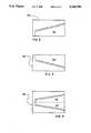
- FIGS. 2-4are examples of the screen displays of the display shown in the embodiment in FIG. 1.
- FIG. 1an embodiment of the invention is shown in which there is provided a system for inspection of a part comprising: a first camera 2 and a second camera 2', which are separated each from the other by a distance d1. Also shown is a part 4 to be measured.
- cameras 2 and 2'comprise video cameras having 1:1.7, 35 mm lenses 3 and 3'.
- One acceptable lensis the Fujinon HF35A-2 ASSY MEDIUM RESOLUTION AS-CLRS-010.
- fields of view 20 and 20'are associated with cameras 2 and 2', respectively.
- Cameras 2 and 2'are connected to computer 6 (for example, an edge detector system such as the ITRAN Dimension Sensor DS20 or DS21) via cables 8 and 8' (for example ITRAN cable CA-XCP).
- Computer 6comprises I/O port 10, memory 12, and processor 14, interconnected as is known to those of skill in the art.
- display 22Also connected to computer 6 is display 22, connected as known to those of skill in the art via cable 24.
- Digitized image 30comprises a side view of part 4 (FIG. 1) in which first portion 32 of part 4 is seen in silhouette, backlit by diffused fluorescent light source 25 (FIG. 1).
- Fluorescent light source 25for example, a Lampi Model 2215 2 ⁇ 15 Wah fixture
- fluorescent tubes 25a and 25bincludes fluorescent tubes 25a and 25b, and has blockers 26 and 26' to reduce reflections from part 4, thereby improving the contrast between portion 32 and the background in image 30 (FIG. 2).
- a polarizeris used to reduce reflections, as is known to those of skill in the art.
- digitized image 30'corresponds to field of view 20' and shows second portion 32' of part 4.
- FIG. 4shows digitized image 34, which is created by splitting the screen of display 22 and pasting image 30 and 30' together.
- First portion 32 and second portion 32'in this application of the invention, show opposite sides of a tapered threaded pipe (part 4), mapped by computer 6 (FIG. 1), wherein each coordinate of the mapping corresponds to a pixel on display 22.
- each pixelis further sub-divided into 32 sub-pixels, and each coordinate corresponds to a sub-pixel.
- Such mapping and screen splittingmay be done by various processes, for example, as described in U.S. Pat. No. 4,581,762, incorporated herein by reference.
- U.S. Pat. No. 4,581,762describes a visual inspection process using certain edge detection routines which allow comparison of distances, angles and other spacial relationships of parts seen by one camera in one field of view.
- edge detection routineswhich allow comparison of distances, angles and other spacial relationships of parts seen by one camera in one field of view.
- the use of one light receiver (for example a camera) to image the entire part 4 as described in U.S. Pat. No. 4,581,762is not useful for inspection, because the part is too large.
- the present inventionprovides a plurality of cameras (in the example shown, camera 2 and 2'), and the digitized image of each is shown on a split screen as seen in FIG. 4.
- computer 6(FIG. 1) has no dimensional data for that portion 27 of part 4 that is not within either field of view 20 or 20'. Therefore, after computer 6 pastes coordinates generated in the mapping of fields of view 20 and 20' together, calculations from the pasted set of coordinates, it made as described by U.S. Pat. No. 4,581,762, will be in error. Therefore, the present invention provides for a correction factor (for example, a constant) calculated from the distance d1 between the centers 29 and 29' of the focal planes of cameras 2 and 2'. According to one embodiment of the invention, such a correction factor is entered via computer 19 and keyboard 16, connected via cable 18. The correction factor is derived by measuring the difference on a manual scale, or, alternatively, by any means for automatically calculation of the distance d1 and entering the value to computer 6.
- a correction factorfor example, a constant
- edge detector measurement techniquesallow edge detector measurement techniques to be used on large parts which could not be measured according to earlier techniques (such as those described in U.S. Pat. No. 4,581,762) due to the poor resolution, and therefore the poor accuracy of single camera applications.
Landscapes
- Physics & Mathematics (AREA)
- General Physics & Mathematics (AREA)
- Engineering & Computer Science (AREA)
- Multimedia (AREA)
- Signal Processing (AREA)
- Length Measuring Devices By Optical Means (AREA)
Abstract
Description
The present invention relates to vision inspection systems and processes which determine interrelationships between dimensions of parts to be inspected.
Mechanical tolerance testing of parts (for example, testing of threaded members by ring gauges, taper gauges, lead gauges, thread gauges, rulers and scales) have been used for years. Slip gauges and other apperati (for example, the AccuThread® gauge by Coulter Services, Inc; Actis® by TuboScope, Inc; MRP® gauges by gagemaker, Inc.) have also been used. Finally, visual inspection systems have recently been used for inspection of parts such as bolts coming off of assembly lines, as described in U.S. Pat. No. 4,581,762, incorporated by reference.
A common failing of all of the above mechanical measurement processes and devices is the inability to measure a wide variety of differently sized parts. For example, for each threaded size pipe to be measured, a different size gauge must be on hand to measure the various parameters required (examples of the parameters to be measured include pitch diameter, ovality, lead, taper, thread height, and L4 (the distance from the end of the pen to the last visible thread). Visual inspection systems have been limited by the resolution of the imaging techniques applied. For example, a wide angle lens, (which is capable of including a large device in its field of view) has less resolution than a more narrow angle lens, when both are set at the same distance from the object to the image. Increased fields of view can be accomplished by backing up narrow angle lens, but again, resolution is compromised.
Accordingly, there is a need for a measurement process system which is accurate over a wide variety of sizes and shapes of parts. There is also a need for the resolution achieved in visual inspection systems using narrow angle cameras in inspection of large parts (for example, oil field pipe threads).
According to one embodiment of the invention, there is provided a process for inspection of a part comprising the steps of: mapping a first portion of the part; mapping a second portion of the part; defining a first reference coordinate corresponding to a first reference point located on the first portion of the part; defining a second reference coordinate corresponding to a second reference point located on the second portion of the part; determining the number of coordinates between the first reference coordinate and the second reference coordinate; calculating a constant corresponding to third portion of the part, wherein the third portion of the part is not mapped; and adding the constant to the number of coordinates between the first and the second reference coordinates.
According to one aspect of the invention, the process further comprises backlighting the part with a light source; wherein the mapping of the first portion comprises: capturing the image of the first portion with a first camera; defining a first field of view which partially comprises a first image of the first portion of the part and light emitted from the light source, wherein the first portion blocks at least part of the light, creating different light intensities in differing areas of the first field of view; dividing the first field view into a first set of coordinates; assigning a coordinate intensity value to each of the first set of coordinates, wherein the coordinate intensity value of each coordinate corresponds to the light intensity at each coordinate within the first field of view; and displaying the light intensity value of each coordinate of the first set within a first portion of a display. The mapping of the second portion comprises: capturing the image of the second portion with a second camera; defining a second field of view which partially comprises a second image of the first portion of the part and light emitted from the light source, wherein the second portion blocks at least part of the light, creating different light intensities in differing areas of the second field of view; dividing the second field view into a second set of coordinates; assigning a coordinate intensity value to each of the second set of coordinates, wherein the coordinate intensity value of each coordinate corresponds to the light intensity at each coordinate within the second field of view; and displaying the light intensity value of each coordinate of the second set within a second portion of the display. The calculating comprises: determining the distance between the focal plane of the first camera and the focal plane of the second camera to provide a camera distance value and scaling the camera distance value to a camera distance coordinate value wherein the camera distance coordinate value equals the constant.
According to a further embodiment of the invention, there is provided a system for inspection of a part comprising: means for mapping a first portion of the part; means for mapping a second portion of the part; means for defining a first reference coordinate corresponding to a first reference point located on the first portion of the part; means for defining a second reference coordinate corresponding to a second reference point located on the second portion of the part; means for determining the number of coordinates between the first reference coordinate and the second reference coordinate; means for calculating a constant corresponding to third portion of the part, wherein the third portion of the part is not mapped; means for adding the constant to the number of coordinates between the first and the second reference coordinates.
According to one aspect of the invention, there is further provided means for backlighting the part with a light source; and wherein said means for mapping of the first portion comprises: means for capturing the image of the first portion with a first camera; means for defining a first field of view which partially comprises a first image of the first portion of the part and light emitted from the light source, wherein the first portion blocks at least part of the light, creating different light intensities in differing areas of the first field of view; means for dividing the first field view into a first set of coordinates; means for assigning a coordinate intensity value to each of the first set of coordinates, wherein the coordinate intensity value of each coordinate corresponds to the light intensity at each coordinate within the first field of view; and means for displaying the light intensity value of each coordinate of the first set within a first portion of a display. The means for mapping of the second portion comprises: means for capturing the image of the second portion with a second camera; means for defining a second field of view which partially comprises a second image of the first portion of the part and light emitted from the light source, wherein the second portion blocks at least part of the light, creating different light intensities in differing areas of the second field of view; means for dividing the second field view into a second set of coordinates; means for assigning a coordinate intensity value to each of the second set of coordinates, wherein the coordinate intensity value of each coordinate corresponds to the light intensity at each coordinate within the second field of view; and means for displaying the light intensity value of each coordinate of the second set within a second portion of the display. The said means for calculating comprises: means for determining the distance between the focal plane of the first camera and the focal plane of the second camera to provide a camera distance value and means for scaling the camera distance value to a camera distance coordinate value wherein the camera distance coordinate value equals the constant.
According to a further embodiment of the invention, there is provided a system for inspection of a part comprising: a computer; a first camera connected to the processor and having a first field of view; a second camera connected to the processor and having a second field of view; and a light source located behind the part; wherein the first field of view includes a first portion of the part; wherein the second field of view includes a second portion of the part; wherein the computer digitizes the first field of view to define a first digitized field of view; wherein the computer digitizes the second field of view to define a second digitized field of view; wherein the computer assigns a set of coordinate address values, one to each coordinate of each of the digitized fields of view; wherein the computer assigns a set of coordinate image values to each coordinate of each of the digitized fields of view; wherein the computer pastes the first and the second digitized fields of view together as if the first and second digitized fields of view were separate halves of the one total field of view, whereby a pasted digitized field of view is defined; wherein the distance in coordinates between any coordinate of the first digitized field of view and the second digitized field of view is corrected by a correction factor; and wherein the correction factor is determined from the distance between the first camera and the second camera.
According to a further embodiment of the invention, there is provided a process for measuring a part comprising: imaging a first portion of the part; imaging a second portion of the part, wherein a third portion located between the first portion of the part and the second portion of the part is not imaged; detecting an edge of the first portion; detecting an edge of the second portion; calculating a measurement value wherein the measurement value is dependant on the relative position of the edge of the first portion and the edge of the second portion; and correcting the measurement value, wherein the correcting is based on the third dimensions of the third portion.
According to a still further embodiment of the invention, there is provided a system for measuring a part comprising: means for imaging a first portion of the part; means for imaging a second portion of the part, wherein a third portion located between the first portion of the part and the second portion of the part is not imaged; means for detecting an edge of the first portion; means for detecting an edge of the second portion; means for calculating a measurement value wherein the measurement value is dependant on the relative position of the edge of the first portion and the edge of the second portion; and means for correcting the measurement value, wherein the correcting is based on the third dimensions of the third portion.
For a more complete understanding of the present invention and for further advantages thereof, reference is made to the following Description of Embodiments of the Invention taken in conjunction with the accompanying Drawings, in which:
FIG. 1 is a side view of an embodiment of the invention, showing the spacial relationships between various components and how those components are interconnected.
FIGS. 2-4 are examples of the screen displays of the display shown in the embodiment in FIG. 1.
It is to be noted, however, that the appended drawings illustrate only typical embodiments of this invention, are not necessarily to scale, and are not to be considered limiting of its scope, for the invention may admit to other equally effective embodiments.
Referring now to FIG. 1 an embodiment of the invention is shown in which there is provided a system for inspection of a part comprising: afirst camera 2 and a second camera 2', which are separated each from the other by a distance d1. Also shown is apart 4 to be measured. According to one embodiment,cameras 2 and 2' comprise video cameras having 1:1.7, 35mm lenses 3 and 3'. One acceptable lens is the Fujinon HF35A-2 ASSY MEDIUM RESOLUTION AS-CLRS-010. Associated withcameras 2 and 2' are fields ofview 20 and 20', respectively.
Referring now to FIG. 2, a digitizedimage 30 is shown as it is seen ondisplay 22 of FIG. 1. Digitizedimage 30 comprises a side view of part 4 (FIG. 1) in whichfirst portion 32 ofpart 4 is seen in silhouette, backlit by diffused fluorescent light source 25 (FIG. 1). Fluorescent light source 25 (for example, a Lampi Model 2215 2×15 Wah fixture) includesfluorescent tubes blockers 26 and 26' to reduce reflections frompart 4, thereby improving the contrast betweenportion 32 and the background in image 30 (FIG. 2). In an alternative embodiment a polarizer is used to reduce reflections, as is known to those of skill in the art.
Referring now to FIG. 3, digitizedimage 30' corresponds to field of view 20' and shows second portion 32' ofpart 4.
FIG. 4 shows digitizedimage 34, which is created by splitting the screen ofdisplay 22 and pastingimage First portion 32 and second portion 32', in this application of the invention, show opposite sides of a tapered threaded pipe (part 4), mapped by computer 6 (FIG. 1), wherein each coordinate of the mapping corresponds to a pixel ondisplay 22. According to an alternative embodiment each pixel is further sub-divided into 32 sub-pixels, and each coordinate corresponds to a sub-pixel. Such mapping and screen splitting may be done by various processes, for example, as described in U.S. Pat. No. 4,581,762, incorporated herein by reference.
U.S. Pat. No. 4,581,762 describes a visual inspection process using certain edge detection routines which allow comparison of distances, angles and other spacial relationships of parts seen by one camera in one field of view. However, in certain applications (for example, inspection of tapered threaded pipe, the use of one light receiver (for example a camera) to image theentire part 4 as described in U.S. Pat. No. 4,581,762, is not useful for inspection, because the part is too large. Accordingly the present invention provides a plurality of cameras (in the example shown,camera 2 and 2'), and the digitized image of each is shown on a split screen as seen in FIG. 4.
According to the present invention, computer 6 (FIG. 1) has no dimensional data for thatportion 27 ofpart 4 that is not within either field ofview 20 or 20'. Therefore, aftercomputer 6 pastes coordinates generated in the mapping of fields ofview 20 and 20' together, calculations from the pasted set of coordinates, it made as described by U.S. Pat. No. 4,581,762, will be in error. Therefore, the present invention provides for a correction factor (for example, a constant) calculated from the distance d1 between thecenters 29 and 29' of the focal planes ofcameras 2 and 2'. According to one embodiment of the invention, such a correction factor is entered viacomputer 19 andkeyboard 16, connected viacable 18. The correction factor is derived by measuring the difference on a manual scale, or, alternatively, by any means for automatically calculation of the distance d1 and entering the value tocomputer 6.
The use of such a correction factor allows edge detector measurement techniques to be used on large parts which could not be measured according to earlier techniques (such as those described in U.S. Pat. No. 4,581,762) due to the poor resolution, and therefore the poor accuracy of single camera applications.
The above described embodiments and aspects of the invention are provided by way of example, and are not intended as limitations on the scope of the invention, as it is foreseen that various embodiments and progressions in the art will practice the present invention.
Claims (15)
1. A process for inspection of a part comprising the steps of:
mapping a first portion of the part;
mapping a second portion of the part;
defining a first reference coordinate corresponding to a first reference point located on the first portion of the part;
defining a second reference coordinate corresponding to a second reference point located on the second portion of the part;
determining the number of coordinates between the first reference coordinate and the second reference coordinate;
calculating a constant corresponding to a third portion of the part, wherein the third portion of the part is not mapped; and
adding the constant to the number of coordinates between the first and the second reference coordinates.
2. A process as in claim 1 further comprising:
capturing the image of the first portion with a first camera;
capturing the image of the second portion with a second camera; and
displaying the image of the first portion and the image of the second portion in different portions of a display.
3. A process as in claim 1 wherein said calculating comprises:
determining the distance between the focal plane of the first camera and the focal plane of the second camera to provide a camera distance value, and
scaling the camera distance value to a camera distance coordinate value wherein the camera distance coordinate value equals the constant.
4. A process as in claim 1 further comprising:
backlighting the part with a light source;
wherein said mapping of the first portion comprises:
capturing the image of the first portion with a first camera;
defining a first field of view which partially comprises
a first image of the first portion of the part and
light emitted from the light source;
wherein the first portion blocks at least part of the light, creating different light intensities in differing areas of the first field of view;
dividing the first field view into a first set of coordinates;
assigning a coordinate intensity value to each of the first set of coordinates, wherein the coordinate intensity value of each coordinate corresponds to the light intensity at each coordinate within the first field of view; and
displaying the light intensity value of each coordinate of the first set within a first portion of a display;
wherein said mapping of the second portion comprises:
capturing the image of the second portion with a second camera;
defining a second field of view which partially comprises
a second image of the first portion of the part and
light emitted from the light source,
wherein the second portion blocks at least part of the light, creating different light intensities in differing areas of the second field of view;
dividing the second field view into a second set of coordinates;
assigning a coordinate intensity value to each of the second set of coordinates, wherein the coordinate intensity value of each coordinate corresponds to the light intensity at each coordinate within the second field of view; and
displaying the light intensity value of each coordinate of the second set within a second portion of the display; and
wherein said calculating comprises:
determining the distance between the focal plane of the first camera and the focal plane of the second camera to provide a camera distance value and
scaling the camera distance value to a camera distance coordinate value wherein the camera distance coordinate value equals the constant.
5. A process as in claim 1 further comprising backlighting the part with a light source.
6. A process as in claim 5 further wherein said mapping of the first portion comprises:
defining a field of view, which partially comprises
a first image of the first portion of the part,
light emitted from the light source, and
wherein the first portion blocks at least part of the light, creating different light intensities in differing areas of the field of view;
dividing the field view into a number of coordinates; and
assigning a coordinate intensity value to each of the coordinates, wherein the coordinate intensity value of each coordinate corresponds to the light intensity at each coordinate within the field of view.
7. A process as in claim 6 further comprising displaying the light intensity value of each coordinate on a display.
8. A system for inspection of a part comprising:
means for mapping a first portion of the part;
means for mapping a second portion of the part;
means for defining a first reference coordinate corresponding to a first reference point located on the first portion of the part;
means for defining a second reference coordinate corresponding to a second reference point located on the second portion of the part;
means for determining the number of coordinates between the first reference coordinate and the second reference coordinate;
means for calculating a constant corresponding to third portion of the part, wherein the third portion of the part is not mapped; and
means for adding the constant to the number of coordinates between the first and the second reference coordinates.
9. A system as in claim 8 further comprising:
means for capturing the image of the first portion with a first camera;
means for capturing the image of the second portion with a second camera; and
means for displaying the image of the first portion and the image of the second portion in different portions of a display.
10. A system as in claim 8 wherein said means for calculating comprises:
means for determining the distance between the focal plane of the first camera and the focal plane of the second camera to provide a camera distance value and
means for scaling the camera distance value to a camera distance coordinate value wherein the camera distance coordinate value equals the constant.
11. A system as in claim 8 further comprising:
means for backlighting the part with a light source; and
wherein said means for mapping of the first portion comprises:
means for capturing the image of the first portion with a first camera;
means for defining a first field of view which partially comprises:
a first image of the first portion of the part and
light emitted from the light source,
wherein the first portion blocks at least part of the light, creating different light intensities in differing areas the first field of view;
means for dividing the first field view into a first set of coordinates;
means for assigning a coordinate intensity value to each of the first set of coordinates, wherein the coordinate intensity value of each coordinate corresponds to the light intensity at each coordinate within the first field of view; and
means for displaying the light intensity value of each coordinate of the first set within a first portion of a display;
wherein said means for mapping of the second portion comprises:
means for capturing the image of the second portion with a second camera;
means for defining a second field of view which partially comprises
a second image of the second portion of the part and
light emitted from the light source,
wherein the second portion blocks at least part of the light, creating different light intensities in differing areas of the second field of view;
means for dividing the second field view into a second set of coordinates;
means for assigning a coordinate intensity value to each of the second set of coordinates, wherein the coordinate intensity value of each coordinate corresponds to the light intensity at each coordinate within the second field of view; and
means for displaying the light intensity value of each coordinate of the second set within a second portion of the display; and
wherein said means for calculating comprises:
means for determining the distance between the focal plane of the first camera and the focal plane of the second camera to provide a camera distance value and
means for scaling the camera distance value to a camera distance coordinate value wherein the camera distance coordinate value equals the constant.
12. A system as in claim 8 further comprising means for backlighting the part with a light source.
13. A process as in claim 12 further wherein said means for mapping of the first portion comprises:
means for defining a field of view which partially comprises:
a first image of the first portion of the part and
light emitted from the light source,
wherein the first portion blocks at least part of the light, creating different light intensities in differing areas of the field of view;
means for dividing the field view into a number of coordinates;
means for assigning a coordinate intensity value to each of the coordinates, wherein the coordinate intensity value of each coordinate corresponds to the light intensity at each coordinate within the field of view.
14. A system as in claim 13 further comprising means for displaying the light intensity value of each coordinate on a display.
15. A system for inspection of a part comprising:
a computer;
a first camera connected to the computer and having a first field of view;
a second camera connected to the computer and having a second field of view; and
a light source located such that the part is between said first camera and said light source;
wherein the first field of view includes a first portion of the part;
wherein the second field of view includes a second portion of the part;
wherein the computer digitizes the first field of view to define a first digitized field of view;
wherein the computer digitizes the second field of view to define a second digitized field of view;
wherein the computer assigns a set of coordinate address values, one to each coordinate of each of the digitized fields of view;
wherein the computer assigns a set of coordinate image values to each coordinate of each of the digitized fields of view;
wherein the computer pastes the first and the second digitized fields of view together as if the first and second digitized fields of view were separate halves of the one total field of view, whereby a pasted digitized field of view is defined;
wherein the distance in coordinates between any coordinate of the first digitized field of view and the second digitized field of view is corrected by a correction factor; and
wherein the correction factor is determined from the distance between the first camera and the second camera.
Priority Applications (1)
| Application Number | Priority Date | Filing Date | Title |
|---|---|---|---|
| US07/792,813US5260780A (en) | 1991-11-15 | 1991-11-15 | Visual inspection device and process |
Applications Claiming Priority (1)
| Application Number | Priority Date | Filing Date | Title |
|---|---|---|---|
| US07/792,813US5260780A (en) | 1991-11-15 | 1991-11-15 | Visual inspection device and process |
Publications (1)
| Publication Number | Publication Date |
|---|---|
| US5260780Atrue US5260780A (en) | 1993-11-09 |
Family
ID=25158146
Family Applications (1)
| Application Number | Title | Priority Date | Filing Date |
|---|---|---|---|
| US07/792,813Expired - Fee RelatedUS5260780A (en) | 1991-11-15 | 1991-11-15 | Visual inspection device and process |
Country Status (1)
| Country | Link |
|---|---|
| US (1) | US5260780A (en) |
Cited By (19)
| Publication number | Priority date | Publication date | Assignee | Title |
|---|---|---|---|---|
| US5519826A (en)* | 1994-04-29 | 1996-05-21 | Atari Games Corporation | Stop motion animation system |
| US5608405A (en)* | 1995-10-06 | 1997-03-04 | Lockheed Martin Corporation | Method of generating visual representation of terrain height from SAR data employing multigrid analysis |
| US5751342A (en)* | 1995-11-22 | 1998-05-12 | Samsung Display Devices Co., Ltd. | Visual inspection system for a product |
| US5926268A (en)* | 1996-06-04 | 1999-07-20 | Inex, Inc. | System and method for stress detection in a molded container |
| US6097427A (en)* | 1996-03-29 | 2000-08-01 | Ethicon, Inc. | Method of and apparatus for detecting defects in a process for making sealed sterile packages |
| US6809756B1 (en) | 1999-01-22 | 2004-10-26 | Honeywell Oy | System for monitoring a process |
| EP1624279A1 (en)* | 2004-08-06 | 2006-02-08 | Axalto SA | System and method for contactless measuring of the dimensions of an opaque object |
| US20110238199A1 (en)* | 2008-12-05 | 2011-09-29 | Tenaris Connections Limited | Measurement method and device for thread parameters |
| US20110295550A1 (en)* | 2010-06-01 | 2011-12-01 | Tenaris Connections Limited | Measuring device of thread parameters for threaded joints |
| US8182422B2 (en) | 2005-12-13 | 2012-05-22 | Avantis Medical Systems, Inc. | Endoscope having detachable imaging device and method of using |
| US8197399B2 (en) | 2006-05-19 | 2012-06-12 | Avantis Medical Systems, Inc. | System and method for producing and improving images |
| US8235887B2 (en) | 2006-01-23 | 2012-08-07 | Avantis Medical Systems, Inc. | Endoscope assembly with retroscope |
| US8289381B2 (en) | 2005-01-05 | 2012-10-16 | Avantis Medical Systems, Inc. | Endoscope with an imaging catheter assembly and method of configuring an endoscope |
| US8287446B2 (en) | 2006-04-18 | 2012-10-16 | Avantis Medical Systems, Inc. | Vibratory device, endoscope having such a device, method for configuring an endoscope, and method of reducing looping of an endoscope |
| US8744160B2 (en) | 2010-06-01 | 2014-06-03 | Tenaris Connections Limited | Systems and methods for measurement of geometrical parameters of threaded joints |
| US8797392B2 (en)* | 2005-01-05 | 2014-08-05 | Avantis Medical Sytems, Inc. | Endoscope assembly with a polarizing filter |
| US8872906B2 (en) | 2005-01-05 | 2014-10-28 | Avantis Medical Systems, Inc. | Endoscope assembly with a polarizing filter |
| US9044185B2 (en) | 2007-04-10 | 2015-06-02 | Avantis Medical Systems, Inc. | Method and device for examining or imaging an interior surface of a cavity |
| US20150241303A1 (en)* | 2014-02-26 | 2015-08-27 | Siemens Energy, Inc. | Method for inspecting a turbine engine rotor with a thru bolt threads inspection apparatus |
Citations (5)
| Publication number | Priority date | Publication date | Assignee | Title |
|---|---|---|---|---|
| US4135817A (en)* | 1978-03-09 | 1979-01-23 | The United States Of America As Represented By The Administrator Of The National Aeronautics And Space Administration | Apparatus for measuring an aircraft's speed and height |
| US4520389A (en)* | 1982-03-16 | 1985-05-28 | Windmoller & Holscher | Method of mounting printing blocks in correct positions on form cylinders of flexographic printing machines for multicolor printing |
| US4581762A (en)* | 1984-01-19 | 1986-04-08 | Itran Corporation | Vision inspection system |
| US4644394A (en)* | 1985-12-31 | 1987-02-17 | Dale Reeves | Apparatus for inspecting an externally threaded surface of an object |
| US4727179A (en)* | 1984-03-29 | 1988-02-23 | Deutsche Gesellschaft Fur Wiederaufarbeitung Von Kernbrennstoffen Mbh | Method and apparatus for position control of plant parts in a highly radioactive cell for an atomic plant |
- 1991
- 1991-11-15USUS07/792,813patent/US5260780A/ennot_activeExpired - Fee Related
Patent Citations (5)
| Publication number | Priority date | Publication date | Assignee | Title |
|---|---|---|---|---|
| US4135817A (en)* | 1978-03-09 | 1979-01-23 | The United States Of America As Represented By The Administrator Of The National Aeronautics And Space Administration | Apparatus for measuring an aircraft's speed and height |
| US4520389A (en)* | 1982-03-16 | 1985-05-28 | Windmoller & Holscher | Method of mounting printing blocks in correct positions on form cylinders of flexographic printing machines for multicolor printing |
| US4581762A (en)* | 1984-01-19 | 1986-04-08 | Itran Corporation | Vision inspection system |
| US4727179A (en)* | 1984-03-29 | 1988-02-23 | Deutsche Gesellschaft Fur Wiederaufarbeitung Von Kernbrennstoffen Mbh | Method and apparatus for position control of plant parts in a highly radioactive cell for an atomic plant |
| US4644394A (en)* | 1985-12-31 | 1987-02-17 | Dale Reeves | Apparatus for inspecting an externally threaded surface of an object |
Cited By (29)
| Publication number | Priority date | Publication date | Assignee | Title |
|---|---|---|---|---|
| US5519826A (en)* | 1994-04-29 | 1996-05-21 | Atari Games Corporation | Stop motion animation system |
| US5608405A (en)* | 1995-10-06 | 1997-03-04 | Lockheed Martin Corporation | Method of generating visual representation of terrain height from SAR data employing multigrid analysis |
| US5751342A (en)* | 1995-11-22 | 1998-05-12 | Samsung Display Devices Co., Ltd. | Visual inspection system for a product |
| US6097427A (en)* | 1996-03-29 | 2000-08-01 | Ethicon, Inc. | Method of and apparatus for detecting defects in a process for making sealed sterile packages |
| US5926268A (en)* | 1996-06-04 | 1999-07-20 | Inex, Inc. | System and method for stress detection in a molded container |
| US6809756B1 (en) | 1999-01-22 | 2004-10-26 | Honeywell Oy | System for monitoring a process |
| EP1624279A1 (en)* | 2004-08-06 | 2006-02-08 | Axalto SA | System and method for contactless measuring of the dimensions of an opaque object |
| US8289381B2 (en) | 2005-01-05 | 2012-10-16 | Avantis Medical Systems, Inc. | Endoscope with an imaging catheter assembly and method of configuring an endoscope |
| US8797392B2 (en)* | 2005-01-05 | 2014-08-05 | Avantis Medical Sytems, Inc. | Endoscope assembly with a polarizing filter |
| US8872906B2 (en) | 2005-01-05 | 2014-10-28 | Avantis Medical Systems, Inc. | Endoscope assembly with a polarizing filter |
| US8182422B2 (en) | 2005-12-13 | 2012-05-22 | Avantis Medical Systems, Inc. | Endoscope having detachable imaging device and method of using |
| US11529044B2 (en) | 2005-12-13 | 2022-12-20 | Psip Llc | Endoscope imaging device |
| US10045685B2 (en) | 2006-01-23 | 2018-08-14 | Avantis Medical Systems, Inc. | Endoscope |
| US8235887B2 (en) | 2006-01-23 | 2012-08-07 | Avantis Medical Systems, Inc. | Endoscope assembly with retroscope |
| US8287446B2 (en) | 2006-04-18 | 2012-10-16 | Avantis Medical Systems, Inc. | Vibratory device, endoscope having such a device, method for configuring an endoscope, and method of reducing looping of an endoscope |
| US8197399B2 (en) | 2006-05-19 | 2012-06-12 | Avantis Medical Systems, Inc. | System and method for producing and improving images |
| US8310530B2 (en) | 2006-05-19 | 2012-11-13 | Avantis Medical Systems, Inc. | Device and method for reducing effects of video artifacts |
| US8587645B2 (en) | 2006-05-19 | 2013-11-19 | Avantis Medical Systems, Inc. | Device and method for reducing effects of video artifacts |
| US9044185B2 (en) | 2007-04-10 | 2015-06-02 | Avantis Medical Systems, Inc. | Method and device for examining or imaging an interior surface of a cavity |
| US9613418B2 (en) | 2007-04-10 | 2017-04-04 | Avantis Medical Systems, Inc. | Method and device for examining or imaging an interior surface of a cavity |
| US10354382B2 (en) | 2007-04-10 | 2019-07-16 | Avantis Medical Systems, Inc. | Method and device for examining or imaging an interior surface of a cavity |
| US8682465B2 (en) | 2008-12-05 | 2014-03-25 | Tenaris Connections Limited | Measurement method and device for thread parameters |
| US20110238199A1 (en)* | 2008-12-05 | 2011-09-29 | Tenaris Connections Limited | Measurement method and device for thread parameters |
| US8855965B2 (en)* | 2010-06-01 | 2014-10-07 | Tenaris Connections Limited | Measuring device of thread parameters for threaded joints |
| US8744160B2 (en) | 2010-06-01 | 2014-06-03 | Tenaris Connections Limited | Systems and methods for measurement of geometrical parameters of threaded joints |
| US20110295550A1 (en)* | 2010-06-01 | 2011-12-01 | Tenaris Connections Limited | Measuring device of thread parameters for threaded joints |
| US10197387B2 (en) | 2010-06-01 | 2019-02-05 | Tenaris Connections B.V. | Measuring device for thread parameters for threaded joints |
| US20150241303A1 (en)* | 2014-02-26 | 2015-08-27 | Siemens Energy, Inc. | Method for inspecting a turbine engine rotor with a thru bolt threads inspection apparatus |
| US9494487B2 (en)* | 2014-02-26 | 2016-11-15 | Siemens Energy, Inc. | Method for inspecting a turbine engine rotor with a thru bolt threads inspection apparatus |
Similar Documents
| Publication | Publication Date | Title |
|---|---|---|
| US5260780A (en) | Visual inspection device and process | |
| US5930383A (en) | Depth sensing camera systems and methods | |
| US5974365A (en) | System for measuring the location and orientation of an object | |
| US6111601A (en) | Non-contacting laser gauge for qualifying screw fasteners and the like | |
| JP2605159B2 (en) | Method and apparatus for observing the inside of an object | |
| US5909285A (en) | Three dimensional inspection system | |
| US5440392A (en) | Method and system for point by point measurement of spatial coordinates | |
| US5563703A (en) | Lead coplanarity inspection apparatus and method thereof | |
| US10054434B2 (en) | Surface roughness measurement device | |
| US6055054A (en) | Three dimensional inspection system | |
| JP3147002B2 (en) | Correction method of distance detection value | |
| CN105783773A (en) | Numerical value calibration method for line structured light vision sensor | |
| US4945490A (en) | Brinell hardness indicator with digital readout | |
| US20200003549A1 (en) | Wire rope measuring device and wire rope measuring method | |
| CN105043304A (en) | Novel calibration plate and calibration method for performing length measurement by using calibration plate | |
| US7679757B1 (en) | Non-contact profile measurement system | |
| CN119246524A (en) | A visual detection information acquisition device and method based on pitch angle calibration image | |
| JP2003269931A (en) | Solid form detector for defects | |
| JPH09264719A (en) | Measuring method and device for screw element | |
| JPS6230904A (en) | Position and posture detecting system for object | |
| JPS6256814A (en) | 3D position measurement camera calibration method | |
| CN116465607A (en) | Double-light-path parallax detection system and method | |
| Sinnreich et al. | Optical 3D tube measurement system for quality control in industry | |
| JPH01242905A (en) | Method for measuring actual size of visual device | |
| Braggins | Achieving sub‐pixel precision |
Legal Events
| Date | Code | Title | Description |
|---|---|---|---|
| AS | Assignment | Owner name:THREADMASTERS, INC. A TX CORPORATION Free format text:ASSIGNMENT OF ASSIGNORS INTEREST.;ASSIGNOR:STAUDT, JOHN J., III;REEL/FRAME:005914/0451 Effective date:19911115 | |
| REMI | Maintenance fee reminder mailed | ||
| FPAY | Fee payment | Year of fee payment:4 | |
| SULP | Surcharge for late payment | ||
| AS | Assignment | Owner name:CENTRAX INTERNATIONAL CORP., TEXAS Free format text:CHANGE OF NAME;ASSIGNOR:DJ INSPECTION SERVICES, INC.;REEL/FRAME:008579/0162 Effective date:19930315 Owner name:DJ INSPECTION SERVICES, INC., TEXAS Free format text:ASSIGNMENT OF ASSIGNORS INTEREST;ASSIGNOR:THREADMASTERS, INC.;REEL/FRAME:008579/0150 Effective date:19920311 | |
| REMI | Maintenance fee reminder mailed | ||
| LAPS | Lapse for failure to pay maintenance fees | ||
| STCH | Information on status: patent discontinuation | Free format text:PATENT EXPIRED DUE TO NONPAYMENT OF MAINTENANCE FEES UNDER 37 CFR 1.362 | |
| FP | Lapsed due to failure to pay maintenance fee | Effective date:20011109 |