US5260709A - Autonomous precision weapon delivery using synthetic array radar - Google Patents
Autonomous precision weapon delivery using synthetic array radarDownload PDFInfo
- Publication number
- US5260709A US5260709AUS07/810,630US81063091AUS5260709AUS 5260709 AUS5260709 AUS 5260709AUS 81063091 AUS81063091 AUS 81063091AUS 5260709 AUS5260709 AUS 5260709A
- Authority
- US
- United States
- Prior art keywords
- target
- weapon
- navigation
- sar
- platform
- Prior art date
- Legal status (The legal status is an assumption and is not a legal conclusion. Google has not performed a legal analysis and makes no representation as to the accuracy of the status listed.)
- Expired - Lifetime
Links
- 238000000034methodMethods0.000claimsabstractdescription28
- 230000008685targetingEffects0.000claimsabstractdescription21
- 238000004422calculation algorithmMethods0.000claimsabstractdescription15
- 238000012545processingMethods0.000claimsdescription7
- 238000012546transferMethods0.000claimsdescription6
- 230000002596correlated effectEffects0.000claimsdescription2
- 230000009466transformationEffects0.000claimsdescription2
- 238000013507mappingMethods0.000claims4
- 238000005259measurementMethods0.000abstractdescription33
- 230000014509gene expressionEffects0.000description13
- 230000005540biological transmissionEffects0.000description6
- 230000008569processEffects0.000description6
- 238000010586diagramMethods0.000description5
- 230000008901benefitEffects0.000description4
- 230000002411adverseEffects0.000description3
- 238000001514detection methodMethods0.000description3
- 239000013598vectorSubstances0.000description3
- 208000004350StrabismusDiseases0.000description2
- 230000001133accelerationEffects0.000description2
- 238000013459approachMethods0.000description2
- 230000008859changeEffects0.000description2
- 230000000875corresponding effectEffects0.000description2
- 230000000694effectsEffects0.000description2
- 230000008030eliminationEffects0.000description2
- 238000003379elimination reactionMethods0.000description2
- 239000005433ionosphereSubstances0.000description2
- 230000001360synchronised effectEffects0.000description2
- 239000005436troposphereSubstances0.000description2
- 230000015556catabolic processEffects0.000description1
- 238000006731degradation reactionMethods0.000description1
- 230000001934delayEffects0.000description1
- 238000009795derivationMethods0.000description1
- 238000011161developmentMethods0.000description1
- 238000003384imaging methodMethods0.000description1
- -1rainSubstances0.000description1
- 238000000926separation methodMethods0.000description1
- 239000000779smokeSubstances0.000description1
- 238000010809targeting techniqueMethods0.000description1
- 238000000844transformationMethods0.000description1
Images


Classifications
- G—PHYSICS
- G01—MEASURING; TESTING
- G01S—RADIO DIRECTION-FINDING; RADIO NAVIGATION; DETERMINING DISTANCE OR VELOCITY BY USE OF RADIO WAVES; LOCATING OR PRESENCE-DETECTING BY USE OF THE REFLECTION OR RERADIATION OF RADIO WAVES; ANALOGOUS ARRANGEMENTS USING OTHER WAVES
- G01S13/00—Systems using the reflection or reradiation of radio waves, e.g. radar systems; Analogous systems using reflection or reradiation of waves whose nature or wavelength is irrelevant or unspecified
- F—MECHANICAL ENGINEERING; LIGHTING; HEATING; WEAPONS; BLASTING
- F41—WEAPONS
- F41G—WEAPON SIGHTS; AIMING
- F41G7/00—Direction control systems for self-propelled missiles
- F41G7/007—Preparatory measures taken before the launching of the guided missiles
- F—MECHANICAL ENGINEERING; LIGHTING; HEATING; WEAPONS; BLASTING
- F41—WEAPONS
- F41G—WEAPON SIGHTS; AIMING
- F41G7/00—Direction control systems for self-propelled missiles
- F41G7/34—Direction control systems for self-propelled missiles based on predetermined target position data
- F41G7/346—Direction control systems for self-propelled missiles based on predetermined target position data using global navigation satellite systems, e.g. GPS, GALILEO, GLONASS
- F—MECHANICAL ENGINEERING; LIGHTING; HEATING; WEAPONS; BLASTING
- F41—WEAPONS
- F41G—WEAPON SIGHTS; AIMING
- F41G7/00—Direction control systems for self-propelled missiles
- F41G7/34—Direction control systems for self-propelled missiles based on predetermined target position data
- F41G7/36—Direction control systems for self-propelled missiles based on predetermined target position data using inertial references
Definitions
- the present inventionrelated to guidance systems, and more particularly, to a method and apparatus for providing autonomous precision guidance of airborne weapons.
- the inventioncomprises a system and method that uses a differential computation of position relative to a launching aircraft and then computes an optimum weapon flight path to guide a weapon payload to a non-moving fixed or relocatable target.
- the inventioncomprises a radar platform having synthetic array radar (SAR) capability.
- the weaponcomprises an inertial navigational system (INS) and is adapted to guide itself to a target position. Since the weapon does not require its own seeker to locate the target, or a data link, the weapon is relatively inexpensive.
- the present inventionuses the radar to locate the desired targets, so that long standoff ranges can be achieved. Once the weapon is launched with the appropriate target coordinates, it operates autonomously, providing for launch-and-leave capability.
- the targeting techniqueemploys the SAR radar on board the launching aircraft (or an independent targeting aircraft). Operator designations of the target in two or more SAR images of the target area are combined into a single target position estimate.
- the target position estimateis placed in the weapon's coordinate frame. Once provided the target position coordinates, the weapon can, with sufficient accuracy in its navigation system (GPS aided navigation is preferred), guide itself to the target with high accuracy and with no need for a homing terminal seeker or data link.
- the present inventionrelies on a very stable coordinate system to be used as a radar reference.
- One good exampleis the performance provided by the GPS navigational system.
- the GPS navigational systemuses four widely spaced satellites.
- the GPS receiveruses time of arrival measurements on a coded waveform to measure the range to each of the four satellites.
- the receiverprocesses the data to calculate its position relative to the earth.
- Most position errorsare caused by non-compensated errors in the models for transmission media (ionosphere and troposphere). If the GPS receiver moves a small distance, the media transmission errors are still approximately the same; therefore the GPS receiver can measure that distance change very accurately.
- the position and velocity estimates for the launching aircraft carrying a GPS receiverexperiences very little drift over a period of several minutes or more. This stability is more difficult and expensive to achieve with other navigation systems.
- the SAR radarmeasures the coordinates of the target relative to the launching aircraft. Therefore, the target position is known in the same coordinate frame as the radar. If the weapon's navigation system is synchronized and matched with the radar's navigation system reference, the target position is also in the weapon's coordinate system.
- An effective way of synchronizing the radar reference and the weapon navigation systemis to use GPS receivers on the weapon and in the launching aircraft. If the weapon is commanded to operate using the same GPS constellation (nominally four satellites) as the radar, the weapon will navigate in the same coordinate frame as the radar (and the target) without requiring a transfer align sequence between the aircraft and the weapon INS. This use of relative, or differential, GPS eliminates the position bias inherent in the GPS system.
- the accuracy requirements of the INS components on the weaponare less stringent and therefore less expensive.
- this approachcan be used for an inertially-guided weapon without GPS aiding and provide approximately equivalent performance.
- the radarcomputes the range and range rate of that pixel relative to the aircraft at some time. Since the radar does not know the altitude difference between the target and the platform, the target may not be in the image plane of the SAR map. As a result, the target's horizontal position in the SAR image may not correspond to its true horizontal position. Although the range and range rate are computed correctly, altitude uncertainty results in a potentially incorrect estimate of the target's horizontal position. The present invention removes this error by computing a flight path in the vicinity of the ground plane which causes the weapon to pass through the correct target point independent of the altitude error.
- the present inventionthus provides a highly accurate but relatively inexpensive weapon system. It has a launch-and-leave capability that enables a pilot to perform other duties (such as designating other targets) instead of weapon guidance.
- the launch-and-leave capability of the present inventionrequires only that the pilot designate the target on a SAR image once; the weapon system performs the remainder of the functions without further pilot intervention. The pilot can then designate other targets on the same image or other images and multiple weapons may be launched simultaneously. The pilot can then exit the target area.
- the present inventiontherefore provides fully autonomous, all-weather, high precision weapon guidance while achieving a very low weapon cost.
- High precision weapon guidanceis provided by the unique differential guidance technique (if a sufficiently accurate and stable navigation system is used).
- the present inventionprovides for a weapon targeting and delivery technique which (1) is very accurate (10-20 ft. CEP (Circular Error Probability)); (2) suffers no degradation in performance or utility in adverse weather conditions (smoke, rain, fog, etc.); (3) is applicable to non-moving relocatable targets (no extensive mission planning required); (4) supports a launch and leave (autonomous) weapon; (5) supports long stand-off range; (6) may be applied to glide or powered weapons; and (7) requires a relatively inexpensive weapon.
- CEPChemical Error Probability
- FIG. 1is a diagram illustrating a weapon guidance system in accordance with the principles of the present invention shown in an operational environment;
- FIG. 2is a block diagram of the system architecture of the system of FIG. 1;
- FIG. 3shows the terminal weapon guidance path computed in accordance with the principles of the present invention
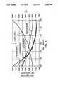
- FIG. 4shows an example of the performance that is achievable with the system of the present invention for a 50 nautical mile range to a target.
- FIG. 1is a diagram illustrating a weapon delivery system 10 in accordance with the principles of the present invention, shown in an operational environment.
- the weapon delivery system 10is shown employed in conjunction with the global positioning system (GPS) 11 that employs four satellites 12a-12d that are used to determine the position of an airborne platform 13, or aircraft 13, having a deployable weapon 14.
- GPSglobal positioning system
- Both the aircraft 13 and the deployable weapon 14have compatible inertial guidance systems (shown in FIG. 2) that are used to control the flight of the weapon 14.
- the aircraft 13flies over the earth, and a non-moving target 15 is located thereon.
- the aircraft 13has a synthetic array radar (SAR) 16 that maps a target area 17 on the earth in the vicinity of the target 15. This is done a plurality of times to produce multiple SAR maps 18a, 18b of the target area 17.
- SARsynthetic array radar
- the weapon 14is launched and flies a trajectory 19 to the target area 17 that is computed in accordance with the present invention.
- Global positioning satellite system data 20GPS data 20
- Inertial reference data derived from the global positioning satellite system 11is transferred to the weapon 14 prior to launch along with target flight path data that directs the weapon 14 to the target 15.
- FIG. 2is a block diagram of the system architecture of the weapon delivery system 10 of FIG. 1.
- the weapon delivery system 10comprises the following subsystems.
- a radar targeting system 16that includes a SAR mode execution subsystem 31 that comprises electronics that is adapted to process radar data to generate a SAR image.
- the SAR mode execution subsystem 31is coupled to a target designation subsystem 32 that comprises electronics that is adapted to permit an operator to select a potential target located in the SAR image.
- the target designation subsystem 32is coupled to a SAR map selection subsystem 33 that determines the number of additional maps that are required for target position computation.
- the SAR map selection subsystem 33is coupled to a map matching subsystem 34 that automatically ensures that subsequent SAR maps 18b are correlated to the first SAR map 18a, so that the target designated in each subsequent map 18b is the same target designated in the first map 18a.
- the map matching subsystem 34is coupled to a target position computation subsystem 35 that computes the target position and the optimum flight path 19 to the target 15 that should be flown by the weapon 14.
- a support function subsystem 36is provided that provides for automated target cueing 37 and precision map matching 38, whose outputs are respectively coupled to the target designation subsystem 32 and the target position computation subsystem 35.
- a navigation subsystem 39is provided that comprises a GPS receiver 40 that receives data from the global positioning system 11, an inertial measuring unit (IMU) 42 that measures aircraft orientation and accelerations, and a Kalman filter 41 that computes the platform's position and velocity. The output of the Kalman filter 41 is coupled to the target position computation subsystem 35.
- the system on the aircraft 13couples pre-launch data such as target position, the GPS satellites to use, Kalman filter initialization parameters and weapon flight path information 43 to the weapon 14 prior to its launch.
- the weapon 14comprises a weapon launch subsystem 51 that is coupled to a navigation and guidance unit 52 that steers the weapon 14 to the target 15.
- a navigation subsystem 55is provided that comprises a GPS receiver 53 that receives data from the global positioning system 11, an inertial measuring unit (IMU) 56 that measures weapon orientation and accelerations, and a Kalman filter 54 that computes the weapon's position and velocity.
- the output of the Kalman filter 54is coupled to the navigation and guidance unit 52 that guides the weapon 14 to the target 15.
- the present weapon delivery system 10relies on a stable coordinate system that is used as the radar reference.
- One good exampleis the performance provided by the GPS navigational system 11.
- the GPS navigational system 11uses the four widely spaced satellites 12a-12d.
- the GPS receiver 40 in the aircraft 13uses time of arrival measurements on a coded waveform to measure the range to each of the four satellites 12a-12d.
- the receiver 40processes the data to calculate its position on the earth. Most of the errors in position are caused by noncompensated errors in the models for the transmission mediums (ionosphere and troposphere). If the GPS receiver 40 moves a small distance, the medium transmission errors are still approximately the same; therefore the GPS receiver 40 can measure that distance change very accurately. As a result, the position and velocity estimates for the aircraft 13 carrying the GPS receiver 40 experiences very little drift over a period of several minutes or more. This stability is more difficult and expensive to achieve with other navigation systems.
- the radar targeting system 16computes the coordinates of the target 15 relative to the aircraft 13. Therefore, the target 15 position is known in the same coordinate frame that the radar 16 uses.
- the weapon's navigation system 55is synchronized and matched with the radar's navigation system 39, and therefore the position of the target 15 will also be in the weapon's coordinate system.
- An effective way of synchronizing the radar's navigation system 39 and the weapon's navigation system 55is to command the weapon to operate using the same GPS constellation (nominally four satellites 12a-12d) as the radar, the weapon 14 then will navigate in the same coordinate frame as the radar 16 (and the target 15). This use of relative, or differential GPS eliminates the position bias inherent in the GPS system.
- the radar targeting system 16computes the range and range rate of that pixel relative to the aircraft 13 at some time. Since the radar targeting system 16 does not know the altitude difference between the target 15 and the platform 13, the target 15 may not be in the image plane of the SAR map 18. As a result, the target's horizontal position in the SAR image 18 may not correspond to its true horizontal position. Although the range and range rate are computed correctly, altitude uncertainty results in a potentially incorrect estimate of the target's horizontal position. The present invention removes this error by computing a flight path 19 in the vicinity of the ground plane which causes the weapon 14 to pass through the true target 15 plane independent of the altitude error.
- the target estimation algorithmoptimally combines the radar measurements with navigation estimates to arrive at the target location in the radar's navigation coordinate system.
- the weapon delivery system 10uses the stability of the GPS navigational system 11 to provide accurate platform location for weapon delivery.
- the GPS navigational system 11is comprised of four widely spaced satellites 12a-12d that broadcast coded transmissions used by the aircraft's GPS receiver 40 to compute the aircraft location and velocity with great precision. While the GPS navigational system 11 provides position measurements with a very small variance, the position bias may be significant. However, most of the bias in GPS position estimates are caused by uncompensated errors in the atmospheric models. If the GPS receiver 40 traverses small distances (e.g., 40 nautical miles), the effects of the atmospheric transmission delays remain relatively constant. Therefore, the GPS receiver 40 can determine its location in the biased coordinate frame with great precision.
- the weapon delivery system 10may use the GPS system 11 to provide highly accurate targeting and weapon delivery.
- FIG. 1shows the typical targeting and weapon launch sequence for the weapon delivery system 10.
- the operatorperforms a high resolution SAR map 18a (approximately 10 feet) of the target area 17.
- the operatordesignates the target 15 with a cursor.
- the operatorperforms one or more additional maps 18b of the target area 17 from a different geometric orientation.
- the weapon delivery system 10automatically correlates the additional map 18b (or maps) with the initial map 18a used for target designation.
- the target position information from all the mapsis used by the model (computational process) to compute a more precise target location in the relative GPS coordinate system.
- only one additional map 18bis necessary to provide sufficient target position accuracy for the high precision weapon delivery.
- the operatorthen launches the weapon 14 against the designated target 15.
- the navigation and guidance unit 52 in the weapon 14guides it on the optimum flight path 19 to ensure accuracy.
- the first and primary feature of the weapon delivery system 10is its autonomous, all-weather weapon delivery capability. This feature alone provides many benefits over conventional weapon delivery systems. Once the weapon 14 is launched, no post-launch aircraft support is necessary to ensure accurate weapon delivery.
- the second major feature of the weapon delivery system 10is the elimination of the need for weapons 14 containing sensors. The elimination of sensors allows substantial financial savings in weapon costs.
- the third major feature of the weapon delivery system 10is that the operator (pilot) is required to designate the target 15 only once. This not only reduces pilot workload and allows the pilot to maintain situational awareness, but also reduces errors caused by not designating the same point in subsequent maps.
- a fourth feature of the weapon delivery system 10is its versatility.
- the weapon delivery system 10may be used to deliver guide bombs or air to ground missiles, for example.
- a fifth benefit of the weapon delivery system 10is its differential GPS guidance algorithm. Since the weapon 14 is guided using a GPS aided navigational system 11, an all weather precision accuracy of 10-15 ft is achievable. A more accurate weapon 14 allows the use of smaller, less expensive warheads which allows the platform 13 to carry more of them and enhance mission capability.
- the block diagram of the weapon delivery system 10is shown in FIG. 2. This figure outlines the functional elements of the weapon delivery system 10 as well as the operational procedure necessary to use the system 10.
- the weapon delivery system 10requires three basic elements. These three elements include the GPS satellite system 11, the radar targeting system 16, and the weapon 14 containing a GPS aided navigation system 55. These aspects of the weapon delivery system 10 are described in greater detail below.
- the GPS satellite system 11is comprised of the four satellites 12a-12d which broadcast coded waveforms which allow the GPS receivers 40, 53 in the aircraft 13 and in the weapon 14 to compute their locations in the GPS coordinate frame.
- the SAR platform 13, or aircraft 13contains a GPS aided navigation subsystem 39 and a radar targeting system 16 with a high-resolution SAR capability.
- the SAR platform 13detects the target 15 and computes the weapon flight path 19 to deliver the weapon 14 to the target 15.
- the weapon 14receives pre-launch target position information from the SAR platform 13 and uses its own GPS aided navigation system 55 to autonomously navigate to the target location.
- the operation of the weapon delivery system 10is comprised of seven basic steps.
- the first stepis target detection. As the SAR platform 13 approaches the target area 17, the operator commands the SAR mode to perform a high resolution map 18a of the desired target area 17.
- the second stepis target designation. Once the operator has verified that the detected target 15 is a target of interest, the operator designates the target 15 with a cursor.
- the third stepis to acquire additional SAR maps 18b of the target from different target angles. These additional maps allow the weapon delivery system 10 to compute the target position more accurately.
- the number of maps necessary to achieve a specific CEP requirementvaries with the geometry at which the SAR maps 18 are obtained. However, in general, only one or two additional maps 18b are required to achieve a 10-15 foot CEP.
- the fourth event in the weapon delivery system 10 operational scenariois map matching.
- the weapon delivery system 10automatically correlates the images of the additional SAR maps 18b with the original SAR map 18a to eliminate the need for repeated operator target designation.
- the fifth stepis to compute the target position and the weapon flight path 19 through that position.
- the target position information from all the mapsis used by the weapon delivery system 10 to compute a more precise target location in the relative GPS coordinate system.
- the sixth stepis comprised of the automatic loading of the pre-launch weapon information.
- the weapon 14receives flight path information, navigation initialization information, and target position information prior to launch.
- the seventh event in the weapon delivery system 10 operational scenariois weapon launch. Once the pre-launch information has been loaded into the weapon 14, the operator is free to launch the weapon 14 against the designated target 15.
- the weapon's GPS aided navigation system 55automatically acquires the same GPS satellites 12a-12d used by the aircraft 13 for navigation and the weapon's navigation and guidance unit 52 then guides the weapon 14 to the target 15 based on the flight path information computed by the SAR platform 13.
- the SAR platform 13contains the GPS aided navigation system 39 for aircraft position and velocity computation as well as the radar targeting system 16 which determines the position of the target 15 with respect to the aircraft 13.
- the processing which occurs on the SAR platform 13may be summarized in five steps: (1) SAR mode execution: initial detection of the desired target 15. (2) Target designation: operator designation of the target of interest. (3) Additional SAR maps: additional SAR maps 18b of target area 17 to provide improved target position accuracy. (4) Automated map matching: automatic matching of additional maps 18 to ensure accurate target designation. (5) Target position computation: computation of target position based on the position and velocity estimates of the aircraft 13 and SAR map measurements. Each of these five processing steps are discussed in detail below.
- the first step in the use of the weapon delivery system 10 in the SAR mode executionprovides the operator with a SAR image of the target area 17.
- the operatormay perform several low resolution maps 18 of the target area 17 before performing a high resolution map of the target 15.
- Only high resolution maps 18 of the target area 17are used as an initial map in the weapon delivery system 10 since small CEPs are desirable for weapon delivery. Therefore, all SAR maps 18 used for targeting typically have pixel sizes of 10 feet or less.
- the operatordesignates the target 15 with a cursor. Although multiple SAR maps 18 are made to ensure precision weapon delivery, the operator only needs to designate the target 15 once.
- a library of target templatesis provided. This target template library, part of the target cueing function 37, provides the operator with an image of what the target 15 should look like and which target pixel should be designated.
- the target cueing function 37provides the templates to assist the operator in targeting and designation.
- the computer-aided target cueing function 37not only aids the operator in designating the correct target 15, but also minimizes the designation error by providing a zoom capability.
- additional high resolution SAR maps of the target 15must be performed to improve the accuracy of the target position computation.
- These addition mapsshould be performed at a different orientation with respect to the target 15. As more maps of the target 15 are obtained from different geometric aspects, the accuracy of the computed position increases.
- Typically only one additional map 18is necessary to achieve a small CEP ( ⁇ 10-15 feet).
- the requisite number of additional maps 18 required to achieve a small CEPwill vary according to a number of factors including target-to-aircraft geometry, SAR map resolution, platform velocity, and platform altitude.
- the weapon delivery system 10performs high precision map matching to accurately locate the same designated target 15 in the additional SAR maps 18.
- the map matching algorithm used to designate the targets 15 in the subsequent imagesis provided by the precision map-matching function 38.
- the high precision map matching function 38automatically determines the coordinate transformations necessary to align the two SAR images. While the accuracy of the matching algorithm may vary with image content and size, subpixel accuracy is possible with images of only modest contrast ratio.
- the target estimation algorithmcombines all of the SAR radar measurements with the aircraft navigation position and velocity estimates to obtain the target location in the relative GPS coordinate system.
- the outputs of the platform's GPS receiver 40 and IMU 42are processed by the Kalman filter 41 and the outputs of the Kalman filter 41 are extrapolated to the time the SAR map 18 was formed to determine the position and velocity vectors to associate with the SAR image data.
- the parameters of the target designated by the operatorare computed in the GPS coordinate system consistent with the GPS system 11.
- the weapon delivery system 10computes an optimal weapon flight path 19 to ensure precise weapon delivery.
- the flight path 19 of the weapon that is computed by the weapon delivery system 10is the best flight path through the estimated target position. If the missile is flown along this path, it is guaranteed to intersect the target plane near the target regardless of the actual altitude of the target, as is illustrated in FIG. 3.
- the weapon delivery system 10downloads the computed flight path into the weapon's navigation and guidance unit 52.
- the system 10also downloads the coefficients necessary for the weapon to initialize its navigation subsystem 55 to eliminate any initial errors between the SAR platform's navigation system 39 and the weapon's navigation system 55.
- the SAR platform 13provides the weapon 14 with information regarding which GPS satellites 12a-12d to use for position computation. Use of the same GPS satellites 12a-12d for aircraft and weapon position determination ensures the same precise differential GPS coordinate system is used for both the weapon 14 and the aircraft 13. Other information the weapon receives prior to launch includes the target position. Once the initialization parameters are received from the SAR platform 13 and the weapon 14 initializes its navigation subsystem 55, the weapon 14 is ready for launch.
- the navigation subsystem 55 in the weapon 14is used by the navigation and guidance computer 52 to guide the weapon 14 along the pre-computed flight path 19 to the target 15.
- no communications between the weapon 14 and the SAR platform 13are necessary.
- the SAR platform 13is free to leave the target area 17.
- the basic error sourcesmust first be identified.
- the first setare the errors associated with the radar targeting system 16. These errors include errors in the aircraft position and velocity data from the navigation system 39, errors in the radar measurements (range and range rate) from the SAR mode 31, and errors associated with the designation function 32.
- the second set of errorsare associated with the navigation and guidance errors of the weapon 14.
- the navigation errorsare associated with incorrect position estimates of the weapon's navigation subsystem 55.
- the guidance errorsare associated with not guiding the weapon 14 along the correct flight path 19 (e.g., due to wind) by the navigation and guidance unit 52 of the weapon 14.
- the accuracy of the weapon delivery system 10may be analyzed.
- the accuracy of the weapon delivery system 10also depends upon the accuracy of the designation and the weapon's ability to navigate to the target 15 along the computed flight path 19. The more measurements that are made, the lower the variance of the estimated target position.
- each SAR target position measurementis optimally combined in a filter to exploit the full benefits of multiple target detections.
- FIG. 4shows the targeting performance of the weapon delivery system 10 when the SAR platform 13 is flying in a straight line path toward the target 15 from an initial range of 50 nautical miles and squint angle of 20 degrees.
- the horizontal axisrepresents the elapsed time for the last measurement since the first SAR map 18 was performed (measurements are made at equal angles).
- the speed of the aircraft 13is assumed to be 750 feet per second and the altitude is 45,000 feet.
- the left vertical axisrepresents the squint angle in degrees or the ground range to the target 15 in nautical miles.
- the right vertical axisrepresents the CEP in feet.
- the performance of FIG. 4assumes the following values for the error sources:
- the radar range rate measurement error ⁇ r 2 (n)is given by ##EQU1## where r(n) is the range at time n.
- the radar range rate measurement erroris ##EQU2## where v(n) is the range rate at time n, the designation error is 4 feet (CEP), the weapon navigation error is 5 feet (CEP), and the weapon guidance error is 3 feet (CEP).
- the weapon delivery system 10can achieve a 14 foot CEP by making a second measurement 5 minutes after the first. At this point the aircraft 13 has flown through an angle of 40 degrees and is 20 nautical miles from the target. Making more than two measurements does not improve the CEP very much. The time required to make these extra measurements is better utilized by imaging other target areas. Performance of this weapon delivery system 10 depends only on the location of the SAR platform 13 relative to the target 15 when the measurements are made and is independent of the aircraft flight path used to get the SAR platform 13 to those measurement locations.
- the target estimation algorithmoptimally combines the radar measurements with the navigation estimates to arrive at the target location in the radar's navigation coordinate system.
- the algorithmconsists of two parts: (1) Compute the horizontal target position for a fixed ground plane; and (2) Generalize the horizontal position for a variable ground plane.
- the first part of the algorithmassumes the target is in a chosen ground plane such as the image plane.
- An estimate of the target (x,y) position in this ground planeis determined by a weighted least squares algorithm using each of the radar measurements.
- the (x t , y t ) (z tdefines the ground plane) value that minimizes the following function is used as this estimate.
- R e (n)⁇ [x(n)-x t ] 2 +[y(n)-y t ] 2 +[z(n)-z t ] 2
- V e (n)v x (n) [x(n)-x t ]+v y (n) [y(n)-y t ]+v z (n) [z(n)-z t ]
- Nis the number of radar measurements performed
- x(n), y(n) and z(n)is the estimated navigation position vector at time n
- v y (n) and v z (n)is the estimated navigation velocity vector at time n
- r(n)is the measured range to the target at time n
- v(n)is the measured range rate to the target at time n
- ⁇ 1 (n) and ⁇ 2 (n)are the weights used for each radar measurement.
- the variance of the first termis used as the first weight.
- the varianceis computed by expanding the first term in a Taylor series around the mean of the random variables. Notationally, a vertical line to the right of an expression in the following equations indicates that the expression is to be evaluated at the mean of each of the variables in that expression. ##EQU5## where x(n) the mean of x(n), y(n) is the mean of y(n), z(n) the mean of z(n), and r(n) is the mean of r(n).
- ⁇ x 2 (n)is the variance of x(n)
- ⁇ y 2 (n)is the variance of y(n)
- ⁇ z 2 (n)is the variance of z(n)
- ⁇ r 2 (n)is the variance of r(n).
- the second termuses the radar range rate measurement, v(n).
- the variance of the second termis used as the second weight. It is computed by expanding the second term in a Taylor series around the mean of each of the random variables. ##EQU7##
- ⁇ v .sbsb.x 2 (n)is the variance of v x (n)
- ⁇ v .sbsb.y 2 (n)is the variance of v y (n)
- ⁇ v .sbsb.z 2 (n)is the variance of v z (n)
- ⁇ r 2 (n)is the variance of v(n).
- the initial value for (x c , y c )is determined by the target position in the first map (each pixel has an x-y coordinate value in the ground plane).
- the solution (x t , y t )is then used for (x c , y c ) on the next iteration. The process is repeated until the derivatives a x and a y are very close to zero.
- the second part of the algorithminvolves finding the best estimates (x t , y t ) as a function of z t . This curve defines the best flight path through the point determined in the first part of this algorithm that will minimize the target miss distance in the true target plane. The radar measurements and navigation estimates are again used to find this path.
- the derivatives of a x and a y with respect to z tneed to be computed.
- the variables a x and a yare a function of all the measured variables as well as x t , y t and z t .
- the measured variablesare assumed to be independent of each other and therefore do not vary as a function of z t .
- the chain rule for derivativesis used to calculate the total derivatives of a x and a y with respect to z t as follows: ##EQU20##
- the first derivatives of a x and a y with respect to z tare computed using equations 1 and 2 respectively.
- the first derivatives of a 11 , a 22 and a 12 with respect to z tare calculated using the chain rule for derivatives. ##EQU29##
- the second derivatives of a x and a y with respect to z tare computed using equations 5 and 6 respectively.
- the first derivatives of a 11 , a 22 and a 12 with respect to z tare computed using equations 9, 10 and 11 respectively.
- the second derivatives of a 11 , a 22 and a 12 with respect to z tare calculated using the chain rule for derivatives. ##EQU37##
- the coefficients associated with the linear termsare computed using equations 3 and 4.
- the coefficients associated with the quadratic termsare computed using equations 7 and 8 and the coefficients associated with the cubic terms are computed using equations 12 and 13.
- the target miss distanceis determined by finding the intersection of the line with the true target plane.
- the weapon impact pointcan be determined by substituting the true target altitude for z and solving for x and y.
- the miss distanceis then equal to the separation between the weapon impact point and the true target x-y in the true target plane.
Landscapes
- Engineering & Computer Science (AREA)
- Chemical & Material Sciences (AREA)
- Combustion & Propulsion (AREA)
- General Engineering & Computer Science (AREA)
- Radar, Positioning & Navigation (AREA)
- Remote Sensing (AREA)
- Computer Networks & Wireless Communication (AREA)
- Physics & Mathematics (AREA)
- General Physics & Mathematics (AREA)
- Radar Systems Or Details Thereof (AREA)
- Aiming, Guidance, Guns With A Light Source, Armor, Camouflage, And Targets (AREA)
- Navigation (AREA)
- Complex Calculations (AREA)
- Feedback Control In General (AREA)
- Position Fixing By Use Of Radio Waves (AREA)
Abstract
Description
Term (2)=v.sub.x (n)[x(n)-x.sub.t ]+v.sub.y (n) [y(n)-y.sub.t ]+v.sub.z (n) [z(n)-z.sub.t ]-v(n) R.sub.e (n)
σ.sub.2.sup.2 (n)=(|Velocity|.sup.2 -v(n).sup.2) σ.sub.p.sup.2 +r(n).sup.2 (σ.sub.v.sup.2 +σ.sub.r.sup.2 (n))
a.sub.11 (x.sub.t -x.sub.c)+a.sub.12 (y.sub.t -y.sub.c)+a.sub.x =0
a.sub.12 (x.sub.t -x.sub.c)+a.sub.22 (y.sub.t -y.sub.c)+a.sub.y =0
Claims (13)
Priority Applications (9)
| Application Number | Priority Date | Filing Date | Title |
|---|---|---|---|
| US07/810,630US5260709A (en) | 1991-12-19 | 1991-12-19 | Autonomous precision weapon delivery using synthetic array radar |
| IL10418192AIL104181A (en) | 1991-12-19 | 1992-12-18 | Autonomous weapon targeting and guidance system using satellite array |
| EP92121647AEP0547637B1 (en) | 1991-12-19 | 1992-12-18 | Autonomous precision weapon delivery using synthetic array radar |
| ES92121647TES2098433T3 (en) | 1991-12-19 | 1992-12-18 | RELEASE AUTONOMOUS PRECISION WEAPON USING A SYNTHETIC NET RADAR. |
| CA002085847ACA2085847C (en) | 1991-12-19 | 1992-12-18 | Autonomous precision weapon delivery using synthetic array radar |
| DE69218143TDE69218143T2 (en) | 1991-12-19 | 1992-12-18 | Autonomous precision weapon firing using a synthetic aperture radar |
| KR1019920024847AKR960014821B1 (en) | 1991-12-19 | 1992-12-19 | Autonomous precision weapon delivery system and method using synthetic array radar |
| JP4356214AJP2525539B2 (en) | 1991-12-19 | 1992-12-21 | Autonomous accuracy weapons using synthetic array rader |
| AU30326/92AAU640091B1 (en) | 1991-12-19 | 1992-12-21 | Autonomous precision weapon delivery using synthetic array radar |
Applications Claiming Priority (1)
| Application Number | Priority Date | Filing Date | Title |
|---|---|---|---|
| US07/810,630US5260709A (en) | 1991-12-19 | 1991-12-19 | Autonomous precision weapon delivery using synthetic array radar |
Publications (1)
| Publication Number | Publication Date |
|---|---|
| US5260709Atrue US5260709A (en) | 1993-11-09 |
Family
ID=25204290
Family Applications (1)
| Application Number | Title | Priority Date | Filing Date |
|---|---|---|---|
| US07/810,630Expired - LifetimeUS5260709A (en) | 1991-12-19 | 1991-12-19 | Autonomous precision weapon delivery using synthetic array radar |
Country Status (9)
| Country | Link |
|---|---|
| US (1) | US5260709A (en) |
| EP (1) | EP0547637B1 (en) |
| JP (1) | JP2525539B2 (en) |
| KR (1) | KR960014821B1 (en) |
| AU (1) | AU640091B1 (en) |
| CA (1) | CA2085847C (en) |
| DE (1) | DE69218143T2 (en) |
| ES (1) | ES2098433T3 (en) |
| IL (1) | IL104181A (en) |
Cited By (59)
| Publication number | Priority date | Publication date | Assignee | Title |
|---|---|---|---|---|
| US5397079A (en)* | 1992-10-16 | 1995-03-14 | Deutsche Aerospace Ag | Process for the autonomous positional control of guided missiles |
| US5424742A (en)* | 1992-12-31 | 1995-06-13 | Raytheon Company | Synthetic aperture radar guidance system and method of operating same |
| US5424743A (en)* | 1994-06-01 | 1995-06-13 | U.S. Department Of Energy | 2-D weighted least-squares phase unwrapping |
| US5430445A (en)* | 1992-12-31 | 1995-07-04 | Raytheon Company | Synthetic aperture radar guidance system and method of operating same |
| US5554994A (en)* | 1995-06-05 | 1996-09-10 | Hughes Missile Systems Company | Self-surveying relative GPS (global positioning system) weapon guidance system |
| US5647558A (en)* | 1995-02-14 | 1997-07-15 | Bofors Ab | Method and apparatus for radial thrust trajectory correction of a ballistic projectile |
| US5657947A (en)* | 1994-08-24 | 1997-08-19 | Loral Corp. | Precision guidance system for aircraft launched bombs |
| DE19703736A1 (en)* | 1996-03-22 | 1997-11-06 | Joao R Dr Ing Moreira | Flight guidance system for aircraft |
| US5809457A (en)* | 1996-03-08 | 1998-09-15 | The United States Of America As Represented By The Administrator Of The National Aeronautics And Space Administration | Inertial pointing and positioning system |
| US5832187A (en)* | 1995-11-03 | 1998-11-03 | Lemelson Medical, Education & Research Foundation, L.P. | Fire detection systems and methods |
| US5943009A (en)* | 1997-02-27 | 1999-08-24 | Abbott; Anthony Steven | GPS guided munition |
| US5963653A (en)* | 1997-06-19 | 1999-10-05 | Raytheon Company | Hierarchical information fusion object recognition system and method |
| WO2000003193A1 (en)* | 1998-07-09 | 2000-01-20 | Raytheon Company | Geographically limited missile |
| US6021374A (en)* | 1997-10-09 | 2000-02-01 | Mcdonnell Douglas Corporation | Stand alone terrain conflict detector and operating methods therefor |
| US6142411A (en)* | 1997-06-26 | 2000-11-07 | Cobleigh; Nelson E. | Geographically limited missile |
| US6157875A (en)* | 1998-07-17 | 2000-12-05 | The United States Of America As Represented By The Secretary Of The Navy | Image guided weapon system and method |
| US6166679A (en)* | 1999-01-13 | 2000-12-26 | Lemelson Jerome H. | Friend or foe detection system and method and expert system military action advisory system and method |
| US6237496B1 (en) | 1997-02-26 | 2001-05-29 | Northrop Grumman Corporation | GPS guided munition |
| US6300898B1 (en)* | 1998-04-16 | 2001-10-09 | Arthur J. Schneider | Airborne GPS guidance system for defeating multiple jammers |
| US6455828B1 (en)* | 1998-06-25 | 2002-09-24 | Lfk-Lenkflugkorpersysteme Gmbh | Method for remote controlled combat of near-surface and/or surface targets |
| US6481666B2 (en) | 2000-04-04 | 2002-11-19 | Yaacov Frucht | Method and system for guiding submunitions |
| US6556895B2 (en)* | 2000-06-05 | 2003-04-29 | Rafael-Armament Development Authority Ltd. | Method for transfer alignment of an inertial measurement unit in the presence of unknown aircraft measurements delays |
| US6573486B1 (en)* | 2002-02-22 | 2003-06-03 | Northrop Grumman Corporation | Projectile guidance with accelerometers and a GPS receiver |
| US6691947B2 (en)* | 2002-03-12 | 2004-02-17 | The Boeing Company | Repetitive image targeting system |
| US6779752B1 (en)* | 2003-03-25 | 2004-08-24 | Northrop Grumman Corporation | Projectile guidance with accelerometers and a GPS receiver |
| US20040188561A1 (en)* | 2003-03-28 | 2004-09-30 | Ratkovic Joseph A. | Projectile guidance with accelerometers and a GPS receiver |
| US20050012660A1 (en)* | 2002-11-15 | 2005-01-20 | Lockheed Martin Corporation | All-weather precision guidance and navigation system |
| US6853332B1 (en)* | 2001-07-19 | 2005-02-08 | Bae Systems Plc | Automatic registration of images in digital terrain elevation data |
| US20050030219A1 (en)* | 2002-11-21 | 2005-02-10 | Friedrich William A. | Integration of a semi-active laser seeker into the dsu-33 proximity sensor |
| US20050040280A1 (en)* | 2003-08-19 | 2005-02-24 | Hua Cuong Tu | Multi-sensor guidance system for extreme force launch shock applications |
| US20050211083A1 (en)* | 2004-03-29 | 2005-09-29 | Waid James D | Methods and systems for estimating weapon effectiveness |
| US20060071849A1 (en)* | 2004-09-30 | 2006-04-06 | Lockheed Martin Corporation | Tactical all weather precision guidance and navigation system |
| US20060163422A1 (en)* | 2005-01-26 | 2006-07-27 | Raytheon Company | Pseudo GPS aided multiple projectile bistatic guidance |
| US20070205320A1 (en)* | 2005-02-07 | 2007-09-06 | Zemany Paul D | Optically Guided Munition |
| US20070205319A1 (en)* | 2005-02-07 | 2007-09-06 | Maynard John A | Radiation Homing Tag |
| US20070241227A1 (en)* | 2005-02-07 | 2007-10-18 | Zemany Paul D | Ballistic Guidance Control for Munitions |
| US20080001022A1 (en)* | 2005-10-05 | 2008-01-03 | Raytheon Company | Precision targeting |
| US20080006735A1 (en)* | 2004-08-10 | 2008-01-10 | Asa Fein | Guided missile with distributed guidance mechanism |
| US20080029641A1 (en)* | 2005-02-07 | 2008-02-07 | Bae Systems Information And Electronic Systems | Three Axis Aerodynamic Control of Guided Munitions |
| US20080093498A1 (en)* | 2006-03-01 | 2008-04-24 | Leal Michael A | Multiple Kill Vehicle (MKV) Interceptor with Autonomous Kill Vehicles |
| US20080127814A1 (en)* | 2003-05-23 | 2008-06-05 | Mckendree Thomas L | method of providing integrity bounding of weapons |
| WO2008045582A3 (en)* | 2006-02-01 | 2008-11-06 | Raytheon Co | Multiple kill vehicle (mkv) interceptor and method for intercepting exo and endo-atmospheric targets |
| US20090039197A1 (en)* | 2005-02-07 | 2009-02-12 | Bae Systems Information And Electronic Systems Integration Inc. | Optically Guided Munition Control System and Method |
| EP2133648A1 (en)* | 2008-04-10 | 2009-12-16 | LFK-Lenkflugkörpersysteme GmbH | Unmanned missile and method of flight control |
| US20100270418A1 (en)* | 2008-02-21 | 2010-10-28 | Mbda Uk Limited | Missile training system |
| US20110233322A1 (en)* | 2010-03-24 | 2011-09-29 | Lfk-Lenkflugkoerpersysteme Gmbh | Navigation Method for a Missile |
| US8076622B1 (en)* | 2009-08-31 | 2011-12-13 | Rockwell Collins, Inc. | Low profile, conformal global positioning system array for artillery |
| US8237096B1 (en) | 2010-08-19 | 2012-08-07 | Interstate Electronics Corporation, A Subsidiary Of L-3 Communications Corporation | Mortar round glide kit |
| US8513580B1 (en)* | 2012-06-26 | 2013-08-20 | The United States Of America As Represented By The Secretary Of The Navy | Targeting augmentation for short-range munitions |
| US8525088B1 (en)* | 2012-03-21 | 2013-09-03 | Rosemont Aerospace, Inc. | View-point guided weapon system and target designation method |
| US8558153B2 (en)* | 2009-01-23 | 2013-10-15 | Raytheon Company | Projectile with inertial sensors oriented for enhanced failure detection |
| US8610041B1 (en)* | 2011-05-23 | 2013-12-17 | Lockheed Martin Corporation | Missile tracking by GPS reflections |
| US10078339B2 (en)* | 2013-08-15 | 2018-09-18 | Rafael Advanced Defense Systems Ltd | Missile system with navigation capability based on image processing |
| US10387727B2 (en)* | 2017-09-13 | 2019-08-20 | Wing Aviation Llc | Backup navigation system for unmanned aerial vehicles |
| US10571224B2 (en)* | 2015-05-04 | 2020-02-25 | Propagation Research Associates, Inc. | Systems, methods and computer-readable media for improving platform guidance or navigation using uniquely coded signals |
| US11018705B1 (en) | 2020-07-17 | 2021-05-25 | Propagation Research Associates, Inc. | Interference mitigation, target detection, location and measurement using separable waveforms transmitted from spatially separated antennas |
| CN113075653A (en)* | 2021-03-26 | 2021-07-06 | 北京理工大学 | Navigation method and system of aircraft |
| US20230228529A1 (en)* | 2022-01-18 | 2023-07-20 | Rosemount Aerospace Inc. | Constraining navigational drift in a munition |
| US20240128993A1 (en)* | 2022-10-17 | 2024-04-18 | Propagation Research Associates, Inc. | Coordinate Frame Projection Using Multiple Unique Signals Transmitted from a Localized Array of Spatially Distributed Antennas |
Families Citing this family (9)
| Publication number | Priority date | Publication date | Assignee | Title |
|---|---|---|---|---|
| EP0583972A1 (en)* | 1992-08-17 | 1994-02-23 | Texas Instruments Incorporated | Improvements in and relating to precision targeting |
| US5344105A (en)* | 1992-09-21 | 1994-09-06 | Hughes Aircraft Company | Relative guidance using the global positioning system |
| DE4325218C2 (en)* | 1993-07-28 | 1998-10-22 | Diehl Stiftung & Co | Artillery missile and method for increasing the performance of an artillery missile |
| US5432520A (en)* | 1993-10-18 | 1995-07-11 | Hughes Aircraft Company | SAR/GPS inertial method of range measurement |
| US5473331A (en)* | 1994-10-31 | 1995-12-05 | Hughes Aircraft Company | Combined SAR monopulse and inverse monopulse weapon guidance |
| GB2402825B (en)* | 2003-06-12 | 2007-02-14 | Anthony Michael O'doherty | Monitoring system and method |
| KR101362911B1 (en)* | 2012-11-09 | 2014-02-18 | 한국항공우주산업 주식회사 | Ofp system for driving a synthetic aperture radar mounted in the flight and controlling method for the same |
| CN111077767B (en)* | 2019-12-12 | 2021-11-30 | 南京航空航天大学 | Satellite constellation networking same-orbit plane capacity expansion reconstruction control method |
| CN119245437A (en)* | 2024-02-29 | 2025-01-03 | 北京理工大学 | A mid-course guidance method for loitering missiles with time and space constraints |
Citations (18)
| Publication number | Priority date | Publication date | Assignee | Title |
|---|---|---|---|---|
| US4179693A (en)* | 1977-05-23 | 1979-12-18 | Rockwell Internation Corporation | Autonomous, check-pointing, navigational system for an airborne vehicle |
| US4204210A (en)* | 1972-09-15 | 1980-05-20 | The United States Of America As Represented By The Secretary Of The Air Force | Synthetic array radar command air launched missile system |
| US4315609A (en)* | 1971-06-16 | 1982-02-16 | The United States Of America As Represented By The Secretary Of The Navy | Target locating and missile guidance system |
| US4495580A (en)* | 1981-03-30 | 1985-01-22 | E-Systems, Inc. | Navigation system |
| US4549184A (en)* | 1981-06-09 | 1985-10-22 | Grumman Aerospace Corporation | Moving target ordnance control |
| US4578678A (en)* | 1983-11-14 | 1986-03-25 | The United States Of America As Represented By The United States National Aeronautics And Space Administration | High dynamic global positioning system receiver |
| US4589610A (en)* | 1983-11-08 | 1986-05-20 | Westinghouse Electric Corp. | Guided missile subsystem |
| US4613864A (en)* | 1983-01-19 | 1986-09-23 | International Standard Electric Corporation | Position-fixing system |
| US4741245A (en)* | 1986-10-03 | 1988-05-03 | Dkm Enterprises | Method and apparatus for aiming artillery with GPS NAVSTAR |
| US4783744A (en)* | 1986-12-08 | 1988-11-08 | General Dynamics, Pomona Division | Self-adaptive IRU correction loop design interfacing with the target state estimator for multi-mode terminal handoff |
| US4825213A (en)* | 1981-05-15 | 1989-04-25 | Grumman Aerospace Corporation | Simultaneous triple aperture radar |
| US4914734A (en)* | 1989-07-21 | 1990-04-03 | The United States Of America As Represented By The Secretary Of The Air Force | Intensity area correlation addition to terrain radiometric area correlation |
| US4949089A (en)* | 1989-08-24 | 1990-08-14 | General Dynamics Corporation | Portable target locator system |
| US4959656A (en)* | 1989-10-31 | 1990-09-25 | The United States Of America As Represented By The Administrator Of The National Aeronautics And Space Administration | Efficient detection and signal parameter estimation with application to high dynamic GPS receiver |
| US5018218A (en)* | 1988-08-29 | 1991-05-21 | Raytheon Company | Confirmed boundary pattern matching |
| US5047777A (en)* | 1989-05-12 | 1991-09-10 | Dornier Luftfahrt Gmbh | Linear method of navigation |
| US5113193A (en)* | 1985-11-12 | 1992-05-12 | The United States Of America As Represented By The Secretary Of The Air Force | Autonomous synchronization of a bistatic synthetic aperture radar (SAR) system |
| US5175554A (en)* | 1980-12-29 | 1992-12-29 | Raytheon Company | All weather tactical strike system (AWTSS) and method of operation |
Family Cites Families (2)
| Publication number | Priority date | Publication date | Assignee | Title |
|---|---|---|---|---|
| DE3145374C2 (en)* | 1981-11-14 | 1984-12-20 | Messerschmitt-Bölkow-Blohm GmbH, 8000 München | Method and device for combating ground targets by means of missiles |
| DE3932548A1 (en)* | 1989-09-29 | 1991-04-11 | Telefunken Systemtechnik | Torpedo targetting system using GPS - has antenna towed on water surface by line from torpedo |
- 1991
- 1991-12-19USUS07/810,630patent/US5260709A/ennot_activeExpired - Lifetime
- 1992
- 1992-12-18DEDE69218143Tpatent/DE69218143T2/ennot_activeExpired - Lifetime
- 1992-12-18EPEP92121647Apatent/EP0547637B1/ennot_activeExpired - Lifetime
- 1992-12-18ILIL10418192Apatent/IL104181A/ennot_activeIP Right Cessation
- 1992-12-18ESES92121647Tpatent/ES2098433T3/ennot_activeExpired - Lifetime
- 1992-12-18CACA002085847Apatent/CA2085847C/ennot_activeExpired - Lifetime
- 1992-12-19KRKR1019920024847Apatent/KR960014821B1/ennot_activeExpired - Lifetime
- 1992-12-21AUAU30326/92Apatent/AU640091B1/ennot_activeExpired
- 1992-12-21JPJP4356214Apatent/JP2525539B2/ennot_activeExpired - Lifetime
Patent Citations (18)
| Publication number | Priority date | Publication date | Assignee | Title |
|---|---|---|---|---|
| US4315609A (en)* | 1971-06-16 | 1982-02-16 | The United States Of America As Represented By The Secretary Of The Navy | Target locating and missile guidance system |
| US4204210A (en)* | 1972-09-15 | 1980-05-20 | The United States Of America As Represented By The Secretary Of The Air Force | Synthetic array radar command air launched missile system |
| US4179693A (en)* | 1977-05-23 | 1979-12-18 | Rockwell Internation Corporation | Autonomous, check-pointing, navigational system for an airborne vehicle |
| US5175554A (en)* | 1980-12-29 | 1992-12-29 | Raytheon Company | All weather tactical strike system (AWTSS) and method of operation |
| US4495580A (en)* | 1981-03-30 | 1985-01-22 | E-Systems, Inc. | Navigation system |
| US4825213A (en)* | 1981-05-15 | 1989-04-25 | Grumman Aerospace Corporation | Simultaneous triple aperture radar |
| US4549184A (en)* | 1981-06-09 | 1985-10-22 | Grumman Aerospace Corporation | Moving target ordnance control |
| US4613864A (en)* | 1983-01-19 | 1986-09-23 | International Standard Electric Corporation | Position-fixing system |
| US4589610A (en)* | 1983-11-08 | 1986-05-20 | Westinghouse Electric Corp. | Guided missile subsystem |
| US4578678A (en)* | 1983-11-14 | 1986-03-25 | The United States Of America As Represented By The United States National Aeronautics And Space Administration | High dynamic global positioning system receiver |
| US5113193A (en)* | 1985-11-12 | 1992-05-12 | The United States Of America As Represented By The Secretary Of The Air Force | Autonomous synchronization of a bistatic synthetic aperture radar (SAR) system |
| US4741245A (en)* | 1986-10-03 | 1988-05-03 | Dkm Enterprises | Method and apparatus for aiming artillery with GPS NAVSTAR |
| US4783744A (en)* | 1986-12-08 | 1988-11-08 | General Dynamics, Pomona Division | Self-adaptive IRU correction loop design interfacing with the target state estimator for multi-mode terminal handoff |
| US5018218A (en)* | 1988-08-29 | 1991-05-21 | Raytheon Company | Confirmed boundary pattern matching |
| US5047777A (en)* | 1989-05-12 | 1991-09-10 | Dornier Luftfahrt Gmbh | Linear method of navigation |
| US4914734A (en)* | 1989-07-21 | 1990-04-03 | The United States Of America As Represented By The Secretary Of The Air Force | Intensity area correlation addition to terrain radiometric area correlation |
| US4949089A (en)* | 1989-08-24 | 1990-08-14 | General Dynamics Corporation | Portable target locator system |
| US4959656A (en)* | 1989-10-31 | 1990-09-25 | The United States Of America As Represented By The Administrator Of The National Aeronautics And Space Administration | Efficient detection and signal parameter estimation with application to high dynamic GPS receiver |
Cited By (91)
| Publication number | Priority date | Publication date | Assignee | Title |
|---|---|---|---|---|
| US5397079A (en)* | 1992-10-16 | 1995-03-14 | Deutsche Aerospace Ag | Process for the autonomous positional control of guided missiles |
| US5424742A (en)* | 1992-12-31 | 1995-06-13 | Raytheon Company | Synthetic aperture radar guidance system and method of operating same |
| US5430445A (en)* | 1992-12-31 | 1995-07-04 | Raytheon Company | Synthetic aperture radar guidance system and method of operating same |
| US5424743A (en)* | 1994-06-01 | 1995-06-13 | U.S. Department Of Energy | 2-D weighted least-squares phase unwrapping |
| WO1998057114A1 (en)* | 1994-08-24 | 1998-12-17 | Lockheed Martin Corporation | Precision guidance system for aircraft launched bombs |
| US5657947A (en)* | 1994-08-24 | 1997-08-19 | Loral Corp. | Precision guidance system for aircraft launched bombs |
| US5866838A (en)* | 1994-08-24 | 1999-02-02 | Lockheed Martin Corp. | Precision guidance system for aircraft launched bombs |
| US5647558A (en)* | 1995-02-14 | 1997-07-15 | Bofors Ab | Method and apparatus for radial thrust trajectory correction of a ballistic projectile |
| US5554994A (en)* | 1995-06-05 | 1996-09-10 | Hughes Missile Systems Company | Self-surveying relative GPS (global positioning system) weapon guidance system |
| US6289331B1 (en) | 1995-11-03 | 2001-09-11 | Robert D. Pedersen | Fire detection systems using artificial intelligence |
| US5832187A (en)* | 1995-11-03 | 1998-11-03 | Lemelson Medical, Education & Research Foundation, L.P. | Fire detection systems and methods |
| US6556981B2 (en) | 1995-11-03 | 2003-04-29 | Robert D. Pedersen | Fire detection systems and methods |
| US5809457A (en)* | 1996-03-08 | 1998-09-15 | The United States Of America As Represented By The Administrator Of The National Aeronautics And Space Administration | Inertial pointing and positioning system |
| DE19703736C2 (en)* | 1996-03-22 | 1998-04-09 | Joao R Dr Ing Moreira | Method for automating a radar with a synthetic aperture (SAR) and for guiding a carrier in flight, and device for carrying out the method |
| DE19703736A1 (en)* | 1996-03-22 | 1997-11-06 | Joao R Dr Ing Moreira | Flight guidance system for aircraft |
| US6237496B1 (en) | 1997-02-26 | 2001-05-29 | Northrop Grumman Corporation | GPS guided munition |
| US5943009A (en)* | 1997-02-27 | 1999-08-24 | Abbott; Anthony Steven | GPS guided munition |
| US5963653A (en)* | 1997-06-19 | 1999-10-05 | Raytheon Company | Hierarchical information fusion object recognition system and method |
| US6142411A (en)* | 1997-06-26 | 2000-11-07 | Cobleigh; Nelson E. | Geographically limited missile |
| US6021374A (en)* | 1997-10-09 | 2000-02-01 | Mcdonnell Douglas Corporation | Stand alone terrain conflict detector and operating methods therefor |
| US6300898B1 (en)* | 1998-04-16 | 2001-10-09 | Arthur J. Schneider | Airborne GPS guidance system for defeating multiple jammers |
| US6455828B1 (en)* | 1998-06-25 | 2002-09-24 | Lfk-Lenkflugkorpersysteme Gmbh | Method for remote controlled combat of near-surface and/or surface targets |
| WO2000003193A1 (en)* | 1998-07-09 | 2000-01-20 | Raytheon Company | Geographically limited missile |
| US6157875A (en)* | 1998-07-17 | 2000-12-05 | The United States Of America As Represented By The Secretary Of The Navy | Image guided weapon system and method |
| US6166679A (en)* | 1999-01-13 | 2000-12-26 | Lemelson Jerome H. | Friend or foe detection system and method and expert system military action advisory system and method |
| US6201495B1 (en) | 1999-01-13 | 2001-03-13 | Jerome H. Lemelson | Friend or foe detection system and method and expert system military action advisory system and method |
| US6437727B2 (en) | 1999-01-13 | 2002-08-20 | Jerome H. Lemelson | Friend or foe detection system and method and expert system military action advisory system and method |
| US6481666B2 (en) | 2000-04-04 | 2002-11-19 | Yaacov Frucht | Method and system for guiding submunitions |
| US6556895B2 (en)* | 2000-06-05 | 2003-04-29 | Rafael-Armament Development Authority Ltd. | Method for transfer alignment of an inertial measurement unit in the presence of unknown aircraft measurements delays |
| US6853332B1 (en)* | 2001-07-19 | 2005-02-08 | Bae Systems Plc | Automatic registration of images in digital terrain elevation data |
| US6573486B1 (en)* | 2002-02-22 | 2003-06-03 | Northrop Grumman Corporation | Projectile guidance with accelerometers and a GPS receiver |
| US6691947B2 (en)* | 2002-03-12 | 2004-02-17 | The Boeing Company | Repetitive image targeting system |
| US7098846B2 (en)* | 2002-11-15 | 2006-08-29 | Lockheed Martin Corporation | All-weather precision guidance and navigation system |
| US20050012660A1 (en)* | 2002-11-15 | 2005-01-20 | Lockheed Martin Corporation | All-weather precision guidance and navigation system |
| WO2004046748A3 (en)* | 2002-11-15 | 2005-02-10 | Lockheed Corp | All-weather precision guidance and navigation system |
| US20050030219A1 (en)* | 2002-11-21 | 2005-02-10 | Friedrich William A. | Integration of a semi-active laser seeker into the dsu-33 proximity sensor |
| US6919840B2 (en) | 2002-11-21 | 2005-07-19 | Alliant Techsystems Inc. | Integration of a semi-active laser seeker into the DSU-33 proximity sensor |
| US6779752B1 (en)* | 2003-03-25 | 2004-08-24 | Northrop Grumman Corporation | Projectile guidance with accelerometers and a GPS receiver |
| US20040188561A1 (en)* | 2003-03-28 | 2004-09-30 | Ratkovic Joseph A. | Projectile guidance with accelerometers and a GPS receiver |
| US6883747B2 (en)* | 2003-03-28 | 2005-04-26 | Northrop Grumman Corporation | Projectile guidance with accelerometers and a GPS receiver |
| US20080127814A1 (en)* | 2003-05-23 | 2008-06-05 | Mckendree Thomas L | method of providing integrity bounding of weapons |
| US20050040280A1 (en)* | 2003-08-19 | 2005-02-24 | Hua Cuong Tu | Multi-sensor guidance system for extreme force launch shock applications |
| US7032857B2 (en)* | 2003-08-19 | 2006-04-25 | Cuong Tu Hua | Multi-sensor guidance system for extreme force launch shock applications |
| US20050211083A1 (en)* | 2004-03-29 | 2005-09-29 | Waid James D | Methods and systems for estimating weapon effectiveness |
| US7121183B2 (en) | 2004-03-29 | 2006-10-17 | Honeywell International Inc. | Methods and systems for estimating weapon effectiveness |
| US20080006735A1 (en)* | 2004-08-10 | 2008-01-10 | Asa Fein | Guided missile with distributed guidance mechanism |
| US20060071849A1 (en)* | 2004-09-30 | 2006-04-06 | Lockheed Martin Corporation | Tactical all weather precision guidance and navigation system |
| US20060163422A1 (en)* | 2005-01-26 | 2006-07-27 | Raytheon Company | Pseudo GPS aided multiple projectile bistatic guidance |
| US7121502B2 (en)* | 2005-01-26 | 2006-10-17 | Raytheon Company | Pseudo GPS aided multiple projectile bistatic guidance |
| US20070205320A1 (en)* | 2005-02-07 | 2007-09-06 | Zemany Paul D | Optically Guided Munition |
| US7503521B2 (en) | 2005-02-07 | 2009-03-17 | Bae Systems Information And Electronic Systems Integration Inc. | Radiation homing tag |
| US7834300B2 (en) | 2005-02-07 | 2010-11-16 | Bae Systems Information And Electronic Systems Integration Inc. | Ballistic guidance control for munitions |
| US20080029641A1 (en)* | 2005-02-07 | 2008-02-07 | Bae Systems Information And Electronic Systems | Three Axis Aerodynamic Control of Guided Munitions |
| US8450668B2 (en) | 2005-02-07 | 2013-05-28 | Bae Systems Information And Electronic Systems Integration Inc. | Optically guided munition control system and method |
| US20070241227A1 (en)* | 2005-02-07 | 2007-10-18 | Zemany Paul D | Ballistic Guidance Control for Munitions |
| US7533849B2 (en) | 2005-02-07 | 2009-05-19 | Bae Systems Information And Electronic Systems Integration Inc. | Optically guided munition |
| US20070205319A1 (en)* | 2005-02-07 | 2007-09-06 | Maynard John A | Radiation Homing Tag |
| US20090039197A1 (en)* | 2005-02-07 | 2009-02-12 | Bae Systems Information And Electronic Systems Integration Inc. | Optically Guided Munition Control System and Method |
| US20080001022A1 (en)* | 2005-10-05 | 2008-01-03 | Raytheon Company | Precision targeting |
| WO2008057069A3 (en)* | 2005-10-05 | 2009-04-09 | Raytheon Co | Precision targeting |
| US7728264B2 (en)* | 2005-10-05 | 2010-06-01 | Raytheon Company | Precision targeting |
| WO2008045582A3 (en)* | 2006-02-01 | 2008-11-06 | Raytheon Co | Multiple kill vehicle (mkv) interceptor and method for intercepting exo and endo-atmospheric targets |
| US8084724B1 (en) | 2006-02-01 | 2011-12-27 | Raytheon Company | Enhanced multiple kill vehicle (MKV) interceptor for intercepting exo and endo-atmospheric targets |
| US7494090B2 (en)* | 2006-03-01 | 2009-02-24 | Raytheon Company | Multiple kill vehicle (MKV) interceptor with autonomous kill vehicles |
| US20080093498A1 (en)* | 2006-03-01 | 2008-04-24 | Leal Michael A | Multiple Kill Vehicle (MKV) Interceptor with Autonomous Kill Vehicles |
| WO2008066938A3 (en)* | 2006-03-01 | 2008-10-02 | Raytheon Co | Multiple kill vehicle (mkv) interceptor with autonomous kill vehicles |
| US20100270418A1 (en)* | 2008-02-21 | 2010-10-28 | Mbda Uk Limited | Missile training system |
| US8274023B2 (en)* | 2008-02-21 | 2012-09-25 | Mbda Uk Limited | Missile training system |
| EP2133648A1 (en)* | 2008-04-10 | 2009-12-16 | LFK-Lenkflugkörpersysteme GmbH | Unmanned missile and method of flight control |
| US8558153B2 (en)* | 2009-01-23 | 2013-10-15 | Raytheon Company | Projectile with inertial sensors oriented for enhanced failure detection |
| US8076622B1 (en)* | 2009-08-31 | 2011-12-13 | Rockwell Collins, Inc. | Low profile, conformal global positioning system array for artillery |
| US8569669B2 (en)* | 2010-03-24 | 2013-10-29 | Lfk-Lenkflugkoerpersysteme Gmbh | Navigation method for a missile |
| US20110233322A1 (en)* | 2010-03-24 | 2011-09-29 | Lfk-Lenkflugkoerpersysteme Gmbh | Navigation Method for a Missile |
| US8237096B1 (en) | 2010-08-19 | 2012-08-07 | Interstate Electronics Corporation, A Subsidiary Of L-3 Communications Corporation | Mortar round glide kit |
| US8610041B1 (en)* | 2011-05-23 | 2013-12-17 | Lockheed Martin Corporation | Missile tracking by GPS reflections |
| US8525088B1 (en)* | 2012-03-21 | 2013-09-03 | Rosemont Aerospace, Inc. | View-point guided weapon system and target designation method |
| US20130248647A1 (en)* | 2012-03-21 | 2013-09-26 | Rosemount Aerospace Inc. | View-point guided weapon system and target designation method |
| US8513580B1 (en)* | 2012-06-26 | 2013-08-20 | The United States Of America As Represented By The Secretary Of The Navy | Targeting augmentation for short-range munitions |
| US10078339B2 (en)* | 2013-08-15 | 2018-09-18 | Rafael Advanced Defense Systems Ltd | Missile system with navigation capability based on image processing |
| US10571224B2 (en)* | 2015-05-04 | 2020-02-25 | Propagation Research Associates, Inc. | Systems, methods and computer-readable media for improving platform guidance or navigation using uniquely coded signals |
| US11353290B2 (en) | 2015-05-04 | 2022-06-07 | Propagation Research Associates, Inc. | Systems, methods and computer-readable media for improving platform guidance or navigation using uniquely coded signals |
| US10387727B2 (en)* | 2017-09-13 | 2019-08-20 | Wing Aviation Llc | Backup navigation system for unmanned aerial vehicles |
| US10908622B2 (en) | 2017-09-13 | 2021-02-02 | Wing Aviation Llc | Backup navigation system for unmanned aerial vehicles |
| US11656638B1 (en) | 2017-09-13 | 2023-05-23 | Wing Aviation Llc | Backup navigation system for unmanned aerial vehicles |
| US12007792B2 (en) | 2017-09-13 | 2024-06-11 | Wing Aviation Llc | Backup navigation system for unmanned aerial vehicles |
| US11018705B1 (en) | 2020-07-17 | 2021-05-25 | Propagation Research Associates, Inc. | Interference mitigation, target detection, location and measurement using separable waveforms transmitted from spatially separated antennas |
| CN113075653A (en)* | 2021-03-26 | 2021-07-06 | 北京理工大学 | Navigation method and system of aircraft |
| US20230228529A1 (en)* | 2022-01-18 | 2023-07-20 | Rosemount Aerospace Inc. | Constraining navigational drift in a munition |
| US11913757B2 (en)* | 2022-01-18 | 2024-02-27 | Rosemount Aerospace Inc. | Constraining navigational drift in a munition |
| US20240128993A1 (en)* | 2022-10-17 | 2024-04-18 | Propagation Research Associates, Inc. | Coordinate Frame Projection Using Multiple Unique Signals Transmitted from a Localized Array of Spatially Distributed Antennas |
| US12375117B2 (en)* | 2022-10-17 | 2025-07-29 | Propagation Research Associates Llc | Coordinate frame projection using multiple unique signals transmitted from a localized array of spatially distributed antennas |
Also Published As
| Publication number | Publication date |
|---|---|
| DE69218143D1 (en) | 1997-04-17 |
| EP0547637B1 (en) | 1997-03-12 |
| KR930013756A (en) | 1993-07-22 |
| ES2098433T3 (en) | 1997-05-01 |
| JP2525539B2 (en) | 1996-08-21 |
| JPH0688698A (en) | 1994-03-29 |
| CA2085847C (en) | 1996-12-03 |
| DE69218143T2 (en) | 1997-10-09 |
| EP0547637A1 (en) | 1993-06-23 |
| AU640091B1 (en) | 1993-08-12 |
| KR960014821B1 (en) | 1996-10-21 |
| IL104181A (en) | 1995-12-31 |
| CA2085847A1 (en) | 1993-06-20 |
Similar Documents
| Publication | Publication Date | Title |
|---|---|---|
| US5260709A (en) | Autonomous precision weapon delivery using synthetic array radar | |
| US5344105A (en) | Relative guidance using the global positioning system | |
| US4589610A (en) | Guided missile subsystem | |
| US5485384A (en) | On-board navigation system for an aerial craft including a synthetic aperture sideways looking radar | |
| US6157875A (en) | Image guided weapon system and method | |
| US4954837A (en) | Terrain aided passive range estimation | |
| US4168524A (en) | Airborne surveying apparatus and method | |
| US5862496A (en) | Method of computing divert velocity for the ground-based interceptor using numerical partial derivatives | |
| CA2303875A1 (en) | Radio frequency interferometer and laser rangefinder/designator base targeting system | |
| Klotz et al. | GPS-aided navigation and unaided navigation on the joint direct attack munition | |
| US11815335B2 (en) | Guided munition systems for detecting off-axis targets | |
| Ross et al. | A transfer alignment algorithm study based on actual flight test data from a tactical air-to-ground weapon launch | |
| US6211816B1 (en) | Process and apparatus for target or position reconnaissance | |
| US6142412A (en) | Highly accurate long range optically-aided inertially guided type missile | |
| RU2150124C1 (en) | Method for pre-launch setting of high- accuracy missiles | |
| Koch et al. | ATRAN terrain sensing guidance-the grand-daddy system | |
| BOSE | Radar updated strapdown inertial midcourse guidance performance analysis for missiles | |
| RU2117902C1 (en) | Method of target indication by direction for system of guidance of controlled object | |
| Longenbaker | Terrain-aided navigation of an unpowered tactical missile using autopilot-grade sensors | |
| Schmidt et al. | Precision strike concepts exploiting relative GPS techniques | |
| TR2022008668A1 (en) | FLIGHT SIMULATION BASED NAVIGATION METHOD WITH DISTANCE MEASUREMENT SUPPORT | |
| TR2022008667A1 (en) | GLOBAL POSITIONING SYSTEM SUPPORTED FLIGHT SIMULATION BASED NAVIGATION METHOD | |
| Reese et al. | Precision Imaging Strike Technology Integration Laboratory (PISTIL) | |
| Ohlmeyer et al. | Appliation of GPS/INS to Extended-Range Guided Munitions and Tactical Ballistic Missile Interceptors | |
| RITLAND | Survey of aided-inertial navigation systems for missiles |
Legal Events
| Date | Code | Title | Description |
|---|---|---|---|
| AS | Assignment | Owner name:HUGHES AIRCRAFT COMPANY, A CORP. OF DE, CALIFORNIA Free format text:ASSIGNMENT OF ASSIGNORS INTEREST.;ASSIGNOR:NOWAKOWSKI, MICHAEL V.;REEL/FRAME:005998/0498 Effective date:19911218 | |
| STCF | Information on status: patent grant | Free format text:PATENTED CASE | |
| FPAY | Fee payment | Year of fee payment:4 | |
| FPAY | Fee payment | Year of fee payment:8 | |
| FEPP | Fee payment procedure | Free format text:PAYOR NUMBER ASSIGNED (ORIGINAL EVENT CODE: ASPN); ENTITY STATUS OF PATENT OWNER: LARGE ENTITY | |
| AS | Assignment | Owner name:HE HOLDINGS, INC., A DELAWARE CORP., CALIFORNIA Free format text:CHANGE OF NAME;ASSIGNOR:HUGHES AIRCRAFT COMPANY, A CORPORATION OF THE STATE OF DELAWARE;REEL/FRAME:016087/0541 Effective date:19971217 Owner name:RAYTHEON COMPANY, MASSACHUSETTS Free format text:MERGER;ASSIGNOR:HE HOLDINGS, INC. DBA HUGHES ELECTRONICS;REEL/FRAME:016116/0506 Effective date:19971217 | |
| FPAY | Fee payment | Year of fee payment:12 |