US5259954A - Portable intravenous solution preparation apparatus and method - Google Patents
Portable intravenous solution preparation apparatus and methodDownload PDFInfo
- Publication number
- US5259954A US5259954AUS07/809,272US80927291AUS5259954AUS 5259954 AUS5259954 AUS 5259954AUS 80927291 AUS80927291 AUS 80927291AUS 5259954 AUS5259954 AUS 5259954A
- Authority
- US
- United States
- Prior art keywords
- module
- reagent
- module fluid
- quick release
- raw water
- Prior art date
- Legal status (The legal status is an assumption and is not a legal conclusion. Google has not performed a legal analysis and makes no representation as to the accuracy of the status listed.)
- Expired - Lifetime
Links
Images


Classifications
- C—CHEMISTRY; METALLURGY
- C02—TREATMENT OF WATER, WASTE WATER, SEWAGE, OR SLUDGE
- C02F—TREATMENT OF WATER, WASTE WATER, SEWAGE, OR SLUDGE
- C02F1/00—Treatment of water, waste water, or sewage
- C02F1/44—Treatment of water, waste water, or sewage by dialysis, osmosis or reverse osmosis
- C02F1/441—Treatment of water, waste water, or sewage by dialysis, osmosis or reverse osmosis by reverse osmosis
- A—HUMAN NECESSITIES
- A61—MEDICAL OR VETERINARY SCIENCE; HYGIENE
- A61L—METHODS OR APPARATUS FOR STERILISING MATERIALS OR OBJECTS IN GENERAL; DISINFECTION, STERILISATION OR DEODORISATION OF AIR; CHEMICAL ASPECTS OF BANDAGES, DRESSINGS, ABSORBENT PADS OR SURGICAL ARTICLES; MATERIALS FOR BANDAGES, DRESSINGS, ABSORBENT PADS OR SURGICAL ARTICLES
- A61L2/00—Methods or apparatus for disinfecting or sterilising materials or objects other than foodstuffs or contact lenses; Accessories therefor
- A61L2/02—Methods or apparatus for disinfecting or sterilising materials or objects other than foodstuffs or contact lenses; Accessories therefor using physical phenomena
- A61L2/022—Filtration
- B—PERFORMING OPERATIONS; TRANSPORTING
- B01—PHYSICAL OR CHEMICAL PROCESSES OR APPARATUS IN GENERAL
- B01D—SEPARATION
- B01D61/00—Processes of separation using semi-permeable membranes, e.g. dialysis, osmosis or ultrafiltration; Apparatus, accessories or auxiliary operations specially adapted therefor
- B01D61/02—Reverse osmosis; Hyperfiltration ; Nanofiltration
- B01D61/025—Reverse osmosis; Hyperfiltration
- B—PERFORMING OPERATIONS; TRANSPORTING
- B01—PHYSICAL OR CHEMICAL PROCESSES OR APPARATUS IN GENERAL
- B01D—SEPARATION
- B01D61/00—Processes of separation using semi-permeable membranes, e.g. dialysis, osmosis or ultrafiltration; Apparatus, accessories or auxiliary operations specially adapted therefor
- B01D61/02—Reverse osmosis; Hyperfiltration ; Nanofiltration
- B01D61/04—Feed pretreatment
- B—PERFORMING OPERATIONS; TRANSPORTING
- B01—PHYSICAL OR CHEMICAL PROCESSES OR APPARATUS IN GENERAL
- B01D—SEPARATION
- B01D61/00—Processes of separation using semi-permeable membranes, e.g. dialysis, osmosis or ultrafiltration; Apparatus, accessories or auxiliary operations specially adapted therefor
- B01D61/02—Reverse osmosis; Hyperfiltration ; Nanofiltration
- B01D61/08—Apparatus therefor
- B—PERFORMING OPERATIONS; TRANSPORTING
- B01—PHYSICAL OR CHEMICAL PROCESSES OR APPARATUS IN GENERAL
- B01D—SEPARATION
- B01D61/00—Processes of separation using semi-permeable membranes, e.g. dialysis, osmosis or ultrafiltration; Apparatus, accessories or auxiliary operations specially adapted therefor
- B01D61/02—Reverse osmosis; Hyperfiltration ; Nanofiltration
- B01D61/10—Accessories; Auxiliary operations
- B—PERFORMING OPERATIONS; TRANSPORTING
- B01—PHYSICAL OR CHEMICAL PROCESSES OR APPARATUS IN GENERAL
- B01D—SEPARATION
- B01D61/00—Processes of separation using semi-permeable membranes, e.g. dialysis, osmosis or ultrafiltration; Apparatus, accessories or auxiliary operations specially adapted therefor
- B01D61/14—Ultrafiltration; Microfiltration
- B01D61/147—Microfiltration
- B—PERFORMING OPERATIONS; TRANSPORTING
- B01—PHYSICAL OR CHEMICAL PROCESSES OR APPARATUS IN GENERAL
- B01F—MIXING, e.g. DISSOLVING, EMULSIFYING OR DISPERSING
- B01F21/00—Dissolving
- B—PERFORMING OPERATIONS; TRANSPORTING
- B01—PHYSICAL OR CHEMICAL PROCESSES OR APPARATUS IN GENERAL
- B01F—MIXING, e.g. DISSOLVING, EMULSIFYING OR DISPERSING
- B01F21/00—Dissolving
- B01F21/20—Dissolving using flow mixing
- B01F21/22—Dissolving using flow mixing using additional holders in conduits, containers or pools for keeping the solid material in place, e.g. supports or receptacles
- B01F21/221—Dissolving using flow mixing using additional holders in conduits, containers or pools for keeping the solid material in place, e.g. supports or receptacles comprising constructions for blocking or redispersing undissolved solids
- B—PERFORMING OPERATIONS; TRANSPORTING
- B01—PHYSICAL OR CHEMICAL PROCESSES OR APPARATUS IN GENERAL
- B01F—MIXING, e.g. DISSOLVING, EMULSIFYING OR DISPERSING
- B01F21/00—Dissolving
- B01F21/50—Elements used for separating or keeping undissolved material in the mixer
- B01F21/501—Tablet canisters provided with perforated walls, sieves, grids or filters
- B—PERFORMING OPERATIONS; TRANSPORTING
- B01—PHYSICAL OR CHEMICAL PROCESSES OR APPARATUS IN GENERAL
- B01D—SEPARATION
- B01D2311/00—Details relating to membrane separation process operations and control
- B01D2311/04—Specific process operations in the feed stream; Feed pretreatment
- C—CHEMISTRY; METALLURGY
- C02—TREATMENT OF WATER, WASTE WATER, SEWAGE, OR SLUDGE
- C02F—TREATMENT OF WATER, WASTE WATER, SEWAGE, OR SLUDGE
- C02F1/00—Treatment of water, waste water, or sewage
- C02F1/44—Treatment of water, waste water, or sewage by dialysis, osmosis or reverse osmosis
- C02F1/444—Treatment of water, waste water, or sewage by dialysis, osmosis or reverse osmosis by ultrafiltration or microfiltration
Definitions
- the inventionrelates to methods and apparatus for purifying water, and methods and apparatus for preparation of intravenous solutions. More specifically, the invention relates to methods and apparatus for preparing intravenous solutions in the field.
- the first probleminvolves the production of injectable quality water for the preparation of an intravenous solution
- the secondinvolves the storage of such solutions.
- Portable microfiltration apparatusare available for campers which are capable of filtering out most bacteria to a particle size of approximately 0.2 ⁇ m. Water at this purity level is potable but is not suitable for injection to the human body. Therefore, there is no portable ultra filtration device which can produce injectable quality water for use with the above described compartmentalized intravenous mixing bags. As a result, there is no effective way to prepare intravenous solutions in the field in the absence of an injectable quality water source.
- the inventionachieves this object, and other objects and advantages which will become apparent from the description which follows by providing a portable, modular intravenous solution preparation apparatus.
- the apparatusincludes a first module which microfilters and detoxifies raw water from a raw water intake.
- a second moduledeionizes the treated water and removes any remaining biological contaminants from the deionized, detoxified water.
- a third modulecontains a predetermined quantity of reagent to produce the desired intravenous solution which can then be collected in an appropriate receptacle.
- all of the modulesare sterile and a fourth module having a sterilization-filtration capability can be inserted intermediate the consumable reagent module and the receptacle for the intravenous solution.
- Fluid permeable volumetric expansion mechanismsare provided in the third module to compensate for volumetric contraction of the reagent because the reagent in the third module can be a soluble material. Such volumetric compensation is necessary to prevent the formation of voids and channels in the reagent which would otherwise effect the resulting concentration of the intravenous solution.
- other volume compensating mechanismsare provided in the second module to compensate for volumetric changes in an ion exchange stage and in an activated carbon stage.
- a pressure compensating mechanismis provided in the first module to maintain hydraulic pressure in a reverse osmosis stage within a desired range.
- the first modulealso has a substantially buoyant, raw water intake mechanism.
- the mechanismpositions a fluid intake port at a preferred distance below the surface of a water body to avoid clogging with plants and biologicals concentrated at the water surface and to avoid collection of dissolved contaminants which tend to concentrate in the sedimentary layers at the bottom of the body of water. Consequently, the mechanism also positions the fluid intake port away from the bottom where agricultural contaminants such as pesticides and fertilizers, plant and bacterial matter tend to concentrate.
- a final ultra filtration mechanism of a fourth modulecan be positioned between the output of the reagent module and the appropriate intravenous solution receptacle to ensure the sterility of the intravenous solution.
- multiple intravenous solution bagscan be connected to the fluid distribution manifold for preparation of solutions having a low reagent concentration.
- An individual bagcan be isolated by the use of hemostats applied to the manifold branches. Once the selected intravenous bag has been filled, the bag can be separated from the manifold by the application of heated forceps.
- a first, second, third and fourth moduleare interconnected by fluid connection mechanisms which mate only with the appropriate connection mechanism on the appropriate module.
- the modulescannot be arranged in an improper sequence.
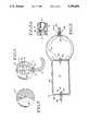
- FIG. 1is an environmental view of the portable intravenous solution preparation apparatus and method in use on a traumatized individual.
- FIG. 2is an isometric view of the first, second, third and fourth modules of the invention.
- FIG. 3is a top plan view of the raw water intake mechanism of the invention with a portion cut away.
- FIG. 4is a side elevational view of the intake mechanism of FIG. 3.
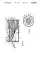
- FIG. 5is a sectional, side elevational view of a pressure generating and pressure regulating stage of the first module of the invention illustrating blockage resistant one-way fluid valves.
- FIG. 5ais an enlarged, sectional, side elevational view of circled area 5a of FIG. 5.
- FIG. 6is a sectional, side elevational view of a microfiltration/reverse osmosis stage of the first module of the invention.
- FIG. 7is a sectional, top elevational view taken along lines 7--7 of FIG. 6.
- FIG. 8is a sectional, side elevational view of a second module of the invention employing an ion exchange chamber and an activated carbon chamber.
- FIG. 9is a sectional, side elevational view of a consumable reagent module prior to use.
- FIG. 10is a sectional, side elevational view of the reagent module shown in FIG. 9 after use.
- FIG. 11is a sectional, side elevational view of the fourth module of the invention illustrating a fluid distribution manifold for multiple intravenous solution bags.
- a portable intravenous solution preparation apparatusin accordance with the principles of the invention is generally indicated at reference numeral 10 in FIGS. 1 and 2.
- the apparatusis preferably modular and includes a potable water maker module 12, an injectable water maker module 14, a reagent module 16, and a sterilization and storage module 18.
- the potable water maker module 12has a raw water strainer 20 which, as best seen in FIG. 1 is substantially buoyant and which serves as an intake for drawing raw water, such as from a pond 22 through an elongated, flexible intake hose 24 and into a pump stage 26 for further processing by the apparatus.
- the apparatusultimately produces an intravenously injectable solution (IV solution) 28 in an intravenous solution bag (IV bag) 30 which may be administered by a qualified medical technician 32 to a patient 34.
- the potable water maker module 12is reusable and has the capacity to process approximately 1,000 liters of raw water before replacement is necessary.
- the raw water which is processed by the potable water maker module 12has sufficient purity for drinking, but is not sufficiently pure for intravenous injection.
- the injectable water maker module 14further processes the potable water emanating from the potable water maker module 12 and produces water sufficient in quality for intravenous injection into the human body and for additional processing in the reagent module 16.
- the reagent modulereacts with the injectable quality water from the injectable water maker module 14 with an appropriate reagent such as calcium chloride, sodium chloride, dextrose, lidocaine hydrochloride, dopamine hydrochloride, alcohol, or various combinations thereof to produce an intravenous solution of the proper concentration.
- the intravenous solutionthen passes through a final sterility filter 36 before entering the IV solution bag 30.
- the IV solution bagis connected to the sterility filter by a medical grade quarter-inch diameter polyvinyl chloride (PVC) outlet tube 38 which can be severed and cauterized by a pair of heated forceps to separate the IV bag 30 from the sterility filter 36.
- PVCpolyvinyl chloride
- each of the moduleshave respective fluid inlets and outlets which are mechanically connectable only to the appropriate inlet or outlet of the appropriate module.
- the systemcan be assembled in the field under exigent circumstances without the possibility of mismatching the modules or connecting the modules out of sequence.
- the systemhas been constructed in a modular fashion so that modules which have a relatively long life cycle (such as the potable water maker module 12 which has a life cycle of approximately 1,000 liters) will not have to be discarded when, for example, a reagent module 16 is exhausted (a reagent module typically will only produce one liter of solution) or if a component such as the injectable water maker module 14 malfunctions prematurely (this module should have a life cycle of more than 1,000 liters).
- the system 10is therefore well adapted for use in the field because a minimum quantity of stock on hand need be maintained.
- various different reagent modules 16in a preselected sequence, a variety of different intravenous solutions, with the correct concentrations can be prepared.
- the raw water strainer 20as best seen in FIGS. 3 and 4, has a spherical frame consisting of longitudinal ribs 52 and latitudinal ribs 54 and is preferably molded in halves from a rigid thermoplastic material.
- the frame 50has a preferred diameter of approximately three inches.
- the frame 50defines an inlet port 56 which is connected to the intake hose 24.
- the exterior frame 50is covered with a macroporous covering 58 having a porosity of approximately 50 ⁇ m.
- a suitable coveringcan be obtained from Web Dynamics, Flanders, N.J., USA. This fabric serves a gross filtering function for the potable water maker module 12.
- the frame 50contains a buoyancy sphere 60 manufactured from a fluid impermeable material such as polyethylene and has a diameter of approximately one-half inch.
- a metal washer 62is bonded to the outside of the frame, adjacent the inlet port 56 and around the intake hose 24 so that when the raw water strainer is placed in a body of water, the intake port 56 will repose in an upright position approximately two inches below the surface of the water.
- This placementadvantageously isolates the inlet port from undesirable macrophytes and phytoplankton, algae blooms, etc. which tend to reside at the water's surface.
- This placementalso isolates the inlet port 56 from sedimentary materials at the bottom of a pond or shoreline. These materials include undesirable microbes, insoluble organics, insoluble pesticides, insoluble inorganics including heavy metals and aggregates or combinations of these contaminants.
- the surface area of the strainer 20is sufficiently large to allow raw water to pass through the macroporous covering passively and collect in a pool above the inlet port for subsequent processing through the potable water maker 12.
- the intake hose 24terminates in a cylindrical pump chamber 64.
- the pump chamberhas a resilient sidewall 66 bonded to a circular inlet wall 68 and a circular outlet wall 70 so as to define an interior volume 72 of approximately twenty-two cubic inches.
- the wallsare preferably manufactured from medical grade polyvinyl chloride (PVC) in a thickness of approximately one-quarter inch.
- PVCpolyvinyl chloride
- the inlet and outlet wallsare bonded to the sidewall by a conventional bonding agent, or ultrasonic welding.
- the intake hose 24penetrates an aperture in the inlet wall 68 and is bonded thereto to provide a fluid-tight and pressure resistant seal.
- a peripheral edge of small flap 74 of PVC materialis bonded to an edge 76 of the end 78 of the intake hose.
- the flap 74functions as a one-way valve because the flap is relatively flexible. It has been found that a conventional ball valve, and other types of conventional one-way valves tend to clog and become inoperative due to particulate matter becoming lodged in the seats of such valves.
- the flap structure showntends to be self-cleaning and generally does not clog when particles smaller than 50 microns (which have been eliminated by the microporous covering 58 shown in FIGS. 3 and 4) are encountered.
- the outlet wall 70also has an aperture which receives a small section of tubing 80 with a similar one-way valve flap structure 82. Upon deformation of the resilient sidewall 56 by squeezing the same in the medical technician's hand, air is expelled from the volume 72.
- the resilient nature of the materialdraws filtered water through the raw water strainer 20 and into the volume. Subsequent compression of the sidewall 66 closes the flap 74, opens the flap 82 and expels the contents of the volume into a pressure regulating elastic sphere 84.
- the elastic sphere 84is surrounded by a substantially less elastic, semi-rigid rubber outer sphere 85 to limit elastic deformation and to prevent bursting of the elastic sphere 84.
- the elastic sphere 84forms a pressure regulating function which will be described in further detail hereinbelow.
- the elastic sphere 84has a diameter of approximately four inches and is constructed of a latex material having a thickness of approximately one-eighth inch and a modulus of elasticity of 2000 at 750% elastic deformation.
- This outer sphere 85is constructed from rubber, has a thickness of one-quarter inch, and a modulus of elasticity of 100 at 100% elongation.
- This spherehas an outlet 86 which receives a one-way valve mechanism 88, shown in greater detail in FIG. 5a.
- the mechanism 88has a first tube portion 90 which is received by and bonded to the outlet 86 of the latex sphere 84, and outer sphere 85.
- a collar 92having an inner diameter sized to closely receive the outer diameter of the first tube portion 90 surrounds and extends beyond the portion of the first tube which protrudes from the latex sphere. The collar is also bonded to the outer sphere 85.
- a second tube portion 94is also received in and bonded to the inner wall of the collar so as to form a gap of approximately one-quarter inch with respect to the first tube portion.
- a flap 96 of tubing materialhas a peripheral edge thereof bonded to a peripheral end portion 97 of the first tube portion 90 so as to function similar to the one-way valve structure 82 and flap 74 within the pump chamber 64.
- the second tube portion 94is connected to an inlet end 100 of a prefilter/reverse osmosis mechanism 110.
- the casing for the mechanismis preferably a medical grade of polypropylene having sufficient rigidity to withstand pressure in excess of 75 psi.
- a divider wall 111, and end caps 112, 113define a cylindrical prefilter chamber 114 and a cylindrical reverse osmosis chamber 115.
- the prefilter chamberhouses a multi-stage prefilter 118 consisting of first, second, third and fourth successively finer prefilters 120, 122, 124 and 126 respectively. As best seen in FIG. 7, the first, second and third prefilters are concentric with respect to one another and are separated by cylindrical, nylon mesh dividers 128, 130.
- the first, second and third prefiltersare conventional, non-woven cellulose depth filters available from Cuono, Inc. Meriden, Conn.
- the first prefilterhas a filtering capability of 100 ⁇ m
- the second prefilterhas a filtering capability of 30 ⁇ m
- the third prefilterhas a filtering capability of 1 ⁇ m
- the prefourth filterhas a filtering capability of 0.1 ⁇ m.
- the ends of the prefilters adjacent to the inlet end 100are embedded in or bonded to an end cap 132 made of the same material as the prefilter/reverse osmosis mechanism casing.
- This end capis positioned in a spaced relationship from the inlet end cap 112 by radially directed fins 134 which permit fluid to flow radially from the second tube position 94 to the interior perimeter of the prefilter chamber 114.
- the first prefilter 120is positioned in a radially spaced relationship with respect to the inside of the prefilter chamber so that all of the incoming fluid is exposed to the entire periphery of the first prefilter 120.
- the other ends of the first, second and third prefiltersare embedded in, or bonded to the divider wall 111 so that fluid is forced to flow radially through the first, second and third prefilters.
- the end of the fourth prefilter distal from the inlet end 100passes through the divider wall 111 at area 136.
- the fourth prefiltercomprises a bundle of ultrafiltration fibers available from Millipore, Malvern, Pa., USA.
- Each fiberis essentially a hollow tube which is coated on the outside of the tube by a microfiltration membrane. Therefore, fluid flows radially into the tube and through the membrane (which performs the filtration function) and then axially through the center of the hollow tubes into the reverse osmosis chamber 115.
- the reverse osmosis chambercontains a reverse osmosis cartridge 137.
- the reverse osmosis cartridgeconsists of a plurality of hollow reverse osmosis fibers available from Hoerscht-Celeames, Philadelphia, Pa.
- Each fiberhas its ends adjacent to the divider wall 111 sealed and embedded in a porous inlet plate 138 while the other ends of the reverse osmosis fibers are open and pass through a fluid impermeable support plate 140.
- the impermeable support plate 140is supported in a spaced relationship from the outlet end cap 114 by radially directed fins 142.
- fluid flow through the reverse osmosis cartridgeis axially directed through the porous inlet plate 138 and then radially into the reverse osmosis fibers, and then passes axially through the fibers and into a chamber 144 defined by support plate 140 and the outlet end cap 113.
- the flow restrictoris preferably manufactured of pliable material such as Viton® Rubber or silicon so that the cooperative effect of the flow restrictor 148, latex sphere 84, pump chamber 64 and one-way valve mechanism 88 establish a substantially continuous pressure of between 40 psi and 75 psi for effective operation of the reverse osmosis cartridge.
- potable wateris produced at an outlet end 150 of the potable water maker module 12.
- the potable water maker outlet end 150is configured as the male end of a conventional Luer lock. This outlet end only mates with an inlet end fitting 152 of the injectable water maker module 14 as best seen in FIG. 8.
- This modulecontains a deionizing stage generally indicated at reference numeral 160, and an activated carbon stage generally indicated at reference numeral 162 to produce water of injectable quality in an outlet end fitting 164.
- the deionizing stage 160 and activated carbon stage 162are contained in a deionizing stage chamber 166 and an activated carbon stage chamber 168 respectively, and as defined by a cylindrical sidewall 170, inlet end cap 172, outlet end cap 174, and an internal, tapered divider wall 176.
- the ion exchange stagehas an ion exchange resin 178 such as quaternary aminoethyl Sephadex (QAE-Sephadex) or a diethyl aminoethyl Sephadex (DEAE-Sephadex) eletrolyte.
- ion exchange resin 178such as quaternary aminoethyl Sephadex (QAE-Sephadex) or a diethyl aminoethyl Sephadex (DEAE-Sephadex) eletrolyte.
- QQAE-Sephadexquaternary aminoethyl Sephadex
- DEAE-Sephadexdiethyl aminoethyl Sephadex
- the fritsare supported by radially directed fins 184 in a spaced relation from the inlet end cap 172 and from the internal, tapered divider wall 176.
- the frits 180, 182are preferably constructed from rolled and pressed cellulose depth filter; an appropriate item is grade 01AP cellulose manufactured by Cuono, Inc., Meriden, Conn.
- the structure of the deionizing stage 160is substantially identical to the structure of the ion exchange column described in U.S. Pat. No. 4,871,463 entitled "Vertical Reaction Vessel" by Taylor et al., the disclosure of which is incorporated herein by reference.
- the internal, tapered divider wall 176has a centrally located aperture 186 which passes fluid therethrough which has been deionized in the deionizing stage 160.
- the activated carbon stage chamber 168has an annular, fluid impermeable frit 188 located adjacent to the internal, tapered divider wall 176.
- the frit 188also has a central, aperture 190 therein for the passage of fluid therethrough.
- the frit 188supports an annular, activated carbon core 192 available from Calgon Carbon Corp., Pittsburgh, Pa., USA.
- the corehas a length of approximately three inches, an outer diameter of approximately 2.375 inches, and an interior diameter of approximately 0.125 inch.
- a fluid permeable, cylindrical support(not shown) lines the inner diameter of the annulus to prevent collapse of the core.
- the outer diameter of the coreis surrounded by a fluid permeable cylinder to prevent rupture of the core.
- the axial end of the core adjacent to the outlet end cap 174is sealed by a circular frit 194 so that fluid flow is directed radially through the core.
- the frit 194has a diameter which is slightly smaller than the diameter of the chamber 168, and is also maintained in a spaced relationship from the outlet end cap 174 by radially directed fins 196.
- the outer diameter of the core 192is also slightly smaller than the inner diameter of the activated carbon stage chamber 168 so that after exiting the core radially, fluid flows axially down the inside wall of the chamber, past the frit 194 radially through the fins 196 and axially out of the outlet end fitting 164.
- the activated carbon corerenders the water exiting the deionizing stage 160 suitable for intravenous injection. This water has all biogens, biological materials, toxic dissolved chemicals and other undesirable impurities sufficiently removed therefrom so as to constitute intravenously
- the outlet end fitting 164is configured in a standard shape of a male Luer lock fitting. However, the fitting is substantially larger than a conventional Luer lock and mates only with the female inlet coupling 200 of the reagent module 16 as best seen in FIG. 9.
- the reagent module 16has an exterior casing 210 which defines an interior cavity 212 for a crystalline reagent 214 which is axially restrained by volumetrically compensating frits 216.
- the mechanical structure of this casingis substantially identical to the casing of U.S. Pat. No. 4,871,463 entitled "Vertical Reaction Vessel" by Taylor et al. which has been incorporated herein by reference.
- the frits 216are substantially different from the frits 188, 194 of the activated carbon core, or the frits 180, 182 of the deionizing chamber 160. Frits 180, 182 of the deionizingchamber are preferably manufactured from cellulose as stated previously which can generally only expand to approximately 110% of their original volume.
- the fluid impermeable frits 188, 194 of the activated carbon stage 162are preferably manufactured from sponge rubber having a skin thereon formed by heat sealing. This material has the ability to compensate in volume to approximately plus or minus 10% of its original volume which is sufficient to compensate for the expected range of volume change in the length of the activated carbon core.
- the crystalline reagent 214 in the reagent module 216is intended to be substantially consumed during the intravenous solution making process. Therefore, to avoid the formation of undesirable voids and channels in the reagent as the reagent dissolves, the frits must expand to compensate for the loss of volume. As shown in FIG.
- the frits 216is a fluid permeable sponge rubber material. This material not only expands to compensate for dissolution of the reagent material, but also allows the fluid to pass therethrough but does not allow the ion exchange reagent crystals themselves to pass therethrough. It is extremely important that voids and channels not form in the reagent during dissolution, otherwise the intravenous solution bag 30 will become filled with purified water which is not adequately reacted with the reagent resulting in the incorrect concentration of the solution.
- the reagent module 16also has an outlet 218 consisting of a fitting having a conventional, standard size male Luer lock configuration.
- the fittinghas a standard size and is designed to mate only with a corresponding, standard size female Luer lock inlet coupling 230 on the sterilization filter 36 of the sterilization and storage module 18.
- the fitting pairs 200/164 and 152/150 which are upstream of the fitting pairs 218/230are each 10% and 20% larger, respectively than a standard size Luer lock fitting to prevent coupling of the modules in the wrong order.
- the sterilization filter 36comprises a cylindrical housing 232 defining a conical interior compartment 234.
- the interior compartmenthouses a sterilization filter membrane 236 which is capable of filtering material larger then 0.02 ⁇ m. A filter of this type would become quickly clogged if the incoming solution has not been previously ultra filtered, deionized and treated in the previous stages.
- One or more intravenous solution bags 30may be connected to the outlet tube 38 as shown in the alternate embodiments of FIGS. 2 and 11. As previously stated, this tube whether in manifold form as shown in FIG. 11 or otherwise as shown in FIG. 2 can be severed from the sterility filter 36 by a pair of heated forceps.
- a frangible, foil seal 238is provided in the interior of the inlet coupling 230. Upon inserting the male end of the outlet 218 of the reagent module 16 into the female end of the coupling 230, the foil seal 238 will rupture permitting fluid to pass therethrough.
- the multiple intravenous solution bag embodiment shown in FIG. 11can be advantageous employed when a single patient or multiple patients need more than one type of intravenous solution.
- Multiple solutionscan be prepared by merely changing the reagent cartridge (or coupling different reagent cartridges in sequence).
- a hemostatcan be placed on the manifold between the bag adjacent to the sterilizing filter and the next reagent bag.
- that bagis removed by severing its neck 240 with a pair of heated forceps. This will “cauterize” the neck and maintain the sterility of the bag 30, the manifold 38, and any remaining bags. This procedure can then be repeated with the next bag in the sequence.
- the reagent module 16was loaded with 313 mg of calcium chloride, 300 mg of potassium chloride, and 8.6 grams of sodium chloride.
- the required volume for this quantity of reagentis 7.4 ml.
- the reagent module 16has an inner diameter of 0.51 inch thus requiring a reagent column length of 2.25 inches which will result in a reagent with a volume of approximately 7.4 ml.
- the interior length of the reagent moduleis approximately 2.61 inches.
- Small fluid disbursement chambers 244are provided at each end of the frits 216 adjacent to their respective inlet or outlets.
- the disbursement chambershave a height of approximately 0.03 inch providing an axial length of 0.15 inch for the frits 216.
- the above quantity of reagents assembled in the structure as recitedwill produce one liter of Ringer's solution for injection as long as voids and channels do not form in the reagent during dissolution.
- the reagent module 16was loaded with 50 g of Sodium Chloride. The required volume for this quantity of reagent is 40.0 ml.
- the reagent module 16has an inner diameter of 0.75 inches thus requiring a reagent column length of 2.25 inches which will result in a reagent with a volume of approximately 40.0 ml.
- the interior length of the reagent moduleis approximately 2.61 inches.
- Small fluid disbursement chambers 244are provided at each end of the frits 216 adjacent to their respective inlet or outlets. The disbursement chambers have a height of approximately 0.03 inch providing an axial length of 0.15 inch for the frits 216.
- the above quantity of reagents assembled in the structure as recitedwill produce one liter of Ringer's solution for injection as long as voids and channels do not form in the reagent during dissolution.
- the potable water maker module 12includes a reusable potable water making module, an injectable water making module, a reagent module, and a sterilization and storage module.
- a floatable intake mechanismfloats just below the surface of the pond to draw relatively clean water therein.
- the individual components of the modulecan be used in the absence of the other components.
- reagent modulescan be added or deleted to create different intravenously injectable solutions from different water sources If oral hydration of a patient suffering from an ion imbalance is possible (i.e., the patient is conscious), the potable water maker module 12 can be used with an appropriate reagent module 16. Therefore, the invention is not to be limited by the above disclosure, but is to be determined in scope by the claims which follow.
Landscapes
- Chemical & Material Sciences (AREA)
- Engineering & Computer Science (AREA)
- Water Supply & Treatment (AREA)
- Chemical Kinetics & Catalysis (AREA)
- Nanotechnology (AREA)
- Health & Medical Sciences (AREA)
- Life Sciences & Earth Sciences (AREA)
- Hydrology & Water Resources (AREA)
- Environmental & Geological Engineering (AREA)
- Organic Chemistry (AREA)
- Epidemiology (AREA)
- Animal Behavior & Ethology (AREA)
- General Health & Medical Sciences (AREA)
- Public Health (AREA)
- Veterinary Medicine (AREA)
- Medicinal Chemistry (AREA)
- Water Treatment By Sorption (AREA)
Abstract
Description
Claims (16)
Priority Applications (4)
| Application Number | Priority Date | Filing Date | Title |
|---|---|---|---|
| US07/809,272US5259954A (en) | 1991-12-16 | 1991-12-16 | Portable intravenous solution preparation apparatus and method |
| US08/149,319US5725777A (en) | 1991-12-16 | 1993-11-09 | Reagent/drug cartridge |
| PCT/US1997/002147WO1998035752A1 (en) | 1991-12-16 | 1997-02-12 | Reagent cartridge |
| AU18601/97AAU1860197A (en) | 1991-12-16 | 1997-02-12 | Reagent cartridge |
Applications Claiming Priority (2)
| Application Number | Priority Date | Filing Date | Title |
|---|---|---|---|
| US07/809,272US5259954A (en) | 1991-12-16 | 1991-12-16 | Portable intravenous solution preparation apparatus and method |
| PCT/US1997/002147WO1998035752A1 (en) | 1991-12-16 | 1997-02-12 | Reagent cartridge |
Related Child Applications (1)
| Application Number | Title | Priority Date | Filing Date |
|---|---|---|---|
| US08/149,319Continuation-In-PartUS5725777A (en) | 1991-12-16 | 1993-11-09 | Reagent/drug cartridge |
Publications (1)
| Publication Number | Publication Date |
|---|---|
| US5259954Atrue US5259954A (en) | 1993-11-09 |
Family
ID=26792342
Family Applications (2)
| Application Number | Title | Priority Date | Filing Date |
|---|---|---|---|
| US07/809,272Expired - LifetimeUS5259954A (en) | 1991-12-16 | 1991-12-16 | Portable intravenous solution preparation apparatus and method |
| US08/149,319Expired - LifetimeUS5725777A (en) | 1991-12-16 | 1993-11-09 | Reagent/drug cartridge |
Family Applications After (1)
| Application Number | Title | Priority Date | Filing Date |
|---|---|---|---|
| US08/149,319Expired - LifetimeUS5725777A (en) | 1991-12-16 | 1993-11-09 | Reagent/drug cartridge |
Country Status (3)
| Country | Link |
|---|---|
| US (2) | US5259954A (en) |
| AU (1) | AU1860197A (en) |
| WO (1) | WO1998035752A1 (en) |
Cited By (50)
| Publication number | Priority date | Publication date | Assignee | Title |
|---|---|---|---|---|
| US5725777A (en)* | 1991-12-16 | 1998-03-10 | Prismedical Corporation | Reagent/drug cartridge |
| US5989237A (en) | 1997-12-04 | 1999-11-23 | Baxter International Inc. | Sliding reconstitution device with seal |
| EP0914349A4 (en)* | 1996-05-30 | 1999-12-29 | Smithkline Beecham Corp | Multi-reactor synthesizer and method for combinatorial chemistry |
| US6022339A (en) | 1998-09-15 | 2000-02-08 | Baxter International Inc. | Sliding reconstitution device for a diluent container |
| WO1999052618A3 (en)* | 1998-04-15 | 2000-03-02 | William Graham | Filter for removing solids from liquids |
| WO2000051704A1 (en)* | 1999-03-03 | 2000-09-08 | Prismedical Corporation | Apparatus and method for preparation of a peritoneal dialysis solution |
| WO2000066214A1 (en) | 1999-04-30 | 2000-11-09 | Prismedical Corporation | Improved drug delivery pack |
| US6224832B1 (en) | 1997-05-30 | 2001-05-01 | Smithkline Beecham Corporation | Multi-reactor synthesizer and method for combinatorial chemistry |
| US6274103B1 (en) | 1999-03-26 | 2001-08-14 | Prismedical Corporation | Apparatus and method for preparation of a peritoneal dialysis solution |
| US6428505B1 (en) | 1999-11-19 | 2002-08-06 | Prismedical Corporation | In-line IV drug delivery pack with controllable dilution |
| US20030042201A1 (en)* | 2001-06-19 | 2003-03-06 | Sizelove Mark L. | Medical grade water production system |
| US6582415B1 (en) | 1998-09-15 | 2003-06-24 | Thomas A. Fowles | Sliding reconstitution device for a diluent container |
| US6605214B1 (en) | 1999-03-03 | 2003-08-12 | Prismedical Corporation | Devices for preparing hemodialysis solutions |
| US20040069709A1 (en)* | 2001-07-12 | 2004-04-15 | Brugger James M. | Fluid circuits, systems, and processes for extracorporeal blood processing |
| US20040228769A1 (en)* | 2001-05-04 | 2004-11-18 | Taylor Michael A. | Dual chamber dissolution container with passive agitation |
| US20040232079A1 (en)* | 2001-05-14 | 2004-11-25 | Taylor Michael A. | Powered sterile solution device |
| WO2005068043A1 (en)* | 2004-01-07 | 2005-07-28 | Nxstage Medical, Inc. | Filtration system for preparation of fluids for medical applications |
| US7074216B2 (en) | 1998-09-15 | 2006-07-11 | Baxter International Inc. | Sliding reconstitution device for a diluent container |
| US20070199875A1 (en)* | 2006-02-28 | 2007-08-30 | Moorey Ian M | Portable water purification system |
| US20080023400A1 (en)* | 2006-07-27 | 2008-01-31 | Kloos Steven D | Water treatment system and method with a continuous partial flow bypass path |
| US7358505B2 (en) | 1998-09-15 | 2008-04-15 | Baxter International Inc. | Apparatus for fabricating a reconstitution assembly |
| US20080203023A1 (en)* | 2002-06-06 | 2008-08-28 | Nxstage Medical, Inc. | Last-chance quality check and/or air/pathogen filtger for infusion systems |
| US20080210606A1 (en)* | 2004-01-07 | 2008-09-04 | Jeffrey Burbank | Filtration System Preparation of Fluids for Medical Applications |
| US20080214979A1 (en)* | 2003-11-07 | 2008-09-04 | Nxstage Medical, Inc. | Methods and Apparatus For Leak Detection in Blood Processing Systems |
| US7425209B2 (en) | 1998-09-15 | 2008-09-16 | Baxter International Inc. | Sliding reconstitution device for a diluent container |
| US20080230450A1 (en)* | 2005-01-07 | 2008-09-25 | Burbank Jeffrey H | Filtration System for Preparation of Fluids for Medical Applications |
| US20090182263A1 (en)* | 2006-04-07 | 2009-07-16 | Burbank Jeffrey H | Filtration system for preparation of fluids for medical applications |
| US20090211975A1 (en)* | 2003-01-07 | 2009-08-27 | Brugger James M | Batch Filtration System for Preparation of Sterile Fluid for Renal Replacement Therapy |
| US7641851B2 (en) | 2003-12-23 | 2010-01-05 | Baxter International Inc. | Method and apparatus for validation of sterilization process |
| US20100133003A1 (en)* | 2008-11-29 | 2010-06-03 | Medtronic, Inc. | Implantable medical electrical leads including coil electrodes |
| WO2012176134A1 (en) | 2011-06-24 | 2012-12-27 | Emd Millipore Corporation | System and method for purification and distribution of water with separation barrier taking away the biological contamination |
| WO2013055283A1 (en)* | 2011-10-11 | 2013-04-18 | Soinial Ab | Bag and method for intravenous or intracorporeal administration of medical solution to a patient |
| US20130180918A1 (en)* | 2012-01-12 | 2013-07-18 | Philip J. Scarpa | Water Filtration Device for the Production of Medical Grade Water for Injection |
| US8518252B1 (en) | 2008-05-12 | 2013-08-27 | Applied Research Associates, Inc. | System for field intravenous fluid reconstruction |
| US9045352B2 (en) | 2010-08-20 | 2015-06-02 | Stryker Corporation | Total fluid management system |
| US9498752B2 (en) | 2012-07-09 | 2016-11-22 | Fosmo Med, Inc. | Devices using membrane mediated forward osmosis |
| US9745207B2 (en) | 2011-06-24 | 2017-08-29 | Emd Millipore Corporation | System and method for water purification with automatic purge |
| US10189727B2 (en) | 2011-12-13 | 2019-01-29 | Nxstage Medical, Inc. | Fluid purification methods, devices, and systems |
| US10363352B2 (en) | 2002-07-19 | 2019-07-30 | Baxter International Inc. | Disposable set and system for dialysis |
| US10646634B2 (en) | 2008-07-09 | 2020-05-12 | Baxter International Inc. | Dialysis system and disposable set |
| US10716886B2 (en) | 2016-05-06 | 2020-07-21 | Gambro Lundia Ab | Systems and methods for peritoneal dialysis having point of use dialysis fluid preparation including testing thereof |
| US10973968B2 (en) | 2008-02-14 | 2021-04-13 | Baxter International Inc. | Control of a water device via a dialysis machine user interface |
| US10994229B1 (en) | 2019-11-15 | 2021-05-04 | Ip33 Ltd | Water filtration system |
| US11021378B2 (en) | 2015-03-13 | 2021-06-01 | The Cleveland Clinic Foundation | Sterile and/or purified fluid and/or solution delivery system |
| US11311657B2 (en) | 2007-07-05 | 2022-04-26 | Baxter International Inc. | Dialysis system for mixing treatment fluid at time of use |
| US11376529B2 (en) | 2019-11-15 | 2022-07-05 | Ip 33 Ltd | Particle filter system |
| US11495334B2 (en) | 2015-06-25 | 2022-11-08 | Gambro Lundia Ab | Medical device system and method having a distributed database |
| US11516183B2 (en) | 2016-12-21 | 2022-11-29 | Gambro Lundia Ab | Medical device system including information technology infrastructure having secure cluster domain supporting external domain |
| US12227435B2 (en) | 2019-11-15 | 2025-02-18 | Ip 33 Ltd | Filtration system |
| US12390567B2 (en) | 2005-01-07 | 2025-08-19 | Nxstage Medical, Inc. | Filtration system for preparation of fluids for medical applications |
Families Citing this family (27)
| Publication number | Priority date | Publication date | Assignee | Title |
|---|---|---|---|---|
| US6176240B1 (en) | 1995-06-07 | 2001-01-23 | Conceptus, Inc. | Contraceptive transcervical fallopian tube occlusion devices and their delivery |
| US6705323B1 (en) | 1995-06-07 | 2004-03-16 | Conceptus, Inc. | Contraceptive transcervical fallopian tube occlusion devices and methods |
| US5935137A (en)* | 1997-07-18 | 1999-08-10 | Gynecare, Inc. | Tubular fallopian sterilization device |
| WO2000048662A1 (en)* | 1999-02-16 | 2000-08-24 | Prismedical Corporation | Single dose delivery device |
| JP2003534879A (en) | 2000-06-08 | 2003-11-25 | メリディアン メディカル テクノロジーズ,インコーポレイテッド | Wet / dry automatic injection assembly |
| US6641561B1 (en) | 2000-10-10 | 2003-11-04 | Meridian Medical Technologies, Inc. | Drug delivery device |
| US7621887B2 (en) | 2000-10-10 | 2009-11-24 | Meridian Medical Technologies, Inc. | Wet/dry automatic injector assembly |
| US7556614B2 (en)* | 2000-10-10 | 2009-07-07 | Meridian Medical Technologies, Inc. | Separation assembly for drug delivery device |
| US7544189B2 (en)* | 2000-10-10 | 2009-06-09 | Meridian Medical Technologies, Inc. | Needle and hub assembly for automatic injector |
| US20050171501A1 (en)* | 2004-02-03 | 2005-08-04 | Thomas Kelly | Intravenous solution producing systems and methods |
| US8048086B2 (en) | 2004-02-25 | 2011-11-01 | Femasys Inc. | Methods and devices for conduit occlusion |
| US8048101B2 (en) | 2004-02-25 | 2011-11-01 | Femasys Inc. | Methods and devices for conduit occlusion |
| US9238127B2 (en) | 2004-02-25 | 2016-01-19 | Femasys Inc. | Methods and devices for delivering to conduit |
| US8052669B2 (en) | 2004-02-25 | 2011-11-08 | Femasys Inc. | Methods and devices for delivery of compositions to conduits |
| US20070023534A1 (en)* | 2005-07-22 | 2007-02-01 | Mingsheng Liu | Water-source heat pump control system and method |
| US7534349B2 (en)* | 2005-09-02 | 2009-05-19 | Nephros, Inc. | Dual stage ultrafilter devices in the form of portable filter devices, shower devices, and hydration packs |
| BRPI0719088A2 (en)* | 2006-11-16 | 2013-12-03 | 350 Cambridge Partners Llc | LOW PRESSURE PRODUCTION OF DRINKING WATER |
| US12171463B2 (en) | 2008-10-03 | 2024-12-24 | Femasys Inc. | Contrast agent generation and injection system for sonographic imaging |
| US10070888B2 (en) | 2008-10-03 | 2018-09-11 | Femasys, Inc. | Methods and devices for sonographic imaging |
| US9554826B2 (en) | 2008-10-03 | 2017-01-31 | Femasys, Inc. | Contrast agent injection system for sonographic imaging |
| JP2010207800A (en)* | 2009-02-16 | 2010-09-24 | Kuraray Co Ltd | Filtration unit, and filtration apparatus including the same |
| US8157103B2 (en)* | 2009-09-22 | 2012-04-17 | Haemonetics Corporation | Reservoir for use with a blood collection system |
| US8876931B2 (en)* | 2012-01-03 | 2014-11-04 | Mann+Hummel Gmbh | Filter assembly |
| CN104780954B (en) | 2012-08-15 | 2017-05-03 | 旋风医疗科技股份有限公司 | Systems and methods for salvaging red blood cells for autotransfusion |
| JP7004569B2 (en) | 2014-10-07 | 2022-01-21 | ヘモネティクス・コーポレーション | Outflow blood cleaning system and method |
| EP3474923B1 (en) | 2016-06-24 | 2021-06-16 | Haemonetics Corporation | System and method for continuous flow red blood cell washing |
| US11090588B2 (en)* | 2017-12-21 | 2021-08-17 | Pepsico, Inc. | Water filtration system |
Citations (18)
| Publication number | Priority date | Publication date | Assignee | Title |
|---|---|---|---|---|
| US3276458A (en)* | 1963-01-16 | 1966-10-04 | Arthur H Iversen | Ultra pure water recirculating system |
| FR2346239A1 (en)* | 1975-03-28 | 1977-10-28 | Roger Yves | Dispenser for two mixable products - has flasks pierced by needles in guide tube which allows mixing |
| US4070289A (en)* | 1976-02-23 | 1978-01-24 | Alaeddin Akcasu | Preparation of pyrogen-free water |
| US4160727A (en)* | 1976-02-21 | 1979-07-10 | Foremost-Mckesson, Inc. | Method and apparatus utilizing staged reverse osmosis units for purifying and dispensing water |
| US4280912A (en)* | 1978-05-22 | 1981-07-28 | Darco Water Systems, Inc. | Water purification unit and method |
| US4396383A (en)* | 1981-11-09 | 1983-08-02 | Baxter Travenol Laboratories, Inc. | Multiple chamber solution container including positive test for homogenous mixture |
| US4458733A (en)* | 1982-04-06 | 1984-07-10 | Baxter Travenol Laboratories, Inc. | Mixing apparatus |
| US4484920A (en)* | 1982-04-06 | 1984-11-27 | Baxter Travenol Laboratories, Inc. | Container for mixing a liquid and a solid |
| US4507114A (en)* | 1983-10-21 | 1985-03-26 | Baxter Travenol Laboratories, Inc. | Multiple chamber container having leak detection compartment |
| US4576603A (en)* | 1984-06-18 | 1986-03-18 | Gerald Moss | Feeding device for enterally administering liquids into a human body |
| US4648978A (en)* | 1985-04-24 | 1987-03-10 | American Sterilizer Company | Process for the continuous preparation of sterile, depyrogenated solutions |
| US4698153A (en)* | 1984-02-08 | 1987-10-06 | Hitachi, Ltd. | Apparatus for producing ultra-pure water by ion exchange resin |
| US4784763A (en)* | 1987-07-13 | 1988-11-15 | Labconco Corporation | Water purification machine |
| US4810388A (en)* | 1987-09-08 | 1989-03-07 | Ben Trasen | Portable intravenous solutions and water for injection apparatus and method |
| US4994056A (en)* | 1989-11-09 | 1991-02-19 | Ikeda Daniel P | Unit dose medicament storing and mixing system |
| US5004535A (en)* | 1989-04-17 | 1991-04-02 | Aquatec Water Systems Incorporated | Water purification system |
| US5032265A (en)* | 1990-06-20 | 1991-07-16 | Millipore Corporation | Method and system for producing sterile aqueous solutions |
| US5059317A (en)* | 1989-10-02 | 1991-10-22 | Dietrich Marius | Transportable apparatus for producing drinking water |
Family Cites Families (4)
| Publication number | Priority date | Publication date | Assignee | Title |
|---|---|---|---|---|
| DE1642459A1 (en)* | 1967-01-21 | 1971-05-06 | Philips Nv | Device for water dehydration, especially for dishwashers |
| US4871463A (en)* | 1988-08-23 | 1989-10-03 | Sepratech | Vertical reaction vessel |
| SE8903563D0 (en)* | 1989-10-26 | 1989-10-26 | Haessle Ab | A NOVEL DISSOLUTION SYSTEM |
| US5259954A (en)* | 1991-12-16 | 1993-11-09 | Sepratech, Inc. | Portable intravenous solution preparation apparatus and method |
- 1991
- 1991-12-16USUS07/809,272patent/US5259954A/ennot_activeExpired - Lifetime
- 1993
- 1993-11-09USUS08/149,319patent/US5725777A/ennot_activeExpired - Lifetime
- 1997
- 1997-02-12AUAU18601/97Apatent/AU1860197A/ennot_activeAbandoned
- 1997-02-12WOPCT/US1997/002147patent/WO1998035752A1/enactiveApplication Filing
Patent Citations (18)
| Publication number | Priority date | Publication date | Assignee | Title |
|---|---|---|---|---|
| US3276458A (en)* | 1963-01-16 | 1966-10-04 | Arthur H Iversen | Ultra pure water recirculating system |
| FR2346239A1 (en)* | 1975-03-28 | 1977-10-28 | Roger Yves | Dispenser for two mixable products - has flasks pierced by needles in guide tube which allows mixing |
| US4160727A (en)* | 1976-02-21 | 1979-07-10 | Foremost-Mckesson, Inc. | Method and apparatus utilizing staged reverse osmosis units for purifying and dispensing water |
| US4070289A (en)* | 1976-02-23 | 1978-01-24 | Alaeddin Akcasu | Preparation of pyrogen-free water |
| US4280912A (en)* | 1978-05-22 | 1981-07-28 | Darco Water Systems, Inc. | Water purification unit and method |
| US4396383A (en)* | 1981-11-09 | 1983-08-02 | Baxter Travenol Laboratories, Inc. | Multiple chamber solution container including positive test for homogenous mixture |
| US4458733A (en)* | 1982-04-06 | 1984-07-10 | Baxter Travenol Laboratories, Inc. | Mixing apparatus |
| US4484920A (en)* | 1982-04-06 | 1984-11-27 | Baxter Travenol Laboratories, Inc. | Container for mixing a liquid and a solid |
| US4507114A (en)* | 1983-10-21 | 1985-03-26 | Baxter Travenol Laboratories, Inc. | Multiple chamber container having leak detection compartment |
| US4698153A (en)* | 1984-02-08 | 1987-10-06 | Hitachi, Ltd. | Apparatus for producing ultra-pure water by ion exchange resin |
| US4576603A (en)* | 1984-06-18 | 1986-03-18 | Gerald Moss | Feeding device for enterally administering liquids into a human body |
| US4648978A (en)* | 1985-04-24 | 1987-03-10 | American Sterilizer Company | Process for the continuous preparation of sterile, depyrogenated solutions |
| US4784763A (en)* | 1987-07-13 | 1988-11-15 | Labconco Corporation | Water purification machine |
| US4810388A (en)* | 1987-09-08 | 1989-03-07 | Ben Trasen | Portable intravenous solutions and water for injection apparatus and method |
| US5004535A (en)* | 1989-04-17 | 1991-04-02 | Aquatec Water Systems Incorporated | Water purification system |
| US5059317A (en)* | 1989-10-02 | 1991-10-22 | Dietrich Marius | Transportable apparatus for producing drinking water |
| US4994056A (en)* | 1989-11-09 | 1991-02-19 | Ikeda Daniel P | Unit dose medicament storing and mixing system |
| US5032265A (en)* | 1990-06-20 | 1991-07-16 | Millipore Corporation | Method and system for producing sterile aqueous solutions |
Cited By (132)
| Publication number | Priority date | Publication date | Assignee | Title |
|---|---|---|---|---|
| US5725777A (en)* | 1991-12-16 | 1998-03-10 | Prismedical Corporation | Reagent/drug cartridge |
| WO1998035752A1 (en)* | 1991-12-16 | 1998-08-20 | Prismedical Corporation | Reagent cartridge |
| EP0914349A4 (en)* | 1996-05-30 | 1999-12-29 | Smithkline Beecham Corp | Multi-reactor synthesizer and method for combinatorial chemistry |
| US6224832B1 (en) | 1997-05-30 | 2001-05-01 | Smithkline Beecham Corporation | Multi-reactor synthesizer and method for combinatorial chemistry |
| US6159192A (en) | 1997-12-04 | 2000-12-12 | Fowles; Thomas A. | Sliding reconstitution device with seal |
| US6019750A (en) | 1997-12-04 | 2000-02-01 | Baxter International Inc. | Sliding reconstitution device with seal |
| US6610040B1 (en) | 1997-12-04 | 2003-08-26 | Baxter International Inc. | Sliding reconstitution device with seal |
| US5989237A (en) | 1997-12-04 | 1999-11-23 | Baxter International Inc. | Sliding reconstitution device with seal |
| US6063068A (en) | 1997-12-04 | 2000-05-16 | Baxter International Inc. | Vial connecting device for a sliding reconstitution device with seal |
| US6071270A (en) | 1997-12-04 | 2000-06-06 | Baxter International Inc. | Sliding reconstitution device with seal |
| US6090092A (en) | 1997-12-04 | 2000-07-18 | Baxter International Inc. | Sliding reconstitution device with seal |
| US6090091A (en) | 1997-12-04 | 2000-07-18 | Baxter International Inc. | Septum for a sliding reconstitution device with seal |
| US6852103B2 (en) | 1997-12-04 | 2005-02-08 | Baxter International Inc. | Sliding reconstitution device with seal |
| GB2352985A (en)* | 1998-04-15 | 2001-02-14 | William Graham | Filter for removing solids from liquids |
| WO1999052618A3 (en)* | 1998-04-15 | 2000-03-02 | William Graham | Filter for removing solids from liquids |
| US7074216B2 (en) | 1998-09-15 | 2006-07-11 | Baxter International Inc. | Sliding reconstitution device for a diluent container |
| US6022339A (en) | 1998-09-15 | 2000-02-08 | Baxter International Inc. | Sliding reconstitution device for a diluent container |
| US6113583A (en) | 1998-09-15 | 2000-09-05 | Baxter International Inc. | Vial connecting device for a sliding reconstitution device for a diluent container |
| US7358505B2 (en) | 1998-09-15 | 2008-04-15 | Baxter International Inc. | Apparatus for fabricating a reconstitution assembly |
| US7425209B2 (en) | 1998-09-15 | 2008-09-16 | Baxter International Inc. | Sliding reconstitution device for a diluent container |
| US6582415B1 (en) | 1998-09-15 | 2003-06-24 | Thomas A. Fowles | Sliding reconstitution device for a diluent container |
| US6875203B1 (en) | 1998-09-15 | 2005-04-05 | Thomas A. Fowles | Vial connecting device for a sliding reconstitution device for a diluent container |
| US8226627B2 (en) | 1998-09-15 | 2012-07-24 | Baxter International Inc. | Reconstitution assembly, locking device and method for a diluent container |
| US6890328B2 (en) | 1998-09-15 | 2005-05-10 | Baxter International Inc. | Sliding reconstitution device for a diluent container |
| US7300636B2 (en) | 1999-03-03 | 2007-11-27 | Prismedical Corporation | Method for producing a dialysate solution |
| US20060115395A1 (en)* | 1999-03-03 | 2006-06-01 | Taylor Michael A | Apparatus and method for preparation of a peritoneal dialysis solution |
| US6605214B1 (en) | 1999-03-03 | 2003-08-12 | Prismedical Corporation | Devices for preparing hemodialysis solutions |
| US20050167363A1 (en)* | 1999-03-03 | 2005-08-04 | Taylor Michael A. | Methods and devices for preparing hemodialysis solutions |
| WO2000051704A1 (en)* | 1999-03-03 | 2000-09-08 | Prismedical Corporation | Apparatus and method for preparation of a peritoneal dialysis solution |
| WO2000051705A1 (en)* | 1999-03-03 | 2000-09-08 | Prismedical Corporation | Methods and devices for preparing hemodialysis solutions |
| US6858139B2 (en) | 1999-03-03 | 2005-02-22 | Prismedical Corporation | Methods and devices for preparing hemodialysis solutions |
| WO2000051701A3 (en)* | 1999-03-03 | 2001-11-29 | Prismedical Corp | Improved water purification pack |
| US6719745B1 (en) | 1999-03-26 | 2004-04-13 | Prismedical Corporation | Water purification pack |
| US6986872B2 (en) | 1999-03-26 | 2006-01-17 | Prismedical Corporation | Apparatus and method for preparation of a peritoneal dialysis solution |
| US6814724B2 (en) | 1999-03-26 | 2004-11-09 | Prismedical Corporation | Water purification pack |
| US6274103B1 (en) | 1999-03-26 | 2001-08-14 | Prismedical Corporation | Apparatus and method for preparation of a peritoneal dialysis solution |
| US6426056B2 (en)* | 1999-03-26 | 2002-07-30 | Prismedical Corporation | Apparatus and method for preparation of a peritoneal dialysis solution |
| US20040057885A1 (en)* | 1999-03-26 | 2004-03-25 | Taylor Michael A. | Apparatus and methos for preparation of aperitoneal dialysis solution |
| US6623709B2 (en) | 1999-03-26 | 2003-09-23 | Prismedical Corporation | Apparatus and method for preparation of a peritoneal dialysis solution |
| US20050113796A1 (en)* | 1999-03-26 | 2005-05-26 | Taylor Michael A. | Water purification pack |
| WO2000066214A1 (en) | 1999-04-30 | 2000-11-09 | Prismedical Corporation | Improved drug delivery pack |
| EP1189659A4 (en)* | 1999-04-30 | 2008-06-25 | Prismedical Corp | Improved drug delivery pack |
| US6527738B1 (en) | 1999-04-30 | 2003-03-04 | Prismedical Corporation | Drug delivery pack |
| US20060020240A1 (en)* | 1999-04-30 | 2006-01-26 | Jones Eugene C | Method of loading drug delivery pack |
| US6916305B2 (en) | 1999-04-30 | 2005-07-12 | Prismedical Corporation | Method of loading drug delivery pack |
| US6676632B2 (en) | 1999-11-19 | 2004-01-13 | Prismedical Corporation | In-line IV drug delivery pack with controllable dilution |
| US6520932B2 (en) | 1999-11-19 | 2003-02-18 | Prismedical Corporation | In-line IV drug delivery pack with controllable dilution |
| US6805685B2 (en) | 1999-11-19 | 2004-10-19 | Prismedical Corporation | In-line IV drug delivery pack with controllable dilution |
| US6428505B1 (en) | 1999-11-19 | 2002-08-06 | Prismedical Corporation | In-line IV drug delivery pack with controllable dilution |
| US20040097886A1 (en)* | 1999-11-19 | 2004-05-20 | Taylor Michael A. | In-line IV drug delivery pack with controllable dilution |
| US20040228769A1 (en)* | 2001-05-04 | 2004-11-18 | Taylor Michael A. | Dual chamber dissolution container with passive agitation |
| US6878338B2 (en) | 2001-05-04 | 2005-04-12 | Prismedical Corporation | Dual chamber dissolution container with passive agitation |
| US7250619B2 (en) | 2001-05-14 | 2007-07-31 | Prismedical Corporation | Powered sterile solution device |
| US20070248489A1 (en)* | 2001-05-14 | 2007-10-25 | Prismedical Corp. | Powered sterile solution device |
| US20040232079A1 (en)* | 2001-05-14 | 2004-11-25 | Taylor Michael A. | Powered sterile solution device |
| US20030042201A1 (en)* | 2001-06-19 | 2003-03-06 | Sizelove Mark L. | Medical grade water production system |
| US7214312B2 (en) | 2001-07-12 | 2007-05-08 | Nxstage Medical, Inc. | Fluid circuits, systems, and processes for extracorporeal blood processing |
| US20040069709A1 (en)* | 2001-07-12 | 2004-04-15 | Brugger James M. | Fluid circuits, systems, and processes for extracorporeal blood processing |
| US20080203023A1 (en)* | 2002-06-06 | 2008-08-28 | Nxstage Medical, Inc. | Last-chance quality check and/or air/pathogen filtger for infusion systems |
| US8192387B2 (en) | 2002-06-06 | 2012-06-05 | Nxstage Medical, Inc. | Last-chance quality check and/or air/pathogen filter for infusion systems |
| US10363352B2 (en) | 2002-07-19 | 2019-07-30 | Baxter International Inc. | Disposable set and system for dialysis |
| US11235094B2 (en) | 2002-07-19 | 2022-02-01 | Baxter International Inc. | System for peritoneal dialysis |
| US10420871B2 (en) | 2003-01-07 | 2019-09-24 | Nxstage Medical, Inc. | Filtration system for preparation of fluids for medical applications |
| US8202420B2 (en) | 2003-01-07 | 2012-06-19 | Nxstage Medical, Inc. | Batch filtration system for preparation of sterile fluid for renal replacement therapy |
| US10130746B2 (en)* | 2003-01-07 | 2018-11-20 | Nxstage Medical, Inc. | Filtration system for preparation of fluids for medical applications |
| US20090211975A1 (en)* | 2003-01-07 | 2009-08-27 | Brugger James M | Batch Filtration System for Preparation of Sterile Fluid for Renal Replacement Therapy |
| US20160303305A1 (en)* | 2003-01-07 | 2016-10-20 | Nxstage Medical, Inc. | Filtration System For Preparation Of Fluids For Medical Applications |
| US9388059B2 (en) | 2003-01-07 | 2016-07-12 | Nxstage Medical, Inc. | Filtration system for preparation of fluids for medical applications |
| US7749393B2 (en) | 2003-01-07 | 2010-07-06 | Nxstage Medical, Inc. | Batch filtration system for preparation of sterile fluid for renal replacement therapy |
| US20100228177A1 (en)* | 2003-01-07 | 2010-09-09 | Brugger James M | Batch filtration system for preparation of sterile fluid for renal replacement therapy |
| US7976711B2 (en) | 2003-01-07 | 2011-07-12 | Nxstage Medical, Inc. | Batch filtration system for preparation of sterile fluid for renal replacement therapy |
| US11446417B2 (en) | 2003-01-07 | 2022-09-20 | Nxstage Medical, Inc. | Filtration system for preparation of fluids for medical applications |
| US8679348B2 (en) | 2003-01-07 | 2014-03-25 | Nxstage Medical, Inc. | Filtration system for preparation of fluids for medical applications |
| US8545428B2 (en) | 2003-01-07 | 2013-10-01 | Nxstage Medical, Inc. | Filtration system for preparation of fluids for medical applications |
| US8460558B2 (en) | 2003-01-07 | 2013-06-11 | Nxstage Medical, Inc. | Batch filtration system for preparation of sterile fluid for renal replacement therapy |
| US8480608B2 (en) | 2003-11-07 | 2013-07-09 | Nxstage Medical, Inc. | Methods and apparatus for leak detection in blood processing systems |
| US20110218475A1 (en)* | 2003-11-07 | 2011-09-08 | Nxstage Medical, Inc. | Methods and Apparatus for Leak Detection in Blood Processing Systems |
| US8002727B2 (en) | 2003-11-07 | 2011-08-23 | Nxstage Medical, Inc. | Methods and apparatus for leak detection in blood processing systems |
| US9533088B2 (en) | 2003-11-07 | 2017-01-03 | Nxstage Medical, Inc. | Methods and apparatus for leak detection in blood processing systems |
| US20080214979A1 (en)* | 2003-11-07 | 2008-09-04 | Nxstage Medical, Inc. | Methods and Apparatus For Leak Detection in Blood Processing Systems |
| US8022375B2 (en) | 2003-12-23 | 2011-09-20 | Baxter International Inc. | Method and apparatus for validation of sterilization |
| US7641851B2 (en) | 2003-12-23 | 2010-01-05 | Baxter International Inc. | Method and apparatus for validation of sterilization process |
| US20080210606A1 (en)* | 2004-01-07 | 2008-09-04 | Jeffrey Burbank | Filtration System Preparation of Fluids for Medical Applications |
| WO2005068043A1 (en)* | 2004-01-07 | 2005-07-28 | Nxstage Medical, Inc. | Filtration system for preparation of fluids for medical applications |
| US9700663B2 (en) | 2005-01-07 | 2017-07-11 | Nxstage Medical, Inc. | Filtration system for preparation of fluids for medical applications |
| US11896750B2 (en) | 2005-01-07 | 2024-02-13 | Nxstage Medical, Inc. | Filtration system for preparation of fluids for medical applications |
| US20080230450A1 (en)* | 2005-01-07 | 2008-09-25 | Burbank Jeffrey H | Filtration System for Preparation of Fluids for Medical Applications |
| US10973969B2 (en) | 2005-01-07 | 2021-04-13 | Nxstage Medical, Inc. | Filtration system for preparation of fluids for medical applications |
| US12390567B2 (en) | 2005-01-07 | 2025-08-19 | Nxstage Medical, Inc. | Filtration system for preparation of fluids for medical applications |
| US20070199875A1 (en)* | 2006-02-28 | 2007-08-30 | Moorey Ian M | Portable water purification system |
| US11633527B2 (en) | 2006-04-07 | 2023-04-25 | Nxstage Medical, Inc. | Filtration system for preparation of fluids for medical applications |
| US9636444B2 (en) | 2006-04-07 | 2017-05-02 | Nxstage Medical, Inc. | Filtration system for preparation of fluids for medical applications |
| US8469331B2 (en) | 2006-04-07 | 2013-06-25 | Nxstage Medical, Inc. | Filtration system for preparation of fluids for medical applications |
| US20090182263A1 (en)* | 2006-04-07 | 2009-07-16 | Burbank Jeffrey H | Filtration system for preparation of fluids for medical applications |
| US12364795B2 (en) | 2006-04-07 | 2025-07-22 | Nxstage Medical, Inc. | Filtration system for preparation of fluids for medical applications |
| US10926016B2 (en) | 2006-04-07 | 2021-02-23 | Nxstage Medical, Inc. | Filtration system for preparation of fluids for medical applications |
| US20080023400A1 (en)* | 2006-07-27 | 2008-01-31 | Kloos Steven D | Water treatment system and method with a continuous partial flow bypass path |
| US11311657B2 (en) | 2007-07-05 | 2022-04-26 | Baxter International Inc. | Dialysis system for mixing treatment fluid at time of use |
| US11931497B2 (en) | 2007-07-05 | 2024-03-19 | Baxter International Inc. | System and method for preparing peritoneal dialysis fluid at the time of use |
| US11400192B2 (en) | 2008-02-14 | 2022-08-02 | Baxter International Inc. | Peritoneal dialysis system including a water treatment device |
| US10973968B2 (en) | 2008-02-14 | 2021-04-13 | Baxter International Inc. | Control of a water device via a dialysis machine user interface |
| US12226558B2 (en) | 2008-02-14 | 2025-02-18 | Baxter International Inc. | Dialysis system including a water treatment device |
| US8518252B1 (en) | 2008-05-12 | 2013-08-27 | Applied Research Associates, Inc. | System for field intravenous fluid reconstruction |
| US11311658B2 (en) | 2008-07-09 | 2022-04-26 | Baxter International Inc. | Dialysis system having adaptive prescription generation |
| US10646634B2 (en) | 2008-07-09 | 2020-05-12 | Baxter International Inc. | Dialysis system and disposable set |
| US11918721B2 (en) | 2008-07-09 | 2024-03-05 | Baxter International Inc. | Dialysis system having adaptive prescription management |
| US20100133003A1 (en)* | 2008-11-29 | 2010-06-03 | Medtronic, Inc. | Implantable medical electrical leads including coil electrodes |
| US9045352B2 (en) | 2010-08-20 | 2015-06-02 | Stryker Corporation | Total fluid management system |
| US9745207B2 (en) | 2011-06-24 | 2017-08-29 | Emd Millipore Corporation | System and method for water purification with automatic purge |
| US9926210B2 (en) | 2011-06-24 | 2018-03-27 | Emd Millipore Corporation | System and method for purification and distribution of water with separation barrier taking away the biological contamination |
| WO2012176134A1 (en) | 2011-06-24 | 2012-12-27 | Emd Millipore Corporation | System and method for purification and distribution of water with separation barrier taking away the biological contamination |
| WO2013055283A1 (en)* | 2011-10-11 | 2013-04-18 | Soinial Ab | Bag and method for intravenous or intracorporeal administration of medical solution to a patient |
| US12180096B2 (en) | 2011-12-13 | 2024-12-31 | Nxstage Medical, Inc. | Fluid purification methods, devices, and systems |
| US10947135B2 (en) | 2011-12-13 | 2021-03-16 | Nxstage Medical, Inc. | Fluid purification methods, devices, and systems |
| US10189727B2 (en) | 2011-12-13 | 2019-01-29 | Nxstage Medical, Inc. | Fluid purification methods, devices, and systems |
| US10189728B2 (en) | 2011-12-13 | 2019-01-29 | Nxstage Medical, Inc. | Fluid purification methods, devices, and systems |
| US20130180918A1 (en)* | 2012-01-12 | 2013-07-18 | Philip J. Scarpa | Water Filtration Device for the Production of Medical Grade Water for Injection |
| US9498752B2 (en) | 2012-07-09 | 2016-11-22 | Fosmo Med, Inc. | Devices using membrane mediated forward osmosis |
| US11021378B2 (en) | 2015-03-13 | 2021-06-01 | The Cleveland Clinic Foundation | Sterile and/or purified fluid and/or solution delivery system |
| US12365609B2 (en) | 2015-03-13 | 2025-07-22 | The Cleveland Clinic Foundation | Sterile and/or purified fluid and/or solution delivery system |
| US11097965B2 (en) | 2015-03-13 | 2021-08-24 | The Cleveland Clinic Foundation | Multiple-bore solute cartridge carrier |
| US11981588B2 (en) | 2015-03-13 | 2024-05-14 | Parker Hannifin Corporation | Sterile and/or purified fluid and/or solution delivery system |
| US11495334B2 (en) | 2015-06-25 | 2022-11-08 | Gambro Lundia Ab | Medical device system and method having a distributed database |
| US11718546B2 (en) | 2016-05-06 | 2023-08-08 | Baxter International Inc. | System and a method for producing microbiologically controlled fluid |
| US11939251B2 (en) | 2016-05-06 | 2024-03-26 | Gambro Lundia Ab | Systems and methods for peritoneal dialysis having point of use dialysis fluid preparation including mixing and heating therefore |
| US11045596B2 (en) | 2016-05-06 | 2021-06-29 | Gambro Lundia Ab | Systems and methods for peritoneal dialysis having point of use dialysis fluid preparation using water accumulator and disposable set |
| US10716886B2 (en) | 2016-05-06 | 2020-07-21 | Gambro Lundia Ab | Systems and methods for peritoneal dialysis having point of use dialysis fluid preparation including testing thereof |
| US10828412B2 (en) | 2016-05-06 | 2020-11-10 | Gambro Lundia Ab | Systems and methods for peritoneal dialysis having point of use dialysis fluid preparation including mixing and heating therefore |
| US11516183B2 (en) | 2016-12-21 | 2022-11-29 | Gambro Lundia Ab | Medical device system including information technology infrastructure having secure cluster domain supporting external domain |
| US11376529B2 (en) | 2019-11-15 | 2022-07-05 | Ip 33 Ltd | Particle filter system |
| US10994229B1 (en) | 2019-11-15 | 2021-05-04 | Ip33 Ltd | Water filtration system |
| US12227435B2 (en) | 2019-11-15 | 2025-02-18 | Ip 33 Ltd | Filtration system |
Also Published As
| Publication number | Publication date |
|---|---|
| US5725777A (en) | 1998-03-10 |
| WO1998035752A1 (en) | 1998-08-20 |
| AU1860197A (en) | 1998-09-08 |
Similar Documents
| Publication | Publication Date | Title |
|---|---|---|
| US5259954A (en) | Portable intravenous solution preparation apparatus and method | |
| US5312547A (en) | Medical drug formulation and reverse osmosis purification device | |
| US4810388A (en) | Portable intravenous solutions and water for injection apparatus and method | |
| US6814724B2 (en) | Water purification pack | |
| US7300636B2 (en) | Method for producing a dialysate solution | |
| US5252222A (en) | Filter for parenteral systems and method of using thereof | |
| CN108368839A (en) | Disposable alternately tangential flow filtration unit | |
| US6245228B1 (en) | Emergency water treatment device | |
| US20060115395A1 (en) | Apparatus and method for preparation of a peritoneal dialysis solution | |
| WO2008053395A2 (en) | Universal water purifier unit assembly device | |
| KR20170070102A (en) | Regulated vacuum off-gassing of gas filter for fluid processing system and related methods | |
| CN201441889U (en) | Portable ultra-filtration water treatment component | |
| CN207451754U (en) | Filter element device and cold water drinking container | |
| CN211847536U (en) | Household water purifier | |
| JPH07313972A (en) | Portable water purifier and usage of the same | |
| CA2362774C (en) | Improved water purification pack | |
| EP4065189B1 (en) | Pressure relief mechanism for sorbent canisters | |
| JPS64940Y2 (en) | ||
| JPS5910226B2 (en) | "Filtration" type body fluid purification device | |
| JPH11216469A (en) | Fresh water generating unit |
Legal Events
| Date | Code | Title | Description |
|---|---|---|---|
| AS | Assignment | Owner name:SEPRATECH, INC., CALIFORNIA Free format text:ASSIGNMENT OF ASSIGNORS INTEREST.;ASSIGNOR:TAYLOR, MICHAEL A.;REEL/FRAME:005975/0938 Effective date:19911213 | |
| AS | Assignment | Owner name:DULESY, INC., TEXAS Free format text:SECURITY INTEREST;ASSIGNOR:SEPRATECH, INC.;REEL/FRAME:006579/0484 Effective date:19930412 | |
| CC | Certificate of correction | ||
| AS | Assignment | Owner name:DULESY, INC., TEXAS Free format text:SECURITY INTEREST;ASSIGNOR:SEPRATECH, INC.;REEL/FRAME:007476/0273 Effective date:19950412 Owner name:DULESY, INC., TEXAS Free format text:BILL OF SALE;ASSIGNOR:SEPRATECH, INC.;REEL/FRAME:007476/0297 Effective date:19950501 | |
| FPAY | Fee payment | Year of fee payment:4 | |
| AS | Assignment | Owner name:CRUTENDEN, WALTER, CALIFORNIA Free format text:ASSIGNMENT OF ASSIGNORS INTEREST;ASSIGNOR:DULESY, INC.;REEL/FRAME:010007/0565 Effective date:19960106 Owner name:PRISMEDICAL CORPORATION, CALIFORNIA Free format text:ASSIGNMENT OF ASSIGNORS INTEREST;ASSIGNORS:PRISMEDICAL CORPORATION;PRISM MEDEVICE CORPORATION;SEPRATECH, INC.;REEL/FRAME:010007/0608 Effective date:19960525 | |
| AS | Assignment | Owner name:PRISM MEDEVICE CORPORATION, CALIFORNIA Free format text:ASSIGNMENT OF ASSIGNORS INTEREST;ASSIGNOR:CRUTTENDEN, III., WALTER;REEL/FRAME:010226/0836 Effective date:19951229 | |
| REMI | Maintenance fee reminder mailed | ||
| AS | Assignment | Owner name:CRUTTENDEN, WALTER, III, CALIFORNIA Free format text:SECURITY AGREEMENT;ASSIGNOR:PRISMEDICAL CORPORATION;REEL/FRAME:012134/0297 Effective date:20010717 Owner name:ISS MANAGEMENT D, LLC, CALIFORNIA Free format text:SECURITY AGREEMENT;ASSIGNOR:PRISMEDICAL CORPORATION;REEL/FRAME:012134/0297 Effective date:20010717 | |
| FPAY | Fee payment | Year of fee payment:8 | |
| SULP | Surcharge for late payment | Year of fee payment:7 | |
| FP | Lapsed due to failure to pay maintenance fee | Effective date:20011109 | |
| STCF | Information on status: patent grant | Free format text:PATENTED CASE | |
| FEPP | Fee payment procedure | Free format text:PAYOR NUMBER ASSIGNED (ORIGINAL EVENT CODE: ASPN); ENTITY STATUS OF PATENT OWNER: LARGE ENTITY | |
| REMI | Maintenance fee reminder mailed | ||
| FPAY | Fee payment | Year of fee payment:12 | |
| SULP | Surcharge for late payment | Year of fee payment:11 | |
| AS | Assignment | Owner name:PRISMEDICAL CORPORATION, CALIFORNIA Free format text:TERMINATION OF SECURITY AGREEMENT ('TERMINATION, WAIVER AND AMENDMENT AGREEMENT);ASSIGNORS:CRUTTENDEN, WALTER III;ISS MANAGEMENT D, LLC;REEL/FRAME:017286/0987 Effective date:20020628 | |
| AS | Assignment | Owner name:GF PRIVATE EQUITY GROUP, LLC, COLORADO Free format text:SECURITY AGREEMENT;ASSIGNOR:PRISMEDICAL CORPORATION;REEL/FRAME:022727/0486 Effective date:20081015 |