US5259053A - Discrete optical receptacle assembly with alignment feature - Google Patents
Discrete optical receptacle assembly with alignment featureDownload PDFInfo
- Publication number
- US5259053A US5259053AUS07/906,103US90610392AUS5259053AUS 5259053 AUS5259053 AUS 5259053AUS 90610392 AUS90610392 AUS 90610392AUS 5259053 AUS5259053 AUS 5259053A
- Authority
- US
- United States
- Prior art keywords
- main housing
- section
- housing section
- active optical
- optical device
- Prior art date
- Legal status (The legal status is an assumption and is not a legal conclusion. Google has not performed a legal analysis and makes no representation as to the accuracy of the status listed.)
- Expired - Fee Related
Links
- 230000003287optical effectEffects0.000titleclaimsabstractdescription110
- 238000003780insertionMethods0.000claimsabstractdescription9
- 230000037431insertionEffects0.000claimsabstractdescription9
- 238000004891communicationMethods0.000claimsdescription4
- 230000000087stabilizing effectEffects0.000claims2
- 239000000835fiberSubstances0.000abstractdescription10
- 238000000034methodMethods0.000description6
- 230000013011matingEffects0.000description4
- 239000013307optical fiberSubstances0.000description4
- 238000012986modificationMethods0.000description3
- 230000004048modificationEffects0.000description3
- 239000000428dustSubstances0.000description2
- 238000004519manufacturing processMethods0.000description2
- 230000005540biological transmissionEffects0.000description1
- 230000000295complement effectEffects0.000description1
- 230000009977dual effectEffects0.000description1
- 239000002184metalSubstances0.000description1
- 238000005476solderingMethods0.000description1
Images


Classifications
- G—PHYSICS
- G02—OPTICS
- G02B—OPTICAL ELEMENTS, SYSTEMS OR APPARATUS
- G02B6/00—Light guides; Structural details of arrangements comprising light guides and other optical elements, e.g. couplings
- G02B6/24—Coupling light guides
- G02B6/42—Coupling light guides with opto-electronic elements
- G02B6/4201—Packages, e.g. shape, construction, internal or external details
- G02B6/4274—Electrical aspects
- G02B6/4277—Protection against electromagnetic interference [EMI], e.g. shielding means
- G—PHYSICS
- G02—OPTICS
- G02B—OPTICAL ELEMENTS, SYSTEMS OR APPARATUS
- G02B6/00—Light guides; Structural details of arrangements comprising light guides and other optical elements, e.g. couplings
- G02B6/24—Coupling light guides
- G02B6/42—Coupling light guides with opto-electronic elements
- G02B6/4292—Coupling light guides with opto-electronic elements the light guide being disconnectable from the opto-electronic element, e.g. mutually self aligning arrangements
- G—PHYSICS
- G02—OPTICS
- G02B—OPTICAL ELEMENTS, SYSTEMS OR APPARATUS
- G02B6/00—Light guides; Structural details of arrangements comprising light guides and other optical elements, e.g. couplings
- G02B6/24—Coupling light guides
- G02B6/36—Mechanical coupling means
- G02B6/38—Mechanical coupling means having fibre to fibre mating means
- G02B6/3807—Dismountable connectors, i.e. comprising plugs
- G02B6/3833—Details of mounting fibres in ferrules; Assembly methods; Manufacture
- G02B6/3847—Details of mounting fibres in ferrules; Assembly methods; Manufacture with means preventing fibre end damage, e.g. recessed fibre surfaces
- G02B6/3849—Details of mounting fibres in ferrules; Assembly methods; Manufacture with means preventing fibre end damage, e.g. recessed fibre surfaces using mechanical protective elements, e.g. caps, hoods, sealing membranes
Definitions
- the present inventionrelates to fiber optics and, in particular, to a discrete receptacle assembly comprised of parts which may be assembled to house one or more active optical devices and to align the optical device(s) with a mating optical plug.
- Precision interconnection systemsare normally used to establish and maintain the proper alignment. Such interconnection systems typically include precision receptacles, plugs, and associated hardware.
- Conventional receptaclesmay be simplex receptacles which house a single active device for interconnection and alignment of a single optical fiber, or they may be duplex receptacles which house dual active devices for interconnection and alignment of a duplex optical fiber. In either case, the receptacle is formed with the proper number of cavities in which a conventional active optical device (such as a photo-diode, photo-transistor or the like) may be seated to face the mating plug.
- a conventional active optical devicesuch as a photo-diode, photo-transistor or the like
- the above-described alignment cover of co-pending application Ser. No. 07/905,937, pendingprotects such conventional receptacles when no plug is inserted.
- the alignment coverserves an additional purpose in that it aligns the active optical device(s) within the receptacle throughout the assembly and soldering process, and it does this at no significant additional manufacturing cost.
- the fixed cavity-size in conventional receptaclesfails to adequately accommodate for tolerances in the size of the active optical devices.
- improvements in performancecan be attained by shielding the active optical devices in conductive enclosures (a.k.a. "cans"), yet and the fixed cavity-size in conventional receptacles cannot accommodate this.
- an object of the present inventionto provide a discrete fiber optic receptacle assembly formed of interlocking parts to accommodate variations in the size of the active optical devices, and to accept shielding of the devices.
- the present inventionprovides an optical receptacle assembly for seating and aligning a conventional active optical device of a type having a concave alignment face.
- the receptacle assemblycomprises a discrete receptacle housing formed of interlocking parts which include a main housing section.
- the main housing sectionis defined by a central chamber, a first open end for receiving an optical plug or, alternatively, a receptacle cover, and a second open end for receiving said active optical device.
- the main housing sectionalso includes an alignment ferrule formed integrally therein to provide an optical communication path to the above-described concave face of the active optical device.
- the alignment ferruleis provided with a rimmed tip extending toward the second open end of the main housing section.
- the receptacle assemblyalso includes an end panel section which is slidably insertable into the main housing section to cover the second open and thereby enclose the active optical device.
- the alignment featureis concurrently carried out as the end panel section urges the concave face of the active optical device against the rimmed tip of the ferrule.
- the ferruleserves to bias the active optical device into alignment as the end panel section is fully inserted in the main housing section.
- the end panel sectionis anchored in the main housing section with a secure resistance fit, the fit being accomplished with a plurality of pegs protruding from one section and a corresponding plurality of notches in the other section for receiving the pegs.
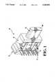
- FIG. 1illustrates a fully assembled duplex embodiment of the fiber optic receptacle assembly 10 according to the present invention.
- FIG. 2is an exploded perspective drawing showing the manner of assembly of the discrete parts of FIG. 1.
- FIG. 3is a perspective view of a standard receptacle cover as may be used in conjunction with the receptacle of the present invention.
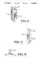
- FIG. 4is a bottom view of the main receptacle section 30 of FIGS. 1 and 2.
- FIG. 5is a cross-section of the main receptacle section 30 of FIGS. 1-2.
- FIG. 6is a perspective view of the end panel section 20 of FIGS. 1 and 2.
- FIG. 7is a bottom view of the end panel section 20 of FIG. 6.
- FIG. 8is a side view of the end panel section 20 of FIGS. 6 and 7.
- FIG. 9illustrates a cut-away perspective view of the fully assembled duplex embodiment of FIG. 1.
- FIG. 1shows a fully assembled embodiment of the fiber optic receptacle assembly 10 according to the present invention
- FIG. 2is an exploded perspective drawing showing the manner of assembly of the several parts.
- the partsinclude a receptacle housing which is formed from discrete interlocking sections 20 and 30.
- the receptacle assembly 10further includes one or more conductive shields 40 each of which is provided with a number of downwardly extending conductive terminals 41.
- the shields (a.k.a. "cans") 40are stamped from metal and are configured to form an open ended enclosure for reducing electromagnetic interference. Shields 40 have downwardly protruding conductive terminals 41 which may be soldered to corresponding tracks on a printed circuit board.
- the upper portion of each conductive shield 40is formed as an enclosure for receiving a corresponding active optical device 50. Tabs are provided at the bottom end of the enclosure to limit insertion of active optical devices 50 therein.
- Optical devices 50may be conventional photo-diodes, photo-transistors, or photo-sensitive integrated circuits.
- the device 50 shown in FIG. 2is a photographic integrated circuit having a plurality of downwardly extending terminals 51.
- Interlocking sections 20 and 30come together to form a fitted chamber in which the shields 40 and optical devices 50 may be seated.
- Dust cover 60includes a shroud 62 for insertion within the open end of the main section 30 of the receptacle housing.
- Shroud 62conforms to the opening in section 30 and provides a resistance fit therein.
- Receptacle cover 60also includes a stopper 64 (or flange) encircling the shroud for limiting insertion within the receptacle section 30. Stopper 64 also seals the open end of the receptacle assembly 10 when the receptacle cover 60 is fully inserted.
- Receptacle cover 60also includes an outwardly extending tab 66 to facilitate handling of the receptacle assembly 10.
- the main section 30 of the receptacle housinggenerally comprises a walled structure which defines a central chamber 31.
- Main section 30is open at a first end 32 to receive a receptacle cover 60 or, alternatively, a mating fiber optic plug (not shown) and the second or opposed end for receiving optical devices 50.
- the illustrated duplex embodiment of main section 30is flared at end 34 to accommodate two side-by-side active optical devices 50 with accompanying shields 40. Active optical devices 50 are slidably inserted into the shields 40 with terminals 51 of optical devices 50 extending parallely downward alongside terminals 41 of shields 40.
- the main section 30 of the receptacle housingis also configured with a stepped outer lip 36 encircling the central chamber 31.
- Outer lip 36cooperates with a complementary surface on cover 20 to prevent light from entering the cavity, as illustrated in FIG. 6.
- Shields 40 and active optical devices 50may be inserted into the open end 34 of main section 30 until they become seated against respective stop surfaces within the housing.
- a plurality of channels 38extend along the bottom of main section 30 from the open end 34 to the desired stop surface. These channels 38 accommodate conductive terminals 41 extending downwardly from the respective shields 40, as seen in FIG. 9.
- Channels 38open into a perpendicular slot 39 that is defined when the two sections 20, 30 of the housing are assembled. Slot 39 accommodates the conductive terminals 51 of active optical devices 50 in the completed assembly 10.
- the main section 30may be provided with an integrally molded alignment and ferrule-receiving member(s) 37 supported within the central chamber of the receptacle housing.
- Ferrule-receiving members 37include a bore or channel 35 to provide an optical communication path between the active optical devices 50 and the open end 32 of housing main section 30.
- ferrule-receiving members 37cooperate with a commercially available type of optical device 50 which is formed with a concave face to facilitate alignment.
- the ferrule-receiving members 37 of the main housing section 30make use of the concave face to perform a self-alignment feature as will be described.
- Ferrule-receiving members 37are provided with frusto-conical tips which are designed to cooperate with a concave face of optical devices 50 to facilitate self-alignment.
- receptacle section 20generally comprises a rectangular end panel having a series of integrally molded resilient first pegs 22 extending therefrom.
- Pegs 22are arranged to fit within the channels 38 of main section 30 of the receptacle housing.
- Pegs 22are dimensioned to provide a secure resistance fit in and along each of channels 38. The depth to which the pegs 22 can be inserted into the respective channels is adjustable to accommodate the range of tolerances for the devices 50 and shields 40.
- Section 20 of the receptacle housingmay also be provided with additional second pins 24 to increase the stability of the resistance fit and to properly align section 20 during insertion in main section 30. As can be seen in FIGS.
- the inner surface of cover 20preferably includes a plurality of third pins or dimples 26 that are configured to extend through cooperation apertures in the shield and press against the rear surface of the optical devices 50, thereby ensuring that the devices are held in alignment against the frusto-conical tips of ferrule-receiving members 37.
- shields 40 with active optical devices 50are fully inserted within main section 30 of the receptacle housing until they are seated against cooperating stop surfaces therein. End panel or cover section 20 of the receptacle housing is then inserted within main section 30 to fully enclose shields 40 and active optical devices 50.
- pegs 22urge the shields 40 and optical devices 50 fully backward against the respective stop surfaces of main section 30. Pegs 22 enter channels 38 of main section 30 and become anchored therein to provide a secure resistance fit. Pegs 26 push against the optical devices 50 to assure the devices are aligned against the associated ferrule-receiving member.
- FIG. 9is a perspective cut-away view showing the fully assembled receptacle assembly.
- housing section 20When housing section 20 is fully inserted within housing main section 30 such that optical devices 50 are sealed within, the optical devices 50 are held in exact alignment with ferrule-receiving member by the pegs 26 and are tightly anchored within the central chamber of housing main section 30.
- the compressive fit of the frusto-conical tip of interior ferrule 37 against the concave face of active optical devices 50secures the aligned optical devices 50 and sustains the alignment despite the frequently punishing assembly process.
- receptacle cover 60is eventually removed and replaced by a conventional fiber optic plug, the optical fibers terminating in the plug will be perfectly aligned with the active optical devices 50 within the receptacle assembly 10 of the present invention.
- the alignment features of the ferrule-receiving members 37may be eliminated and a receptacle cover having extending alignment pylon(s) as shown and described in co-pending application Ser. No. 905,937 may be used to achieve the same purpose.
- the completed receptacle assembly 10may be easily attached to a circuit board (not shown) and anchored thereto by pylons 33 that extend from the bottom of main housing 30, as shown in FIG. 9. Terminals 41 and 51 may conveniently be soldered to the respective tracks of the printed circuit board.
- the secure resistance fit provided by the interlocking pegs 22 of cover panel section 20 within the channel 38 of main housing section 30maintains the integrity of the completed receptacle assembly 10 throughout the assembly process, and exact alignment is maintained.
Landscapes
- Physics & Mathematics (AREA)
- General Physics & Mathematics (AREA)
- Optics & Photonics (AREA)
- Electromagnetism (AREA)
- Optical Couplings Of Light Guides (AREA)
Abstract
Description
Claims (20)
Priority Applications (1)
| Application Number | Priority Date | Filing Date | Title |
|---|---|---|---|
| US07/906,103US5259053A (en) | 1992-06-29 | 1992-06-29 | Discrete optical receptacle assembly with alignment feature |
Applications Claiming Priority (1)
| Application Number | Priority Date | Filing Date | Title |
|---|---|---|---|
| US07/906,103US5259053A (en) | 1992-06-29 | 1992-06-29 | Discrete optical receptacle assembly with alignment feature |
Publications (1)
| Publication Number | Publication Date |
|---|---|
| US5259053Atrue US5259053A (en) | 1993-11-02 |
Family
ID=25421941
Family Applications (1)
| Application Number | Title | Priority Date | Filing Date |
|---|---|---|---|
| US07/906,103Expired - Fee RelatedUS5259053A (en) | 1992-06-29 | 1992-06-29 | Discrete optical receptacle assembly with alignment feature |
Country Status (1)
| Country | Link |
|---|---|
| US (1) | US5259053A (en) |
Cited By (31)
| Publication number | Priority date | Publication date | Assignee | Title |
|---|---|---|---|---|
| US5598497A (en)* | 1995-07-14 | 1997-01-28 | Cogent Light Technologies, Inc. | Apparatus for mounting a light source within a system for coupling light into an optic fiber or fiber bundle |
| WO1997045759A1 (en)* | 1996-05-24 | 1997-12-04 | Siemens Aktiengesellschaft | Electro-optical module |
| USD389123S (en) | 1996-04-08 | 1998-01-13 | Panduit Corp. | Fiber optic transceiver module |
| USD389802S (en) | 1996-04-08 | 1998-01-27 | Panduit Corp | Fiber optic transceiver module |
| US5812717A (en)* | 1996-01-18 | 1998-09-22 | Methode Electronics, Inc. | Optical package with alignment means and method of assembling an optical package |
| US5933558A (en)* | 1997-05-22 | 1999-08-03 | Motorola, Inc. | Optoelectronic device and method of assembly |
| US6014476A (en)* | 1996-05-24 | 2000-01-11 | Siemens Aktiengesellschaft | Electro-optical module |
| USD434376S (en) | 2000-02-07 | 2000-11-28 | Panduit Corp. | Fiber optic plug connector |
| US6447171B1 (en) | 2000-02-04 | 2002-09-10 | Fci Americas Technology, Inc | Multi-fiber array connector system |
| US6450703B1 (en) | 1999-06-30 | 2002-09-17 | Yazaki Corporation | Receptacle of optical connector |
| US20020141706A1 (en)* | 2001-04-03 | 2002-10-03 | Autonetworks Technologies, Ltd | Optical connector, optical element holding structure, and structure of a mount section of an optical connector |
| US20020150351A1 (en)* | 2001-04-03 | 2002-10-17 | Autonetworks Technologies, Ltd. | Optical connector |
| USD475980S1 (en) | 2001-10-17 | 2003-06-17 | Hon Hai Precision Ind. Co., Ltd. | Optical switch |
| US20030113120A1 (en)* | 2001-11-30 | 2003-06-19 | Nobuyuki Ohe | Optical transmitter-receiver module and electronic device using the same |
| US20040099429A1 (en)* | 1999-08-23 | 2004-05-27 | Norman Castellani | Quad receptacle, dual circuit flush poke-through wiring fitting with internally mountable communication/data jacks |
| EP1227349A3 (en)* | 2001-01-18 | 2004-06-23 | Autonetworks Technologies, Ltd. | Optical connector and shield connector therefor |
| WO2004031817A3 (en)* | 2002-09-30 | 2004-07-08 | Matsushita Electric Works Ltd | Optical receptacle with low transmission loss and photoelectric conversion module for the same |
| EP1248129A3 (en)* | 2001-04-06 | 2004-09-01 | Autonetworks Technologies, Ltd. | Optical connector |
| US6799902B2 (en) | 2000-12-26 | 2004-10-05 | Emcore Corporation | Optoelectronic mounting structure |
| US20040252950A1 (en)* | 2003-05-09 | 2004-12-16 | Molex Incorporated | Method for producing an assembly comprising a waveguide section and an optical component |
| US6840686B2 (en) | 1999-05-26 | 2005-01-11 | Jds Uniphase Corporation | Method and apparatus for vertical board construction of fiber optic transmitters, receivers and transceivers |
| US6863444B2 (en) | 2000-12-26 | 2005-03-08 | Emcore Corporation | Housing and mounting structure |
| US6863453B2 (en) | 2003-01-28 | 2005-03-08 | Emcore Corporation | Method and apparatus for parallel optical transceiver module assembly |
| US6867377B2 (en) | 2000-12-26 | 2005-03-15 | Emcore Corporation | Apparatus and method of using flexible printed circuit board in optical transceiver device |
| US20050069262A1 (en)* | 2003-09-26 | 2005-03-31 | Teradyne, Inc. | Protective covers for fiber optic connector to modular protective covers for fiber optic connector assembly. |
| US6901221B1 (en) | 1999-05-27 | 2005-05-31 | Jds Uniphase Corporation | Method and apparatus for improved optical elements for vertical PCB fiber optic modules |
| US6905260B2 (en) | 2000-12-26 | 2005-06-14 | Emcore Corporation | Method and apparatus for coupling optical elements to optoelectronic devices for manufacturing optical transceiver modules |
| US7021836B2 (en) | 2000-12-26 | 2006-04-04 | Emcore Corporation | Attenuator and conditioner |
| US20060093281A1 (en)* | 2004-10-28 | 2006-05-04 | Kesler James R | Fiber optic connector |
| EP0928980B1 (en)* | 1998-01-13 | 2007-05-30 | Yazaki Corporation | Cap for optical connector |
| US20230280552A1 (en)* | 2020-09-09 | 2023-09-07 | HARTING Electronics GmbH | Optoelectronic module, optoelectronic plug connector and optoelectronic sub-distribution unit |
Citations (16)
| Publication number | Priority date | Publication date | Assignee | Title |
|---|---|---|---|---|
| US4533209A (en)* | 1983-10-24 | 1985-08-06 | Motorola, Inc. | Connectorless fiber optic package |
| US4767179A (en)* | 1982-12-20 | 1988-08-30 | Molex Incorporated | Fiber optic connector assembly |
| US4778240A (en)* | 1987-02-12 | 1988-10-18 | Hosiden Electronics Co., Ltd. | Pin jack with an optical element holder |
| US4993803A (en)* | 1989-05-18 | 1991-02-19 | General Motors Corporation | Electro-optical header connector |
| US5005939A (en)* | 1990-03-26 | 1991-04-09 | International Business Machines Corporation | Optoelectronic assembly |
| US5071219A (en)* | 1990-11-09 | 1991-12-10 | General Motors Corporation | Fiber optic connection system and method |
| US5073046A (en)* | 1991-03-11 | 1991-12-17 | Amp Incorporated | Connector with floating alignment feature |
| US5078515A (en)* | 1990-12-05 | 1992-01-07 | Wang Laboratories, Inc. | Optical fiber connector apparatus and method |
| US5091991A (en)* | 1991-02-25 | 1992-02-25 | Amp Incorporated | Optical fiber connector with alignment feature |
| US5104243A (en)* | 1990-04-23 | 1992-04-14 | E. I. Du Pont De Nemours And Company | Device for electro-optical signal conversion |
| US5117476A (en)* | 1990-01-19 | 1992-05-26 | Amp Incorporated | Optical transceiver package with insertable subassembly |
| US5125056A (en)* | 1986-05-14 | 1992-06-23 | Mcdonnell Douglas Corporation | Fiber optic connector assembly |
| US5127073A (en)* | 1990-06-21 | 1992-06-30 | Amp Incorporated | Active device mount with push-pull optical fiber connector receptacle |
| US5138680A (en)* | 1991-04-17 | 1992-08-11 | Amp Incorporated | Optical fiber connector with elastomeric centering and floating alignment feature |
| US5138679A (en)* | 1991-04-17 | 1992-08-11 | Amp Incorporated | Optical fiber connector with centering and floating alignment feature |
| US5140663A (en)* | 1991-04-17 | 1992-08-18 | Amp Incorporated | Latching beam mechanism having plug stops for optical connector |
- 1992
- 1992-06-29USUS07/906,103patent/US5259053A/ennot_activeExpired - Fee Related
Patent Citations (16)
| Publication number | Priority date | Publication date | Assignee | Title |
|---|---|---|---|---|
| US4767179A (en)* | 1982-12-20 | 1988-08-30 | Molex Incorporated | Fiber optic connector assembly |
| US4533209A (en)* | 1983-10-24 | 1985-08-06 | Motorola, Inc. | Connectorless fiber optic package |
| US5125056A (en)* | 1986-05-14 | 1992-06-23 | Mcdonnell Douglas Corporation | Fiber optic connector assembly |
| US4778240A (en)* | 1987-02-12 | 1988-10-18 | Hosiden Electronics Co., Ltd. | Pin jack with an optical element holder |
| US4993803A (en)* | 1989-05-18 | 1991-02-19 | General Motors Corporation | Electro-optical header connector |
| US5117476A (en)* | 1990-01-19 | 1992-05-26 | Amp Incorporated | Optical transceiver package with insertable subassembly |
| US5005939A (en)* | 1990-03-26 | 1991-04-09 | International Business Machines Corporation | Optoelectronic assembly |
| US5104243A (en)* | 1990-04-23 | 1992-04-14 | E. I. Du Pont De Nemours And Company | Device for electro-optical signal conversion |
| US5127073A (en)* | 1990-06-21 | 1992-06-30 | Amp Incorporated | Active device mount with push-pull optical fiber connector receptacle |
| US5071219A (en)* | 1990-11-09 | 1991-12-10 | General Motors Corporation | Fiber optic connection system and method |
| US5078515A (en)* | 1990-12-05 | 1992-01-07 | Wang Laboratories, Inc. | Optical fiber connector apparatus and method |
| US5091991A (en)* | 1991-02-25 | 1992-02-25 | Amp Incorporated | Optical fiber connector with alignment feature |
| US5073046A (en)* | 1991-03-11 | 1991-12-17 | Amp Incorporated | Connector with floating alignment feature |
| US5138680A (en)* | 1991-04-17 | 1992-08-11 | Amp Incorporated | Optical fiber connector with elastomeric centering and floating alignment feature |
| US5138679A (en)* | 1991-04-17 | 1992-08-11 | Amp Incorporated | Optical fiber connector with centering and floating alignment feature |
| US5140663A (en)* | 1991-04-17 | 1992-08-18 | Amp Incorporated | Latching beam mechanism having plug stops for optical connector |
Cited By (48)
| Publication number | Priority date | Publication date | Assignee | Title |
|---|---|---|---|---|
| US5598497A (en)* | 1995-07-14 | 1997-01-28 | Cogent Light Technologies, Inc. | Apparatus for mounting a light source within a system for coupling light into an optic fiber or fiber bundle |
| US5812717A (en)* | 1996-01-18 | 1998-09-22 | Methode Electronics, Inc. | Optical package with alignment means and method of assembling an optical package |
| USD389123S (en) | 1996-04-08 | 1998-01-13 | Panduit Corp. | Fiber optic transceiver module |
| USD389802S (en) | 1996-04-08 | 1998-01-27 | Panduit Corp | Fiber optic transceiver module |
| USRE44892E1 (en) | 1996-05-24 | 2014-05-13 | Finisar Corporation | Electro-optical module |
| WO1997045759A1 (en)* | 1996-05-24 | 1997-12-04 | Siemens Aktiengesellschaft | Electro-optical module |
| US6014476A (en)* | 1996-05-24 | 2000-01-11 | Siemens Aktiengesellschaft | Electro-optical module |
| US5933558A (en)* | 1997-05-22 | 1999-08-03 | Motorola, Inc. | Optoelectronic device and method of assembly |
| EP0928980B1 (en)* | 1998-01-13 | 2007-05-30 | Yazaki Corporation | Cap for optical connector |
| US6840686B2 (en) | 1999-05-26 | 2005-01-11 | Jds Uniphase Corporation | Method and apparatus for vertical board construction of fiber optic transmitters, receivers and transceivers |
| US6901221B1 (en) | 1999-05-27 | 2005-05-31 | Jds Uniphase Corporation | Method and apparatus for improved optical elements for vertical PCB fiber optic modules |
| DE19963426C2 (en)* | 1999-06-30 | 2002-09-26 | Yazaki Corp | Socket of an optical connector |
| US6450703B1 (en) | 1999-06-30 | 2002-09-17 | Yazaki Corporation | Receptacle of optical connector |
| US20040099429A1 (en)* | 1999-08-23 | 2004-05-27 | Norman Castellani | Quad receptacle, dual circuit flush poke-through wiring fitting with internally mountable communication/data jacks |
| US6447171B1 (en) | 2000-02-04 | 2002-09-10 | Fci Americas Technology, Inc | Multi-fiber array connector system |
| USD434376S (en) | 2000-02-07 | 2000-11-28 | Panduit Corp. | Fiber optic plug connector |
| US6799902B2 (en) | 2000-12-26 | 2004-10-05 | Emcore Corporation | Optoelectronic mounting structure |
| US7021836B2 (en) | 2000-12-26 | 2006-04-04 | Emcore Corporation | Attenuator and conditioner |
| US6905260B2 (en) | 2000-12-26 | 2005-06-14 | Emcore Corporation | Method and apparatus for coupling optical elements to optoelectronic devices for manufacturing optical transceiver modules |
| US6867377B2 (en) | 2000-12-26 | 2005-03-15 | Emcore Corporation | Apparatus and method of using flexible printed circuit board in optical transceiver device |
| US6863444B2 (en) | 2000-12-26 | 2005-03-08 | Emcore Corporation | Housing and mounting structure |
| EP1227349A3 (en)* | 2001-01-18 | 2004-06-23 | Autonetworks Technologies, Ltd. | Optical connector and shield connector therefor |
| US20020150351A1 (en)* | 2001-04-03 | 2002-10-17 | Autonetworks Technologies, Ltd. | Optical connector |
| US20040071412A1 (en)* | 2001-04-03 | 2004-04-15 | Autonetworks Technologies, Ltd. | Optical connector, optical element holding structure, and structure of a mount section of an optical connector |
| US20020141706A1 (en)* | 2001-04-03 | 2002-10-03 | Autonetworks Technologies, Ltd | Optical connector, optical element holding structure, and structure of a mount section of an optical connector |
| US6939054B2 (en) | 2001-04-03 | 2005-09-06 | Autonetworks Technologies, Ltd. | Holding structures for optical elements of an optical connector |
| US6796726B2 (en) | 2001-04-03 | 2004-09-28 | Sumitomo Wiring Systems, Ltd. | Optical connector |
| US20040071406A1 (en)* | 2001-04-03 | 2004-04-15 | Autonetworks Technologies, Ltd. | Optical connector, optical element holding structure, and structure of a mount section of an optical connector |
| US6860643B2 (en) | 2001-04-03 | 2005-03-01 | Autonetworks Technologies, Limited | Optical connector with a surface mounted shield |
| EP1248128A3 (en)* | 2001-04-03 | 2004-06-02 | Autonetworks Technologies, Ltd. | Optical connector, optical element holding structure, and structure of a mount section of an optical connector |
| EP1524538A1 (en)* | 2001-04-03 | 2005-04-20 | Autonetworks Technologies, Ltd. | Optical connector, optical element holding structure, and structure of a mount section of an optical connector |
| EP1248127A3 (en)* | 2001-04-03 | 2004-06-02 | Autonetworks Technologies, Ltd. | Optical connector |
| US6817775B2 (en) | 2001-04-06 | 2004-11-16 | Sumitomo Wiring Systems, Ltd. | Optical connector with electromagnetic noise shielding and heat radiating properties |
| EP1248129A3 (en)* | 2001-04-06 | 2004-09-01 | Autonetworks Technologies, Ltd. | Optical connector |
| USD475980S1 (en) | 2001-10-17 | 2003-06-17 | Hon Hai Precision Ind. Co., Ltd. | Optical switch |
| DE10255625B4 (en)* | 2001-11-30 | 2006-03-16 | Sharp K.K. | Optical transceiver module and electronic device using the module |
| US20030113120A1 (en)* | 2001-11-30 | 2003-06-19 | Nobuyuki Ohe | Optical transmitter-receiver module and electronic device using the same |
| US7090410B2 (en) | 2002-09-30 | 2006-08-15 | Matsushita Electric Works, Ltd. | Optical receptacle with low transmission loss and photoelectric conversion module for the same |
| WO2004031817A3 (en)* | 2002-09-30 | 2004-07-08 | Matsushita Electric Works Ltd | Optical receptacle with low transmission loss and photoelectric conversion module for the same |
| US20060045435A1 (en)* | 2002-09-30 | 2006-03-02 | Yoshiaki Kambe | Optical receptacle with low transmission and photoelectric conversion module for the same |
| US6863453B2 (en) | 2003-01-28 | 2005-03-08 | Emcore Corporation | Method and apparatus for parallel optical transceiver module assembly |
| US20040252950A1 (en)* | 2003-05-09 | 2004-12-16 | Molex Incorporated | Method for producing an assembly comprising a waveguide section and an optical component |
| US20050069262A1 (en)* | 2003-09-26 | 2005-03-31 | Teradyne, Inc. | Protective covers for fiber optic connector to modular protective covers for fiber optic connector assembly. |
| US6986607B2 (en) | 2003-09-26 | 2006-01-17 | Roth Richard F | Protective covers for fiber optic connector to modular protective covers for fiber optic connector assembly |
| US7128475B2 (en)* | 2004-10-28 | 2006-10-31 | Schweitzer Engineering Laboratories, Inc. | Fiber optic connector |
| US20060093281A1 (en)* | 2004-10-28 | 2006-05-04 | Kesler James R | Fiber optic connector |
| US20230280552A1 (en)* | 2020-09-09 | 2023-09-07 | HARTING Electronics GmbH | Optoelectronic module, optoelectronic plug connector and optoelectronic sub-distribution unit |
| US12242120B2 (en)* | 2020-09-09 | 2025-03-04 | HARTING Electronics GmbH | Optoelectronic module, optoelectronic plug connector and optoelectronic sub-distribution unit |
Similar Documents
| Publication | Publication Date | Title |
|---|---|---|
| US5259053A (en) | Discrete optical receptacle assembly with alignment feature | |
| US5734558A (en) | Removable optoelectronic module | |
| US4944568A (en) | Fiber optic connector assembly | |
| US5546281A (en) | Removable optoelectronic transceiver module with potting box | |
| US5864468A (en) | Removable optoelectronic module with grounding means | |
| EP0117022B1 (en) | Fiber optic connector assembly | |
| US5717533A (en) | Removable optoelectronic module | |
| EP0442608B1 (en) | Transceiver package | |
| US6220878B1 (en) | Optoelectronic module with grounding means | |
| US6039606A (en) | Cable connector | |
| US6485192B1 (en) | Optical device having an integral array interface | |
| US5202943A (en) | Optoelectronic assembly with alignment member | |
| US4969924A (en) | Electro-optical connector plug | |
| US6431887B1 (en) | Electrical connector assembly with an EMI shielded plug and grounding latch member | |
| US5395250A (en) | Low profile board to board connector | |
| US5619604A (en) | Multi-fiber optical connector | |
| US6980437B2 (en) | Pluggable electronic receptacle with heat sink assembly | |
| US6485322B1 (en) | Removable latch and bezel EMI grounding feature for fiber-optic transceivers | |
| EP0468671B1 (en) | Fiber optic interconnect for wall outlet | |
| JPH08265180A (en) | Transceiver module and receptacle assembly | |
| US20040043659A1 (en) | Electrical connector having improved shielding member and method of making the same | |
| US4479696A (en) | Housing for interfacing a semiconductor device with a fiber optic cable | |
| JPS6182691A (en) | Jack for modular plug connector | |
| GB2079966A (en) | Housing for Interfacing a Semiconductor Device With a Fiber Optic Cable | |
| US5883787A (en) | Floating guided connector and method |
Legal Events
| Date | Code | Title | Description |
|---|---|---|---|
| AS | Assignment | Owner name:AMP INCORPORATED, PENNSYLVANIA Free format text:ASSIGNMENT OF ASSIGNORS INTEREST.;ASSIGNORS:SCHAFFER, RONALD R.;WARNER, GARY N.;REEL/FRAME:006204/0959;SIGNING DATES FROM 19920628 TO 19920629 | |
| AS | Assignment | Owner name:WHITAKER CORPORATION, THE, DELAWARE Free format text:ASSIGNMENT OF ASSIGNORS INTEREST;ASSIGNOR:AMP INVESTMENTS;REEL/FRAME:006635/0082 Effective date:19920812 Owner name:AMP INVESTMENTS, DELAWARE Free format text:ASSIGNMENT OF ASSIGNORS INTEREST;ASSIGNOR:AMP INCORPORATED;REEL/FRAME:006635/0085 Effective date:19920812 | |
| FPAY | Fee payment | Year of fee payment:4 | |
| REMI | Maintenance fee reminder mailed | ||
| LAPS | Lapse for failure to pay maintenance fees | ||
| LAPS | Lapse for failure to pay maintenance fees | Free format text:PATENT EXPIRED FOR FAILURE TO PAY MAINTENANCE FEES (ORIGINAL EVENT CODE: EXP.); ENTITY STATUS OF PATENT OWNER: LARGE ENTITY | |
| STCH | Information on status: patent discontinuation | Free format text:PATENT EXPIRED DUE TO NONPAYMENT OF MAINTENANCE FEES UNDER 37 CFR 1.362 | |
| FP | Lapsed due to failure to pay maintenance fee | Effective date:20011102 |