US5258122A - Cross-flow filter device with pressure-balancing feature - Google Patents
Cross-flow filter device with pressure-balancing featureDownload PDFInfo
- Publication number
- US5258122A US5258122AUS07/869,997US86999792AUS5258122AUS 5258122 AUS5258122 AUS 5258122AUS 86999792 AUS86999792 AUS 86999792AUS 5258122 AUS5258122 AUS 5258122A
- Authority
- US
- United States
- Prior art keywords
- filter
- fluid
- drainage
- channel
- distribution
- Prior art date
- Legal status (The legal status is an assumption and is not a legal conclusion. Google has not performed a legal analysis and makes no representation as to the accuracy of the status listed.)
- Expired - Fee Related
Links
- 239000012530fluidSubstances0.000claimsabstractdescription84
- 238000000034methodMethods0.000claimsabstractdescription17
- 238000009295crossflow filtrationMethods0.000claimsabstractdescription12
- 239000012528membraneSubstances0.000claimsdescription57
- 238000009826distributionMethods0.000claimsdescription33
- 239000000463materialSubstances0.000claimsdescription22
- 239000012466permeateSubstances0.000claimsdescription20
- 239000012465retentateSubstances0.000claimsdescription12
- 229920002492poly(sulfone)Polymers0.000claimsdescription7
- NLHHRLWOUZZQLW-UHFFFAOYSA-NAcrylonitrileChemical compoundC=CC#NNLHHRLWOUZZQLW-UHFFFAOYSA-N0.000claimsdescription5
- BZHJMEDXRYGGRV-UHFFFAOYSA-NVinyl chlorideChemical compoundClC=CBZHJMEDXRYGGRV-UHFFFAOYSA-N0.000claimsdescription5
- 229920001577copolymerPolymers0.000claimsdescription5
- 229920003023plasticPolymers0.000claimsdescription5
- 239000012209synthetic fiberSubstances0.000claimsdescription5
- 229920002994synthetic fiberPolymers0.000claimsdescription5
- 230000005465channelingEffects0.000claimsdescription3
- 239000012141concentrateSubstances0.000claimsdescription3
- 238000000926separation methodMethods0.000claims1
- 238000001914filtrationMethods0.000abstractdescription22
- 230000010349pulsationEffects0.000abstractdescription6
- 230000004044responseEffects0.000abstractdescription4
- 239000007788liquidSubstances0.000description6
- 238000001471micro-filtrationMethods0.000description6
- 238000000108ultra-filtrationMethods0.000description6
- 230000008569processEffects0.000description4
- 230000008901benefitEffects0.000description3
- 230000000295complement effectEffects0.000description3
- 238000004519manufacturing processMethods0.000description3
- 229910000619316 stainless steelInorganic materials0.000description2
- 230000004888barrier functionEffects0.000description2
- 230000000694effectsEffects0.000description2
- 230000004048modificationEffects0.000description2
- 238000012986modificationMethods0.000description2
- 230000002572peristaltic effectEffects0.000description2
- 229920002466DynelPolymers0.000description1
- 238000004026adhesive bondingMethods0.000description1
- 238000012993chemical processingMethods0.000description1
- 238000004140cleaningMethods0.000description1
- 238000010276constructionMethods0.000description1
- 230000008602contractionEffects0.000description1
- 238000011118depth filtrationMethods0.000description1
- 238000013461designMethods0.000description1
- 238000011161developmentMethods0.000description1
- 230000004907fluxEffects0.000description1
- 238000002844meltingMethods0.000description1
- 238000011017operating methodMethods0.000description1
- 230000010287polarizationEffects0.000description1
- 239000011148porous materialSubstances0.000description1
- 238000012545processingMethods0.000description1
- 238000012958reprocessingMethods0.000description1
- 238000007873sievingMethods0.000description1
- 230000002459sustained effectEffects0.000description1
- 238000011144upstream manufacturingMethods0.000description1
- 238000003466weldingMethods0.000description1
Images


Classifications
- B—PERFORMING OPERATIONS; TRANSPORTING
- B01—PHYSICAL OR CHEMICAL PROCESSES OR APPARATUS IN GENERAL
- B01D—SEPARATION
- B01D65/00—Accessories or auxiliary operations, in general, for separation processes or apparatus using semi-permeable membranes
- B01D65/08—Prevention of membrane fouling or of concentration polarisation
- B—PERFORMING OPERATIONS; TRANSPORTING
- B01—PHYSICAL OR CHEMICAL PROCESSES OR APPARATUS IN GENERAL
- B01D—SEPARATION
- B01D61/00—Processes of separation using semi-permeable membranes, e.g. dialysis, osmosis or ultrafiltration; Apparatus, accessories or auxiliary operations specially adapted therefor
- B01D61/14—Ultrafiltration; Microfiltration
- B01D61/18—Apparatus therefor
- B—PERFORMING OPERATIONS; TRANSPORTING
- B01—PHYSICAL OR CHEMICAL PROCESSES OR APPARATUS IN GENERAL
- B01D—SEPARATION
- B01D61/00—Processes of separation using semi-permeable membranes, e.g. dialysis, osmosis or ultrafiltration; Apparatus, accessories or auxiliary operations specially adapted therefor
- B01D61/14—Ultrafiltration; Microfiltration
- B01D61/20—Accessories; Auxiliary operations
- B—PERFORMING OPERATIONS; TRANSPORTING
- B01—PHYSICAL OR CHEMICAL PROCESSES OR APPARATUS IN GENERAL
- B01D—SEPARATION
- B01D63/00—Apparatus in general for separation processes using semi-permeable membranes
- B01D63/08—Flat membrane modules
- B01D63/082—Flat membrane modules comprising a stack of flat membranes
- B—PERFORMING OPERATIONS; TRANSPORTING
- B01—PHYSICAL OR CHEMICAL PROCESSES OR APPARATUS IN GENERAL
- B01D—SEPARATION
- B01D2321/00—Details relating to membrane cleaning, regeneration, sterilization or to the prevention of fouling
- B01D2321/20—By influencing the flow
- B01D2321/2066—Pulsated flow
Definitions
- the present inventionrelates to cross-flow filtration and more particularly towards disposable, compact cross-flow filters and filtration methods incorporating a novel pressure-balancing arrangement.
- Ultrafiltration and microfiltrationare chemical processing operations that are useful as practical operating methods for a large number of applications.
- the single most important step in achieving sustained practical filtration rateswas the development of a family of anisotropic polymeric ultrafiltration and microfiltration membranes of various molecular weight cutoffs (MWCO) having effective pore sizes of from about 10 ⁇ to the micron range.
- MWCOmolecular weight cutoffs
- These membranesexhibit very high flow rates at normal operating pressures, and good resistance to plugging. The latter phenomenon is believed to be largely assignable to a very thin barrier layer on the upstream side of the membrane which allows the membrane to perform as a surface-type rather than a depth-type filter.
- Such ultrafiltration and microfiltration membranes as described hereinare commercially available under the trademark DIAFLO® from W. R. Grace & Co.-Conn.
- cross-flow filtrationIn order to maintain a continuous flow of liquid at the desired high flow rates using these membranes, a widely accepted technique called “cross-flow” (or tangential-flow) filtration may be used in order to process a large volume of liquid in a short time.
- cross-flow filtrationis useful with microfiltration as well as ultrafiltration membranes, the word “filtration” will be used hereinafter to refer to both “microfiltration” and “ultrafiltration”.
- filtrationi.e., cells wherein the solution in the cell to be filtered is constantly stirred by an agitating device riding just above the membrane surface at the bottom of the cell, in cross-flow filtration fluid flows across, or tangential to, the filtration membrane surface.
- a typical apparatus for carrying out cross-flow filtrationis described in U.S. Pat. No. 3,556,302, the disclosure of which is herein incorporated by reference.
- Such a devicecomprises two deflection resistant plates and a flow-distributing means between said plates which flow-distributing means is maintained in intimate contact with the face of a filter by a hydraulic pressure difference maintained across the distributor plate.
- Such pressuresare usually on the order of from about 30 psi.
- the hydraulic pressure differenceensures that the fluid flow channel formed by contact of the flow-distributing means and the membrane surface is not short-circuited.
- a peristaltic pumpis commonly used to deliver fluid to the unit; these pumps do not provide pulse-free fluid delivery.
- the fluidenters the device and the fluid pulses are absorbed by the deflection-resistant plates; however, this means that the more compliant distributor plate must "give", and it presses down on the compliant membrane with each pulsation of the fluid stream. This causes the membrane to physically "wear” faster than desired. Although some membrane materials may withstand this abuse, others cannot.
- the flow rate of the pumpmay be reduced to avoid the above problems, but at the expense of dimished throughput.
- the present inventionrelates to a device for concentrating a fluid, comprising: 1) at least one drainage means for channeling away permeate, said drainage means being disposed on a surface of a planar object, and having superimposed over each said drainage means a concentrator unit comprising: a) filter means for separating a fluid into permeate and retentate components, said filter means superimposed over said drainage means; b) distribution plate means, superimposed over said filter means, for guiding said fluid tangentially over said filter means through a channel means defined by an elongated ridge formed of said distribution means and wherein said ridge is substantially in contact with the major surface of said filter means; and c) pressure-balancing chamber means superimposed over said distribution means and communicating with said channel means via a port formed in said distribution means wherein a pressure P o is created by introducing fluid into said pressure-balancing chamber means through a second port means communicating with said pressure-balancing chamber means, said chamber means further comprising a flexible wall means.
- the inventionfurther relates to methods of fluid concentration employing such a device to a fluid concentration system, and to methods of making such a filtration device.
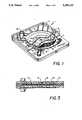
- FIG. 1depicts in perspective view a device constructed in accordance with the invention
- FIG. 2depicts the same device, in exploded view, before assembly.
- FIG. 3depicts the assembled device of FIG. 2 in cross-sectional view.
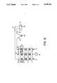
- FIG. 4depicts a filter device of the invention, in simplified side view, in operation with a system of the invention.
- FIG. 5depicts a filter device of the invention, in simplified side view configured in "recycle” mode, in operation with a system of the invention.
- FIG. 6depicts filter devices of the invention, in simplified side view advantageously joined in parallel and configured in "recycle" mode, in operation with a system of the invention.
- each such concentrator unitcomprises a plurality of intercommunicating chambers to facilitate fluid filtration, and further comprises a filter membrane superimposed over a drainage means, a distribution means for guiding fluid over the filter membrane surface to effect filtration, and a pressure-balancing chamber means superimposed over the distribution means, comprising a flexible wall. Fluid entering the pressure-balancing chamber means creates a pressure which acts on the distribution means to ensure contact between the distribution means and the filter membrane surface.
- an advantage to the inventionis that a filter device made in accordance with it is light, easy to use, leak-free, and disposable. (However, it is contemplated that such filter devices may also be large and reusable, being constructed, e g. of materials such as 316 stainless steel, and might be used e.g. in process applications.)
- a filter device of the inventionmay advantageously be made of interlocking parts made of polymeric material, which are integrally assembled to provide a unit which may be used, for example, for treating biohazardous liquids, then thrown away. This would afford the laboratory worker reduced exposure to biohazardous materials he or she would normally encounter disassembling and cleaning a conventional filter device of the current art.
- an integral unitwould eliminate having to be concerned with o-ring seals and other hardware required by filter devices of the current art requiring assembly, which could be assembled improperly by a tired lab worker and could thus leak, or not work at all.
- FIG. 1depicts a particularly advantageous embodiment of the device of the invention, wherein a filter device 1 is formed of a plurality of interlocking parts; the interlocking relationship between the parts of such a device is most easily seen in FIG. 2.
- the filter deviceis, when assembled, about 15 to 20 cm long on each side and about 3 to 5 cm thick; these dimensions are in keeping with the desire to provide a compact, disposable unit for benchtop lab work.
- FIGS. 1 and 2it is seen that a filter device 1 which comprises two concentrator units is made of a drainage plate 2, filter membranes 3 and 4, distribution plates 5 and 6, and flexible wall plates 7 and 8.
- the drainage grid 9is designed to accept a filter membrane 3 which is attached at every point along its periphery to the edge of the drainage grid 9 in a way that liquid must pass through membrane 3 to reach the drainage grid 9.
- the membrane 3may be preferably heat sealed in place, or glued or mechanically fastened by means of O-rings or gaskets.
- Suitable membraneswhich may be used, without limitation, in the invention are listed in Table 1, below, i.e., cellulosic, polysulfone, and DYNELTM (trademark for a high-melting point synthetic fiber comprising a copolymer of vinyl chloride and acrylonitrile).
- permeatepasses through the filter membrane 3 and onto the drainage grid 9, which is suitably a network of criss-crossing shallow grooves formed in said drainage plate 2 which can conduct permeate to a drainage groove 10 which carries the permeate to drainage channel 11 and a drainage opening 12 communicating with permeate port 13, from which the permeate exits the device.
- the surface of the drainage grid 9 comprising the network of criss-crossing shallow groovesshould be designed in such a way as to be deep enough to conduct fluid, but also to provide a support surface for the filter membrane 3 so it does not collapse under pressure into the groove network.
- the drainage grid 9may be easily designed by those of ordinary skill in the art, but a suitable surface pattern design which may be used is the MT-975 surface from Mold-Tech of Chicopee, Mass.
- a distribution plate 5Superimposed on the filter membrane 3 and drainage grid 9 of drainage plate 2 is a distribution plate 5.
- a recessed support surface 14On the side of the distribution plate 5 facing filter membrane 3 is a recessed support surface 14.
- a ridge 15Formed out of recessed support surface 14 is a ridge 15 which suitably begins a curvilinear path from its starting point near the center of recessed support surface 14 and proceeds outward.
- the distribution plate 5is assembled to the drainage plate 2 in such a manner as to interlock the filtration chamber wall 16 with a complementary channel 17, the ridge 15 contacts the filter membrane 3 to form a thin channel 18 through which fluid to be filtered may pass to effect cross-flow filtration by filter membrane 3. Liquid enters the thin channel 19 through port 19, passes through thin channel 18, and any retentate remaining at the end of thin channel 18 passes out retentate port 20.
- a flexible wall plate 7 having a fluid port 25interlocks with complementary shoulder 24 to form a pressure-balancing chamber 26.
- the modulus of the flexible wallis preferably less than that of the distribution plate 5, i.e., it is relatively more flexible to allow for expansion and contraction in response to fluid pressure pulsations. Fluid enters chamber 26 through fluid port 25.
- Exit port 19acts as a restriction on fluid flow from chamber 26 into thin channel 18, so as the pressure-balancing chamber 26 fills with fluid, a fluid pressure P o is generated within pressure-balancing chamber 26, which acts on flexible wall plate 7 and floor 22, and in turn, on surface 14 to keep ridge 15 substantially in contact with the surface of membrane 3.
- the large volume of chamber 26 relative to that of thin channel 18, and the small size of port 19insures that P o will always be greater than the average fluid pressure P.sub. 1 in the thin channel 18.
- P owill generally be in the range of from 2 to 30 psi and the flow rate tends to range from 50 to 1000 ml/min when the device is operated in its usual manner, i.e., when the device is configured in "recycle” mode, i.e., as in FIG. 5.
- P otends to range from 0 to 2 psi and the flow rate will generally be in the range of 0.5 to 20 ml/min.
- An additional concentrator unit as described aboveis superimposed on the other side of drainage plate 2 to form a filter unit comprising two concentrator units, depicted in exploded view in FIG. 2, and as assembled in FIG. 1.
- filtrationmay occur singly in either concentrator unit, or simultaneously in both concentrator units.
- the advantage in carrying out filtration in both concentrator units simultaneouslyis that any outward deflection of drainage plate 2 caused by the fluid pressures P o and P 1 generated in one concentrator unit will be offset by equivalent pressures from the concentrator unit superimposed over the other side of drainage plate 2.
- the drainage platedoes not have to be bulky or reinforced to withstand deflection, which reduces the mass of the device and its manufacturing cost.
- a system for concentrating fluids employing the dual-concentrator unit described aboveis schematically illustrated, in simplified side view, in FIGS. 4 and 5.
- the pumpdelivers fluid 30 to a filter device 1, through a conduit 31 which attaches to an fluid port 25 of filter device 1.
- Fluid port 32is plugged with plug 33 because fluid port 32 communicates with fluid port 25 to allow interconnection of multiple filter devices 1 as described below.
- the fluid entering fluid port 25enters each concentrator unit and is processed as previously described. Retentate is either collected in retentate reservoir 32 from conduit 33 connected to retentate port 20, as shown in the single pass system of FIG.
- Permeateis collected in reservoir 38 from permeate port 35.
- Permeate port 13which communicates with permeate port 35, is plugged with plug 39, and retentate port 36, which communicates with retentate port 20, is plugged with plug 37.
- the fluid 30 in the reservoir 27is enriched in the solutes that do not pass through the membrane. This is an advantageous way to concentrate fluids for further processing.
- a particular advantage to the filter device of the invention described aboveis that a number of the devices of FIG. 1 may be joined together in parallel in order to enhance the filtration process, as has been done in FIG. 6, shown as configured for the recycle mode.
- This configurationallows for more membrane surface to be utilized for filtration, and thus a larger feed volume of fluid may be processed by the system. This may easily be done by equipping the individual ports 20, 13, and 25 of each filter device 1 with connecting means 40 for interlocking said ports with complementary ports 36, 35, and 32 on adjoining filter devices 1, and fitting the units together.
- the various parts of the filter deviceare advantageously designed to interlock with each other to simplify manufacture.
- the partsshould be bonded to each other permanently, e.g. by gluing, mechanical attachments, i.e. screws or other fasteners, or by such techniques as ultrasonic welding. The latter technique would appear to be better suited to automated mass-production of the filter devices.
- the parts of the filter devicemay be constructed of any material which is chemically non-reactive with the fluids to be processed, and which is appropriate to maintain the structural integrity of the assembled device.
- Plastic or polymeric materialsare advantageous, because these are light in weight and inexpensive to fabricate parts from.
Landscapes
- Chemical & Material Sciences (AREA)
- Chemical Kinetics & Catalysis (AREA)
- Engineering & Computer Science (AREA)
- Water Supply & Treatment (AREA)
- Separation Using Semi-Permeable Membranes (AREA)
- Filtering Materials (AREA)
Abstract
Description
TABLE 1 ______________________________________ Membrane Name.sup. Membrane Type MWCO Classification ______________________________________ YCO5 Cellulosic 500 Ultrafiltration YM1 " 1000 " YM3 " 3000 " YM10 " 10000 " YM30 " 30000 " YM100 " 100000 " PM10 Polysulfone 10000 " PM30 " 30000 " XM50 DYNEL ™ 50000 " XM300 " 300000 " GLS.2 Polysulfone 0.2 mμ Microfiltration GLS.45 " 0.45 mμ " ______________________________________ .sup. W.R. Grace & Co. Conn.
Claims (20)
Priority Applications (3)
| Application Number | Priority Date | Filing Date | Title |
|---|---|---|---|
| US07/869,997US5258122A (en) | 1992-04-16 | 1992-04-16 | Cross-flow filter device with pressure-balancing feature |
| JP11118893AJP3395911B2 (en) | 1992-04-16 | 1993-04-15 | Cross-flow filter device with pressure balancing equipment |
| EP93302941AEP0566414A1 (en) | 1992-04-16 | 1993-04-15 | Cross-flow filter device with pressure-balancing feature |
Applications Claiming Priority (1)
| Application Number | Priority Date | Filing Date | Title |
|---|---|---|---|
| US07/869,997US5258122A (en) | 1992-04-16 | 1992-04-16 | Cross-flow filter device with pressure-balancing feature |
Publications (1)
| Publication Number | Publication Date |
|---|---|
| US5258122Atrue US5258122A (en) | 1993-11-02 |
Family
ID=25354581
Family Applications (1)
| Application Number | Title | Priority Date | Filing Date |
|---|---|---|---|
| US07/869,997Expired - Fee RelatedUS5258122A (en) | 1992-04-16 | 1992-04-16 | Cross-flow filter device with pressure-balancing feature |
Country Status (3)
| Country | Link |
|---|---|
| US (1) | US5258122A (en) |
| EP (1) | EP0566414A1 (en) |
| JP (1) | JP3395911B2 (en) |
Cited By (17)
| Publication number | Priority date | Publication date | Assignee | Title |
|---|---|---|---|---|
| US20060060518A1 (en)* | 2004-09-21 | 2006-03-23 | Jeremy Perreault | Disposable tangential flow filtration device holder |
| US20060266692A1 (en)* | 2005-05-25 | 2006-11-30 | Innovative Micro Technology | Microfabricated cross flow filter and method of manufacture |
| US20070241048A1 (en)* | 2006-04-14 | 2007-10-18 | Hunt Stephen G | Disposable tangential flow filtration device holder |
| US20080255027A1 (en)* | 2006-12-21 | 2008-10-16 | Wilson Moya | Purification of proteins |
| US20080257813A1 (en)* | 2007-03-26 | 2008-10-23 | Millipore Corporation | Cassette-style filtration apparatus |
| US20090181450A1 (en)* | 2006-06-27 | 2009-07-16 | Sebastien Ribault | Metod and unit for preparing a sample for the microbiological analysis of a liquid |
| US20090232737A1 (en)* | 2006-12-21 | 2009-09-17 | Wilson Moya | Purification of proteins |
| US20090277833A1 (en)* | 2008-05-06 | 2009-11-12 | Spf Innovations, Llc | Tangential flow filtration system |
| US20090311776A1 (en)* | 2008-06-11 | 2009-12-17 | Millipore Corporation | Stirred tank bioreactor |
| US20100190963A1 (en)* | 2008-12-16 | 2010-07-29 | Millipore Corporation | Stirred Tank Reactor And Method |
| US20100267933A1 (en)* | 2006-12-21 | 2010-10-21 | Moya Wilson | Purification of proteins |
| US20110127203A1 (en)* | 2009-05-29 | 2011-06-02 | Millipore Corporation | Disposable Tangential Flow Filtration Liner With Sensor Mount |
| US20110174711A1 (en)* | 2009-08-04 | 2011-07-21 | Millipore Corporation | Self Contained Disposable Tangential Flow Filtration Liner |
| US20110215051A1 (en)* | 2005-12-29 | 2011-09-08 | Spf Innovations, Llc | Method and apparatus for the filtration of biological solutions |
| US8691918B2 (en) | 2010-05-17 | 2014-04-08 | Emd Millipore Corporation | Stimulus responsive polymers for the purification of biomolecules |
| US20160271563A1 (en)* | 2013-06-25 | 2016-09-22 | Tetra Laval Holdings & Finance S.A. | Membrane filtration device having a hygienic suspension arrangement |
| US10864483B2 (en) | 2018-11-16 | 2020-12-15 | Integrated Protein Technologies, Snc. | Molecular weight filtration system and apparatus |
Families Citing this family (5)
| Publication number | Priority date | Publication date | Assignee | Title |
|---|---|---|---|---|
| FR2748953B1 (en)* | 1996-05-24 | 1998-10-02 | Millipore Sa | ELLIPSE-SHAPED FILTRATION UNIT |
| DE10305320B4 (en)* | 2003-02-10 | 2007-04-12 | Erhard Rudolf | Filter device, filter media and filtration method |
| SG146558A1 (en)* | 2007-03-26 | 2008-10-30 | Millipore Corp | Cassette-style filtration apparatus |
| US20080257814A1 (en)* | 2007-04-23 | 2008-10-23 | Millipore Corporation | Filtration Cartridge |
| CN104303401B (en) | 2012-07-18 | 2016-12-21 | 三菱电机株式会社 | rotating electrical machine |
Citations (15)
| Publication number | Priority date | Publication date | Assignee | Title |
|---|---|---|---|---|
| USRE26097E (en)* | 1965-03-03 | 1966-10-11 | Michaelsmembrane separation device | |
| US3556302A (en)* | 1969-01-06 | 1971-01-19 | Amicon Corp | Filtration apparatus having flow distributor |
| US3560377A (en)* | 1969-01-21 | 1971-02-02 | Amicon Corp | Apparatus and process for filtering fluids |
| US4031008A (en)* | 1973-12-04 | 1977-06-21 | Tokyo Shibaura Electric Co., Ltd. | Artificial kidney device |
| US4146485A (en)* | 1977-02-07 | 1979-03-27 | English Clays Lovering Pochin & Company Limited | Tube pressure filters |
| NL7713116A (en)* | 1977-11-29 | 1979-05-31 | Esmil B V Stationsstraat 48 | Ultra- or hyperfiltration unit - with membranes on both sides of open=ended porous support tubes and hollow flange for hanging pipes and removing filtrate |
| JPS5551606A (en)* | 1978-10-06 | 1980-04-15 | Takeaki Ogawa | Tire with earth connection |
| JPS6051506A (en)* | 1983-08-31 | 1985-03-23 | Akihiro Fujimura | Filter apparatus |
| US4601824A (en)* | 1981-12-24 | 1986-07-22 | Veb Chemieanlagenbaukombinat Leipzig-Grimma | Flat-membrane separating arrangement |
| US4695380A (en)* | 1985-03-06 | 1987-09-22 | Gkss Forschungszentrum Geesthacht Gmbh | Diaphragm-equipped fluid treating apparatus |
| US4789480A (en)* | 1982-06-01 | 1988-12-06 | Brueschke Hartmut | Membrane module and the use thereof for the separation of liquids according to the pervaporation process |
| US4869821A (en)* | 1988-04-28 | 1989-09-26 | W. R. Grace & Co.-Conn. | Drainage disc for membrane assembly |
| US4880537A (en)* | 1985-04-10 | 1989-11-14 | Mordeki Drori | Multiple disc type filter and disc construction useful therein |
| US4897190A (en)* | 1982-06-04 | 1990-01-30 | Klinkau Besitzges.Mbh | Membrane filter plate |
| JPH0295421A (en)* | 1988-09-30 | 1990-04-06 | Daikin Ind Ltd | liquid separator |
Family Cites Families (3)
| Publication number | Priority date | Publication date | Assignee | Title |
|---|---|---|---|---|
| DE2753864C3 (en)* | 1977-12-02 | 1981-04-16 | Carl Schleicher & Schüll GmbH & Co KG, 3352 Einbeck | Pressure filtration device |
| DE8515608U1 (en)* | 1985-05-28 | 1988-01-28 | Dr. Kohlheb Membrantechnik GmbH, 3000 Hannover | Separation cell for pressure filtration and reverse osmosis |
| DE3731864A1 (en) | 1987-09-22 | 1989-03-30 | Kohlheb Membrantechnik Gmbh Dr | Pharmaceutical module |
- 1992
- 1992-04-16USUS07/869,997patent/US5258122A/ennot_activeExpired - Fee Related
- 1993
- 1993-04-15EPEP93302941Apatent/EP0566414A1/ennot_activeCeased
- 1993-04-15JPJP11118893Apatent/JP3395911B2/ennot_activeExpired - Fee Related
Patent Citations (15)
| Publication number | Priority date | Publication date | Assignee | Title |
|---|---|---|---|---|
| USRE26097E (en)* | 1965-03-03 | 1966-10-11 | Michaelsmembrane separation device | |
| US3556302A (en)* | 1969-01-06 | 1971-01-19 | Amicon Corp | Filtration apparatus having flow distributor |
| US3560377A (en)* | 1969-01-21 | 1971-02-02 | Amicon Corp | Apparatus and process for filtering fluids |
| US4031008A (en)* | 1973-12-04 | 1977-06-21 | Tokyo Shibaura Electric Co., Ltd. | Artificial kidney device |
| US4146485A (en)* | 1977-02-07 | 1979-03-27 | English Clays Lovering Pochin & Company Limited | Tube pressure filters |
| NL7713116A (en)* | 1977-11-29 | 1979-05-31 | Esmil B V Stationsstraat 48 | Ultra- or hyperfiltration unit - with membranes on both sides of open=ended porous support tubes and hollow flange for hanging pipes and removing filtrate |
| JPS5551606A (en)* | 1978-10-06 | 1980-04-15 | Takeaki Ogawa | Tire with earth connection |
| US4601824A (en)* | 1981-12-24 | 1986-07-22 | Veb Chemieanlagenbaukombinat Leipzig-Grimma | Flat-membrane separating arrangement |
| US4789480A (en)* | 1982-06-01 | 1988-12-06 | Brueschke Hartmut | Membrane module and the use thereof for the separation of liquids according to the pervaporation process |
| US4897190A (en)* | 1982-06-04 | 1990-01-30 | Klinkau Besitzges.Mbh | Membrane filter plate |
| JPS6051506A (en)* | 1983-08-31 | 1985-03-23 | Akihiro Fujimura | Filter apparatus |
| US4695380A (en)* | 1985-03-06 | 1987-09-22 | Gkss Forschungszentrum Geesthacht Gmbh | Diaphragm-equipped fluid treating apparatus |
| US4880537A (en)* | 1985-04-10 | 1989-11-14 | Mordeki Drori | Multiple disc type filter and disc construction useful therein |
| US4869821A (en)* | 1988-04-28 | 1989-09-26 | W. R. Grace & Co.-Conn. | Drainage disc for membrane assembly |
| JPH0295421A (en)* | 1988-09-30 | 1990-04-06 | Daikin Ind Ltd | liquid separator |
Non-Patent Citations (2)
| Title |
|---|
| Filtron, "A Self-Contained Tangential Filtration Device for Laboratory/Pilot Scale Applications"; 1989; Filtron Technology Corporation. (4 pages). |
| Filtron, A Self Contained Tangential Filtration Device for Laboratory/Pilot Scale Applications ; 1989; Filtron Technology Corporation. (4 pages).* |
Cited By (42)
| Publication number | Priority date | Publication date | Assignee | Title |
|---|---|---|---|---|
| US7306727B2 (en)* | 2004-09-21 | 2007-12-11 | Millipore Corporation | Disposable tangential flow filtration device holder |
| US20060060518A1 (en)* | 2004-09-21 | 2006-03-23 | Jeremy Perreault | Disposable tangential flow filtration device holder |
| US20060266692A1 (en)* | 2005-05-25 | 2006-11-30 | Innovative Micro Technology | Microfabricated cross flow filter and method of manufacture |
| US9662614B2 (en) | 2005-12-29 | 2017-05-30 | Spf Innovations Llc | Method and apparatus for the filtration of biological solutions |
| US11633698B2 (en) | 2005-12-29 | 2023-04-25 | Spf Innovations, Llc | Method and apparatus for the filtration of biological solutions |
| US11007483B2 (en) | 2005-12-29 | 2021-05-18 | Spf Innovations, Llc | Method and apparatus for the filtration of biological solutions |
| US10421043B2 (en) | 2005-12-29 | 2019-09-24 | Spf Innovations, Llc | Method and apparatus for the filtration of biological solutions |
| US8728315B2 (en) | 2005-12-29 | 2014-05-20 | Spf Innovations, Llc | Method and apparatus for the filtration of biological solutions |
| US20110215051A1 (en)* | 2005-12-29 | 2011-09-08 | Spf Innovations, Llc | Method and apparatus for the filtration of biological solutions |
| US8157999B2 (en) | 2005-12-29 | 2012-04-17 | Spf Innovations, Llc | Method and apparatus for the filtration of biological solutions |
| US8177974B2 (en) | 2006-04-14 | 2012-05-15 | Emd Millipore Corporation | Disposable tangential flow filtration device holder |
| US9114366B2 (en) | 2006-04-14 | 2015-08-25 | Emd Millipore Corporation | Disposable tangential flow filtration device holder |
| US20070241048A1 (en)* | 2006-04-14 | 2007-10-18 | Hunt Stephen G | Disposable tangential flow filtration device holder |
| US20090181450A1 (en)* | 2006-06-27 | 2009-07-16 | Sebastien Ribault | Metod and unit for preparing a sample for the microbiological analysis of a liquid |
| US9410181B2 (en) | 2006-06-27 | 2016-08-09 | Emd Millipore Corporation | Method and unit for preparing a sample for the microbiological analysis of a liquid |
| US9090930B2 (en) | 2006-06-27 | 2015-07-28 | Emd Millipore Corporation | Method and unit for preparing a sample for the microbiological analysis of a liquid |
| US8569464B2 (en) | 2006-12-21 | 2013-10-29 | Emd Millipore Corporation | Purification of proteins |
| US10233211B2 (en) | 2006-12-21 | 2019-03-19 | Emd Millipore Corporation | Purification of proteins |
| US8362217B2 (en) | 2006-12-21 | 2013-01-29 | Emd Millipore Corporation | Purification of proteins |
| US20080255027A1 (en)* | 2006-12-21 | 2008-10-16 | Wilson Moya | Purification of proteins |
| US9376464B2 (en) | 2006-12-21 | 2016-06-28 | Emd Millipore Corporation | Purification of proteins |
| US20130317204A1 (en) | 2006-12-21 | 2013-11-28 | Emd Millipore Corporation | Purification of Proteins |
| US10793593B2 (en) | 2006-12-21 | 2020-10-06 | Emd Millipore Corporation | Purification of proteins |
| US20090232737A1 (en)* | 2006-12-21 | 2009-09-17 | Wilson Moya | Purification of proteins |
| US20100267933A1 (en)* | 2006-12-21 | 2010-10-21 | Moya Wilson | Purification of proteins |
| US20080257813A1 (en)* | 2007-03-26 | 2008-10-23 | Millipore Corporation | Cassette-style filtration apparatus |
| US8231787B2 (en) | 2008-05-06 | 2012-07-31 | Spf Innovations, Llc | Tangential flow filtration system |
| US20090277833A1 (en)* | 2008-05-06 | 2009-11-12 | Spf Innovations, Llc | Tangential flow filtration system |
| US8999702B2 (en) | 2008-06-11 | 2015-04-07 | Emd Millipore Corporation | Stirred tank bioreactor |
| US20090311776A1 (en)* | 2008-06-11 | 2009-12-17 | Millipore Corporation | Stirred tank bioreactor |
| US9803165B2 (en) | 2008-12-16 | 2017-10-31 | Emd Millipore Corporation | Stirred tank reactor and method |
| US20100190963A1 (en)* | 2008-12-16 | 2010-07-29 | Millipore Corporation | Stirred Tank Reactor And Method |
| US9289703B2 (en) | 2009-05-29 | 2016-03-22 | Emd Millipore Corporation | Disposable tangential flow filtration liner with sensor mount |
| US20110127203A1 (en)* | 2009-05-29 | 2011-06-02 | Millipore Corporation | Disposable Tangential Flow Filtration Liner With Sensor Mount |
| US8454822B2 (en) | 2009-05-29 | 2013-06-04 | Emd Millipore Corporation | Disposable tangential flow filtration liner with sensor mount |
| US20110174711A1 (en)* | 2009-08-04 | 2011-07-21 | Millipore Corporation | Self Contained Disposable Tangential Flow Filtration Liner |
| US9731288B2 (en) | 2010-05-17 | 2017-08-15 | Emd Millipore Corporation | Stimulus responsive polymers for the purification of biomolecules |
| US9217048B2 (en) | 2010-05-17 | 2015-12-22 | Emd Millipore Corporation | Stimulus responsive polymers for the purification of biomolecules |
| US8691918B2 (en) | 2010-05-17 | 2014-04-08 | Emd Millipore Corporation | Stimulus responsive polymers for the purification of biomolecules |
| US20160271563A1 (en)* | 2013-06-25 | 2016-09-22 | Tetra Laval Holdings & Finance S.A. | Membrane filtration device having a hygienic suspension arrangement |
| US9776138B2 (en)* | 2013-06-25 | 2017-10-03 | Tetra Laval Holdings & Finance S.A. | Membrane filtration device having a hygienic suspension arrangement |
| US10864483B2 (en) | 2018-11-16 | 2020-12-15 | Integrated Protein Technologies, Snc. | Molecular weight filtration system and apparatus |
Also Published As
| Publication number | Publication date |
|---|---|
| JPH0639251A (en) | 1994-02-15 |
| EP0566414A1 (en) | 1993-10-20 |
| JP3395911B2 (en) | 2003-04-14 |
Similar Documents
| Publication | Publication Date | Title |
|---|---|---|
| US5258122A (en) | Cross-flow filter device with pressure-balancing feature | |
| US3560377A (en) | Apparatus and process for filtering fluids | |
| US5104535A (en) | Frameless array of hollow fiber membranes and module containing a stack of arrays | |
| CN100435912C (en) | Disposable membrane module with low-dead volume | |
| US6312591B1 (en) | Filtration cell for tangential flow filtration and filtration system making use of such cell | |
| US20200338499A1 (en) | Permeate channel alterations for counter current filtration for use in cross-flow filtration modules useful in osmotic systems | |
| WO2007076496B1 (en) | Method and apparatus for the filtration of biological solutions | |
| US7306727B2 (en) | Disposable tangential flow filtration device holder | |
| US10183108B2 (en) | Inline diafiltration with multi-channel pump | |
| US12263449B2 (en) | Tangential flow filtration manifold | |
| US5160433A (en) | Laboratory scale ultrafiltration apparatus | |
| EP1359993B1 (en) | Hollow fiber membrane cassette | |
| US20040045890A1 (en) | Hollow fiber membrane cassette | |
| JP2004524140A5 (en) | ||
| AU2002236864A1 (en) | Hollow fiber membrane cassette | |
| KR930006396B1 (en) | Serial crossflow filtration assembly | |
| RU2033188C1 (en) | Multichamber membrane filter | |
| KR20210048314A (en) | Complex filter assembly and water purifier having the same | |
| GB2360958A (en) | Tangential flow filtration system | |
| WO2011112560A2 (en) | Adaptors for retrofitting filtration units for existing filtration systems | |
| WO2022181541A1 (en) | Concentration device | |
| JPH0295421A (en) | liquid separator | |
| JP3331665B2 (en) | Membrane separation device | |
| JPH0884915A (en) | Flat membrane type precision filter | |
| JPH03207433A (en) | Semipermeable membrane separation device |
Legal Events
| Date | Code | Title | Description |
|---|---|---|---|
| AS | Assignment | Owner name:AMICON, INC., A CORP. OF DE, MASSACHUSETTS Free format text:ASSIGNMENT OF ASSIGNORS INTEREST.;ASSIGNOR:WEINSTSEIN, MARTIN J.;REEL/FRAME:006194/0286 Effective date:19920616 Owner name:AMICON, INC., A CORP. OF DE, MASSACHUSETTS Free format text:ASSIGNMENT OF ASSIGNORS INTEREST.;ASSIGNORS:HA, YOUNG SOO;SURETTE, FILEEN D.;REEL/FRAME:006194/0283 Effective date:19920619 | |
| AS | Assignment | Owner name:AMICON, INC., MASSACHUSETTS Free format text:ASSIGNMENT OF ASSIGNORS INTEREST.;ASSIGNOR:W.R. GRACE & CO. -CONN.;REEL/FRAME:006376/0566 Effective date:19920629 | |
| FPAY | Fee payment | Year of fee payment:4 | |
| AS | Assignment | Owner name:MILLIPORE INVESTMENT HOLDINGS LIMITED, DELAWARE Free format text:ASSIGNMENT OF ASSIGNORS INTEREST;ASSIGNOR:W.R. GRACE & CO.-CONN. AND AMICON,INC.;REEL/FRAME:008587/0224 Effective date:19961231 | |
| FEPP | Fee payment procedure | Free format text:PAYOR NUMBER ASSIGNED (ORIGINAL EVENT CODE: ASPN); ENTITY STATUS OF PATENT OWNER: LARGE ENTITY | |
| FPAY | Fee payment | Year of fee payment:8 | |
| REMI | Maintenance fee reminder mailed | ||
| LAPS | Lapse for failure to pay maintenance fees | ||
| STCH | Information on status: patent discontinuation | Free format text:PATENT EXPIRED DUE TO NONPAYMENT OF MAINTENANCE FEES UNDER 37 CFR 1.362 | |
| FP | Lapsed due to failure to pay maintenance fee | Effective date:20051102 |