US5257917A - Peristaltic pump having means for reducing flow pulsation - Google Patents
Peristaltic pump having means for reducing flow pulsationDownload PDFInfo
- Publication number
- US5257917A US5257917AUS07/955,925US95592592AUS5257917AUS 5257917 AUS5257917 AUS 5257917AUS 95592592 AUS95592592 AUS 95592592AUS 5257917 AUS5257917 AUS 5257917A
- Authority
- US
- United States
- Prior art keywords
- occlusion
- cartridge
- rotor
- cartridges
- tubing
- Prior art date
- Legal status (The legal status is an assumption and is not a legal conclusion. Google has not performed a legal analysis and makes no representation as to the accuracy of the status listed.)
- Expired - Lifetime
Links
- 230000002572peristaltic effectEffects0.000titleclaimsabstractdescription30
- 230000010349pulsationEffects0.000titleclaimsabstractdescription14
- 230000001360synchronised effectEffects0.000claimsabstractdescription15
- 239000012530fluidSubstances0.000claimsdescription14
- 238000005086pumpingMethods0.000claimsdescription6
- 230000002441reversible effectEffects0.000claimsdescription6
- 238000006073displacement reactionMethods0.000description7
- 230000007246mechanismEffects0.000description6
- 230000007423decreaseEffects0.000description4
- 230000009467reductionEffects0.000description4
- 230000000007visual effectEffects0.000description3
- 238000013459approachMethods0.000description2
- 230000014509gene expressionEffects0.000description2
- 230000000737periodic effectEffects0.000description2
- 230000004044responseEffects0.000description2
- 230000003068static effectEffects0.000description2
- 230000007704transitionEffects0.000description2
- 230000001154acute effectEffects0.000description1
- 230000008901benefitEffects0.000description1
- 230000000295complement effectEffects0.000description1
- 230000008878couplingEffects0.000description1
- 238000010168coupling processMethods0.000description1
- 238000005859coupling reactionMethods0.000description1
- 230000000994depressogenic effectEffects0.000description1
- 238000010586diagramMethods0.000description1
- 230000000694effectsEffects0.000description1
- 230000008030eliminationEffects0.000description1
- 238000003379elimination reactionMethods0.000description1
- 238000004811liquid chromatographyMethods0.000description1
- 239000002991molded plasticSubstances0.000description1
- 239000004033plasticSubstances0.000description1
- 238000003825pressingMethods0.000description1
- 230000003014reinforcing effectEffects0.000description1
- 239000012858resilient materialSubstances0.000description1
Images


Classifications
- F—MECHANICAL ENGINEERING; LIGHTING; HEATING; WEAPONS; BLASTING
- F04—POSITIVE - DISPLACEMENT MACHINES FOR LIQUIDS; PUMPS FOR LIQUIDS OR ELASTIC FLUIDS
- F04B—POSITIVE-DISPLACEMENT MACHINES FOR LIQUIDS; PUMPS
- F04B43/00—Machines, pumps, or pumping installations having flexible working members
- F04B43/12—Machines, pumps, or pumping installations having flexible working members having peristaltic action
- F04B43/1253—Machines, pumps, or pumping installations having flexible working members having peristaltic action by using two or more rollers as squeezing elements, the rollers moving on an arc of a circle during squeezing
- F04B43/1276—Means for pushing the rollers against the tubular flexible member
- F—MECHANICAL ENGINEERING; LIGHTING; HEATING; WEAPONS; BLASTING
- F04—POSITIVE - DISPLACEMENT MACHINES FOR LIQUIDS; PUMPS FOR LIQUIDS OR ELASTIC FLUIDS
- F04B—POSITIVE-DISPLACEMENT MACHINES FOR LIQUIDS; PUMPS
- F04B43/00—Machines, pumps, or pumping installations having flexible working members
- F04B43/12—Machines, pumps, or pumping installations having flexible working members having peristaltic action
- F04B43/1253—Machines, pumps, or pumping installations having flexible working members having peristaltic action by using two or more rollers as squeezing elements, the rollers moving on an arc of a circle during squeezing
- F04B43/1292—Pumps specially adapted for several tubular flexible members
Definitions
- the inventionrelates generally to peristaltic pumps and more specifically to a peristaltic cartridge pump for pumping fluid through a plurality of lengths of tubing.
- Peristaltic pumpsare preferred for certain applications due to their ability to pump fluids through tubing without any contact between pump components and the fluid being pumped.
- a typical peristaltic pump systemone or more lengths of tubing are contacted by a series of rollers that generally rotate in a circular path.
- the peristaltic pumpmay be rotated by a variable-speed electric motor or other suitable drive.
- Peristaltic pumps with removable cartridgesare employed to pump fluid through a plurality of flexible lengths of tubing simultaneously.
- the removability of the cartridgesis advantageous in that it enables a particular length of tubing to be removed or replaced without disturbance of other lengths of tubing in the pump.
- U.S. Pat. No. 4,886,431the disclosure of which is incorporated by reference, illustrates and describes a cartridge pump which has proven to be well-suited for many laboratory applications and the like, particularly those wherein the capability for fine-tuning of the degree of occlusion is useful.
- Cartridge pumpsgenerally draw discrete volumes of fluid through the tubing by positively displacing them rotationally between the contact points of two rollers of the pump and the occlusion surface of the cartridge as the rollers rotate around the drive unit rotor.
- the expulsion of these discrete volumes of fluidresults in pulsed flow in the output tubing.
- a rollerpasses the end of the occlusion bed, a segment of tubing that had been pressed flat by the tubing expands, and the downstream flow velocity decreases and/or reverses direction for a brief interval.
- the pulsating flowmay cause undesirable results.
- flow pulsationis not undesirable per se, but precise synchronization of flow through a plurality of parallel conduits is desired.
- a general object of the inventionis to provide a peristaltic cartridge pump which has greater versatility than the above-described pumps with respect to providing precisely controlled output flow meeting criteria associated with specific laboratory applications or other applications.
- a peristaltic pumpcomprising a rotor and a plurality of removable cartridges associated with the rotor, wherein the occlusion beds of the cartridges are configured to enable the outflow characteristics of the pump to be varied by manipulation or interchanging of cartridges such that the pump may, in one mode of operation, have synchronous pulsed flow through all of its parallel flow channels, or may in a second mode of operation have non synchronous, phase-offset flow through respective ones of the parallel flow channels.
- manifolding of output flow from respective ones of the parallel flow channelscan be employed to provide flow of substantially reduced pulsation, with the regions of maximum occlusion among the cartridges having a relative angular offset from one another, expressed in degrees, equal to 360° (1+kz)nz, where "n" is equal to the number of rollers, "z” is equal to the number of different cartridge configurations employed and "k” is any non-negative integer less than n.
- the cartridgesare preferably reversible and have asymmetrical occlusion beds so that each cartridge is capable of providing two different configurations.
- a peristaltic cartridge pumpincluding a plurality of reversible cartridges, each having a region of maximum occlusion angularly offset from the vertical by 90°/n, where "n" is equal to the number of rollers in the pump rotor.
- synchronized flow through all of the cartridgesmay be provided by positioning all of the cartridges in the same orientation.
- an offsetmay be provided between regions of maximum occlusion on the respective cartridges.
- the relative angular offset between the regions of maximum occlusion of any two adjacent cartridges, expressed in degrees,is 180°/n.
- This relative angular offsetmay be expressed as one-half of the wavelength of a single pulse, expressed in degrees of angular displacement of the rotor.
- flow of reduced pulsationmay be effected by manifolding outputs of cartridges of opposite orientation, either pairwise or as a group.
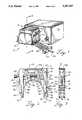
- FIG. 1is a perspective view of a pump in accordance with the invention
- FIG. 2is a front elevational view of a cartridge for the pump of FIG. 1;
- FIG. 3is a side elevational view of the cartridge of FIG. 2;
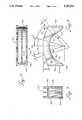
- FIG. 4is a sectional view taken substantially along line 4--4 in FIG. 1;
- FIG. 5is a sectional view taken substantially along line 5--5 in FIG. 4;
- FIG. 6is a sectional view taken substantially along line 6--6 in FIG. 4;
- FIG. 7is a sectional view taken substantially along line 7--7 in FIG. 6.
- FIG. 8is an enlarged front elevational view of the occlusion bed of the embodiment of FIGS. 1-7;
- FIG. 9is a side elevational view of the occlusion bed of FIG. 8;
- FIG. 10is a plan view of the occlusion bed of FIG. 8;
- FIG. 11is a front elevational view of an alternate occlusion bed
- FIG. 12is a side elevational view of the occlusion bed of FIG. 11;
- FIG. 13is a plan view of the occlusion bed of FIG. 11;
- FIG. 14is a sectional view taken substantially along line 14-14 in FIG. 11;
- FIG. 15is a qualitative graphic representation of fluid flow as a function of time, showing combined flow resulting from manifolding of two individual phase-offset flows.
- the preferred embodiment of the inventioncomprises a pump 10 which includes a frame 12, a rotor 14 supported for rotation on the frame, and a plurality of removable cartridges 16.
- Each of the cartridges 16is adapted for supporting an individual segment of flexible tubing 18 in engagement with the rotor as shown in FIG. 4. Peristaltic pumping through the tubing is effected by rotation of the rotor.
- the frame 12comprises a pair of forward and rear end walls 22 and 24 and a plurality of substantially horizontal rods 26, 27, 28 and 29 connecting the end walls.
- the outer rods 26, 28are positioned for cooperation with the cartridges 16 to maintain the cartridges in position on the frame as described below.
- the inner rods 27 and 29are bolted to the end walls of the frame to provide rigidity for the frame.
- the rear wall 24has means thereon for connecting the pump to a commercially available Masterflex pump drive/controller 30 available from Cole-Parmer Instrument Co.
- the rotor 14extends between the end walls 22, 24, and has a coupling means thereon to enable connection to a motor-driven shaft of the drive/controller 30.
- the rotor 14includes a plurality of rollers 32 supported between a pair of end members 34 which are fixed to a shaft 20. Each roller 32 is carried in a circular path about the axis of the rotor, and additionally rotates about its own axis of rotation.
- the pumpmay include an elastomeric guard 35 which partially shields the lower portion of the rotor 14.
- the pumpmay also include additional guards (not shown) which are disposed between the rollers 32 and are longitudinally coextensive therewith.
- Each of the removable cartridges 16comprises a three-sided frame 36 which includes first and second generally vertical side members 38 and 40, and a generally horizontal top member 42 connecting the side members.
- the frameis preferably a one-piece, integral, molded structure made of a suitable plastic.
- Each cartridge 16further includes a generally horizontal occlusion bed 44 disposed between the side members 38, 40 and spaced from the top member 42.
- the lower surface of the occlusion bed 44comprises a pressure surface 46 for engaging the tubing 18.
- the pressure surface 46comprises an arcuate region of maximum occlusion 47, which is configured substantially as a section of a cylinder and is radially the nearest portion of the pressure surface 46 to the rotor 14.
- the region of maximum occlusion 47preferably extends through an arc of greater than 360°/n, where "n" is equal to the number of rollers, so that, when an n-roller rotor is being used, at least one roller is compressing the tubing 18 against the region of maximum occlusion 47 at all times during operation.
- the region of maximum occlusion 47preferably extends through an arc of greater than 60° to enable the pump to function efficiently with a 6-roller rotor.
- the regions of maximum occlusion 47 of the pressure surfaces 46 on the respective cartridgesare offset relative to one another.
- the average flow over a period of timemay be the same, the instantaneous flow rates differ between cartridges having offset regions of maximum occlusion.
- the flow velocities for respective cartridges having offset regions of maximum occlusionare periodic functions of time which are non-synchronous with one another, but are otherwise similar or identical.
- phase shiftedor “phase-offset” are used herein to refer to flow velocities in respective lengths of tubing which vary as a function of time in a manner substantially similar to one another, except for a phase difference.
- non-synchronousrefers more generally to respective flow velocities which vary in phase or otherwise with respect to one another.
- the preferred angle of relative offsetis:
- zis equal to the number of occlusion bed configurations, i.e., the number of different angular orientations among the regions of maximum occlusion, and "k" is any non-negative integer less than n.
- the angle of relative offset in this caseis 30°.
- z>2the angle of relative offset between a first cartridge and a second cartridge is equal to 360(kz+1)/nz; the angle of relative offset between the second cartridge and a third cartridge is 360(kz+1)/nz; and so on.
- the value of kneed not be the same in every case.
- each cartridge 16is reversible with respect to the plane of the cartridge, and the region of maximum occlusion is disposed asymmetrically on the occlusion bed. Alternate cartridges have reverse orientation, resulting in offsetting of the regions of maximum occlusion.
- the occlusion bedsare configured such that the flow through each cartridge is phase offset with respect to flow through an oppositely oriented cartridge.
- the reversibility of the cartridgesenables the pump to be operated in another mode of operation in which all cartridges are oriented in the same manner, so as to provide synchronous flow through all of the flow channels.
- this mode of operationthe flow velocities at any point in time will be substantially equal, and the volume of fluid delivered through each of the lengths of tubing for a particular angular displacement of the rotor will be substantially equal.
- FIGS. 8-10illustrate in detail the occlusion bed 44 shown in FIGS. 1-7.
- a radial line bisecting the region of maximum occlusionis indicated at C.
- the verticalis indicated at V.
- the offset of the region of maximum occlusionis indicated by ⁇ , the included angle between line V and line C.
- the cartridge of FIG. 8is intended for use in the context of a 6-roller rotor and, accordingly, a 30° offset between adjacent cartridges is provided.
- ⁇15°.
- the region of maximum occlusion 47has a substantially uniform radius of curvature about the rotor axis of about 1 in.
- the region of maximum occlusionis substantially cylindrical, i.e., configured substantially as part of a cylinder.
- substantially planar regions 158 of equal dimensionextend tangentially therefrom, along a distance equal to about 0.2 in.
- the substantially planar tangential regions 158facilitate transition between the region of maximum occlusion and regions of lesser occlusion at either end thereof without unacceptably high dynamic loading on pump components.
- arcuate transition regions 160Disposed outwardly of the planar tangential regions at each end of the occlusion bed are arcuate transition regions 160 which are oriented to further decrease occlusion as the rotor proceeds away from the adjacent planar tangential region 158.
- the occlusion bedhas outwardly flared portions 162 at each of its ends at the locations at which the rollers engage and disengage the tubing.
- the occlusion bed 44may be engaged by rollers rotating either clockwise or counterclockwise with respect to FIG. 8.
- the rollerfirst engages the tubing at the outwardly flared region 162 of the occlusion bed at the left of FIG. 8, and the occlusion of the tubing progressively increases as the roller travels along the occlusion bed to the edge of the region of maximum occlusion 47.
- the rollerthen traverses an arc of 2 ⁇ degrees, maintaining maximum occlusion on the tubing.
- the distance between the roller and the occlusion surfacethen progressively increases until the roller reaches the flared end 162 of the occlusion bed at the right of FIG. 8, and loses contact with the tubing.
- the occlusion bed as illustrated in FIG. 8is preferably an injection-molded plastic structure comprising forward and rear vertical walls 150, a vertical reinforcing rib 152, and left and right vertical endwalls 154.
- Aligned slots 156are provided at one side of each of the front and rear walls to provide, by themselves or in conjunction with an inserted indicia, a visual reference to facilitate visual determination of the orientation of the occlusion bed.
- FIGS. 11-14illustrate an occlusion bed 44' in accordance with an alternate embodiment of the invention.
- the occlusion bed 44'is similar to that of FIGS. 8-10, but has a narrower configuration, i.e., a smaller dimension along the rotor axis, for accommodating a smaller diameter tubing, and has a configuration particularly configured for use in an 8-roller pump.
- primed reference numerals corresponding to the reference numerals of FIGS. 8-10are employed to indicate similar components.
- the rib 152'is slotted and has its upper surface raised slightly along camming surfaces 60' and 62' for tongue and groove engagement with a corresponding slot in the bottom surfaces of the wedges employed with the occlusion bed 44'.
- the rib 152'is contiguous with the front and rear walls.
- ⁇ '11.25° thereby providing a relative angular offset between relatively reversed cartridges of 22.5°.
- the smaller diameter of the tubingenables the planar regions 158' to be somewhat shorter, e.g., about 0.1 in.
- the angular dimension of the region of maximum occlusion 47' of the occlusion bed of a cartridge for use in an 8-roller pumpmight be configured so as to provide a ⁇ ' of less than 32.75°. Indeed, adequate performance would be expected so long as ⁇ '>22.5°.
- a plurality of pump output lengths of tubing 18are connected to a manifold 49 which has its outlet connected to a larger length of tubing 53 as illustrated in FIG. 1. While FIG. 1 illustrates four lengths of tubing 18 connected as a group to a single manifold, it will be appreciated that in other embodiments, a plurality of lengths of tubing may alternatively be connected pairwise to a plurality of manifolds, i.e., with only two cartridge outputs being combined at each manifold.
- FIG. 15The effect of combining two phase-offset pulsed flows is qualitatively illustrated in FIG. 15.
- the left-hand side of FIG. 15illustrates flow through relatively small diameter tubing, with volume plotted as a function of time. Flow through a first length of tubing, i.e., "Channel A,” is illustrated in the lowermost plot. Flow through a second length of tubing, i.e., "Channel B", is plotted immediately thereabove. The combined flow through the two channels is illustrated in the uppermost plot.
- the horizontal broken line in each plotrepresents zero flow, with negative flow volume representing flow in the direction opposite to that desired. Negative flow volume typically occurs in a length of tubing associated with a single cartridge as tubing occlusion rapidly decreases locally when a roller reaches the end of the occlusion bed.
- FIG. 15The right-hand side of FIG. 15 is a similar diagram, using the same conventions to illustrate flow volume as a function of time for relatively large diameter tubing.
- flow volume downstream from the peristaltic pumpmay be viewed as a periodic function of time, with each pulse being represented by a single substantially symmetrical wave.
- the number of pulses in a single 360° revolution of the rotoris equal to the number of rollers.
- the offsetting of occlusion in accordance with the inventionwherein the pulses are offset relative to one another in two flow channels, by one-half wavelength, results in elimination of reverse flow entirely, substantial reduction in the amplitude of pulsation, and doubling the frequency of pulsation.
- the occlusion bed 44is vertically movable in rectilinear motion, being mounted in slidable engagement with the inner surfaces 48, 50 of the side members 38 and 40 of the cartridge frame.
- the occlusion bedhas its vertical position controlled by an adjustment mechanism 52.
- the top of the occlusion bed 44is configured for camming engagement with a pair of wedges 54, 56 which are horizontally movable and which are in threaded engagement with an adjustment screw 58. More particularly, oppositely sloping camming surfaces 60, 62 of the occlusion bed 44 slidably engage the respective wedges 54 and 56.
- the adjustment screw 58has a pair of threaded portions 70, 72 of opposite hand, one threaded portion being in engagement with each of the wedges, so that rotation of the adjustment screw drives the wedges in opposite directions.
- Each of the camming surfaces 60 and 62, and the lower surface of each wedge,is inclined at an angle ⁇ of preferably 18.4°. This provides a sufficient range of vertical displacement of the occlusion bed over the range of travel of the wedges while also providing an acceptable mechanical advantage in adjustment, and maintaining friction between the wedges and the outer camming surfaces of the occlusion bed within acceptable limits.
- Each of the wedges 54, 56has a groove 64, 66 on its upper surface for slidably engaging a downwardly-projecting ridge 68 on the lower surface of the top 42 of the cartridge to provide a tongue-and-groove engagement.
- the wedgesare thereby constrained for rectilinear movement horizontally along a line extending between the side members 38, 40.
- the rigidity of the adjustment screw 58also aids in constraining the wedges.
- the occlusion bed 44may be installed or removed by applying pressure to pull the respective side members 38, 40 slightly apart.
- the side members 38, 40are sufficiently flexible and resilient to enable this to be accomplished manually.
- the cartridge frame 36is capable of receiving in the same manner occlusion beds of conventional, symmetrical configuration having regions of maximum occlusion extending at a uniform radius over an arc of over 120° for use in three-roller pumps.
- the cartridgeshave means for engaging the outer rods 26 and 28.
- the left side member 38 of the cartridge 16has a pair of legs 76 extending downwardly at its lower end. The legs have aligned notches 80 therein for engaging one of the support rods 26 or 28.
- the opposite side member 40has a locking mechanism 74 for engaging the other support rod 26 or 28.
- the locking mechanism 74is formed by the combination of a pair of legs 78 having notches 82 therein which face generally outwardly and downwardly on the side member, defining an internal radius for engaging the rod 28, and a resilient, flexible member 84 having legs 88 with inwardly-facing notches 86 thereon for engaging the outer, lower surface of the rod 28.
- the legs 78 and 88have downwardly diverging camming surfaces 90, 92 formed thereon to facilitate locking of the cartridge 16 in place.
- the cartridgemay be placed "on line” by first engaging the notches 80 on the left side legs 78 with one of the rods 26, and pivoting the cartridge downward until the resilient member 84 is cammed outwardly, then snaps back into its original position, locking the cartridge in place.
- a handle 91is provided to facilitate manipulation of the cartridge 16.
- a lever 89may be provided for camming the flexible member 84 outwardly.
- the illustrated lever 89comprises a wire bail having its ends pivotally mounted on the side member 40 of the frame.
- the lever 89has two side portions extending upwardly from the ends to a horizontal portion that extends across the width of the cartridge 16. Each of the side portions extends substantially vertically upward for a short distance, then curves through an obtuse angle to extend outwardly and upwardly over the handle 91.
- the flexible member 84is fixed to the adjacent portion of the cartridge frame by engagement between a pair of legs 134 at the upper end of member 84 and corresponding slots 136 in the frame; and by engagement between a notch or recess 138 formed between the legs 134 and an interfitting boss 140 on the cartridge frame 36.
- the flexible member 84has a slot 142 therein through which a handle 124 of the tubing retainer extends.
- the pump controller 30contains a variable speed electric motor and a control circuit for adjusting the motor speed.
- the motorrotates a shaft coupled to the rotor 14.
- the rear end wall 24 of the pump framehas four screw holes therein, each with a counterbore for receiving a screw head. The screw holes align with threaded bores opening on the front surface of the pump control unit.
- a knob 108enables manual adjustment of the pump speed.
- a peristaltic pumpDuring operation of a peristaltic pump, longitudinal force is exerted on the segment of tubing within the pump, tending to pull the tubing through the pump in the direction of rotation of the rotor. To prevent such displacement of the tubing, in some instances clips or stops are attached to the tubing for engagement with the exterior of the pump housing. In other cases, means are provided on the pump itself to constrain the tubing against longitudinal movement. In the illustrated embodiment of the invention, a tubing retainer mechanism is provided on each cartridge.
- each of the tubing retainers 110exerts downward pressure on the tubing, holding it between a generally V-shaped notch 112 at the lower end of the tubing retainer and a respective one of the rods 26, 28.
- the V-shaped notch 112has a corner edge thereon formed by the intersection at acute angle of a substantially vertical outer surface with a sloping, V-shaped bottom surface. The edge at the intersection has a radius of about 0.01 in. The dimension of the bottom surface in the direction of the length of the tubing is about 0.25 in.
- Each of the tubing retainers 110is constrained by an internal channel 114 in its associated side member 38 or 40 of the cartridge 16 so that it has one degree of freedom only, being movable only in linear vertical motion.
- Each of the illustrated tubing retainers 110has an elongated body 128 extending into the channel 114.
- the bodyincludes a pair of spaced legs 126 which extend vertically upward from the lower notched portion of the retainer, in sliding contact with the channel. The legs may be connected by a link (not shown) across their upper ends.
- the retainerincludes a cantilevered arm 116 having a plurality of teeth 118 thereon for engaging complementary teeth 120 on the interior of a slot 122.
- the slot 122is disposed between the channel 114 and the exterior of the cartridge 16.
- the arm 116is made of a flexible, resilient material, and is movable between a first, undeformed position in which it is substantially vertical, and a second position in which it is deflected inward. When in its undeformed position, the arm 116 has its teeth 118 in locking engagement with the teeth 120 on the slot. When adjustment is desired, a projection or handle 124 on the arm 116 is pressed inward by the user, deflecting the upper end of the arm 116 inward between the legs 126 out of engagement with the teeth 120. The vertical position of the tubing retainer 110 may then be adjusted as desired. When the desired position is reached, the arm 116 need only be released and allowed to return to its undeformed position. This locks the retainer 110 in its new position.
- the illustrated teeth 118 and 120are configured to facilitate downward movement of the tubing retainer 110 and provide added mechanical resistance to upward movement, thereby avoiding unintended upward displacement of the tubing retainer due to pressure and pulsation attendant to the pumping operation.
- the internal channel 114has relatively smooth sides, and is disposed in a different plane from the slot 122. This provides for smooth sliding of the tubing retainer when the arm 116 is depressed.
- Stops 130are provided on the interiors of the side members 38, 40 to limit downward travel of the occlusion bed. While the pump 10 is in use, upward pressure on the occlusion bed maintains the occlusion bed in place. When the cartridge 16 is removed from the pump 10, the stops 130 act to prevent the occlusion bed from being separated from the cartridge frame 36.
- the occlusion settingmay be used to fine tune the flow rate. Increases in occlusion produce increases in output pressure and flow rate over a certain range, independent of the rotor speed. The degree of occlusion also affects the amplitude of pulsation in the flow rate. Additionally, increased occlusion decreases tubing life due to the increased strain experienced by the tubing with increased occlusion.
- Indicia 103are preferably provided on a label 105 on the side of the cartridge frame to enable comparison of wedge positions with predetermined reference points, thus facilitating repetition of occlusion settings. In the absence of indicia, the number of visible threads on the adjustment screw 58 adjacent each of the wedges may be viewed and counted to provide a visual reference.
Landscapes
- Engineering & Computer Science (AREA)
- Mechanical Engineering (AREA)
- General Engineering & Computer Science (AREA)
- Reciprocating Pumps (AREA)
Abstract
Description
360° (kz+1)/nz
Claims (12)
Priority Applications (6)
| Application Number | Priority Date | Filing Date | Title |
|---|---|---|---|
| US07/955,925US5257917A (en) | 1992-10-02 | 1992-10-02 | Peristaltic pump having means for reducing flow pulsation |
| EP93923158AEP0619859B1 (en) | 1992-10-02 | 1993-09-28 | Peristaltic pump having means for reducing flow pulsation |
| CA002123695ACA2123695C (en) | 1992-10-02 | 1993-09-28 | Peristaltic pump having means for reducing flow pulsation |
| DE69307867TDE69307867T2 (en) | 1992-10-02 | 1993-09-28 | PERISTALTIC PUMP WITH AGENT FOR REDUCING LIQUID PULSATIONS |
| PCT/US1993/009254WO1994008138A1 (en) | 1992-10-02 | 1993-09-28 | Peristaltic pump having means for reducing flow pulsation |
| JP50927694AJP3432512B2 (en) | 1992-10-02 | 1993-09-28 | Peristaltic pump with means for reducing flow perturbation |
Applications Claiming Priority (1)
| Application Number | Priority Date | Filing Date | Title |
|---|---|---|---|
| US07/955,925US5257917A (en) | 1992-10-02 | 1992-10-02 | Peristaltic pump having means for reducing flow pulsation |
Publications (1)
| Publication Number | Publication Date |
|---|---|
| US5257917Atrue US5257917A (en) | 1993-11-02 |
Family
ID=25497546
Family Applications (1)
| Application Number | Title | Priority Date | Filing Date |
|---|---|---|---|
| US07/955,925Expired - LifetimeUS5257917A (en) | 1992-10-02 | 1992-10-02 | Peristaltic pump having means for reducing flow pulsation |
Country Status (6)
| Country | Link |
|---|---|
| US (1) | US5257917A (en) |
| EP (1) | EP0619859B1 (en) |
| JP (1) | JP3432512B2 (en) |
| CA (1) | CA2123695C (en) |
| DE (1) | DE69307867T2 (en) |
| WO (1) | WO1994008138A1 (en) |
Cited By (78)
| Publication number | Priority date | Publication date | Assignee | Title |
|---|---|---|---|---|
| US5431307A (en)* | 1994-08-26 | 1995-07-11 | Gencorp Inc. | Dispensing plural components |
| US5443451A (en)* | 1993-11-17 | 1995-08-22 | Baxter International Inc. | Peristaltic pumping assembly |
| US5460493A (en)* | 1993-11-17 | 1995-10-24 | Baxter International Inc. | Organizer frame for holding an array of flexible tubing in alignment with one or more peristaltic pump rotors |
| US5460490A (en)* | 1994-05-19 | 1995-10-24 | Linvatec Corporation | Multi-purpose irrigation/aspiration pump system |
| US5640756A (en)* | 1995-02-08 | 1997-06-24 | Gencorp Inc. | Manufacturing system |
| US5846061A (en)* | 1996-11-08 | 1998-12-08 | Board Of Trustees Of Michigan State University | Peristaltic metering pump |
| USD403259S (en) | 1997-06-06 | 1998-12-29 | Miura Co., Ltd. | Colorimeter |
| USD403604S (en)* | 1997-09-29 | 1999-01-05 | Yoshitami Tsubota | Reagent cartridge for colorimeter |
| US5857843A (en)* | 1995-10-20 | 1999-01-12 | Harvest Technologies Llc | Peristaltic pump with removable rotor |
| WO1999014497A1 (en)* | 1997-09-18 | 1999-03-25 | Fsi International | Peristaltic pump with continuous and non pulsating discharge flow |
| US5890626A (en)* | 1996-08-12 | 1999-04-06 | Imi Wilshire Inc. | Remote juice dispenser |
| US5927956A (en)* | 1998-09-01 | 1999-07-27 | Linvatec Corporation | Peristaltic pump tubing system with latching cassette |
| US5938414A (en)* | 1996-03-27 | 1999-08-17 | Miura Co., Ltd. | Liquid feeding apparatus having a cassette accommodating an elastic tube |
| WO2000070225A1 (en)* | 1999-05-12 | 2000-11-23 | G John Andersen | Peristaltic fluid pump |
| EP1136088A1 (en)* | 1995-06-28 | 2001-09-26 | Medex, Inc. | Medical pressure transducer with sliding components |
| US6393338B1 (en) | 2000-03-17 | 2002-05-21 | Tadeusz Kemnitz | Apparatus and control method for accurate rotary peristaltic pump filling |
| US6419466B1 (en)* | 1999-12-17 | 2002-07-16 | Bunn-O-Matic Corporation | Pump |
| WO2003067089A1 (en)* | 2002-02-08 | 2003-08-14 | Nextgen Sciences Ltd | Fluid pump |
| US20040057856A1 (en)* | 2002-09-23 | 2004-03-25 | Ismatec Sa | Hose cartridge for a peristaltic pump |
| US20040191086A1 (en)* | 2003-03-31 | 2004-09-30 | Paukovits Edward J. | Disposable fluid delivery system |
| US20050047946A1 (en)* | 2003-08-25 | 2005-03-03 | Hewlett-Packard Development Company, L.P. | Peristaltic pump |
| US20050069419A1 (en)* | 2003-09-29 | 2005-03-31 | Cull Laurence J. | Peristaltic pump with air venting via the movement of a pump head or a backing plate during surgery |
| US20050069437A1 (en)* | 2003-09-29 | 2005-03-31 | Michael Mittelstein | Peristaltic pump with a moveable pump head |
| US20050238516A1 (en)* | 2004-04-27 | 2005-10-27 | Hewlett-Packard Development Company, Lp | Peristaltic pump |
| US20050238515A1 (en)* | 2004-04-27 | 2005-10-27 | Hewlett-Packard Development Company., L.P. | Peristaltic pump |
| US20050254879A1 (en)* | 2002-06-13 | 2005-11-17 | Gundersen Robert J | Adjustable flow texture sprayer with peristaltic pump |
| US20060228240A1 (en)* | 2005-03-30 | 2006-10-12 | Lancer Partnership, Ltd. | Method and apparatus for a linear peristaltic pump |
| US20060245964A1 (en)* | 2003-04-29 | 2006-11-02 | Loren Hagen | Pulseless peristaltic pump |
| US20070068966A1 (en)* | 2005-09-23 | 2007-03-29 | Orzech Thomas S | Food dispenser with pump for easy loading of containers therein |
| US7238164B2 (en) | 2002-07-19 | 2007-07-03 | Baxter International Inc. | Systems, methods and apparatuses for pumping cassette-based therapies |
| US20070183913A1 (en)* | 2006-01-11 | 2007-08-09 | Claude Voyeux | Peristaltic pump including an elastically displaceable locking plate |
| US20070217932A1 (en)* | 2004-06-22 | 2007-09-20 | Claude Voyeux | Method and system for providing adjustable compression force on a tube in a peristaltic pump |
| US20070243088A1 (en)* | 2006-04-12 | 2007-10-18 | Cole-Parmer Instrument Company | Marked Tube For A Peristaltic Pump |
| US20080145249A1 (en)* | 2005-03-17 | 2008-06-19 | Smisson-Cartledge Biomedical Llc | Dynamic Range Motor For A Pump Device |
| US20080239640A1 (en)* | 2007-03-29 | 2008-10-02 | Samsung Electronics Co., Ltd. | Support device for display unit and display unit having the same |
| US20090016915A1 (en)* | 2005-03-30 | 2009-01-15 | Medical Service S.R.L. | Pump, especially for the blood treatment |
| USD587365S1 (en)* | 2006-11-13 | 2009-02-24 | Q-Core Ltd. | Control unit for a peristaltic pump |
| USD587802S1 (en)* | 2006-11-13 | 2009-03-03 | Q-Core Ltd. | Control unit for a peristaltic pump |
| WO2009042181A1 (en)* | 2007-09-27 | 2009-04-02 | Delphi Technologies, Inc. | Peristaltic pump and removable cassette therefor |
| WO2009105436A1 (en)* | 2008-02-22 | 2009-08-27 | Medtronic Xomed, Inc. | Method and system for loading of tubing into a pumping device |
| US20090214366A1 (en)* | 2008-02-27 | 2009-08-27 | Smith & Nephew, Inc. | Peristaltic Pumping Apparatus and Method |
| US7731689B2 (en) | 2007-02-15 | 2010-06-08 | Baxter International Inc. | Dialysis system having inductive heating |
| WO2010129128A1 (en)* | 2009-05-06 | 2010-11-11 | Alcon Research, Ltd. | Multiple segmented peristaltic pump and cassette |
| US20100301071A1 (en)* | 2007-12-05 | 2010-12-02 | Bunn-O-Matic Corporation | Peristaltic pump |
| US20110180172A1 (en)* | 2010-01-22 | 2011-07-28 | Blu-White Industries, Inc. | High pressure, high flow rate tubing assembly for a positive displacement pump |
| US7998115B2 (en) | 2007-02-15 | 2011-08-16 | Baxter International Inc. | Dialysis system having optical flowrate detection |
| US20110313358A1 (en)* | 2009-01-30 | 2011-12-22 | Nestec S.A. | Infusion pump cassette with anti-free-flow valve mechanism |
| US20120130309A1 (en)* | 2009-01-30 | 2012-05-24 | Nestec S.A. | Infusion pump cassette with ant i -free -flow valve mechanism |
| US8323231B2 (en) | 2000-02-10 | 2012-12-04 | Baxter International, Inc. | Method and apparatus for monitoring and controlling peritoneal dialysis therapy |
| US8361023B2 (en) | 2007-02-15 | 2013-01-29 | Baxter International Inc. | Dialysis system with efficient battery back-up |
| US20130056497A1 (en)* | 2011-09-07 | 2013-03-07 | Gojo Industries, Inc. | Wiper foam pump, refill unit & dispenser for same |
| US20130071272A1 (en)* | 2011-09-19 | 2013-03-21 | Jeffery T. Juretich | Peristaltic pump cassette and method of installing same |
| US8545435B2 (en) | 2002-01-03 | 2013-10-01 | Baxter International, Inc. | Method and apparatus for providing medical treatment therapy based on calculated demand |
| US8558964B2 (en) | 2007-02-15 | 2013-10-15 | Baxter International Inc. | Dialysis system having display with electromagnetic compliance (“EMC”) seal |
| US20140086771A1 (en)* | 2012-09-26 | 2014-03-27 | Capmatic Ltee | Peristaltic pump |
| US8870812B2 (en) | 2007-02-15 | 2014-10-28 | Baxter International Inc. | Dialysis system having video display with ambient light adjustment |
| CN104641217A (en)* | 2012-05-30 | 2015-05-20 | 艾瑞斯国际有限公司 | Flow Cytometry |
| US9126219B2 (en) | 2013-03-15 | 2015-09-08 | Alcon Research, Ltd. | Acoustic streaming fluid ejector |
| US20150300348A1 (en)* | 2014-04-13 | 2015-10-22 | David T. Bach | Precision Fluid Dispensing Using Peristaltic Roller Control |
| US9518576B1 (en)* | 2010-07-15 | 2016-12-13 | Elemental Scientific, Inc. | Peristaltic pump |
| US9545337B2 (en) | 2013-03-15 | 2017-01-17 | Novartis Ag | Acoustic streaming glaucoma drainage device |
| GB2542191A (en)* | 2015-09-11 | 2017-03-15 | Watson-Marlow Ltd | A Peristaltic pump |
| CN106704156A (en)* | 2016-11-30 | 2017-05-24 | 重庆速腾机械制造有限公司 | Conveying pump capable of controlling flow of multipath coaxial fluid |
| CN106762569A (en)* | 2016-11-30 | 2017-05-31 | 重庆速腾机械制造有限公司 | A kind of multichannel coaxial flow delivery pump |
| US9693896B2 (en) | 2013-03-15 | 2017-07-04 | Novartis Ag | Systems and methods for ocular surgery |
| US9746412B2 (en) | 2012-05-30 | 2017-08-29 | Iris International, Inc. | Flow cytometer |
| US9750638B2 (en) | 2013-03-15 | 2017-09-05 | Novartis Ag | Systems and methods for ocular surgery |
| US9777720B2 (en) | 2013-03-14 | 2017-10-03 | Blue-White Industries, Ltd. | High pressure, high flow rate tubing assembly and adapter for a positive displacement pump |
| US9861522B2 (en) | 2009-12-08 | 2018-01-09 | Alcon Research, Ltd. | Phacoemulsification hand piece with integrated aspiration pump |
| US9909579B2 (en) | 2014-06-09 | 2018-03-06 | Blue-White Industries, Ltd. | Overmolded tubing assembly and adapter for a positive displacement pump |
| US9915274B2 (en) | 2013-03-15 | 2018-03-13 | Novartis Ag | Acoustic pumps and systems |
| US9962288B2 (en) | 2013-03-07 | 2018-05-08 | Novartis Ag | Active acoustic streaming in hand piece for occlusion surge mitigation |
| US20180238318A1 (en)* | 2016-07-29 | 2018-08-23 | W.O.M. World Of Medicine Gmbh | Hose cartridge for a peristaltic pump having elastic legs |
| US10182940B2 (en) | 2012-12-11 | 2019-01-22 | Novartis Ag | Phacoemulsification hand piece with integrated aspiration and irrigation pump |
| US10252271B2 (en)* | 2014-04-30 | 2019-04-09 | University Of Southampton | Methods and apparatus for generating droplets |
| US11179516B2 (en) | 2017-06-22 | 2021-11-23 | Baxter International Inc. | Systems and methods for incorporating patient pressure into medical fluid delivery |
| US11578716B2 (en) | 2010-01-22 | 2023-02-14 | Blue-White Industries, Ltd. | Overmolded tubing assembly and adapter for a positive displacement pump |
| US12263292B2 (en) | 2018-12-19 | 2025-04-01 | Boston Scientific Scimed, Inc. | Dampening element for fluid management system |
Families Citing this family (7)
| Publication number | Priority date | Publication date | Assignee | Title |
|---|---|---|---|---|
| US5688112A (en)* | 1996-02-22 | 1997-11-18 | Garay; Thomas William | Rotor axis aligned tube and outlet for a peristaltic pump system |
| JP5306785B2 (en)* | 2008-11-19 | 2013-10-02 | 日機装株式会社 | Pump device, biological component measuring device, and artificial pancreas device |
| RU2015122432A (en)* | 2012-12-24 | 2017-01-27 | Фрезениус Медикал Кеа Холдингс, Инк. | ORTATIVE DIALYSIS DEVICE WITH AN IMPROVED HEATING SYSTEM FOR TANKS |
| JP6216632B2 (en)* | 2013-12-12 | 2017-10-18 | 株式会社日立製作所 | Cell culture equipment |
| KR102071646B1 (en)* | 2018-07-26 | 2020-01-31 | (주)오토일렉스 | tube pump |
| US11213460B2 (en) | 2018-09-19 | 2022-01-04 | Vesco Medical Llc | Connectors for infusion pump feeding sets |
| JP2021006705A (en)* | 2019-06-28 | 2021-01-21 | アトー株式会社 | Pump device |
Citations (23)
| Publication number | Priority date | Publication date | Assignee | Title |
|---|---|---|---|---|
| US1922196A (en)* | 1932-03-17 | 1933-08-15 | Nordberg Manufacturing Co | Pump |
| US2804023A (en)* | 1954-11-29 | 1957-08-27 | Mr Robot Inc | Pump |
| US2913992A (en)* | 1957-10-29 | 1959-11-24 | John Blue Company Inc | Hose pump |
| US3072296A (en)* | 1958-12-31 | 1963-01-08 | Technicon Instr | Pumping apparatus |
| US3431864A (en)* | 1966-12-22 | 1969-03-11 | Charles B Jones Jr | Peristaltic pump |
| US3723030A (en)* | 1971-03-03 | 1973-03-27 | Buchler Instr Division | Peristaltic pump with stacked components |
| US3832096A (en)* | 1971-03-03 | 1974-08-27 | Buchler Instr | Multitube peristaltic pump with individual programming control |
| US3876340A (en)* | 1972-08-09 | 1975-04-08 | Rank Organisation Ltd | Peristaltic pump having pivotal reaction means |
| US3951570A (en)* | 1973-02-21 | 1976-04-20 | Gianfranco De Biaggi | Pumping unit for extracorporeal haematic circulation, in particular in artificial kidneys |
| US4060348A (en)* | 1975-07-01 | 1977-11-29 | Bioengineering Research S.A. | Roller pump carrying out alternate pumping operations, particularly suited to extra-corporeal blood circulation |
| US4233001A (en)* | 1979-02-28 | 1980-11-11 | Peerless Electronics Research Corporation | Peristaltic pump |
| US4289459A (en)* | 1979-08-13 | 1981-09-15 | Neeley William E | Proportioning pump |
| WO1982003427A1 (en)* | 1981-04-07 | 1982-10-14 | Kristensen Hans Saustrup | A roller pump,preferably for implantation |
| WO1983001984A1 (en)* | 1981-11-25 | 1983-06-09 | Charles Henry Hackman | Rotary peristaltic pump |
| US4397639A (en)* | 1980-04-24 | 1983-08-09 | Ferring Arzneimittel Gmbh | Device for the intermittent pulsatory application of fluid medicaments |
| US4424009A (en)* | 1979-07-12 | 1984-01-03 | Noord-Nederlandsche Machinefabriek B.V. | Peristaltic pump |
| US4496295A (en)* | 1982-03-22 | 1985-01-29 | King Oswald M | Peristaltic pumps |
| US4568254A (en)* | 1983-07-06 | 1986-02-04 | Horiba, Ltd. | Tubing pump |
| US4673334A (en)* | 1984-05-25 | 1987-06-16 | Isco, Inc. | Peristaltic pump |
| US4834630A (en)* | 1987-10-27 | 1989-05-30 | Godwin Darwin D | Peristaltic pump |
| US4886431A (en)* | 1988-04-29 | 1989-12-12 | Cole-Parmer Instrument Company | Peristaltic pump having independently adjustable cartridges |
| US4997347A (en)* | 1990-01-12 | 1991-03-05 | Autotrol Corporation | Peristaltic motor |
| US5011378A (en)* | 1988-07-08 | 1991-04-30 | I-Flow Corporation | Pump tube mount and cartridge for infusion pump |
Family Cites Families (3)
| Publication number | Priority date | Publication date | Assignee | Title |
|---|---|---|---|---|
| GB1595901A (en)* | 1978-02-10 | 1981-08-19 | Ici Ltd | Peristaltic pump and agricultural/horticultural machine |
| SE445943B (en)* | 1981-05-27 | 1986-07-28 | Per Borgstrom | peristaltic pump |
| FR2644522B1 (en)* | 1989-03-14 | 1993-05-14 | Malbec Edouard | PERISTALTIC PUMP |
- 1992
- 1992-10-02USUS07/955,925patent/US5257917A/ennot_activeExpired - Lifetime
- 1993
- 1993-09-28CACA002123695Apatent/CA2123695C/ennot_activeExpired - Fee Related
- 1993-09-28EPEP93923158Apatent/EP0619859B1/ennot_activeExpired - Lifetime
- 1993-09-28DEDE69307867Tpatent/DE69307867T2/ennot_activeExpired - Fee Related
- 1993-09-28JPJP50927694Apatent/JP3432512B2/ennot_activeExpired - Fee Related
- 1993-09-28WOPCT/US1993/009254patent/WO1994008138A1/enactiveIP Right Grant
Patent Citations (23)
| Publication number | Priority date | Publication date | Assignee | Title |
|---|---|---|---|---|
| US1922196A (en)* | 1932-03-17 | 1933-08-15 | Nordberg Manufacturing Co | Pump |
| US2804023A (en)* | 1954-11-29 | 1957-08-27 | Mr Robot Inc | Pump |
| US2913992A (en)* | 1957-10-29 | 1959-11-24 | John Blue Company Inc | Hose pump |
| US3072296A (en)* | 1958-12-31 | 1963-01-08 | Technicon Instr | Pumping apparatus |
| US3431864A (en)* | 1966-12-22 | 1969-03-11 | Charles B Jones Jr | Peristaltic pump |
| US3723030A (en)* | 1971-03-03 | 1973-03-27 | Buchler Instr Division | Peristaltic pump with stacked components |
| US3832096A (en)* | 1971-03-03 | 1974-08-27 | Buchler Instr | Multitube peristaltic pump with individual programming control |
| US3876340A (en)* | 1972-08-09 | 1975-04-08 | Rank Organisation Ltd | Peristaltic pump having pivotal reaction means |
| US3951570A (en)* | 1973-02-21 | 1976-04-20 | Gianfranco De Biaggi | Pumping unit for extracorporeal haematic circulation, in particular in artificial kidneys |
| US4060348A (en)* | 1975-07-01 | 1977-11-29 | Bioengineering Research S.A. | Roller pump carrying out alternate pumping operations, particularly suited to extra-corporeal blood circulation |
| US4233001A (en)* | 1979-02-28 | 1980-11-11 | Peerless Electronics Research Corporation | Peristaltic pump |
| US4424009A (en)* | 1979-07-12 | 1984-01-03 | Noord-Nederlandsche Machinefabriek B.V. | Peristaltic pump |
| US4289459A (en)* | 1979-08-13 | 1981-09-15 | Neeley William E | Proportioning pump |
| US4397639A (en)* | 1980-04-24 | 1983-08-09 | Ferring Arzneimittel Gmbh | Device for the intermittent pulsatory application of fluid medicaments |
| WO1982003427A1 (en)* | 1981-04-07 | 1982-10-14 | Kristensen Hans Saustrup | A roller pump,preferably for implantation |
| WO1983001984A1 (en)* | 1981-11-25 | 1983-06-09 | Charles Henry Hackman | Rotary peristaltic pump |
| US4496295A (en)* | 1982-03-22 | 1985-01-29 | King Oswald M | Peristaltic pumps |
| US4568254A (en)* | 1983-07-06 | 1986-02-04 | Horiba, Ltd. | Tubing pump |
| US4673334A (en)* | 1984-05-25 | 1987-06-16 | Isco, Inc. | Peristaltic pump |
| US4834630A (en)* | 1987-10-27 | 1989-05-30 | Godwin Darwin D | Peristaltic pump |
| US4886431A (en)* | 1988-04-29 | 1989-12-12 | Cole-Parmer Instrument Company | Peristaltic pump having independently adjustable cartridges |
| US5011378A (en)* | 1988-07-08 | 1991-04-30 | I-Flow Corporation | Pump tube mount and cartridge for infusion pump |
| US4997347A (en)* | 1990-01-12 | 1991-03-05 | Autotrol Corporation | Peristaltic motor |
Non-Patent Citations (2)
| Title |
|---|
| Pages from Cole Parmer 1987 1988 Catalog.* |
| Pages from Cole-Parmer 1987-1988 Catalog. |
Cited By (149)
| Publication number | Priority date | Publication date | Assignee | Title |
|---|---|---|---|---|
| US6186752B1 (en) | 1993-11-17 | 2001-02-13 | Baxter International Inc. | Peristaltic pumping apparatus with tubing organizer |
| US5443451A (en)* | 1993-11-17 | 1995-08-22 | Baxter International Inc. | Peristaltic pumping assembly |
| US5460493A (en)* | 1993-11-17 | 1995-10-24 | Baxter International Inc. | Organizer frame for holding an array of flexible tubing in alignment with one or more peristaltic pump rotors |
| US5460490A (en)* | 1994-05-19 | 1995-10-24 | Linvatec Corporation | Multi-purpose irrigation/aspiration pump system |
| US5431307A (en)* | 1994-08-26 | 1995-07-11 | Gencorp Inc. | Dispensing plural components |
| US5640756A (en)* | 1995-02-08 | 1997-06-24 | Gencorp Inc. | Manufacturing system |
| EP1136088A1 (en)* | 1995-06-28 | 2001-09-26 | Medex, Inc. | Medical pressure transducer with sliding components |
| US5857843A (en)* | 1995-10-20 | 1999-01-12 | Harvest Technologies Llc | Peristaltic pump with removable rotor |
| US5938414A (en)* | 1996-03-27 | 1999-08-17 | Miura Co., Ltd. | Liquid feeding apparatus having a cassette accommodating an elastic tube |
| US5890626A (en)* | 1996-08-12 | 1999-04-06 | Imi Wilshire Inc. | Remote juice dispenser |
| US5846061A (en)* | 1996-11-08 | 1998-12-08 | Board Of Trustees Of Michigan State University | Peristaltic metering pump |
| USD403259S (en) | 1997-06-06 | 1998-12-29 | Miura Co., Ltd. | Colorimeter |
| WO1999014497A1 (en)* | 1997-09-18 | 1999-03-25 | Fsi International | Peristaltic pump with continuous and non pulsating discharge flow |
| US6099272A (en)* | 1997-09-18 | 2000-08-08 | Fsi International | Peristaltic pump with flow control |
| USD403604S (en)* | 1997-09-29 | 1999-01-05 | Yoshitami Tsubota | Reagent cartridge for colorimeter |
| US5927956A (en)* | 1998-09-01 | 1999-07-27 | Linvatec Corporation | Peristaltic pump tubing system with latching cassette |
| US6551080B2 (en) | 1999-05-12 | 2003-04-22 | John G. Andersen | Unsynchronized phase operation of peristaltic pump rollers |
| AU770310B2 (en)* | 1999-05-12 | 2004-02-19 | Dia Medical A/S | Peristaltic fluid pump |
| JP2002544439A (en)* | 1999-05-12 | 2002-12-24 | ジー. ジョン アンデルセン, | Peristaltic pump |
| WO2000070225A1 (en)* | 1999-05-12 | 2000-11-23 | G John Andersen | Peristaltic fluid pump |
| US6419466B1 (en)* | 1999-12-17 | 2002-07-16 | Bunn-O-Matic Corporation | Pump |
| US10322224B2 (en) | 2000-02-10 | 2019-06-18 | Baxter International Inc. | Apparatus and method for monitoring and controlling a peritoneal dialysis therapy |
| US9474842B2 (en) | 2000-02-10 | 2016-10-25 | Baxter International Inc. | Method and apparatus for monitoring and controlling peritoneal dialysis therapy |
| US8323231B2 (en) | 2000-02-10 | 2012-12-04 | Baxter International, Inc. | Method and apparatus for monitoring and controlling peritoneal dialysis therapy |
| US6393338B1 (en) | 2000-03-17 | 2002-05-21 | Tadeusz Kemnitz | Apparatus and control method for accurate rotary peristaltic pump filling |
| US8545435B2 (en) | 2002-01-03 | 2013-10-01 | Baxter International, Inc. | Method and apparatus for providing medical treatment therapy based on calculated demand |
| WO2003067089A1 (en)* | 2002-02-08 | 2003-08-14 | Nextgen Sciences Ltd | Fluid pump |
| US20050254879A1 (en)* | 2002-06-13 | 2005-11-17 | Gundersen Robert J | Adjustable flow texture sprayer with peristaltic pump |
| US7238164B2 (en) | 2002-07-19 | 2007-07-03 | Baxter International Inc. | Systems, methods and apparatuses for pumping cassette-based therapies |
| US20040057856A1 (en)* | 2002-09-23 | 2004-03-25 | Ismatec Sa | Hose cartridge for a peristaltic pump |
| US7214038B2 (en)* | 2002-09-23 | 2007-05-08 | Ismatec Sa | Hose cartridge for a peristaltic pump |
| US8206338B2 (en) | 2002-12-31 | 2012-06-26 | Baxter International Inc. | Pumping systems for cassette-based dialysis |
| US7744554B2 (en) | 2002-12-31 | 2010-06-29 | Baxter International Inc. | Cassette alignment and integrity testing for dialysis systems |
| US6890161B2 (en) | 2003-03-31 | 2005-05-10 | Assistive Technology Products, Inc. | Disposable fluid delivery system |
| US20040191086A1 (en)* | 2003-03-31 | 2004-09-30 | Paukovits Edward J. | Disposable fluid delivery system |
| US7645127B2 (en) | 2003-04-29 | 2010-01-12 | Loren Hagen | Pulseless peristaltic pump |
| US20060245964A1 (en)* | 2003-04-29 | 2006-11-02 | Loren Hagen | Pulseless peristaltic pump |
| US20050047946A1 (en)* | 2003-08-25 | 2005-03-03 | Hewlett-Packard Development Company, L.P. | Peristaltic pump |
| US7118203B2 (en) | 2003-08-25 | 2006-10-10 | Hewlett-Packard Development Company, L.P. | Peristaltic pump |
| US7445436B2 (en) | 2003-09-29 | 2008-11-04 | Bausch & Lomb Incorporated | Peristaltic pump with a moveable pump head |
| US7168930B2 (en) | 2003-09-29 | 2007-01-30 | Bausch & Lomb Incorporated | Peristaltic pump with air venting via the movement of a pump head or a backing plate during surgery |
| US20050069419A1 (en)* | 2003-09-29 | 2005-03-31 | Cull Laurence J. | Peristaltic pump with air venting via the movement of a pump head or a backing plate during surgery |
| US20050069437A1 (en)* | 2003-09-29 | 2005-03-31 | Michael Mittelstein | Peristaltic pump with a moveable pump head |
| US8393879B2 (en) | 2004-04-27 | 2013-03-12 | Hewlett-Packard Development Company, L.P. | Peristaltic pump |
| US7591639B2 (en) | 2004-04-27 | 2009-09-22 | Hewlett-Packard Development Company, L.P. | Peristaltic pump |
| US20050238515A1 (en)* | 2004-04-27 | 2005-10-27 | Hewlett-Packard Development Company., L.P. | Peristaltic pump |
| US20050238516A1 (en)* | 2004-04-27 | 2005-10-27 | Hewlett-Packard Development Company, Lp | Peristaltic pump |
| US20070217932A1 (en)* | 2004-06-22 | 2007-09-20 | Claude Voyeux | Method and system for providing adjustable compression force on a tube in a peristaltic pump |
| US8360737B2 (en)* | 2005-03-17 | 2013-01-29 | Smisson-Cartledge Biomedical Llc | Dynamic range motor for a pump device |
| US20080145249A1 (en)* | 2005-03-17 | 2008-06-19 | Smisson-Cartledge Biomedical Llc | Dynamic Range Motor For A Pump Device |
| US20060228240A1 (en)* | 2005-03-30 | 2006-10-12 | Lancer Partnership, Ltd. | Method and apparatus for a linear peristaltic pump |
| US20090016915A1 (en)* | 2005-03-30 | 2009-01-15 | Medical Service S.R.L. | Pump, especially for the blood treatment |
| US8545197B2 (en)* | 2005-03-30 | 2013-10-01 | Medical Service S.R.L. | Pump, especially for blood treatment |
| US20070068966A1 (en)* | 2005-09-23 | 2007-03-29 | Orzech Thomas S | Food dispenser with pump for easy loading of containers therein |
| US20070183913A1 (en)* | 2006-01-11 | 2007-08-09 | Claude Voyeux | Peristaltic pump including an elastically displaceable locking plate |
| US20070243088A1 (en)* | 2006-04-12 | 2007-10-18 | Cole-Parmer Instrument Company | Marked Tube For A Peristaltic Pump |
| US7874819B2 (en) | 2006-04-12 | 2011-01-25 | Cole-Parmer Instrument Company | Marked tube for a peristaltic pump |
| USD587802S1 (en)* | 2006-11-13 | 2009-03-03 | Q-Core Ltd. | Control unit for a peristaltic pump |
| USD587365S1 (en)* | 2006-11-13 | 2009-02-24 | Q-Core Ltd. | Control unit for a peristaltic pump |
| US7731689B2 (en) | 2007-02-15 | 2010-06-08 | Baxter International Inc. | Dialysis system having inductive heating |
| US9799274B2 (en) | 2007-02-15 | 2017-10-24 | Baxter International Inc. | Method of controlling medical fluid therapy machine brightness |
| US8870812B2 (en) | 2007-02-15 | 2014-10-28 | Baxter International Inc. | Dialysis system having video display with ambient light adjustment |
| US7998115B2 (en) | 2007-02-15 | 2011-08-16 | Baxter International Inc. | Dialysis system having optical flowrate detection |
| US8558964B2 (en) | 2007-02-15 | 2013-10-15 | Baxter International Inc. | Dialysis system having display with electromagnetic compliance (“EMC”) seal |
| US8361023B2 (en) | 2007-02-15 | 2013-01-29 | Baxter International Inc. | Dialysis system with efficient battery back-up |
| US7983029B2 (en)* | 2007-03-29 | 2011-07-19 | Samsung Electronics Co., Ltd. | Support device for display unit and display unit having the same |
| US20080239640A1 (en)* | 2007-03-29 | 2008-10-02 | Samsung Electronics Co., Ltd. | Support device for display unit and display unit having the same |
| US8062008B2 (en) | 2007-09-27 | 2011-11-22 | Curlin Medical Inc. | Peristaltic pump and removable cassette therefor |
| KR101462495B1 (en) | 2007-09-27 | 2014-11-17 | 쿨린 메디컬, 인코포레이티드 | Peristaltic pump and removable cassette therefor |
| WO2009042181A1 (en)* | 2007-09-27 | 2009-04-02 | Delphi Technologies, Inc. | Peristaltic pump and removable cassette therefor |
| EP2195538A4 (en)* | 2007-09-27 | 2014-06-11 | Curlin Medical Inc | Peristaltic pump and removable cassette therefor |
| AU2008305585B2 (en)* | 2007-09-27 | 2013-05-16 | Curlin Medical Inc. | Peristaltic pump and removable cassette therefor |
| US20100301071A1 (en)* | 2007-12-05 | 2010-12-02 | Bunn-O-Matic Corporation | Peristaltic pump |
| US8550310B2 (en) | 2007-12-05 | 2013-10-08 | Bunn-O-Matic Corporation | Peristaltic pump |
| US20090214365A1 (en)* | 2008-02-22 | 2009-08-27 | Norman Gerould W | Method and system for loading of tubing into a pumping device |
| WO2009105436A1 (en)* | 2008-02-22 | 2009-08-27 | Medtronic Xomed, Inc. | Method and system for loading of tubing into a pumping device |
| CN101978166B (en)* | 2008-02-22 | 2013-08-07 | 麦德托尼克艾克斯欧麦德股份有限公司 | Method and system for loading tubing in a pumping device |
| US8272857B2 (en) | 2008-02-22 | 2012-09-25 | Medtronic Xomed, Inc. | Method and system for loading of tubing into a pumping device |
| US10443592B2 (en) | 2008-02-22 | 2019-10-15 | Medtronic Xomed, Inc. | Roller positioning system |
| US8939740B2 (en) | 2008-02-22 | 2015-01-27 | Medtronic-Xomed, Inc. | Tube positioner |
| CN101978166A (en)* | 2008-02-22 | 2011-02-16 | 麦德托尼克艾克斯欧麦德股份有限公司 | Method and system for loading tubing in a pumping device |
| US8876489B2 (en)* | 2008-02-27 | 2014-11-04 | Cemal Shener | Peristaltic pumping apparatus and method |
| US20130101441A1 (en)* | 2008-02-27 | 2013-04-25 | Smith & Nephew, Inc. | Peristaltic pumping apparatus and method |
| US20090214366A1 (en)* | 2008-02-27 | 2009-08-27 | Smith & Nephew, Inc. | Peristaltic Pumping Apparatus and Method |
| US8087909B2 (en) | 2008-02-27 | 2012-01-03 | Smith & Nephew, Inc. | Peristaltic pump and method of supplying fluid to a surgical area therewith |
| US9011379B2 (en)* | 2009-01-30 | 2015-04-21 | Nestec S.A | Infusion pump cassette with anti-free-flow valve mechanism |
| US20120130309A1 (en)* | 2009-01-30 | 2012-05-24 | Nestec S.A. | Infusion pump cassette with ant i -free -flow valve mechanism |
| US20110313358A1 (en)* | 2009-01-30 | 2011-12-22 | Nestec S.A. | Infusion pump cassette with anti-free-flow valve mechanism |
| US9238101B2 (en)* | 2009-01-30 | 2016-01-19 | Nestec S.A. | Infusion pump cassette with anti-free-flow valve mechanism |
| RU2532293C2 (en)* | 2009-05-06 | 2014-11-10 | Алькон Рисерч, Лтд. | Multiply segmented peristaltic pump and cartridge |
| CN102413849A (en)* | 2009-05-06 | 2012-04-11 | 爱尔康研究有限公司 | Multiple segmented peristaltic pump and cassette |
| CN102413849B (en)* | 2009-05-06 | 2015-02-11 | 爱尔康研究有限公司 | Multiple segmented peristaltic pump and cassette |
| WO2010129128A1 (en)* | 2009-05-06 | 2010-11-11 | Alcon Research, Ltd. | Multiple segmented peristaltic pump and cassette |
| US8790096B2 (en) | 2009-05-06 | 2014-07-29 | Alcon Research, Ltd. | Multiple segmented peristaltic pump and cassette |
| US9861522B2 (en) | 2009-12-08 | 2018-01-09 | Alcon Research, Ltd. | Phacoemulsification hand piece with integrated aspiration pump |
| US11131300B2 (en) | 2010-01-22 | 2021-09-28 | Blue-White Industries, Ltd. | Overmolded tubing assembly and adapter for a positive displacement pump |
| US11898546B2 (en)* | 2010-01-22 | 2024-02-13 | Blue-White Industries, Ltd. | Overmolded tubing assembly and adapter for a positive displacement pump |
| US11578716B2 (en) | 2010-01-22 | 2023-02-14 | Blue-White Industries, Ltd. | Overmolded tubing assembly and adapter for a positive displacement pump |
| US20230358222A1 (en)* | 2010-01-22 | 2023-11-09 | Blue-White Industries, Ltd. | Overmolded tubing assembly and adapter for a positive displacement pump |
| US20110180172A1 (en)* | 2010-01-22 | 2011-07-28 | Blu-White Industries, Inc. | High pressure, high flow rate tubing assembly for a positive displacement pump |
| US12264663B2 (en) | 2010-01-22 | 2025-04-01 | Blue-White Industries, Ltd. | Overmolded tubing assembly and adapter for a positive displacement pump |
| US9828984B2 (en) | 2010-01-22 | 2017-11-28 | Blue-White Industries, Ltd. | High pressure, high flow rate peristaltic pump and tubing assembly |
| US9863413B1 (en)* | 2010-07-15 | 2018-01-09 | Elemental Scientific, Inc. | Peristaltic pump |
| US9518576B1 (en)* | 2010-07-15 | 2016-12-13 | Elemental Scientific, Inc. | Peristaltic pump |
| US10830227B2 (en)* | 2010-07-15 | 2020-11-10 | Elemental Scientific, Inc. | Peristaltic pump |
| US20190353158A1 (en)* | 2010-07-15 | 2019-11-21 | Elemental Scientific Inc. | Peristaltic pump |
| US10309389B1 (en)* | 2010-07-15 | 2019-06-04 | Elemental Scientific, Inc. | Peristaltic pump |
| US20130056497A1 (en)* | 2011-09-07 | 2013-03-07 | Gojo Industries, Inc. | Wiper foam pump, refill unit & dispenser for same |
| US8459968B2 (en)* | 2011-09-19 | 2013-06-11 | Curlin Medical Inc. | Peristaltic pump cassette and method of installing same |
| US20130071272A1 (en)* | 2011-09-19 | 2013-03-21 | Jeffery T. Juretich | Peristaltic pump cassette and method of installing same |
| CN110031384A (en)* | 2012-05-30 | 2019-07-19 | 艾瑞斯国际有限公司 | flow cytometer |
| US9746412B2 (en) | 2012-05-30 | 2017-08-29 | Iris International, Inc. | Flow cytometer |
| US10330582B2 (en) | 2012-05-30 | 2019-06-25 | Iris International, Inc. | Flow cytometer |
| US10209174B2 (en) | 2012-05-30 | 2019-02-19 | Iris International, Inc. | Flow cytometer |
| US12174106B2 (en) | 2012-05-30 | 2024-12-24 | Beckman Coulter, Inc. | Flow cytometer |
| US11255772B2 (en) | 2012-05-30 | 2022-02-22 | Iris International, Inc. | Flow cytometer |
| CN104641217A (en)* | 2012-05-30 | 2015-05-20 | 艾瑞斯国际有限公司 | Flow Cytometry |
| US12174107B1 (en) | 2012-05-30 | 2024-12-24 | Beckman Coulter, Inc. | Flow cytometer |
| US11703443B2 (en) | 2012-05-30 | 2023-07-18 | Iris International, Inc. | Flow cytometer |
| CN110031384B (en)* | 2012-05-30 | 2023-03-10 | 艾瑞斯国际有限公司 | flow cytometer |
| US10126227B2 (en) | 2012-05-30 | 2018-11-13 | Iris International, Inc. | Flow cytometer |
| US20140086771A1 (en)* | 2012-09-26 | 2014-03-27 | Capmatic Ltee | Peristaltic pump |
| US9810210B2 (en)* | 2012-09-26 | 2017-11-07 | Capmatic Ltee | Peristaltic pump |
| US10182940B2 (en) | 2012-12-11 | 2019-01-22 | Novartis Ag | Phacoemulsification hand piece with integrated aspiration and irrigation pump |
| US9962288B2 (en) | 2013-03-07 | 2018-05-08 | Novartis Ag | Active acoustic streaming in hand piece for occlusion surge mitigation |
| US9777720B2 (en) | 2013-03-14 | 2017-10-03 | Blue-White Industries, Ltd. | High pressure, high flow rate tubing assembly and adapter for a positive displacement pump |
| US9915274B2 (en) | 2013-03-15 | 2018-03-13 | Novartis Ag | Acoustic pumps and systems |
| US9545337B2 (en) | 2013-03-15 | 2017-01-17 | Novartis Ag | Acoustic streaming glaucoma drainage device |
| US9750638B2 (en) | 2013-03-15 | 2017-09-05 | Novartis Ag | Systems and methods for ocular surgery |
| US9693896B2 (en) | 2013-03-15 | 2017-07-04 | Novartis Ag | Systems and methods for ocular surgery |
| US9126219B2 (en) | 2013-03-15 | 2015-09-08 | Alcon Research, Ltd. | Acoustic streaming fluid ejector |
| US20150300348A1 (en)* | 2014-04-13 | 2015-10-22 | David T. Bach | Precision Fluid Dispensing Using Peristaltic Roller Control |
| US10252271B2 (en)* | 2014-04-30 | 2019-04-09 | University Of Southampton | Methods and apparatus for generating droplets |
| US9909579B2 (en) | 2014-06-09 | 2018-03-06 | Blue-White Industries, Ltd. | Overmolded tubing assembly and adapter for a positive displacement pump |
| CN107923383A (en)* | 2015-09-11 | 2018-04-17 | 沃森马洛有限公司 | Peristaltic pump |
| US10724513B2 (en)* | 2015-09-11 | 2020-07-28 | Watson-Marlow Limited | Peristaltic pump |
| WO2017042581A1 (en)* | 2015-09-11 | 2017-03-16 | Watson-Marlow Limited | A peristaltic pump |
| GB2542191A (en)* | 2015-09-11 | 2017-03-15 | Watson-Marlow Ltd | A Peristaltic pump |
| CN107923383B (en)* | 2015-09-11 | 2019-06-18 | 沃森马洛有限公司 | peristaltic pump |
| US20180245579A1 (en)* | 2015-09-11 | 2018-08-30 | Watson-Marlow Limited | Peristaltic Pump |
| TWI644022B (en)* | 2015-09-11 | 2018-12-11 | 韋森 馬洛有限公司 | A peristaltic pump |
| US11098706B2 (en)* | 2016-07-29 | 2021-08-24 | W.O.M. World Of Medicine Gmbh | Hose cartridge for a peristaltic pump having elastic legs |
| US20180238318A1 (en)* | 2016-07-29 | 2018-08-23 | W.O.M. World Of Medicine Gmbh | Hose cartridge for a peristaltic pump having elastic legs |
| CN106704156A (en)* | 2016-11-30 | 2017-05-24 | 重庆速腾机械制造有限公司 | Conveying pump capable of controlling flow of multipath coaxial fluid |
| CN106704156B (en)* | 2016-11-30 | 2019-08-20 | 重庆速腾机械制造有限公司 | A delivery pump for controlling multi-channel coaxial fluid flow |
| CN106762569B (en)* | 2016-11-30 | 2019-08-20 | 重庆速腾机械制造有限公司 | A kind of multichannel coaxial flow delivery pump |
| CN106762569A (en)* | 2016-11-30 | 2017-05-31 | 重庆速腾机械制造有限公司 | A kind of multichannel coaxial flow delivery pump |
| US11179516B2 (en) | 2017-06-22 | 2021-11-23 | Baxter International Inc. | Systems and methods for incorporating patient pressure into medical fluid delivery |
| US12263292B2 (en) | 2018-12-19 | 2025-04-01 | Boston Scientific Scimed, Inc. | Dampening element for fluid management system |
Also Published As
| Publication number | Publication date |
|---|---|
| EP0619859B1 (en) | 1997-01-29 |
| CA2123695A1 (en) | 1994-04-14 |
| WO1994008138A1 (en) | 1994-04-14 |
| DE69307867T2 (en) | 1997-05-22 |
| DE69307867D1 (en) | 1997-03-13 |
| CA2123695C (en) | 2003-09-16 |
| JPH07501868A (en) | 1995-02-23 |
| EP0619859A1 (en) | 1994-10-19 |
| JP3432512B2 (en) | 2003-08-04 |
Similar Documents
| Publication | Publication Date | Title |
|---|---|---|
| US5257917A (en) | Peristaltic pump having means for reducing flow pulsation | |
| EP0339857B1 (en) | Pump with removable cartridges | |
| US7955060B2 (en) | Peristaltic pump | |
| US7645127B2 (en) | Pulseless peristaltic pump | |
| US10888653B2 (en) | Feeding set with cassette and related methods therefor | |
| US3723030A (en) | Peristaltic pump with stacked components | |
| US5575631A (en) | Curvilinear peristaltic pump | |
| US3832096A (en) | Multitube peristaltic pump with individual programming control | |
| EP0628138B1 (en) | Self regulating blood pump | |
| CN108496005B (en) | Micro-dose peristaltic pump for micro-dosed fluids | |
| EP1180215B1 (en) | Peristaltic fluid pump | |
| US6062829A (en) | Peristaltic pump | |
| AU4372796A (en) | Linear peristaltic pump with reshaping fingers interdigitated with pumping elements | |
| EP0436512A2 (en) | Valveless positive displacement pump | |
| US4547136A (en) | Variable displacement peristaltic pump | |
| US3787148A (en) | Roller pump | |
| US5222880A (en) | Self-regulating blood pump | |
| CN211068425U (en) | Peristaltic device of infusion pump | |
| US20050084402A1 (en) | Peristaltic rotation pump with exact, especially mechanically linear dosage | |
| EP0164020A1 (en) | Peristaltic pump | |
| USRE27376E (en) | Roller pump heads | |
| CA2173128C (en) | Positive displacement pump apparatus | |
| US20230025881A1 (en) | System for ultrafiltration of blood | |
| CN111005859A (en) | Clamping device of peristaltic pump head and peristaltic pump head | |
| JP2024149419A (en) | Device for linear peristaltic pump, rotor and linear peristaltic pump |
Legal Events
| Date | Code | Title | Description |
|---|---|---|---|
| AS | Assignment | Owner name:COLE-PARMER INSTRUMENT COMPANY, ILLINOIS Free format text:ASSIGNMENT OF ASSIGNORS INTEREST.;ASSIGNORS:MINARIK, DANIEL;BECK, JAMES E.;REEL/FRAME:006272/0968 Effective date:19920922 | |
| STCF | Information on status: patent grant | Free format text:PATENTED CASE | |
| FEPP | Fee payment procedure | Free format text:PAYOR NUMBER ASSIGNED (ORIGINAL EVENT CODE: ASPN); ENTITY STATUS OF PATENT OWNER: LARGE ENTITY | |
| FPAY | Fee payment | Year of fee payment:4 | |
| FEPP | Fee payment procedure | Free format text:PAT HLDR NO LONGER CLAIMS SMALL ENT STAT AS SMALL BUSINESS (ORIGINAL EVENT CODE: LSM2); ENTITY STATUS OF PATENT OWNER: LARGE ENTITY | |
| REFU | Refund | Free format text:REFUND - PAYMENT OF MAINTENANCE FEE, 4TH YEAR, LARGE ENTITY (ORIGINAL EVENT CODE: R183); ENTITY STATUS OF PATENT OWNER: LARGE ENTITY | |
| FPAY | Fee payment | Year of fee payment:8 | |
| AS | Assignment | Owner name:JPMORGAN CHASE BANK, NEW YORK Free format text:SECURITY AGREEMENT;ASSIGNORS:COLE-PARMER INSTRUMENT COMPANY;FISHER CLINICAL SERVICES INC.;FISHER HAMILTON L.L.C.;AND OTHERS;REEL/FRAME:014102/0001 Effective date:20030214 | |
| AS | Assignment | Owner name:DEUTSCHE BANK AG, NEW YORK BRANCH, NEW YORK Free format text:ASSIGNMENT OF ASSIGNORS INTEREST;ASSIGNOR:JP MORGAN CHASE BANK;REEL/FRAME:014830/0001 Effective date:20031203 | |
| AS | Assignment | Owner name:COLE-PARMER INSTRUMENT COMPANY, ILLINOIS Free format text:RELEASE OF SECURITY INTEREST;ASSIGNOR:DEUTSCHE BANK AG NEW YORK BRANCH;REEL/FRAME:015748/0565 Effective date:20040802 Owner name:FISHER CLINICAL SERVICES INC., PENNSYLVANIA Free format text:RELEASE OF SECURITY INTEREST;ASSIGNOR:DEUTSCHE BANK AG NEW YORK BRANCH;REEL/FRAME:015748/0565 Effective date:20040802 Owner name:FISHER HAMILTON, L.L.C., WISCONSIN Free format text:RELEASE OF SECURITY INTEREST;ASSIGNOR:DEUTSCHE BANK AG NEW YORK BRANCH;REEL/FRAME:015748/0565 Effective date:20040802 Owner name:FISHER SCIENTIFIC COMPANY L.L.C., PENNSYLVANIA Free format text:RELEASE OF SECURITY INTEREST;ASSIGNOR:DEUTSCHE BANK AG NEW YORK BRANCH;REEL/FRAME:015748/0565 Effective date:20040802 Owner name:ERIE SCIENTIFIC COMPANY, NEW HAMPSHIRE Free format text:RELEASE OF SECURITY INTEREST;ASSIGNOR:DEUTSCHE BANK AG NEW YORK BRANCH;REEL/FRAME:015748/0565 Effective date:20040802 | |
| FPAY | Fee payment | Year of fee payment:12 |