US5257833A - Metal retainer for quick connect tubing connector - Google Patents
Metal retainer for quick connect tubing connectorDownload PDFInfo
- Publication number
- US5257833A US5257833AUS07/766,619US76661991AUS5257833AUS 5257833 AUS5257833 AUS 5257833AUS 76661991 AUS76661991 AUS 76661991AUS 5257833 AUS5257833 AUS 5257833A
- Authority
- US
- United States
- Prior art keywords
- recited
- radially
- connector
- braces
- axially
- Prior art date
- Legal status (The legal status is an assumption and is not a legal conclusion. Google has not performed a legal analysis and makes no representation as to the accuracy of the status listed.)
- Expired - Lifetime
Links
Images

Classifications
- F—MECHANICAL ENGINEERING; LIGHTING; HEATING; WEAPONS; BLASTING
- F16—ENGINEERING ELEMENTS AND UNITS; GENERAL MEASURES FOR PRODUCING AND MAINTAINING EFFECTIVE FUNCTIONING OF MACHINES OR INSTALLATIONS; THERMAL INSULATION IN GENERAL
- F16L—PIPES; JOINTS OR FITTINGS FOR PIPES; SUPPORTS FOR PIPES, CABLES OR PROTECTIVE TUBING; MEANS FOR THERMAL INSULATION IN GENERAL
- F16L37/00—Couplings of the quick-acting type
- F16L37/08—Couplings of the quick-acting type in which the connection between abutting or axially overlapping ends is maintained by locking members
- F16L37/084—Couplings of the quick-acting type in which the connection between abutting or axially overlapping ends is maintained by locking members combined with automatic locking
- F16L37/098—Couplings of the quick-acting type in which the connection between abutting or axially overlapping ends is maintained by locking members combined with automatic locking by means of flexible hooks
- F16L37/0985—Couplings of the quick-acting type in which the connection between abutting or axially overlapping ends is maintained by locking members combined with automatic locking by means of flexible hooks the flexible hook extending radially inwardly from an outer part and engaging a bead, recess or the like on an inner part
- F16L37/0987—Couplings of the quick-acting type in which the connection between abutting or axially overlapping ends is maintained by locking members combined with automatic locking by means of flexible hooks the flexible hook extending radially inwardly from an outer part and engaging a bead, recess or the like on an inner part the flexible hook being progressively compressed by axial tensile loads acting on the coupling
- Y—GENERAL TAGGING OF NEW TECHNOLOGICAL DEVELOPMENTS; GENERAL TAGGING OF CROSS-SECTIONAL TECHNOLOGIES SPANNING OVER SEVERAL SECTIONS OF THE IPC; TECHNICAL SUBJECTS COVERED BY FORMER USPC CROSS-REFERENCE ART COLLECTIONS [XRACs] AND DIGESTS
- Y10—TECHNICAL SUBJECTS COVERED BY FORMER USPC
- Y10S—TECHNICAL SUBJECTS COVERED BY FORMER USPC CROSS-REFERENCE ART COLLECTIONS [XRACs] AND DIGESTS
- Y10S285/00—Pipe joints or couplings
- Y10S285/921—Snap-fit
Definitions
- This inventionrelates generally to improvements in metal retainers for retaining tubing within a housing.
- Metal retainershaving arms which flex radially to allow a radially enlarged, or upset of a tube to pass through the arms are known.
- the armsflex radially inwardly once the upset portion of the tube passes them, and abut the upset portion, preventing tube removal.
- This general type of retaineris widely utilized.
- the retainereasily and quickly receive a tube, while at the same time preventing the tube from being pulled outwardly of the housing.
- the retainerwill retain the tube in the housing until the retainer "buckles".
- the force required to buckle the retaineris defined herein as a “buckling force.” It is desirable that the buckling force be relatively high, and constant and predictable.
- bracesmay reduce the consistency of the buckling force for the metal retainer. This is undesirable, since a consistent buckling force is sought, such that the buckling force for a particular system may be accurately predicted.
- Some prior art retainersprovide an insertion force resisting tube insertion which increases sharply from a relatively low force to a relatively high force. Once this high force is overcome, and the tube moves past a particular point on the retainer, the momentum of the tube carries it to a fully connected position.
- Thisis referred to as an "avalanche" type connector.
- This type of connectorensures that a tube is properly connected within a housing, since the operator knows the relatively high force must be encountered and overcome for the tube to be properly positioned. Once the high force is encountered and overcome, tube momentum ensures that the tube is fully positioned within the housing.
- avalanche systemsare quite successful, however, it is still desired to improve upon the known systems.
- a disclosed embodiment of this inventionincludes a metal retainer having a plurality of arms each having a radially outer section, and a radially inner section.
- the radially inner sectionabuts a radially enlarged, or upset portion of a tube.
- the retaineris received in a housing bore, and retains the tube in the bore.
- An axisis defined extending into the bore.
- the radially inner sectionpreferably has circumferentially extending braces extending from each circumferential side.
- the braceshave axially inner ends which are bent radially outwardly from planar radially inwardly facing faces of the braces, and axially outer ends which are also bent radially outwardly from the inner faces of the braces. The bends at the axial ends of the braces increase the buckling strength of the retainer, and further ensure that the buckling force is relatively consistent, and thus predictable.
- the arm radially inner sectionalso has an axially inner end that is bent radially outwardly.
- the bent axially inner ends of the arm and the bracesprotect the tube against damage, and also provide a relatively large contact area between the retainer and tube upset portion.
- the bent brace outer ends, in combination with a bend on the arm between the radially outer and inner portions,are generally co-planar, and locate the retainer within a housing bore.
- a radially inwardly facing face of the radially inner sectionincludes a bump which provides the avalanche point, or the relatively high force resisting tube insertion. As the upset portion of the tube contacts this bump, the force required for further tube insertion increases sharply. Once this force is overcome, momentum carries the tube to a fully inserted position.
- the bumpis ramped with an axially outwardly facing surface extending radially and axially inwardly to a relatively flat surface. The bump is ramped back radially outwardly axially beyond the flat surface. The bump allows the radially inner section to be on a first relatively small angle with respect to a bore axis, such that the arm has additional strength. At the same time, the ramped surfaces are at a relatively great angle to provide the sharply increased force against tube insertion to give an operator the avalanche signal.
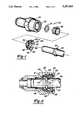
- FIG. 1is an assembly view of a connector according to the present invention.
- FIG. 2is a cross-sectional view through the assembled connector.
- FIG. 3is an end view of the connector prior to tube insertion.
- FIG. 4is a perspective view of the inventive retainer.
- FIG. 1is an exploded view of a connector 20 including conduit or housing 22 defining a bore 23. An axis is defined extending into bore 23. An O-ring 24 and a spacer 26 are inserted axially into the bore. A retainer 28 is inserted into bore 23, and secures a tube 30 within bore 23. Retainer 28 includes a plurality of circumferentially spaced arms 32 which abut a radially greater, or upset portion 34 of tube 30 to retain tube 30 in bore 23.
- Each arm 32includes a radially inner section 33 which abuts upset portion 34.
- a bump 36 formed from a radially inner face of radially inner section 33provides a relatively great force resisting tube insertion, as will be explained below.
- Braces 38extend circumferentially from each circumferential side of radially inner sections 33, and provide additional strength against buckling of retainer 28.
- radially inner section 33includes a lip 40 which abuts upset portion 34. Lip 40 is bent radially outwardly such that it contacts upset portion 34 over a relatively great surface area.
- a rear bend 42connects radially inner section 33 with a radially outer section 43.
- a cylindrical forward ring 44extends axially from a ring 41 which connects the plurality of circumferentially spaced arms 32. Ring 44 provides guidance for tube 30 in bore 23, and extends into a frustoconical bore in spacer 26. As shown, rear bend 42 abuts an inner face 45 of housing 22 to position retainer 28 in bore 23.
- Braces 38extend circumferentially from radially inner sections 33.
- Each bump 36consists of an axially outer ramped portion 47 extending radially outwardly and axially inwardly from the radially inner surface of radially inner section 33.
- a flat or planar portion 48merges with outer ramped portion 47, and is generally parallel to the remainder of radially inner section 33.
- An inner ramped portion 49extends from planar portion 48 back to the radially inner surface of radially inner section 33.
- Outer ramped portion 47applies the sharply increased force. Once upset portion 34 has moved beyond outer ramped portion 47, the momentum of the tube will carry it along planar portion 48, and along inner ramped portion 49 such that tube 30 is fully inserted within conduit 22.
- the radially inner section 33 which secures tube 30 within bore 23may be at an angle which is relatively small compared to the axis of the tube. Bump 36 provides the sharply increased force, while still allowing radially inner section 33 to be at a relatively small angle, where it can provide a strong force against tube removal.
- radially inner sections 33extend for a greater circumferential extent than bumps 36.
- Braces 38extend circumferentially and radially inwardly from each circumferential side of radially inner sections 33.
- Each brace 38has an inner bend 50 bent radially outwardly and back over brace 38.
- Inner bends 50are separate from forward lips 40.
- An outer bend 52is bent radially outwardly and back over brace 38. The included angle between the bends 50 and 52 and braces 48 is acute. Bends 52 and 42 all lie in a single plane, and that plane is used to properly position retainer 28.
- Braces 38are generally parallelogram-like in shape. Bends 50 increase the contact area between retainer 28 and tube upset portion 34 at the axially inner end. It has been found that the bends at the axial ends of the braces not only increase the force necessary to cause buckling of retainer 28, but further ensure that the buckling force is consistent and predictable.
- Radially outer section 43may have openings 54 to decrease the amount of material and further concentrate the strength of retainer 28 at the radially inner section 33.
- retainer 28is stamped from a metal, and more preferably from a stainless steel.
- Planar portion 48preferably extends over a greater axial length than either of the ramped portions 47 and 49. In one embodiment planar portion 48 extended for 1.5 centimeters while the two ramp portions each extended for 0.3 centimeters. In one embodiment the ramped portions extended at a 15° angle from the inner face of radially inner section 33. In an embodiment the angle between bend 50 and brace 38 was 45°, and the angle between bend 52 and brace 3 was 0°-5°.
Landscapes
- Engineering & Computer Science (AREA)
- General Engineering & Computer Science (AREA)
- Mechanical Engineering (AREA)
- Quick-Acting Or Multi-Walled Pipe Joints (AREA)
Abstract
Description
Claims (44)
Priority Applications (6)
| Application Number | Priority Date | Filing Date | Title |
|---|---|---|---|
| US07/766,619US5257833A (en) | 1991-09-25 | 1991-09-25 | Metal retainer for quick connect tubing connector |
| BR919105052ABR9105052A (en) | 1991-09-25 | 1991-11-20 | SEAL TO HOLD A TUBE INSIDE A HOLE; AND FAST TUBE CONNECTOR CONNECTION |
| CA002078173ACA2078173C (en) | 1991-09-25 | 1992-09-14 | Metal retainer for quick connect tubing connector |
| EP92308350AEP0534658A1 (en) | 1991-09-25 | 1992-09-14 | Metal retainer for quick connect tubing connector |
| MX9205450AMX9205450A (en) | 1991-09-25 | 1992-09-24 | METAL RETAINER TO QUICKLY CONNECT A PIPE CONNECTOR. |
| JP4256354AJPH05203088A (en) | 1991-09-25 | 1992-09-25 | Metallic case for fast pipe connector |
Applications Claiming Priority (1)
| Application Number | Priority Date | Filing Date | Title |
|---|---|---|---|
| US07/766,619US5257833A (en) | 1991-09-25 | 1991-09-25 | Metal retainer for quick connect tubing connector |
Publications (1)
| Publication Number | Publication Date |
|---|---|
| US5257833Atrue US5257833A (en) | 1993-11-02 |
Family
ID=25076998
Family Applications (1)
| Application Number | Title | Priority Date | Filing Date |
|---|---|---|---|
| US07/766,619Expired - LifetimeUS5257833A (en) | 1991-09-25 | 1991-09-25 | Metal retainer for quick connect tubing connector |
Country Status (6)
| Country | Link |
|---|---|
| US (1) | US5257833A (en) |
| EP (1) | EP0534658A1 (en) |
| JP (1) | JPH05203088A (en) |
| BR (1) | BR9105052A (en) |
| CA (1) | CA2078173C (en) |
| MX (1) | MX9205450A (en) |
Cited By (27)
| Publication number | Priority date | Publication date | Assignee | Title |
|---|---|---|---|---|
| US5465647A (en)* | 1994-11-14 | 1995-11-14 | Polygon Company | Fluid cylinder end cap assembly |
| US5486025A (en)* | 1994-09-29 | 1996-01-23 | Bundy Corporation | Stuffer pin assembly for quick connector |
| US5651303A (en)* | 1994-11-14 | 1997-07-29 | Polygon Company | Fluid cylinder end cap assembly |
| USD387147S (en)* | 1996-03-21 | 1997-12-02 | Ark Plas Products, Inc. | Plastic luer fitting |
| US5711553A (en)* | 1996-09-04 | 1998-01-27 | Stmc-Llc | Quick connect fluid coupling |
| US5732984A (en)* | 1980-10-29 | 1998-03-31 | Proprietary Technology, Inc. | Manually releasable quick connector |
| US6079750A (en)* | 1996-09-18 | 2000-06-27 | Dana Corporation | Integrated hose body quick connects |
| US6343814B1 (en)* | 1999-11-08 | 2002-02-05 | Ti Group Automotive Systems, Llc | Insertion verifier dust cap |
| US6412826B1 (en)* | 1999-04-16 | 2002-07-02 | Itt Manufacturing Enterprises, Inc. | High pressure quick connector |
| US20050173923A1 (en)* | 2004-02-05 | 2005-08-11 | Ti Group Automotive Systems | Quick connector for high pressure applications |
| US20050258646A1 (en)* | 2004-02-05 | 2005-11-24 | Gunderson Stephen H | Quick connector |
| US20060066101A1 (en)* | 2004-09-29 | 2006-03-30 | Hollnagel Harold E | High pressure line connector |
| US20060202475A1 (en)* | 2005-03-01 | 2006-09-14 | Ti Group Automotive Systems, Llc | Anti-rotation quick connector |
| US20070020973A1 (en)* | 2005-07-20 | 2007-01-25 | Ims Connector Systems Gmbh | Connector plug and mating plug |
| US20070138791A1 (en)* | 2005-12-14 | 2007-06-21 | Greenberger Dorothy G | Stamped collet for push-to-connect tube fittings |
| US20080084064A1 (en)* | 2006-10-06 | 2008-04-10 | Ti Group Automotive Systems, Llc | Quick connector coupling |
| US20080090445A1 (en)* | 2006-10-13 | 2008-04-17 | Luzbetak Mark A | Tube connector |
| US20080231044A1 (en)* | 2007-03-20 | 2008-09-25 | Ti Group Automotive Systems, Llc | Quick Connector for High Pressure Applications |
| KR20090122140A (en)* | 2008-05-23 | 2009-11-26 | 티아이 그룹 오토모티브 시스템즈 엘엘씨 | High Pressure Quick Connector |
| US20100052315A1 (en)* | 2008-08-28 | 2010-03-04 | Ti Group Automotive Systems, Llc | Quick connector coupling with lateral stabilization |
| US20100066075A1 (en)* | 2007-05-25 | 2010-03-18 | Crompton David B | Removal tool and method for push-fit fluid flow systems |
| CN101116228B (en)* | 2005-02-11 | 2011-09-07 | 温彻斯特电子公司 | Snap lock connector |
| US8662540B2 (en) | 2011-11-02 | 2014-03-04 | Philip C. Whitener | Quick tube connector |
| US9816652B2 (en)* | 2013-04-17 | 2017-11-14 | A. Raymond Et Cie | Lock for a tubular connection |
| US20170363240A1 (en)* | 2014-03-28 | 2017-12-21 | Eldon James Corp. | Releasable Valved Coupler |
| US20230383879A1 (en)* | 2022-05-24 | 2023-11-30 | RB Distribution, Inc. | Double sided connector |
| US20240209971A1 (en)* | 2021-07-28 | 2024-06-27 | Oetiker Ny, Inc. | Fluid connection assembly |
Families Citing this family (4)
| Publication number | Priority date | Publication date | Assignee | Title |
|---|---|---|---|---|
| EP0742401A3 (en)* | 1995-05-08 | 1998-05-27 | Proprietary Technology, Inc. | Manually releasable quick connector |
| US5730475A (en)* | 1995-10-13 | 1998-03-24 | Form Rite | Quick connect fluid coupling with collet retainer |
| DE29900796U1 (en) | 1998-04-03 | 1999-04-08 | Geberit Technik Ag, Jona | Device for connecting a pipe socket, tubular fitting or fittings to a pipe |
| JP4573853B2 (en)* | 2007-04-23 | 2010-11-04 | 株式会社アルファ | Push button cylinder lock |
Citations (14)
| Publication number | Priority date | Publication date | Assignee | Title |
|---|---|---|---|---|
| US4541658A (en)* | 1982-03-22 | 1985-09-17 | Proprietary Technology, Inc. | Swivelable quick connector assembly |
| US4681351A (en)* | 1982-03-22 | 1987-07-21 | Proprietary Technology, Inc. | Swivelable quick connector assembly |
| US4756558A (en)* | 1987-06-25 | 1988-07-12 | General Motors Corporation | Quick connect tube coupling |
| US4778203A (en)* | 1982-03-22 | 1988-10-18 | Proprietary Technology, Inc. | Swivelable quick connector for high temperature connection |
| US4846506A (en)* | 1987-09-04 | 1989-07-11 | U.S. Plastics Corporation | Quick connect coupling |
| US4927185A (en)* | 1989-03-07 | 1990-05-22 | Huron Products Corporation | Release tool for fluid quick connectors |
| US4979765A (en)* | 1980-10-29 | 1990-12-25 | Proprietary Technology, Inc. | Swivelable quick connector assembly |
| US5002315A (en)* | 1988-04-07 | 1991-03-26 | Proprietary Technology, Inc. | Quick connector |
| US5009454A (en)* | 1980-10-29 | 1991-04-23 | Proprietary Technology, Inc. | Swivelable quick connector assembly |
| WO1991011651A1 (en)* | 1990-01-16 | 1991-08-08 | Proprietary Technology, Inc. | Snap and lock quick connector |
| US5039139A (en)* | 1990-01-25 | 1991-08-13 | Ford Motor Company | Tube spring steel tab lock coupling connector and method for connecting telescoping tubes |
| US5100182A (en)* | 1990-09-20 | 1992-03-31 | U.S. Plastics Corporation | Fluid connector |
| US5139228A (en)* | 1990-05-10 | 1992-08-18 | Huron Products, Inc. | Fluid connector |
| US5161834A (en)* | 1990-09-27 | 1992-11-10 | Huron Products, Inc. | Fluid connector with cartridge member and release mechanism |
- 1991
- 1991-09-25USUS07/766,619patent/US5257833A/ennot_activeExpired - Lifetime
- 1991-11-20BRBR919105052Apatent/BR9105052A/ennot_activeIP Right Cessation
- 1992
- 1992-09-14EPEP92308350Apatent/EP0534658A1/ennot_activeWithdrawn
- 1992-09-14CACA002078173Apatent/CA2078173C/ennot_activeExpired - Fee Related
- 1992-09-24MXMX9205450Apatent/MX9205450A/ennot_activeIP Right Cessation
- 1992-09-25JPJP4256354Apatent/JPH05203088A/enactivePending
Patent Citations (14)
| Publication number | Priority date | Publication date | Assignee | Title |
|---|---|---|---|---|
| US4979765A (en)* | 1980-10-29 | 1990-12-25 | Proprietary Technology, Inc. | Swivelable quick connector assembly |
| US5009454A (en)* | 1980-10-29 | 1991-04-23 | Proprietary Technology, Inc. | Swivelable quick connector assembly |
| US4778203A (en)* | 1982-03-22 | 1988-10-18 | Proprietary Technology, Inc. | Swivelable quick connector for high temperature connection |
| US4541658A (en)* | 1982-03-22 | 1985-09-17 | Proprietary Technology, Inc. | Swivelable quick connector assembly |
| US4681351A (en)* | 1982-03-22 | 1987-07-21 | Proprietary Technology, Inc. | Swivelable quick connector assembly |
| US4756558A (en)* | 1987-06-25 | 1988-07-12 | General Motors Corporation | Quick connect tube coupling |
| US4846506A (en)* | 1987-09-04 | 1989-07-11 | U.S. Plastics Corporation | Quick connect coupling |
| US5002315A (en)* | 1988-04-07 | 1991-03-26 | Proprietary Technology, Inc. | Quick connector |
| US4927185A (en)* | 1989-03-07 | 1990-05-22 | Huron Products Corporation | Release tool for fluid quick connectors |
| WO1991011651A1 (en)* | 1990-01-16 | 1991-08-08 | Proprietary Technology, Inc. | Snap and lock quick connector |
| US5039139A (en)* | 1990-01-25 | 1991-08-13 | Ford Motor Company | Tube spring steel tab lock coupling connector and method for connecting telescoping tubes |
| US5139228A (en)* | 1990-05-10 | 1992-08-18 | Huron Products, Inc. | Fluid connector |
| US5100182A (en)* | 1990-09-20 | 1992-03-31 | U.S. Plastics Corporation | Fluid connector |
| US5161834A (en)* | 1990-09-27 | 1992-11-10 | Huron Products, Inc. | Fluid connector with cartridge member and release mechanism |
Cited By (46)
| Publication number | Priority date | Publication date | Assignee | Title |
|---|---|---|---|---|
| US5732984A (en)* | 1980-10-29 | 1998-03-31 | Proprietary Technology, Inc. | Manually releasable quick connector |
| US5782508A (en)* | 1980-10-29 | 1998-07-21 | Proprietary Technologies, Inc. | Swivelable quick connector assembly |
| US5964484A (en)* | 1980-10-29 | 1999-10-12 | Proprietary Technology, Inc. | Swivelable quick connector assembly |
| US5992903A (en)* | 1980-10-29 | 1999-11-30 | Proprietary Technology, Inc. | Swivelable quick connector assembly |
| US5486025A (en)* | 1994-09-29 | 1996-01-23 | Bundy Corporation | Stuffer pin assembly for quick connector |
| US5465647A (en)* | 1994-11-14 | 1995-11-14 | Polygon Company | Fluid cylinder end cap assembly |
| US5651303A (en)* | 1994-11-14 | 1997-07-29 | Polygon Company | Fluid cylinder end cap assembly |
| US5669284A (en)* | 1994-11-14 | 1997-09-23 | Polygon Company | Fluid cylinder end cap assembly |
| USD387147S (en)* | 1996-03-21 | 1997-12-02 | Ark Plas Products, Inc. | Plastic luer fitting |
| US5711553A (en)* | 1996-09-04 | 1998-01-27 | Stmc-Llc | Quick connect fluid coupling |
| US6079750A (en)* | 1996-09-18 | 2000-06-27 | Dana Corporation | Integrated hose body quick connects |
| US6412826B1 (en)* | 1999-04-16 | 2002-07-02 | Itt Manufacturing Enterprises, Inc. | High pressure quick connector |
| US6343814B1 (en)* | 1999-11-08 | 2002-02-05 | Ti Group Automotive Systems, Llc | Insertion verifier dust cap |
| US7344166B2 (en) | 2004-02-05 | 2008-03-18 | Ti Group Automotive Systems, Llc | Quick connector for high pressure applications |
| US20050173923A1 (en)* | 2004-02-05 | 2005-08-11 | Ti Group Automotive Systems | Quick connector for high pressure applications |
| US20050258646A1 (en)* | 2004-02-05 | 2005-11-24 | Gunderson Stephen H | Quick connector |
| US20090071562A1 (en)* | 2004-02-05 | 2009-03-19 | Ti Group Automotive Systems, Llc | Quick connector |
| US7467813B2 (en) | 2004-02-05 | 2008-12-23 | Ti Group Automotive Systems, Llc | Quick connector |
| US7891380B2 (en) | 2004-02-05 | 2011-02-22 | Ti Group Automotive Systems, Llc | Protective cap for quick connector |
| US20060066101A1 (en)* | 2004-09-29 | 2006-03-30 | Hollnagel Harold E | High pressure line connector |
| CN101116228B (en)* | 2005-02-11 | 2011-09-07 | 温彻斯特电子公司 | Snap lock connector |
| US7967342B2 (en) | 2005-03-01 | 2011-06-28 | Ti Group Automotive Systems, Llc | Anti-rotation quick connector |
| US20060202475A1 (en)* | 2005-03-01 | 2006-09-14 | Ti Group Automotive Systems, Llc | Anti-rotation quick connector |
| US7238047B2 (en)* | 2005-07-20 | 2007-07-03 | Ims Connector Systems Gmbh | Connector plug and mating plug |
| US20070020973A1 (en)* | 2005-07-20 | 2007-01-25 | Ims Connector Systems Gmbh | Connector plug and mating plug |
| US7850208B2 (en)* | 2005-12-14 | 2010-12-14 | Parker-Hannifin Corporation | Stamped collet for push-to-connect tube fittings |
| US20070138791A1 (en)* | 2005-12-14 | 2007-06-21 | Greenberger Dorothy G | Stamped collet for push-to-connect tube fittings |
| US7731245B2 (en) | 2006-10-06 | 2010-06-08 | Ti Group Automotive Systems, Llc | Quick connector coupling |
| US20080084064A1 (en)* | 2006-10-06 | 2008-04-10 | Ti Group Automotive Systems, Llc | Quick connector coupling |
| EP1909016A3 (en)* | 2006-10-06 | 2008-05-28 | TI Group Automotive Systems, L.L.C. | Quick connector coupling |
| US7780201B2 (en) | 2006-10-13 | 2010-08-24 | Medela Holding Ag | Tube connector with three part construction and latching component |
| US8096824B2 (en) | 2006-10-13 | 2012-01-17 | Medela Holding Ag | Tube connector with a latching component to secure a receptacle to a plug |
| US20100289259A1 (en)* | 2006-10-13 | 2010-11-18 | Medela Ag | Tube Connector with Three Part Construction and Latching Component |
| US20080090445A1 (en)* | 2006-10-13 | 2008-04-17 | Luzbetak Mark A | Tube connector |
| US20080231044A1 (en)* | 2007-03-20 | 2008-09-25 | Ti Group Automotive Systems, Llc | Quick Connector for High Pressure Applications |
| US8939470B2 (en) | 2007-03-20 | 2015-01-27 | Stephen H. Gunderson | Quick connector for high pressure applications |
| US20100066075A1 (en)* | 2007-05-25 | 2010-03-18 | Crompton David B | Removal tool and method for push-fit fluid flow systems |
| KR20090122140A (en)* | 2008-05-23 | 2009-11-26 | 티아이 그룹 오토모티브 시스템즈 엘엘씨 | High Pressure Quick Connector |
| US20100052315A1 (en)* | 2008-08-28 | 2010-03-04 | Ti Group Automotive Systems, Llc | Quick connector coupling with lateral stabilization |
| US8662540B2 (en) | 2011-11-02 | 2014-03-04 | Philip C. Whitener | Quick tube connector |
| US9816652B2 (en)* | 2013-04-17 | 2017-11-14 | A. Raymond Et Cie | Lock for a tubular connection |
| US20170363240A1 (en)* | 2014-03-28 | 2017-12-21 | Eldon James Corp. | Releasable Valved Coupler |
| US10267445B2 (en)* | 2014-03-28 | 2019-04-23 | Craig Alan Ira | Releasable valved coupler |
| US20240209971A1 (en)* | 2021-07-28 | 2024-06-27 | Oetiker Ny, Inc. | Fluid connection assembly |
| US12305785B2 (en)* | 2021-07-28 | 2025-05-20 | Oetiker Ny, Inc. | Fluid connection assembly |
| US20230383879A1 (en)* | 2022-05-24 | 2023-11-30 | RB Distribution, Inc. | Double sided connector |
Also Published As
| Publication number | Publication date |
|---|---|
| EP0534658A1 (en) | 1993-03-31 |
| CA2078173A1 (en) | 1993-03-26 |
| CA2078173C (en) | 1999-07-20 |
| JPH05203088A (en) | 1993-08-10 |
| BR9105052A (en) | 1993-04-20 |
| MX9205450A (en) | 1993-07-01 |
Similar Documents
| Publication | Publication Date | Title |
|---|---|---|
| US5257833A (en) | Metal retainer for quick connect tubing connector | |
| US5228728A (en) | Tube retainer release sleeve | |
| US6676171B2 (en) | Insertion verifier dust cap | |
| EP0667943B1 (en) | Positive transition quick connect coupling | |
| EP0537906A1 (en) | Plastic retainer for fluid coupling | |
| EP0532242B1 (en) | Quick connect tubing connector | |
| US4541657A (en) | Quick release hose coupling | |
| US5542716A (en) | Quick connector with snap-on retainer | |
| US7850208B2 (en) | Stamped collet for push-to-connect tube fittings | |
| US5730475A (en) | Quick connect fluid coupling with collet retainer | |
| US11131411B2 (en) | Fluid connection device | |
| US8113548B2 (en) | Quick connector for high pressure applications | |
| US4671540A (en) | Coupling | |
| EP0728980A1 (en) | Fluid quick connector | |
| US5423577A (en) | Tubing connector | |
| US5303963A (en) | Tube coupling with secondary retainer clip | |
| JPH05196184A (en) | Quick connection coupling by positive movement | |
| US7445249B2 (en) | Coupling | |
| WO1997048937A1 (en) | Snap-action pipe coupling retainer | |
| HK74589A (en) | Tubing joint | |
| US3938833A (en) | Universal pipe joint construction | |
| US5431454A (en) | Quick connection | |
| JP2007514108A (en) | Device for coupling to the end of a corrugated tube | |
| WO1993015349A1 (en) | Tubing connector | |
| US20050104367A1 (en) | Attachment ring for a tube-connecting device |
Legal Events
| Date | Code | Title | Description |
|---|---|---|---|
| AS | Assignment | Owner name:HURON PRODUCTS INDUSTRIES INC., MICHIGAN Free format text:ASSIGNMENT OF ASSIGNORS INTEREST.;ASSIGNORS:MC NAUGHTON, JAMES;WALKER, DONALD C.;REEL/FRAME:005855/0967 Effective date:19910924 | |
| AS | Assignment | Owner name:BUNDY CORPORATION, MICHIGAN Free format text:MERGER;ASSIGNORS:HURON PRODUCTS INDUSTRIES, INC.;HURO PRODUCTS, INC.;REEL/FRAME:006562/0528;SIGNING DATES FROM 19910709 TO 19930331 | |
| STCF | Information on status: patent grant | Free format text:PATENTED CASE | |
| FEPP | Fee payment procedure | Free format text:PAYOR NUMBER ASSIGNED (ORIGINAL EVENT CODE: ASPN); ENTITY STATUS OF PATENT OWNER: LARGE ENTITY | |
| FPAY | Fee payment | Year of fee payment:4 | |
| AS | Assignment | Owner name:TI GROUP AUTOMOTIVE SYSTEMS CORPORATION, MICHIGAN Free format text:CHANGE OF NAME;ASSIGNOR:BUNDY CORPORATION;REEL/FRAME:010859/0541 Effective date:19991012 | |
| FEPP | Fee payment procedure | Free format text:PAYER NUMBER DE-ASSIGNED (ORIGINAL EVENT CODE: RMPN); ENTITY STATUS OF PATENT OWNER: LARGE ENTITY Free format text:PAYOR NUMBER ASSIGNED (ORIGINAL EVENT CODE: ASPN); ENTITY STATUS OF PATENT OWNER: LARGE ENTITY | |
| FPAY | Fee payment | Year of fee payment:8 | |
| AS | Assignment | Owner name:TI GROUP AUTOMOTIVE SYSTEMS, LLC, MICHIGAN Free format text:MERGER;ASSIGNOR:TI GROUP AUTOMOTIVE SYSTEMS CORPORATION;REEL/FRAME:012407/0436 Effective date:20010625 | |
| FPAY | Fee payment | Year of fee payment:12 | |
| AS | Assignment | Owner name:JPMORGAN CHASE BANK, N.A., NEW YORK Free format text:SECURITY AGREEMENT;ASSIGNORS:HANIL USA, L.L.C.;TI AUTOMOTIVE, L.L.C.;TI GROUP AUTOMOTIVE SYSTEMS, L.L.C.;REEL/FRAME:019733/0933 Effective date:20070629 Owner name:JPMORGAN CHASE BANK, N.A.,NEW YORK Free format text:SECURITY AGREEMENT;ASSIGNORS:HANIL USA, L.L.C.;TI AUTOMOTIVE, L.L.C.;TI GROUP AUTOMOTIVE SYSTEMS, L.L.C.;REEL/FRAME:019733/0933 Effective date:20070629 | |
| AS | Assignment | Owner name:WILMINGTON TRUST (LONDON) LIMITED,UNITED KINGDOM Free format text:ASSIGNMENT OF SECURITY INTEREST;ASSIGNOR:JP MORGAN CHASE BANK, N.A.;REEL/FRAME:024055/0633 Effective date:20100208 Owner name:WILMINGTON TRUST (LONDON) LIMITED, UNITED KINGDOM Free format text:ASSIGNMENT OF SECURITY INTEREST;ASSIGNOR:JP MORGAN CHASE BANK, N.A.;REEL/FRAME:024055/0633 Effective date:20100208 | |
| AS | Assignment | Owner name:TI GROUP AUTOMOTIVE SYSTEMS, L.L.C., MICHIGAN Free format text:RELEASE AND TERMINATION OF PATENT SECURITY INTEREST;ASSIGNOR:WILMINGTON TRUST (LONDON) LIMITED (AS SUCCESSOR IN INTEREST TO JP MORGAN CHASE BANK, N.A.);REEL/FRAME:024891/0671 Effective date:20100825 Owner name:CITIBANK N.A., DELAWARE Free format text:ABL PATENT SECURITY AGREEMENT;ASSIGNOR:TI GROUP AUTOMOTIVE SYSTEMS, L.L.C.;REEL/FRAME:024895/0956 Effective date:20100825 Owner name:CITIBANK N.A., DELAWARE Free format text:TERM PATENT SECURITY AGREEMENT;ASSIGNOR:TI GROUP AUTOMOTIVE SYSTEMS, L.L.C.;REEL/FRAME:024896/0057 Effective date:20100825 Owner name:HANIL USA, L.L.C., MICHIGAN Free format text:RELEASE AND TERMINATION OF PATENT SECURITY INTEREST;ASSIGNOR:WILMINGTON TRUST (LONDON) LIMITED (AS SUCCESSOR IN INTEREST TO JP MORGAN CHASE BANK, N.A.);REEL/FRAME:024891/0671 Effective date:20100825 Owner name:TI AUTOMOTIVE, L.L.C., MICHIGAN Free format text:RELEASE AND TERMINATION OF PATENT SECURITY INTEREST;ASSIGNOR:WILMINGTON TRUST (LONDON) LIMITED (AS SUCCESSOR IN INTEREST TO JP MORGAN CHASE BANK, N.A.);REEL/FRAME:024891/0671 Effective date:20100825 | |
| AS | Assignment | Owner name:TI GROUP AUTOMOTIVE SYSTEMS, L.L.C., MICHIGAN Free format text:RELEASE BY SECURED PARTY;ASSIGNOR:CITIBANK, N.A.;REEL/FRAME:027865/0016 Effective date:20120314 |