US5257628A - Ultrasound internal examination system - Google Patents
Ultrasound internal examination systemDownload PDFInfo
- Publication number
- US5257628A US5257628AUS07/910,508US91050892AUS5257628AUS 5257628 AUS5257628 AUS 5257628AUS 91050892 AUS91050892 AUS 91050892AUS 5257628 AUS5257628 AUS 5257628A
- Authority
- US
- United States
- Prior art keywords
- ultrasound
- linear
- radial
- scan
- ultrasound transducer
- Prior art date
- Legal status (The legal status is an assumption and is not a legal conclusion. Google has not performed a legal analysis and makes no representation as to the accuracy of the status listed.)
- Expired - Lifetime
Links
Images


Classifications
- A—HUMAN NECESSITIES
- A61—MEDICAL OR VETERINARY SCIENCE; HYGIENE
- A61B—DIAGNOSIS; SURGERY; IDENTIFICATION
- A61B8/00—Diagnosis using ultrasonic, sonic or infrasonic waves
- A61B8/12—Diagnosis using ultrasonic, sonic or infrasonic waves in body cavities or body tracts, e.g. by using catheters
- A—HUMAN NECESSITIES
- A61—MEDICAL OR VETERINARY SCIENCE; HYGIENE
- A61B—DIAGNOSIS; SURGERY; IDENTIFICATION
- A61B8/00—Diagnosis using ultrasonic, sonic or infrasonic waves
- A61B8/42—Details of probe positioning or probe attachment to the patient
- A61B8/4209—Details of probe positioning or probe attachment to the patient by using holders, e.g. positioning frames
- A—HUMAN NECESSITIES
- A61—MEDICAL OR VETERINARY SCIENCE; HYGIENE
- A61B—DIAGNOSIS; SURGERY; IDENTIFICATION
- A61B8/00—Diagnosis using ultrasonic, sonic or infrasonic waves
- A61B8/44—Constructional features of the ultrasonic, sonic or infrasonic diagnostic device
- A61B8/4444—Constructional features of the ultrasonic, sonic or infrasonic diagnostic device related to the probe
- A61B8/445—Details of catheter construction
- A—HUMAN NECESSITIES
- A61—MEDICAL OR VETERINARY SCIENCE; HYGIENE
- A61B—DIAGNOSIS; SURGERY; IDENTIFICATION
- A61B8/00—Diagnosis using ultrasonic, sonic or infrasonic waves
- A61B8/44—Constructional features of the ultrasonic, sonic or infrasonic diagnostic device
- A61B8/4444—Constructional features of the ultrasonic, sonic or infrasonic diagnostic device related to the probe
- A61B8/4461—Features of the scanning mechanism, e.g. for moving the transducer within the housing of the probe
Definitions
- This inventionrelates to an ultrasound internal examination system having an ultrasound probe to be endoscopically inserted into an intracavitary portion of human body or the like for ultrasound examination.
- ultrasound internal examination systemsare largely constituted by an ultrasound probe with an ultrasound transducer element for transmission and reception of ultrasound signals, a signal processor which has the function of controlling the transmission and reception of the ultrasound signals in addition to the function of processing received echo signals, and a monitor for displaying ultrasound images.
- a signal processorwhich has the function of controlling the transmission and reception of the ultrasound signals in addition to the function of processing received echo signals
- a monitor for displaying ultrasound imagesThere has been known in the art the so-called insert type ultrasound probe which is designed to be introduced into an intracavitary portion of interest, directly or through a guide means such as an endoscope or the like, and to transmit ultrasound pulses into tissues of an intracavitary portion or wall while receiving reflected echo signals.
- the scan modes of ultrasound examination systemsincludes the so-called B mode scan in which ultrasound pulses are transmitted into an intracavitary wall portion at predetermined time intervals from an ultrasound transducer which is being moved over a predetermined scan range, and, on the basis of return echoes, an ultrasound image of the scan range is displayed on a monitor screen.
- B mode scanin which ultrasound pulses are transmitted into an intracavitary wall portion at predetermined time intervals from an ultrasound transducer which is being moved over a predetermined scan range, and, on the basis of return echoes, an ultrasound image of the scan range is displayed on a monitor screen.
- a mechanical scan system or an electronic scan systemis usually employed.
- An insert type ultrasound probe of an extremely small diameterwhich is intended to be inserted through a biopsy channel of an endoscope like forceps, is known, for example, from U.S. Pat. No. 4,802,487.
- the ultrasound probe of this sortthere have been strong demands for further reductions in diameter and length of rigid portions on the probe, and therefore there has been no choice but to employ a single-element ultrasound transducer of small size, instead of an arrangement involving a large number of transducers as in the electronic scan system. It follows that the ultrasound probe of this type is necessarily arranged to operate with a mechanical scan system.
- the ultrasound transducerWith regard to its scanning direction, it can be put in a radial scan in which the ultrasound transducer is turned about an axis or in a linear scan in which the ultrasound transducer is moved linearly.
- the scan rangemay extend to 360° or may be restricted to an arc of a predetermined angle.
- the ultrasound examination systemis usually resorted to in checking for the existence of a tumor or other diseased portion which normally has a certain degree of three-dimensional spreading, so that it is important to grasp the condition of an affected portion three-dimensionally before giving any diagnosis.
- a single-element ultrasound transducercan give only one tomographic ultrasound image in one direction of an intracavitary portion no matter whether it is in radial scan or in linear scan.
- attemptshave been made to get a three-dimensional image of a diseased portion from a plural number of tomographic images which are taken through an ultrasound transducer at a number of different positions. For example, in a radial scanning operation, ultrasound tomographic images are sequentially taken while moving an ultrasound transducer gradually in the linear direction.
- an object of the present inventionto provide an ultrasound internal examination system which can produce ultrasound images in such a way as to permit three-dimensional examination of a diseased portion or the like by the use of simple means.
- an ultrasound internal examination systemwhich essentially includes: an ultrasound probe having a rotatable ultrasound transducer element mounted at the tip end of a flexible cable for movement in radial and linear directions; an operating unit having remote control means for the ultrasound transducer element, including a rotating means, a linearly reciprocating means, a rotational angle sensor means, and a linear position sensor means; and a signal processing means adapted to produce at least an ultrasound tomographic image of radial scan direction or an ultrasound tomographic image of linear scan direction on the basis of ultrasound echo signals from the ultrasound transducer element and signals from the rotational angle sensor means and the linear position sensor means, and arranged to display at least one of ultrasound tomographic images of radial and linear scan directions along with an indicator giving a sign of the position or angular direction of the ultrasound transducer element in the other scan direction.
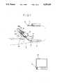
- FIG. 1is a schematic view of an ultrasound examination system in a first embodiment of the invention, showing its general arrangement
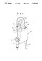
- FIG. 2is a longitudinal sectional view of an ultrasound probe
- FIG. 3is a schematic outer view of an operating unit operatively mounted on an endoscope
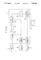
- FIG. 4is a schematic sectional view of the operating unit
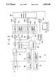
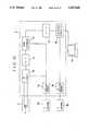
- FIG. 5is a circuit diagram of an ultrasound signal processor
- FIG. 6is a diagrammatic view of a display mode on a monitor screen
- FIG. 7is a diagrammatic view of another display mode in a modified second embodiment of the invention.
- FIG. 8is a circuit diagram of an ultrasound signal processor for the display mode of FIG. 7;
- FIG. 9is a diagrammatic view of a display mode on a monitor screen in another modified third embodiment of the invention.
- FIG. 10is a circuit diagram of an ultrasound signal processor for the display mode of FIG. 8;
- FIG. 11is a schematic outer view of an operating unit in a further embodiment of the invention.
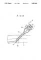
- FIG. 12is a schematic view explanatory of the arrangement of a trocar.
- FIGS. 1 through 6there is shown an ultrasound internal examination system in a first embodiment of the invention, employing an ultrasound probe to be inserted through a biopsy channel C which is provided on an endoscope S for insertion of instruments like forceps.
- FIG. 1shows the general arrangement of the ultrasound examination system, where indicated at 1 is an ultrasound probe having a rigid portion 3 at the tip end of a flexible cable 2 of resilient material and having a single-element ultrasound transducer 4 mounted on the rigid tip end portion 3 which is rotatable relative to the flexible cable 2.
- the ultrasound transducer element 4has its active face 4a disposed in an opening which is formed at one side of the rigid tip end portion 3 for transmission and reception of signals therethrough.
- the flexible cable 2which is to be inserted through a biopsy channel C of the endoscope S and which also serves as a control cable, is formed in a diameter small enough for insertion into the biopsy channel C and, as shown in FIG. 2, has, within a flexible sleeve 2a of a soft friction-free material like fluorine resin, a rotation transmitting member 2b in the form of coil springs which are fitted in the sleeve 2a in superposed or parallel relation with each other. Accordingly, the flexible cable 2 has a function of rotationally driving the ultrasound transducer element 4 on the rigid tip end portion 3 through remote control. Further, a signal transmission/reception line 5 which is in the form of a coaxial cable is passed through the rotation transmitting member 2b in the flexible cable 2.
- the fore end of the rotation transmitting member 2bis fixedly connected to the rigid tip end portion 3 to transmit thereto the momentum of the rotating efforts for the ultrasound transducer element 4.
- the signal line 5is also rotated integrally with the rotation transmitting member 2b to prevent twisting of the line.
- the ultrasound probe 1is provided with a connector 6 at its proximal end for detachably coupling the probe 1 with the operating unit 10.
- the connector 6is constituted by an electrode pin 6a and a cylindrical split socket 6b to which the proximal end of the rotation transmitting member 2b is fixedly connected.
- a wire 5a of the signal line 5is connected to the electrode pin 6a, while another wire 5b of the signal line 5 is connected to the split socket 6b.
- This split socket 6bis formed of a conductive material and separated from the electrode pin 6a by an interposed insulating member 6c.
- a protective sleeve 7 of a more rigid material than that of the sleeve 2a of the flexible cable 2is fitted on the latter over a certain length which is led out of the biopsy channel C of the endoscope S.
- the operating unit 10is detachably fixable on the entrance opening CE of the biopsy channel C of the endoscope S, and is arranged as shown in FIGS. 3 and 4. More specifically, the operating unit 10 is provided with a mount portion 12 on its casing 11, the mount portion 12 being provided with a mount piece 8 for coupling and uncoupling engagement with the entrance opening CE of the biopsy channel C of the endoscope S.
- the mount piece 8has a function as an adaptor which permits to mount the operating unit 10 on endoscopes of different types.
- the mount piece 8 and mount portion 12are formed with holes 8a and 12a, respectively, for threading therethrough the flexible cable 2 of the ultrasound probe 1.
- the connector 13is constituted by a rotary member 14 and a rotary connector 15.
- one end of the rotary member 14is slightly protruded on the outer side of the casing 11.
- the rotary member 14has functions as a rotational shaft which rotationally drives the ultrasound transducer element 4, in addition to functions as a signal transmitting member.
- the rotary member 14includes a core portion 14a which functions as one terminal to be connected to the electrode pin 6a of the connector 6, and an outer sleeve 14b which functions as the other terminal to be connected to the coupling socket 6b.
- An insulation layer 14cis interposed between the core portion 14a and outer sleeve 14b of the rotary member 14.
- the rotary member 14has a rigid rod-like shape as a whole.
- the rotary connector 15is coupled with the rotary member 14 rotatably relative to each other, and provided with an electrode 15a, which is electrically connected to the core portion 14a of the rotary member 14 through a fluid contact 17a consisting of a conductive fluid like mercury, and an electrode 15b which is electrically connected to the outer sleeve 14b through a fluid contact 17b.
- An insulating member 16is interposed between the two electrodes 15a and 15b. Accordingly, through the above-described connector 6, rotary member 14 and rotary connector 15, the signal transfer line 5 which is rotatable with the ultrasound transducer element 4 is connected to a transfer line 19 in an unrotatable cable 18 which is connected to the ultrasound image observation terminal T.
- the ultrasound probe 1can be operated to make a radial scan in which the ultrasound transducer element 4 is turned in the radial direction, and a linear scan in which the transducer element 4 is moved linearly along the rigid tip portion.
- the ultrasound transducer element 4is associated with a radial scan mechanism which is arranged in the manner as follows.
- the rotary member 14is rotatably supported by bearings 20 at the opposite ends thereof.
- a pair of pulleys 21 and 22are mounted side by side on the rotary member 14 between the bearings 20. These pulleys 21 and 22 are connected to output shaft 25a of a rotational drive motor 25 and input shaft 26a of an encoder 26 through belts 23 and 24, respectively.
- Wires 25b and 26b from the motor 25 and encoder 26are passed through the cable 18 which is connected to the ultrasound image observation terminal T.
- a rotation blocking member 27is attached to the protective sleeve 7 in order to prevent the sleeve 2a and protective sleeve 7, which are fitted around the rotation transmitting member 2b, from being twisted upon turning the rotation transmitting member 2b.
- This rotation blocking member 27is detachably fixed to a guide sleeve 11a which is provided on the casing 11 for guiding an operating rod 30 as will be described hereinlater.
- the operating unit 10further includes a linear scan mechanism for pulling the flexible cable 2 back and forth to scan the ultrasound transducer element 4 linearly over a predetermined range.
- the linear scan mechanismincludes an operating rod 30 which serves as a probe operating means and which is mounted on the casing 11 slidably in the axial direction.
- the operating rod 30is provided with a finger holder ring 30a at its outer end which is protruded out of the guide sleeve 11a on the casing 11.
- Extended sideward from a protruded end portion of the operating rod 30is a connecting member 31 which releasably grips a proximal end portion of the flexible cable 2 covered with the protective tube 7 and threaded through the holes 8a and 12a in the mount piece 8 and mount portion 12.
- the flexible cable 2is looped over a certain length between the point where it is gripped by the connecting member 13 and the connector 6 at its proximal end which is disengageably coupled with the operating unit 10.
- the linear position sensor mechanismincludes a rack 32 which is formed on an inner surface of the casing 11, a pinion 33 in meshing engagement with the rack 32, and an encoder 34 coupled with a rotational shaft 33a of the pinion 33.
- the output signal of the encoder 34which is indicative of the position of the operating rod 30, is fed to the ultrasound image observation terminal T as a position signal.
- the operating rod 30is constantly urged outward by a return spring 35 into a protruded position where a stopper 30b on the operating rod 30 is abutted against a guide member 36, which is provided within the casing 11, and can be pushed into the casing 11 against the biasing force of the return spring 35.
- An optical sensor 37is located at the inward stroke end of the operating rod 30 to detect its location at the inward stroke end in cooperation with a light blocking plate 30c which is fixed on the inner end of the operating rod 30.
- the linear scan range of the ultrasound transducer element 4corresponds to the stroke range of the operating rod 30 between the inner end position where the optical sensor 37 is intercepted by the light-blocking plate 30c and the outer position where the stopper 30b is abutted against the guide member 36.
- the inner stroke end position which is detected by the optical sensor 37is taken as a reference position in determining an end position of the ultrasound image to be displayed on the monitor M.
- the reference position signal from the optical sensor 37 and the output signal of the encoder 34are transferred to the ultrasound image observation terminal T through wires 37a and 34a in the cable 18.
- the ultrasound examination systemis capable of producing ultrasound tomographic picture images in two perpendicularly intersecting directions, namely, radial ultrasound images and linear ultrasound images. More specifically, as seen in FIG. 5, the ultrasound transducer elements 4 is driven to transmit ultrasound pulses toward an intracorporeal portion of interest and receive the reflected return echoes, by signals from a transmission/reception (TR) circuit 40. The received echo signals are converted into digital signals through A/D converter 41, and stored in memory 42a of a radial scan converter 42 and also in memory 43a of a linear scan converter 43.
- the resulting analog signalsare transferred to the monitor M through a signal output circuit 45 to display side by side thereon bi-plane picture images of two perpendicularly intersecting directions, namely, a radial ultrasound picture image RP and a linear ultrasound picture image.
- the signal processoris further provided with a radial/linear sequencer 46 for the purpose of controlling the ultrasound pulse transmission/reception by the TR circuit 40 and at the same time for the purpose of supplying control signals to memory controllers 42b and 43 which control the memories 42a and 43a of the radial and linear scan converters 42 and 43, respectively.
- This radial/linear sequencer 46is supplied with a radial angle signal from a radial angle detector circuit 47 which detects the position in the radial direction of the ultrasound transducer element 4 on the basis of signals from the encoder 26, and also with a linear position signal from a linear position detector circuit 48 which detects the position in the linear direction of the ultrasound transducer element 4 on the basis of signals from the encoder 34.
- a linear scan direction setter 49is connected to the radial/linear sequencer 46.
- the linear scan direction setter 49serves to specify the scanning direction of the linear ultrasound picture image LP to be displayed on the monitor M.
- a volume(not shown) may be provided on the operating unit 10, so that the operator can manually enter a signal as to which one of the lines of radial directions should be sampled for the linear ultrasound picture image.
- the radial/linear sequencer 46operates a switch which is inserted in a stage anterior to the memory 43a of the linear scan converter 43, thereby selectively sampling the signals in the specified angular position alone.
- a radial range setter 51is connected to the radial/linear sequencer 46.
- This radial range setter 51serves to delimit the sampling angle of the radial ultrasound picture image RP to a particular range of interest.
- the radial/linear sequencer 46operates a switch 52 which is inserted in a stage anterior to the memory 42a of the radial scan converter 42 to supply the memory 42a with return signals in the specified angular range alone.
- a radial ultrasound picture image RP and a linear ultrasound picture image LPare simultaneously displayed on the monitor M.
- the bi-plane picture image consisting of the radial and linear ultrasound images RP and Lis displayed together with radial and linear indicators RI and LI, respectively.
- the radial indicator RI which is associated with a radial ultrasound picture image RPindicates the direction or angular position of the radial ultrasound picture image which is currently on display
- the linear indicator LI which is associated with a linear ultrasound picture image LPindicates the position of the ultrasound transducer element 4, namely, the position of the displayed radial ultrasound picture image RP in the linear direction.
- the directional or positional signs of the radial and linear indicators RI and LIare obtained by detecting the direction and position of the ultrasound transducer element 4 by the radial/linear sequencer 46 on the basis of signals from the linear direction setter 49 and linear position sensor circuit 48 and supplying the resulting directional and positional signals to the signal output circuit 45 through D/A converter 44c to combine them with the radial and linear ultrasound picture images, showing the directional and positional signs preferably in a graphically depicted form in association with the corresponding ultrasound picture image.
- the above-described radial scan type ultrasound internal examination systemoperates in the manner as follows.
- the endoscope Sis inserted into the patient's body until its tip end reaches an intracorporeal portion to be examined for diagnostic or other purposes.
- the flexible cable 2 of the ultrasound probe 1is inserted into a biopsy channel C of the endoscope S, letting the rigid portion 3 at the tip end of the flexible cable 2 protrude from the fore end of the biopsy channel C over a predetermined length, and then the mount portion 12 on the casing 11 of the operating unit 10 is fixedly joined to the entrance opening CE of the biopsy channel C through the mount piece 8.
- the connector 6 at the terminal end of the flexible cable 2is coupled with the connector 13 on the operating unit 10.
- the motor 25is actuated to put the rotary member 14 in rotation, which rotation is transmitted to the ultrasound transducer element 4 through the rotation transmitting member 2b.
- the operating rod 30is pushed in fully to the end position of its inward stroke, the turning ultrasound transducer element 4 is displaced to a position corresponding to an initial point of its linear stroke.
- the location of the ultrasound transducer element 4 at the inner stroke end positionis detected by the optical sensor 37 in cooperation with the light blocking plate 30c. This position is taken as an initial position of linear scan by the ultrasound transducer element 4.
- the echo signals which are received by the ultrasound transducer element 4 during this outward strokeare sequentially transferred to the TR circuit 40.
- all of the received echo signalsare forwarded to the memory 42a of the radial scan converter 42, and ultrasound tomographic images are sequentially displayed on the monitor M as a radial ultrasound picture image RP one after another in step with the revolution of the ultrasound transducer element 4.
- the echo signals from the direction specified by the linear direction setter 47are sequentially fed to the memory 43a of the linear scan converter 43 from the TR circuit 40.
- a linear ultrasound picture image LP and a radial ultrasound picture image RPare displayed on the monitor M in the bi-plane mode.
- the simultaneous display of ultrasound tomographic images of two perpendicularly intersecting directionsmakes it possible to grasp the condition of intracavitary wall tissues three-dimensionally when checking or identifying a disease.
- the radial ultrasound image RPis totally renewed on every revolution of the ultrasound transducer element 4 and therefore is displayed as a motion picture
- the linear ultrasound image LPis displayed as a still picture which is incrementally added with a new section of picture image as the ultrasound transducer element 4 comes to a next phase of linear scan by a displacement in the axial direction.
- the operatorcan easily confirm the position of such doubtful portion with reference to the indicators LI and RI.
- the doubtful portioncan be examined in a concentrated manner by narrowing the scanning pitch of the ultrasound transducer element 4.
- the linear direction setter 47may be operated to change the sampling direction in each reciprocating movement to obtain linear ultrasound images of a particular locality in sequentially shifted angular positions along with a radial ultrasound image which is renewed at predetermined time intervals. This permits to grasp the condition of a diseased portion three-dimensionally, and provides necessary data for synthesizing a three-dimensional image of the diseased portion by suitable three-dimensional signal processing.
- a location in the linear direction in connection with a radial ultrasound image obtained by the radial scanningmay only need to spot a location in the radial direction in connection with a linear ultrasound image obtained by the linear scanning.
- it is possible to build up a three-dimensional image of a diseased portionif one can obtain radial ultrasound images which are sampled correctly and uniformly at intervals of a predetermined pitch width.
- a three-dimensional image of a diseased portioncan be built up on the basis of linear ultrasound images which are sampled at a plural number of angularly shifted positions.
- the signal processor of the ultrasound image observation terminal Tmay employ a circuitry as shown in FIG. 8.
- the echo signals of ultrasound pulseswhich are transmitted into an intracavitary portion from the ultrasound transducer element 4 according to signals from TR circuit 60, are converted into digital signals through A/D converter 61 and stored in the memory of a scan converter 62.
- This scan converter 62corresponds to the radial scan converter 42 in the above-described first embodiment of the invention, but this circuitry does not include components corresponding to the linear scan converter 43 and radial/linear sequencer 46.
- these ultrasound picture dataare read out from the scan converter 61 and converted into analog signals through D/A converter 63 to display an ultrasound picture image on the monitor M.
- the ultrasound pulseis shot off at predetermined angular intervals in each revolution of the ultrasound transducer element 4.
- a position signal indicative of the rotational angular position of the ultrasound transducer element 4is supplied to a radial position detector circuit 64 from the radial encoder 26.
- the output signal of the radial position detector circuit 64is supplied to TR circuit 60 and scan converter 62.
- the linear encoder 34As the operating rod 30 on the operating unit 10 is manipulated to shift the position of the ultrasound transducer element 4 linearly, the location of the transducer element 4 is constantly monitored by the linear encoder 34.
- the output signal of the linear encoder 34is supplied to a linear position detector circuit 65, and the resulting data on the linear position are combined with the data of a radial ultrasound picture image at a signal output circuit 66 to display the linear position as a linear indicator LI on the monitor M along with the ultrasound picture image.
- FIG. 9there is shown another embodiment employing a modified display mode, in which a linear ultrasound picture image LP resulting from linear scanning of the ultrasound transducer element 4 is displayed on the monitor M along with a radial indicator RI which indicates the angular direction of the linear scanning.
- the signal processor of the ultrasound image observation terminal Tis preferably arranged as shown in FIG. 10.
- the electric motor 25 or a similar drive means for turning the ultrasound transducer element 4 in the radial directionit is necessary to provide the rotary member 14 and the rotary connector 15 as rotating means.
- the coupling socket 6b of the connector 6is fitted on the rotary member 14 in such a way that the operator can manually turn the coupling socket 6b to rotate the ultrasound transducer element 4 to a desired direction.
- drive signalsare applied to the ultrasound transducer element 4 from a TR circuit 70 in the same manner as in the foregoing embodiments, and the return echo signals received by the TR circuit 70 are converted into digital signals through A/D converter 72 and damped into the memory of a scan converter 72.
- the scan converter 72corresponds to the scan converter 43 of the first embodiment, but this circuitry does not include the radial scan converter 42 and radial/linear sequencer 46.
- Each time one frame of ultrasound image data are fed to the scan converter 72these data are read out from the scan converter 72 and converted into analog signals through D/A converter 73 to display a linear ultrasound picture image LP on the monitor M.
- the output signal of the linear encoder 34is fed to the linear position detector circuit 74, the output signal of which detector circuit 74 being applied to the TR circuit 70 as a transmission trigger signal and also to the scan converter 72 as an address signal for the image display.
- the position in the radial direction of the ultrasound transducer element 4is displayed on the monitor M by the use of the output signal of the radial encoder 26, which is indicative of the rotational angular position of the ultrasound transducer element 4.
- the output signal of the radial encoder 26is applied to the radial position detector circuit 75 thereby to determine the position of the ultrasound transducer element 4 in the radial direction.
- This signal of the radial position of the ultrasound transducer element 4is forwarded to the signal output circuit 76 and combined with the linear ultrasound image signal which is concurrently transferred to the signal output circuit 76 through D/A converter 73, to display on the monitor M a linear ultrasound picture image along with a radial indicator RI giving the data on the radial or angular position of the ultrasound transducer element 4.
- the axial position or the radial or angular direction of the ultrasound transducer element 4is displayed by the linear or radial indicator LI or RI along with a radial or linear ultrasound picture image while scanning the transducer element 4 in the radial or linear direction, so that the operator can immediately recognize the current position or direction of the transducer element 4 on the screen.
- Thisis very convenient because, after taking a radial or linear ultrasound tomographic image, the ultrasound transducer element 4 can be quickly relocated in a next position of examination.
- the position or direction of the ultrasound transducer element 4can be varied accurately with reference to the linear indicator LI or radial indicator RI to obtain ultrasound picture images with accuracy which is required in a closer examination of the diseased portion.
- the ultrasound transducer element 4is largely displaced from one position to another for successive scanning operations at two different positions, it can be easily relocated in the first position easily in an accurate manner.
- the records of the ultrasound examinationswhich contain the positional or directional information along with the ultrasound picture images, also contribute to improve the quality of examinations.
- a plural number of ultrasound tomographic imagesare sampled at certain angular intervals, it becomes possible to synthesize a three-dimensional image of a diseased portion or the like from the sampled data after suitable three-dimensional image processing.
- FIGS. 11 and 12there is shown a fourth embodiment of the invention, employing an ultrasound probe 1 which is arranged to be inserted into a blood vessel.
- a blood vessel Vitself is utilized as a guide for the ultrasound probe 1.
- a trocar 80is employed for the purpose of introducing the ultrasound probe 1 into the blood vessel V.
- the trocar 80is provided with a mount portion 83 of a larger diameter at the proximal end of a cylindrical body 80 to be attached to the operating unit 10, and sharp-pointed at its fore end for piercing the blood vessel wall.
- the ultrasound probe 1 and operating unit 10are arranged substantially in the same manner as in the above-described first embodiment, and therefore the description and illustration of details of these components are omitted here to avoid unnecessary repetitions.
- radial and linear ultrasound data of tissues of the blood vessel Vcan be simultaneously sampled along the length thereof, and displayed on the monitor M as a bi-plane ultrasound picture image, permitting the operator to grasp the condition of a particular locality under examination three-dimensionally and accurately, for example, when checking for the position or the degree of obliteration of the blood vessel V.
Landscapes
- Life Sciences & Earth Sciences (AREA)
- Health & Medical Sciences (AREA)
- Biomedical Technology (AREA)
- Biophysics (AREA)
- Nuclear Medicine, Radiotherapy & Molecular Imaging (AREA)
- Pathology (AREA)
- Radiology & Medical Imaging (AREA)
- Engineering & Computer Science (AREA)
- Physics & Mathematics (AREA)
- Heart & Thoracic Surgery (AREA)
- Medical Informatics (AREA)
- Molecular Biology (AREA)
- Surgery (AREA)
- Animal Behavior & Ethology (AREA)
- General Health & Medical Sciences (AREA)
- Public Health (AREA)
- Veterinary Medicine (AREA)
- Ultra Sonic Daignosis Equipment (AREA)
Abstract
Description
Claims (5)
Applications Claiming Priority (6)
| Application Number | Priority Date | Filing Date | Title |
|---|---|---|---|
| JP3-196120 | 1991-07-11 | ||
| JP3-196121 | 1991-07-11 | ||
| JP3196120AJP2712908B2 (en) | 1991-07-11 | 1991-07-11 | Radial scanning ultrasonic inspection system |
| JP3196123AJP2658645B2 (en) | 1991-07-11 | 1991-07-11 | Linear scanning ultrasonic inspection system |
| JP3196121AJPH0515538A (en) | 1991-07-11 | 1991-07-11 | Byplane type ultrasonic inspection instrument |
| JP3-196123 | 1991-07-11 |
Publications (1)
| Publication Number | Publication Date |
|---|---|
| US5257628Atrue US5257628A (en) | 1993-11-02 |
Family
ID=27327191
Family Applications (1)
| Application Number | Title | Priority Date | Filing Date |
|---|---|---|---|
| US07/910,508Expired - LifetimeUS5257628A (en) | 1991-07-11 | 1992-07-08 | Ultrasound internal examination system |
Country Status (1)
| Country | Link |
|---|---|
| US (1) | US5257628A (en) |
Cited By (46)
| Publication number | Priority date | Publication date | Assignee | Title |
|---|---|---|---|---|
| DE4412243C1 (en)* | 1994-04-05 | 1995-07-13 | Arno Schnorrenberg | Intestinal ultrasound probe for trans-intestinal diagnosis in birds, reptiles and small mammals |
| US5469852A (en)* | 1993-03-12 | 1995-11-28 | Kabushiki Kaisha Toshiba | Ultrasound diagnosis apparatus and probe therefor |
| US5486170A (en)* | 1992-10-26 | 1996-01-23 | Ultrasonic Sensing And Monitoring Systems | Medical catheter using optical fibers that transmit both laser energy and ultrasonic imaging signals |
| US5494040A (en)* | 1993-08-25 | 1996-02-27 | Fujitsu Limited | Ultrasonic diagnosis device with bright position-indicating line |
| US5497776A (en)* | 1993-08-05 | 1996-03-12 | Olympus Optical Co., Ltd. | Ultrasonic image diagnosing apparatus for displaying three-dimensional image |
| US5680865A (en)* | 1994-10-20 | 1997-10-28 | Fuji Photo Optical Co., Ltd. | Dual ultrasound probe |
| US5792059A (en)* | 1996-11-26 | 1998-08-11 | Esaote S.P.A. | Intraoperative probe, specifically intended for direct-contact observations |
| EP0776178A4 (en)* | 1994-07-20 | 1998-11-11 | Boston Scient Corp | Medical acoustic imaging |
| US5916210A (en)* | 1990-01-26 | 1999-06-29 | Intraluminal Therapeutics, Inc. | Catheter for laser treatment of atherosclerotic plaque and other tissue abnormalities |
| US6027450A (en)* | 1994-12-30 | 2000-02-22 | Devices For Vascular Intervention | Treating a totally or near totally occluded lumen |
| US6230568B1 (en) | 1992-02-07 | 2001-05-15 | Ultrasonic Sensing And Monitoring Systems, Inc. | Method and apparatus for ultrasonic inspection of inaccessible areas |
| US6379302B1 (en) | 1999-10-28 | 2002-04-30 | Surgical Navigation Technologies Inc. | Navigation information overlay onto ultrasound imagery |
| US6461304B1 (en) | 1999-03-30 | 2002-10-08 | Fuji Photo Optical Co., Ltd. | Ultrasound inspection apparatus detachably connected to endoscope |
| US20030220561A1 (en)* | 2002-03-11 | 2003-11-27 | Estelle Camus | Method and apparatus for acquiring and displaying a medical instrument introduced into a cavity organ of a patient to be examined or treated |
| WO2003011138A3 (en)* | 2001-07-26 | 2004-03-11 | Ludlow Co Lp | High speed electronic remote medical imaging system and method |
| US7241263B2 (en) | 2004-09-30 | 2007-07-10 | Scimed Life Systems, Inc. | Selectively rotatable shaft coupler |
| US7413543B2 (en) | 2003-04-01 | 2008-08-19 | Scimed Life Systems, Inc. | Endoscope with actively cooled illumination sources |
| US7479106B2 (en) | 2004-09-30 | 2009-01-20 | Boston Scientific Scimed, Inc. | Automated control of irrigation and aspiration in a single-use endoscope |
| US7578786B2 (en) | 2003-04-01 | 2009-08-25 | Boston Scientific Scimed, Inc. | Video endoscope |
| US7591783B2 (en) | 2003-04-01 | 2009-09-22 | Boston Scientific Scimed, Inc. | Articulation joint for video endoscope |
| US7597662B2 (en) | 2004-09-30 | 2009-10-06 | Boston Scientific Scimed, Inc. | Multi-fluid delivery system |
| US20100274085A1 (en)* | 2007-12-28 | 2010-10-28 | John Mugan | Exchangeable guide-wire with balloon for foreign body extraction |
| US7846107B2 (en) | 2005-05-13 | 2010-12-07 | Boston Scientific Scimed, Inc. | Endoscopic apparatus with integrated multiple biopsy device |
| US7955255B2 (en) | 2006-04-20 | 2011-06-07 | Boston Scientific Scimed, Inc. | Imaging assembly with transparent distal cap |
| US7967759B2 (en) | 2006-01-19 | 2011-06-28 | Boston Scientific Scimed, Inc. | Endoscopic system with integrated patient respiratory status indicator |
| US20110190662A1 (en)* | 2008-10-01 | 2011-08-04 | Beacon Endoscopic Corporation | Rapid exchange fna biopsy device with diagnostic and therapeutic capabilities |
| US8052597B2 (en) | 2005-08-30 | 2011-11-08 | Boston Scientific Scimed, Inc. | Method for forming an endoscope articulation joint |
| US8083671B2 (en) | 2004-09-30 | 2011-12-27 | Boston Scientific Scimed, Inc. | Fluid delivery system for use with an endoscope |
| US8097003B2 (en) | 2005-05-13 | 2012-01-17 | Boston Scientific Scimed, Inc. | Endoscopic apparatus with integrated variceal ligation device |
| US8118732B2 (en) | 2003-04-01 | 2012-02-21 | Boston Scientific Scimed, Inc. | Force feedback control system for video endoscope |
| US8199187B2 (en) | 2004-09-30 | 2012-06-12 | Boston Scientific Scimed, Inc. | Adapter for use with digital imaging medical device |
| US8202265B2 (en) | 2006-04-20 | 2012-06-19 | Boston Scientific Scimed, Inc. | Multiple lumen assembly for use in endoscopes or other medical devices |
| US8353860B2 (en) | 2004-09-30 | 2013-01-15 | Boston Scientific Scimed, Inc. | Device for obstruction removal with specific tip structure |
| US8357148B2 (en) | 2004-09-30 | 2013-01-22 | Boston Scientific Scimed, Inc. | Multi-functional endoscopic system for use in electrosurgical applications |
| US8535219B2 (en) | 2003-04-01 | 2013-09-17 | Boston Scientific Scimed, Inc. | Fluid manifold for endoscope system |
| US8888684B2 (en) | 2006-03-27 | 2014-11-18 | Boston Scientific Scimed, Inc. | Medical devices with local drug delivery capabilities |
| US8968210B2 (en) | 2008-10-01 | 2015-03-03 | Covidien LLP | Device for needle biopsy with integrated needle protection |
| US9186128B2 (en) | 2008-10-01 | 2015-11-17 | Covidien Lp | Needle biopsy device |
| US9332973B2 (en) | 2008-10-01 | 2016-05-10 | Covidien Lp | Needle biopsy device with exchangeable needle and integrated needle protection |
| US9782565B2 (en) | 2008-10-01 | 2017-10-10 | Covidien Lp | Endoscopic ultrasound-guided biliary access system |
| JP2018099259A (en)* | 2016-12-20 | 2018-06-28 | 富士フイルム株式会社 | Ultrasonic probe |
| CN110893106A (en)* | 2019-12-29 | 2020-03-20 | 俞德芳 | High-frequency single-vibration-element linear array scanning two-dimensional imaging B-ultrasonic probe |
| US11298113B2 (en) | 2008-10-01 | 2022-04-12 | Covidien Lp | Device for needle biopsy with integrated needle protection |
| US11419483B2 (en)* | 2018-04-12 | 2022-08-23 | Endosound, Inc. | Steerable ultrasound attachment for endoscope |
| US20220378399A1 (en)* | 2021-05-26 | 2022-12-01 | Siemens Medical Solutions Usa, Inc. | Ultrasound probe with adjustable aperture |
| US11759184B2 (en)* | 2017-08-07 | 2023-09-19 | Utah Valley University | Apparatus, system and method for diagnostic imaging forceps |
Citations (4)
| Publication number | Priority date | Publication date | Assignee | Title |
|---|---|---|---|---|
| US5050610A (en)* | 1990-11-14 | 1991-09-24 | Advanced Technology Laboratories, Inc. | Transesophageal ultrasonic scanhead |
| US5099850A (en)* | 1989-01-17 | 1992-03-31 | Olympus Optical Co., Ltd. | Ultrasonic diagnostic apparatus |
| US5107844A (en)* | 1989-04-06 | 1992-04-28 | Olympus Optical Co., Ltd. | Ultrasonic observing apparatus |
| US5131393A (en)* | 1990-06-25 | 1992-07-21 | Fuji Photo Optical Co., Ltd. | Ultrasound internal examination system |
- 1992
- 1992-07-08USUS07/910,508patent/US5257628A/ennot_activeExpired - Lifetime
Patent Citations (4)
| Publication number | Priority date | Publication date | Assignee | Title |
|---|---|---|---|---|
| US5099850A (en)* | 1989-01-17 | 1992-03-31 | Olympus Optical Co., Ltd. | Ultrasonic diagnostic apparatus |
| US5107844A (en)* | 1989-04-06 | 1992-04-28 | Olympus Optical Co., Ltd. | Ultrasonic observing apparatus |
| US5131393A (en)* | 1990-06-25 | 1992-07-21 | Fuji Photo Optical Co., Ltd. | Ultrasound internal examination system |
| US5050610A (en)* | 1990-11-14 | 1991-09-24 | Advanced Technology Laboratories, Inc. | Transesophageal ultrasonic scanhead |
Cited By (75)
| Publication number | Priority date | Publication date | Assignee | Title |
|---|---|---|---|---|
| US5916210A (en)* | 1990-01-26 | 1999-06-29 | Intraluminal Therapeutics, Inc. | Catheter for laser treatment of atherosclerotic plaque and other tissue abnormalities |
| US6230568B1 (en) | 1992-02-07 | 2001-05-15 | Ultrasonic Sensing And Monitoring Systems, Inc. | Method and apparatus for ultrasonic inspection of inaccessible areas |
| US5486170A (en)* | 1992-10-26 | 1996-01-23 | Ultrasonic Sensing And Monitoring Systems | Medical catheter using optical fibers that transmit both laser energy and ultrasonic imaging signals |
| US5469852A (en)* | 1993-03-12 | 1995-11-28 | Kabushiki Kaisha Toshiba | Ultrasound diagnosis apparatus and probe therefor |
| US5497776A (en)* | 1993-08-05 | 1996-03-12 | Olympus Optical Co., Ltd. | Ultrasonic image diagnosing apparatus for displaying three-dimensional image |
| US5494040A (en)* | 1993-08-25 | 1996-02-27 | Fujitsu Limited | Ultrasonic diagnosis device with bright position-indicating line |
| DE4412243C1 (en)* | 1994-04-05 | 1995-07-13 | Arno Schnorrenberg | Intestinal ultrasound probe for trans-intestinal diagnosis in birds, reptiles and small mammals |
| EP0776178A4 (en)* | 1994-07-20 | 1998-11-11 | Boston Scient Corp | Medical acoustic imaging |
| US5680865A (en)* | 1994-10-20 | 1997-10-28 | Fuji Photo Optical Co., Ltd. | Dual ultrasound probe |
| US6027450A (en)* | 1994-12-30 | 2000-02-22 | Devices For Vascular Intervention | Treating a totally or near totally occluded lumen |
| US5792059A (en)* | 1996-11-26 | 1998-08-11 | Esaote S.P.A. | Intraoperative probe, specifically intended for direct-contact observations |
| US6461304B1 (en) | 1999-03-30 | 2002-10-08 | Fuji Photo Optical Co., Ltd. | Ultrasound inspection apparatus detachably connected to endoscope |
| US6968224B2 (en) | 1999-10-28 | 2005-11-22 | Surgical Navigation Technologies, Inc. | Method of detecting organ matter shift in a patient |
| US6379302B1 (en) | 1999-10-28 | 2002-04-30 | Surgical Navigation Technologies Inc. | Navigation information overlay onto ultrasound imagery |
| US6669635B2 (en) | 1999-10-28 | 2003-12-30 | Surgical Navigation Technologies, Inc. | Navigation information overlay onto ultrasound imagery |
| US20040197058A1 (en)* | 2001-07-26 | 2004-10-07 | Eric Eichelberger | High speed electronic remote medical imaging system and method |
| US6882785B2 (en) | 2001-07-26 | 2005-04-19 | The Ludlow Company Lp | High speed electronic remote medical imaging system and method |
| WO2003011138A3 (en)* | 2001-07-26 | 2004-03-11 | Ludlow Co Lp | High speed electronic remote medical imaging system and method |
| US20030220561A1 (en)* | 2002-03-11 | 2003-11-27 | Estelle Camus | Method and apparatus for acquiring and displaying a medical instrument introduced into a cavity organ of a patient to be examined or treated |
| US6923768B2 (en)* | 2002-03-11 | 2005-08-02 | Siemens Aktiengesellschaft | Method and apparatus for acquiring and displaying a medical instrument introduced into a cavity organ of a patient to be examined or treated |
| US7591783B2 (en) | 2003-04-01 | 2009-09-22 | Boston Scientific Scimed, Inc. | Articulation joint for video endoscope |
| US7413543B2 (en) | 2003-04-01 | 2008-08-19 | Scimed Life Systems, Inc. | Endoscope with actively cooled illumination sources |
| US10765307B2 (en) | 2003-04-01 | 2020-09-08 | Boston Scientific Scimed, Inc. | Endoscopic imaging system |
| US7578786B2 (en) | 2003-04-01 | 2009-08-25 | Boston Scientific Scimed, Inc. | Video endoscope |
| US8118732B2 (en) | 2003-04-01 | 2012-02-21 | Boston Scientific Scimed, Inc. | Force feedback control system for video endoscope |
| US9913573B2 (en) | 2003-04-01 | 2018-03-13 | Boston Scientific Scimed, Inc. | Endoscopic imaging system |
| US8622894B2 (en) | 2003-04-01 | 2014-01-07 | Boston Scientific Scimed, Inc. | Articulation joint |
| US8608648B2 (en) | 2003-04-01 | 2013-12-17 | Boston Scientific Scimed, Inc. | Articulation joint |
| US8535219B2 (en) | 2003-04-01 | 2013-09-17 | Boston Scientific Scimed, Inc. | Fluid manifold for endoscope system |
| US8475366B2 (en) | 2003-04-01 | 2013-07-02 | Boston Scientific Scimed, Inc. | Articulation joint for a medical device |
| US8425408B2 (en) | 2003-04-01 | 2013-04-23 | Boston Scientific Scimed, Inc. | Articulation joint for video endoscope |
| US11324395B2 (en) | 2003-04-01 | 2022-05-10 | Boston Scientific Scimed, Inc. | Endoscopic imaging system |
| US8199187B2 (en) | 2004-09-30 | 2012-06-12 | Boston Scientific Scimed, Inc. | Adapter for use with digital imaging medical device |
| USRE46007E1 (en) | 2004-09-30 | 2016-05-24 | Boston Scientific Scimed, Inc. | Automated control of irrigation and aspiration in a single-use endoscope |
| US8083671B2 (en) | 2004-09-30 | 2011-12-27 | Boston Scientific Scimed, Inc. | Fluid delivery system for use with an endoscope |
| US8197400B2 (en) | 2004-09-30 | 2012-06-12 | Boston Scientific Scimed, Inc. | Selectively rotatable shaft coupler |
| US7597662B2 (en) | 2004-09-30 | 2009-10-06 | Boston Scientific Scimed, Inc. | Multi-fluid delivery system |
| US7479106B2 (en) | 2004-09-30 | 2009-01-20 | Boston Scientific Scimed, Inc. | Automated control of irrigation and aspiration in a single-use endoscope |
| US8353860B2 (en) | 2004-09-30 | 2013-01-15 | Boston Scientific Scimed, Inc. | Device for obstruction removal with specific tip structure |
| US8357148B2 (en) | 2004-09-30 | 2013-01-22 | Boston Scientific Scimed, Inc. | Multi-functional endoscopic system for use in electrosurgical applications |
| US7241263B2 (en) | 2004-09-30 | 2007-07-10 | Scimed Life Systems, Inc. | Selectively rotatable shaft coupler |
| US8435172B2 (en) | 2004-09-30 | 2013-05-07 | Boston Scientific Scimed, Inc. | Automated control of irrigation and aspiration in a single-use endoscope |
| US7846107B2 (en) | 2005-05-13 | 2010-12-07 | Boston Scientific Scimed, Inc. | Endoscopic apparatus with integrated multiple biopsy device |
| US8585715B2 (en) | 2005-05-13 | 2013-11-19 | Boston Scientific Scimed, Inc. | Endoscopic apparatus with integrated variceal ligation device |
| US8097003B2 (en) | 2005-05-13 | 2012-01-17 | Boston Scientific Scimed, Inc. | Endoscopic apparatus with integrated variceal ligation device |
| US11191424B2 (en) | 2005-08-30 | 2021-12-07 | Boston Scientific Scimed, Inc. | Method for forming an endoscope articulation joint |
| US11957312B2 (en) | 2005-08-30 | 2024-04-16 | Boston Scientific Scimed, Inc. | Method for forming an endoscope articulation joint |
| US10052013B2 (en) | 2005-08-30 | 2018-08-21 | Boston Scientific Scimed, Inc. | Medical device comprising segments |
| US8052597B2 (en) | 2005-08-30 | 2011-11-08 | Boston Scientific Scimed, Inc. | Method for forming an endoscope articulation joint |
| US9439557B2 (en) | 2005-08-30 | 2016-09-13 | Boston Scientific Scimed, Inc. | Articulation joint |
| US7967759B2 (en) | 2006-01-19 | 2011-06-28 | Boston Scientific Scimed, Inc. | Endoscopic system with integrated patient respiratory status indicator |
| US8888684B2 (en) | 2006-03-27 | 2014-11-18 | Boston Scientific Scimed, Inc. | Medical devices with local drug delivery capabilities |
| US9358363B2 (en) | 2006-04-20 | 2016-06-07 | Boston Scientific Scimed, Inc. | Multiple lumen assembly for use in endoscopes or other medical devices |
| US8870753B2 (en) | 2006-04-20 | 2014-10-28 | Boston Scientific Scimed, Inc. | Imaging assembly with transparent distal cap |
| US7955255B2 (en) | 2006-04-20 | 2011-06-07 | Boston Scientific Scimed, Inc. | Imaging assembly with transparent distal cap |
| US8202265B2 (en) | 2006-04-20 | 2012-06-19 | Boston Scientific Scimed, Inc. | Multiple lumen assembly for use in endoscopes or other medical devices |
| US20100274085A1 (en)* | 2007-12-28 | 2010-10-28 | John Mugan | Exchangeable guide-wire with balloon for foreign body extraction |
| US8968210B2 (en) | 2008-10-01 | 2015-03-03 | Covidien LLP | Device for needle biopsy with integrated needle protection |
| US9332973B2 (en) | 2008-10-01 | 2016-05-10 | Covidien Lp | Needle biopsy device with exchangeable needle and integrated needle protection |
| US9913630B2 (en) | 2008-10-01 | 2018-03-13 | Covidien Lp | Device for needle biopsy with integrated needle protection |
| US10076316B2 (en) | 2008-10-01 | 2018-09-18 | Covidien Lp | Needle biopsy device |
| US9782565B2 (en) | 2008-10-01 | 2017-10-10 | Covidien Lp | Endoscopic ultrasound-guided biliary access system |
| US20110190662A1 (en)* | 2008-10-01 | 2011-08-04 | Beacon Endoscopic Corporation | Rapid exchange fna biopsy device with diagnostic and therapeutic capabilities |
| US10888689B2 (en) | 2008-10-01 | 2021-01-12 | Covidien Lp | Endoscopic ultrasound-guided biliary access system |
| US11039816B2 (en) | 2008-10-01 | 2021-06-22 | Covidien Lp | Needle biopsy device with exchangeable needle and integrated needle protection |
| US9186128B2 (en) | 2008-10-01 | 2015-11-17 | Covidien Lp | Needle biopsy device |
| US11298113B2 (en) | 2008-10-01 | 2022-04-12 | Covidien Lp | Device for needle biopsy with integrated needle protection |
| JP2018099259A (en)* | 2016-12-20 | 2018-06-28 | 富士フイルム株式会社 | Ultrasonic probe |
| US11759184B2 (en)* | 2017-08-07 | 2023-09-19 | Utah Valley University | Apparatus, system and method for diagnostic imaging forceps |
| US11419483B2 (en)* | 2018-04-12 | 2022-08-23 | Endosound, Inc. | Steerable ultrasound attachment for endoscope |
| US20230218148A1 (en)* | 2018-04-12 | 2023-07-13 | Endosound, Inc. | Steerable ultrasound attachment for endoscope |
| US11930999B2 (en) | 2018-04-12 | 2024-03-19 | Endosound, Inc. | Steerable ultrasound attachment for endoscope |
| CN110893106A (en)* | 2019-12-29 | 2020-03-20 | 俞德芳 | High-frequency single-vibration-element linear array scanning two-dimensional imaging B-ultrasonic probe |
| US20220378399A1 (en)* | 2021-05-26 | 2022-12-01 | Siemens Medical Solutions Usa, Inc. | Ultrasound probe with adjustable aperture |
| US11911215B2 (en)* | 2021-05-26 | 2024-02-27 | Siemens Medical Solutions Usa, Inc. | Ultrasound probe with adjustable aperture |
Similar Documents
| Publication | Publication Date | Title |
|---|---|---|
| US5257628A (en) | Ultrasound internal examination system | |
| US5417216A (en) | Mechanical radial scan type ultrasound probe | |
| US5131393A (en) | Ultrasound internal examination system | |
| EP1306054B1 (en) | A device for examining a subject capable of marking a boundary range for the insertion/retraction of a member | |
| US5211176A (en) | Ultrasound examination system | |
| EP0486270B2 (en) | Transesophageal ultrasonic scanhead | |
| US4756313A (en) | Ultrasonic probe | |
| US5199437A (en) | Ultrasonic imager | |
| EP0061332B1 (en) | Combined endoscope and ultrasonic diagnostic device | |
| US5671748A (en) | Ultrasound endoscope having ultrasound probe in combination with endoscopic observation system | |
| US5680865A (en) | Dual ultrasound probe | |
| EP1653861B1 (en) | Automated longitudinal position translator for ultrasonic imaging probes | |
| US5150715A (en) | Ultrasound-imaging diagnostic system | |
| US8211021B2 (en) | Ultrasound image processing apparatus and ultrasound diagnostic apparatus | |
| JP4394226B2 (en) | Endoscope position detection device for endoscope | |
| JPH04200459A (en) | Ultrasonic testing apparatus | |
| JP2658645B2 (en) | Linear scanning ultrasonic inspection system | |
| JPS642727Y2 (en) | ||
| US5494040A (en) | Ultrasonic diagnosis device with bright position-indicating line | |
| JP2712908B2 (en) | Radial scanning ultrasonic inspection system | |
| JP2747000B2 (en) | Ultrasound diagnostic equipment | |
| JP4406133B2 (en) | Endoscope position detection device for endoscope | |
| JP2746022B2 (en) | Probe connection mechanism of ultrasonic inspection equipment | |
| JP2722934B2 (en) | Ultrasonic inspection equipment | |
| JPS6258257B2 (en) |
Legal Events
| Date | Code | Title | Description |
|---|---|---|---|
| AS | Assignment | Owner name:FUJI PHOTO OPTICAL CO., LTD., JAPAN Free format text:ASSIGNMENT OF ASSIGNORS INTEREST.;ASSIGNORS:ISHIGURO, MASAAKI;TOSHIZUMI, TOSHIZUMI;REEL/FRAME:006467/0871 Effective date:19920625 | |
| AS | Assignment | Owner name:FUJI PHOTO OPTICAL CO., LTD., JAPAN Free format text:CORRECTIVE ASSIGNMENT RECORDED ON REEL 6467, FRAME 871.;ASSIGNORS:ISHIGURO, MASAAKI;TANAKA, TOSHIZUMI;REEL/FRAME:006622/0250 Effective date:19920625 | |
| STCF | Information on status: patent grant | Free format text:PATENTED CASE | |
| FPAY | Fee payment | Year of fee payment:4 | |
| FEPP | Fee payment procedure | Free format text:PAYOR NUMBER ASSIGNED (ORIGINAL EVENT CODE: ASPN); ENTITY STATUS OF PATENT OWNER: LARGE ENTITY | |
| FPAY | Fee payment | Year of fee payment:8 | |
| FPAY | Fee payment | Year of fee payment:12 | |
| AS | Assignment | Owner name:FUJINON CORPORATION, JAPAN Free format text:CHANGE OF NAME;ASSIGNOR:FUJI PHOTO OPTICAL CO., LTD.;REEL/FRAME:016712/0700 Effective date:20041001 |