US5257070A - Selective control of distributed drives to maintain interdocument gap during jam recovery purge - Google Patents
Selective control of distributed drives to maintain interdocument gap during jam recovery purgeDownload PDFInfo
- Publication number
- US5257070A US5257070AUS07/941,621US94162192AUS5257070AUS 5257070 AUS5257070 AUS 5257070AUS 94162192 AUS94162192 AUS 94162192AUS 5257070 AUS5257070 AUS 5257070A
- Authority
- US
- United States
- Prior art keywords
- copy
- copy sheet
- zones
- sheets
- sheet
- Prior art date
- Legal status (The legal status is an assumption and is not a legal conclusion. Google has not performed a legal analysis and makes no representation as to the accuracy of the status listed.)
- Expired - Lifetime
Links
- 238000010926purgeMethods0.000titleclaimsabstractdescription26
- 238000011084recoveryMethods0.000titleclaimsdescription18
- 238000000034methodMethods0.000claimsabstractdescription46
- 230000008569processEffects0.000claimsabstractdescription29
- 230000007257malfunctionEffects0.000claimsabstractdescription21
- 230000003213activating effectEffects0.000claimsabstractdescription10
- 230000032258transportEffects0.000description23
- 108091008695photoreceptorsProteins0.000description5
- 239000000843powderSubstances0.000description5
- 238000003384imaging methodMethods0.000description3
- 230000001351cycling effectEffects0.000description2
- 238000012986modificationMethods0.000description2
- 230000004048modificationEffects0.000description2
- 230000004044responseEffects0.000description2
- 230000004913activationEffects0.000description1
- 239000011230binding agentSubstances0.000description1
- 239000003086colorantSubstances0.000description1
- 238000001514detection methodMethods0.000description1
- 230000009977dual effectEffects0.000description1
- 230000002779inactivationEffects0.000description1
- 230000000977initiatory effectEffects0.000description1
- 230000001788irregularEffects0.000description1
- 230000007246mechanismEffects0.000description1
- 238000005192partitionMethods0.000description1
- 230000003134recirculating effectEffects0.000description1
Images

Classifications
- G—PHYSICS
- G03—PHOTOGRAPHY; CINEMATOGRAPHY; ANALOGOUS TECHNIQUES USING WAVES OTHER THAN OPTICAL WAVES; ELECTROGRAPHY; HOLOGRAPHY
- G03G—ELECTROGRAPHY; ELECTROPHOTOGRAPHY; MAGNETOGRAPHY
- G03G15/00—Apparatus for electrographic processes using a charge pattern
- G03G15/65—Apparatus which relate to the handling of copy material
- G—PHYSICS
- G03—PHOTOGRAPHY; CINEMATOGRAPHY; ANALOGOUS TECHNIQUES USING WAVES OTHER THAN OPTICAL WAVES; ELECTROGRAPHY; HOLOGRAPHY
- G03G—ELECTROGRAPHY; ELECTROPHOTOGRAPHY; MAGNETOGRAPHY
- G03G15/00—Apparatus for electrographic processes using a charge pattern
- G03G15/70—Detecting malfunctions relating to paper handling, e.g. jams
- G—PHYSICS
- G03—PHOTOGRAPHY; CINEMATOGRAPHY; ANALOGOUS TECHNIQUES USING WAVES OTHER THAN OPTICAL WAVES; ELECTROGRAPHY; HOLOGRAPHY
- G03G—ELECTROGRAPHY; ELECTROPHOTOGRAPHY; MAGNETOGRAPHY
- G03G2215/00—Apparatus for electrophotographic processes
- G03G2215/00362—Apparatus for electrophotographic processes relating to the copy medium handling
- G03G2215/00367—The feeding path segment where particular handling of the copy medium occurs, segments being adjacent and non-overlapping. Each segment is identified by the most downstream point in the segment, so that for instance the segment labelled "Fixing device" is referring to the path between the "Transfer device" and the "Fixing device"
- G03G2215/00371—General use over the entire feeding path
- G—PHYSICS
- G03—PHOTOGRAPHY; CINEMATOGRAPHY; ANALOGOUS TECHNIQUES USING WAVES OTHER THAN OPTICAL WAVES; ELECTROGRAPHY; HOLOGRAPHY
- G03G—ELECTROGRAPHY; ELECTROPHOTOGRAPHY; MAGNETOGRAPHY
- G03G2215/00—Apparatus for electrophotographic processes
- G03G2215/00362—Apparatus for electrophotographic processes relating to the copy medium handling
- G03G2215/00535—Stable handling of copy medium
- G03G2215/00548—Jam, error detection, e.g. double feeding
- G03G2215/00552—Purge of recording medium at jam
- G—PHYSICS
- G03—PHOTOGRAPHY; CINEMATOGRAPHY; ANALOGOUS TECHNIQUES USING WAVES OTHER THAN OPTICAL WAVES; ELECTROGRAPHY; HOLOGRAPHY
- G03G—ELECTROGRAPHY; ELECTROPHOTOGRAPHY; MAGNETOGRAPHY
- G03G2215/00—Apparatus for electrophotographic processes
- G03G2215/00362—Apparatus for electrophotographic processes relating to the copy medium handling
- G03G2215/00535—Stable handling of copy medium
- G03G2215/00556—Control of copy medium feeding
Definitions
- the inventionrelates to jam recovery and, more particularly, to a technique for eliminating malfunctions during a jam recovery purge cycle.
- Jam recovery and associated job recovery in many present copiersoften requires the removal of documents and copy sheets stopped in several places in the machine even if the jam occurred in only one location to only one document.
- Jam recoveryalso often requires the manual restacking of the manually reordered document set back in the document handler tray, as well as the removal and throwing away of some or all of copies in process in the machine. This can be a time consuming and inefficient operation.
- Xerox U.S. Pat. No. 4,786,041discloses an improved jam clearance and job recovery system for a recirculating document handler (RDH) for determining whether a jammed document is present in a first, second, or third document path jam zone, each jam zone corresponding to three distributed drive zones.
- the systemautomatically provides a preliminary job recovery operation before the RDH is fully stopped, by correspondingly operating the document feeding zones to feed unjammed documents in the third jam zone to a stacking tray, or to feed unjammed documents in the first jam zone to the platen, so that documents are directed to be operator removed from only one zone.
- the method of purging copy sheets from a copy sheet path having a plurality of zones after a machine malfunctionincluding the steps of determining the existence of copy sheets in process in any of the copy sheet path zones, selectively activating a plurality of independent copy sheet drives to maintain a predetermined interdocument space between any copy sheets in process, and systematically purging the copy sheets from the zones of the paper path in a predetermined order based upon the particular disposition of the copy sheets in the copy sheet path zones.
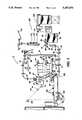
- FIG. 1is a plan view illustrating the principal mechanical components of a typical printing system incorporating the present invention.
- FIG. 2is an expanded view of the copy sheet path of FIG. 1 in accordance with the present invention.
- FIG. 1there is shown an exemplary laser based printing system 2 for processing print jobs in accordance with the teachings of the present invention.
- Printing system 2for purposes of explanation is divided into a controller section and a printer section. While a specific printing system is shown and described, the present invention may be used with other types of printing systems such as ink jet, ionographic, etc.
- the printer sectioncomprises a laser type printer and for purposes of explanation is separated into a Raster Output Scanner (ROS) section, Print Module Section, Paper Supply section, and Finisher.
- the ROShas a laser 91, the beam of which is split into two imaging beams 94.
- Each beam 94is modulated in accordance with the content of an image signal input by acousto-optic modulator 92 to provide dual imaging beams 94.
- Beams 94are scanned across a moving photoreceptor 98 of the Print Module by the mirrored facets of a rotating polygon 100 to expose two image lines on photoreceptor 98 with each scan and create the latent electrostatic images represented by the image signal input to modulator 92.
- Photoreceptor 98is uniformly charged by corotrons 102 at a charging station preparatory to exposure by imaging beams 94.
- the latent electrostatic imagesare developed by developer 104 and transferred at transfer station 106 to print media delivered by the Paper Supply section.
- Print mediamay comprise any of a variety of sheet sizes, types, and colors.
- the print media or copy sheetis brought forward in timed registration with the developed image on photoreceptor 98 from either a main paper tray high capacity feeder 82 or from auxiliary or secondary paper trays 74 or 78.
- a copy sheetis provided via de-skew rollers 71 and copy sheet feed roller 72.
- the photoconductive belt 98is exposed to a pretransfer light from a lamp (not shown) to reduce the attraction between photoconductive belt and the toner powder image.
- a corona generating device 36charges the copy sheet to the proper magnitude and polarity so that the copy sheet is tacked to photoconductive belt and the toner powder image attracted from the photoconductive belt to the copy sheet.
- corona generator 38charges the copy sheet to the opposite polarity to detack the copy sheet from belt.
- fuser assembly 52includes a heated fuser roller 54 and a pressure roller 56 with the powder image on the copy sheet contacting fuser roller 54.
- the copy sheetsare fed through a decurler 58 to remove any curl.
- Forwarding rollers 60then advance the sheet via duplex turn roll 62 to a gate which guides the sheet to output tray 118, finishing station 120 or to duplex inverter 66.
- the duplex inverter 66provides a temporary wait station for each sheet that has been printed on one side and on which an image will be subsequently printed on the opposite side. Each sheet is held in the duplex inverter 66 face down until feed time occurs.
- the simplex sheet in the inverter 66is fed back to the transfer station 106 via conveyor 70, de-skew rollers 71 and paper feed rollers 72 for transfer of the second toner powder image to the opposed sides of the copy sheets.
- the duplex sheetis then fed through the same path as the simplex sheet to be advanced to the finishing station which includes a stitcher and a thermal binder.
- Copy sheetsare supplied from the secondary tray 74 by sheet feeder 76 or from secondary tray 78 by sheet feeder 80.
- Sheet feeders 76, 80are friction retard feeders utilizing a feed belt and take-away rolls to advance successive copy sheets to transport 70 which advances the sheets to rolls 72 and then to the transfer station.
- a high capacity feeder 82is the primary source of copy sheets.
- Tray 84 of feeder 82is supported on an elevator 86 for up and down movement and has a vacuum feed belt 88 to feed successive uppermost sheets from the stack of sheets in tray 84 to a take away drive roll 90 and idler rolls 92.
- Rolls 90, 92guide the sheet onto transport 93 which in cooperation with idler roll 95, de-skew rollers 96 and paper feed rollers 97 move the sheet to the transfer station via de-skew rollers 71 and feed rollers 72.
- Zones 1 and 2illustrate the copy sheet path from the high capacity feeder 82 to de-skew rollers 71
- zone 3illustrates the copy sheet path along conveyor or transport 70
- zone 4illustrates the copy sheet path from the de-skew rollers 71 to the transfer station, 106.
- Zone 5illustrates the copy sheet path between the transfer station and the fuser 52
- zone 6illustrates the copy sheet path from the fuser to decurler 58
- zone 7illustrates the copy sheet path between the decurler 58 and the rollers 60
- zone 8illustrates the copy sheet path from the rollers 60 to the finishing station
- zone 9illustrates the copy sheet path from the duplex invertor 66 to the duplex feed rolls
- zone 10illustrates the copy sheet path between the duplex feed rolls 69 and the top of the conveyor 70.
- partitions of the copy sheet path into ten zonesis arbitrary.
- certain portions of the copy sheet pathare independently driven and are adapted to be selectively turned on or off through the operation of motor, solenoids and clutch mechanisms.
- a suitable clutch 73mechanically connected to the transport or conveyor 70 controls the movement of the conveyor 70 and suitable solenoids 75 operate to selectively engage and disengage the de-skew rollers 71.
- zones 5, 6, 7 and 8are driven by the main drive of the machine, and therefore with the main drive in operation, copy sheets are driven from the transfer station 106 at the photoreceptor 98 to the input to the finishing station 102.
- Zones 1 and 2are driven by the high capacity feeder drive 90, 93 to convey copy sheets from the high capacity feeder to engagement with the de-skew rollers 71 and copy sheets in zone 3 are driven by the transport 70 suitably interconnected to the main drive through the transport clutch 73.
- Copy sheets in zone 4are independently driven by a registration servo motor suitably driving the registration rolls 72 as well as by the operation of a cross roll motor driving de-skew rollers 71 suitably engaged to oppositely disposed idler rolls 71a by the activation and inactivation of solenoid 75. Finally, copy sheets in the duplex tray are driven by duplex drive rolls 69 into engagement with the transport 70.
- the different copy sheet drivesare selectively activated to maintain suitable spacing between copy sheets to be purged.
- the sheets in processare purged in a predetermined order based upon the copy sheet path zones.
- initially all copy sheets in process in zones 5, 6, 7 and 8are immediately purged to an output station or tray while the other copy sheet drives remain inactive.
- the registration rollsare not activated to insure that the sheet at the registration roll is held back to be at the proper spacing with any sheet at the transfer station.
- the registration servo driving rollers 72 and the cross roll or de-skew rollers 71are operated to step copy sheets in process in zones 3 and 4 through the de-skew rollers and registration rollers to zones 5, 6, 7 and 8 with a suitable document gap.
- the procedureUpon clearing zones 3 as well as copy sheets in the duplex tray and zones 9 and 10 through the process, the procedure then switches to any copy sheets in process in zones 1 or 2 being fed by the high capacity feeder. These copy sheets in process are then also stepped through zones 4, 5, 6, 7 and 8 to be purged to an output station.
- the main driveis turned on to purge out sheets left in the paper path down stream (zones 5, 6, 7 and 8) of the registration servo rollers 72. This forces a gap between a sheet in the transfer area and any sheet held in the registration servo rollers 72.
- the registration servo motoris turned on. This will start any sheet in the registration servo rollers 72 moving through the paper path. In turn, this naturally separates any sheet in the registration servo rollers 72 from any other sheets on the registration transport (i.e. in zone 4).
- the remaining sheets on the registration transport or in zone 4must be driven out one at a time. This is done by activating solenoid 75 to disengage rolls 71a from contact with rollers 71 to hold sheets on the vertical transport 70 until the next sheet is detected at the registration servo sensor 79, at which time, the rollers 71 are turned back off. At this point the sheet that arrived at the registration servo sensor 79 is in the servo rollers 72 and will continue to be driven through zones 5, 6, 7, 8 out of the machine. But because the rollers 71 were turned off, any sheets remaining on the registration transport are held. This serves to force a gap between the first sheet on the registration transport and any others on the transport.
- rollers 71are turned back on until the next sheet on the registration transport is brought up to the servo rollers 72. Again, this sheet is allowed to continue on while the other sheets are stopped. This cycle repeats until all sheets are cleared off of the registration transport.
- the vertical transport 70is cleared in a similar manner.
- the solenoid 75is turned off and the vertical transport clutch 73 and the rollers 71 are turned on.
- the vertical transport clutch 73 and the rollers 71are turned off to hold sheets on the registration transport, but the sheet at the registration servo sensor 75 continues on.
- the vertical transport clutch and the rollers 71are turned on again and the next sheet is brought up to registration servo sensor 79. This continues until all of the sheets are cleared off of the vertical registration transport 70.
- the high capacity feeder 82is directed to clear to transport in a similar manner.
Landscapes
- Physics & Mathematics (AREA)
- General Physics & Mathematics (AREA)
- Controlling Sheets Or Webs (AREA)
Abstract
Description
Claims (13)
Priority Applications (1)
| Application Number | Priority Date | Filing Date | Title |
|---|---|---|---|
| US07/941,621US5257070A (en) | 1992-09-08 | 1992-09-08 | Selective control of distributed drives to maintain interdocument gap during jam recovery purge |
Applications Claiming Priority (1)
| Application Number | Priority Date | Filing Date | Title |
|---|---|---|---|
| US07/941,621US5257070A (en) | 1992-09-08 | 1992-09-08 | Selective control of distributed drives to maintain interdocument gap during jam recovery purge |
Publications (1)
| Publication Number | Publication Date |
|---|---|
| US5257070Atrue US5257070A (en) | 1993-10-26 |
Family
ID=25476793
Family Applications (1)
| Application Number | Title | Priority Date | Filing Date |
|---|---|---|---|
| US07/941,621Expired - LifetimeUS5257070A (en) | 1992-09-08 | 1992-09-08 | Selective control of distributed drives to maintain interdocument gap during jam recovery purge |
Country Status (1)
| Country | Link |
|---|---|
| US (1) | US5257070A (en) |
Cited By (19)
| Publication number | Priority date | Publication date | Assignee | Title |
|---|---|---|---|---|
| US5416570A (en)* | 1992-11-27 | 1995-05-16 | Ricoh Company, Ltd. | Image forming apparatus with a vertical transport portion |
| US5459553A (en)* | 1993-05-24 | 1995-10-17 | Samsung Electronics Co., Ltd. | Method for eliminating a paper jam in an image forming system |
| US5461460A (en)* | 1993-05-24 | 1995-10-24 | Samsung Electronics Co., Ltd. | Method for eliminating a paper jam in an image forming system |
| EP0661605A3 (en)* | 1994-01-04 | 1995-12-27 | Xerox Corp | Control for induced jam of selected zone of machine. |
| US5489968A (en)* | 1994-01-04 | 1996-02-06 | Xerox Corporation | Copy sheet purge processing device |
| US5532793A (en)* | 1993-10-21 | 1996-07-02 | Fuji Xerox Co., Ltd. | Paper transport apparatus capable of removing less jammed paper in image forming apparatus |
| US5999758A (en)* | 1998-03-02 | 1999-12-07 | Xerox Corporation | Hybrid hierarchical control architecture for media handling |
| US6011936A (en)* | 1995-05-16 | 2000-01-04 | Canon Kabushiki Kaisha | Image forming apparatus having recovery process for jammed sheets |
| US6010127A (en)* | 1997-04-14 | 2000-01-04 | Xerox Corporation | Internal purge for easy jam clearance in copiers/printers |
| US6322069B1 (en) | 1999-03-12 | 2001-11-27 | Xerox Corporation | Interpaper spacing control in a media handling system |
| EP1275515A3 (en)* | 2001-07-12 | 2003-10-22 | Xerox Corporation | Method and system for purging and preparing a printer |
| US6782822B2 (en)* | 2000-02-23 | 2004-08-31 | Agfa-Gevaert | Compact printing apparatus and method |
| US20040247354A1 (en)* | 2003-06-04 | 2004-12-09 | Newell Lawrence B. | Printing device with media path flushing |
| US20060051141A1 (en)* | 2004-09-09 | 2006-03-09 | Xerox Corporation | Xerographic printer split drive system to reduce image smear |
| EP1642731A1 (en)* | 2000-02-23 | 2006-04-05 | Agfa-Gevaert | Method and apparatus for transporting a receiving substrate in an ink jet printer |
| US20070297816A1 (en)* | 2006-06-26 | 2007-12-27 | Konica Minolta Business Technologies, Inc. | Image forming apparatus and control method thereof |
| US20110187039A1 (en)* | 2010-01-29 | 2011-08-04 | Brother Kogyo Kabushiki Kaisha | Image forming apparatus |
| JP2015036741A (en)* | 2013-08-13 | 2015-02-23 | コニカミノルタ株式会社 | Image forming apparatus, image forming method, and image forming system |
| US12259093B2 (en) | 2020-08-31 | 2025-03-25 | Saudi Arabian Oil Company | Systems and methods for volume fraction analysis of production fluids utilizing a vertically oriented fluidic separation chamber |
Citations (7)
| Publication number | Priority date | Publication date | Assignee | Title |
|---|---|---|---|---|
| US4231567A (en)* | 1978-12-01 | 1980-11-04 | Xerox Corporation | Method and apparatus for clearing jams in copiers |
| US4627711A (en)* | 1985-09-30 | 1986-12-09 | Xerox Corporation | Machine shutdown control |
| US4786041A (en)* | 1987-11-06 | 1988-11-22 | Xerox Corporation | Document handler jam clearance and job recovery system |
| US4878428A (en)* | 1987-08-12 | 1989-11-07 | Fujitsu Limited | Control method of transporting a cut sheet in a printing station and an apparatus using the same |
| US5045881A (en)* | 1990-08-30 | 1991-09-03 | Xerox Corporation | System for segregating purge sheets and continued printing |
| US5086319A (en)* | 1989-11-17 | 1992-02-04 | Xerox Corporation | Multiple servo system for compensation of document mis-registration |
| US5142340A (en)* | 1991-07-15 | 1992-08-25 | Xerox Corporation | Fuser clean-up purge sheets system for duplex reproduction apparatus |
- 1992
- 1992-09-08USUS07/941,621patent/US5257070A/ennot_activeExpired - Lifetime
Patent Citations (7)
| Publication number | Priority date | Publication date | Assignee | Title |
|---|---|---|---|---|
| US4231567A (en)* | 1978-12-01 | 1980-11-04 | Xerox Corporation | Method and apparatus for clearing jams in copiers |
| US4627711A (en)* | 1985-09-30 | 1986-12-09 | Xerox Corporation | Machine shutdown control |
| US4878428A (en)* | 1987-08-12 | 1989-11-07 | Fujitsu Limited | Control method of transporting a cut sheet in a printing station and an apparatus using the same |
| US4786041A (en)* | 1987-11-06 | 1988-11-22 | Xerox Corporation | Document handler jam clearance and job recovery system |
| US5086319A (en)* | 1989-11-17 | 1992-02-04 | Xerox Corporation | Multiple servo system for compensation of document mis-registration |
| US5045881A (en)* | 1990-08-30 | 1991-09-03 | Xerox Corporation | System for segregating purge sheets and continued printing |
| US5142340A (en)* | 1991-07-15 | 1992-08-25 | Xerox Corporation | Fuser clean-up purge sheets system for duplex reproduction apparatus |
Cited By (29)
| Publication number | Priority date | Publication date | Assignee | Title |
|---|---|---|---|---|
| US5416570A (en)* | 1992-11-27 | 1995-05-16 | Ricoh Company, Ltd. | Image forming apparatus with a vertical transport portion |
| US5459553A (en)* | 1993-05-24 | 1995-10-17 | Samsung Electronics Co., Ltd. | Method for eliminating a paper jam in an image forming system |
| US5461460A (en)* | 1993-05-24 | 1995-10-24 | Samsung Electronics Co., Ltd. | Method for eliminating a paper jam in an image forming system |
| US5532793A (en)* | 1993-10-21 | 1996-07-02 | Fuji Xerox Co., Ltd. | Paper transport apparatus capable of removing less jammed paper in image forming apparatus |
| EP0661605A3 (en)* | 1994-01-04 | 1995-12-27 | Xerox Corp | Control for induced jam of selected zone of machine. |
| US5489968A (en)* | 1994-01-04 | 1996-02-06 | Xerox Corporation | Copy sheet purge processing device |
| US6011936A (en)* | 1995-05-16 | 2000-01-04 | Canon Kabushiki Kaisha | Image forming apparatus having recovery process for jammed sheets |
| US6010127A (en)* | 1997-04-14 | 2000-01-04 | Xerox Corporation | Internal purge for easy jam clearance in copiers/printers |
| US5999758A (en)* | 1998-03-02 | 1999-12-07 | Xerox Corporation | Hybrid hierarchical control architecture for media handling |
| US6322069B1 (en) | 1999-03-12 | 2001-11-27 | Xerox Corporation | Interpaper spacing control in a media handling system |
| EP1642731A1 (en)* | 2000-02-23 | 2006-04-05 | Agfa-Gevaert | Method and apparatus for transporting a receiving substrate in an ink jet printer |
| US20060124004A1 (en)* | 2000-02-23 | 2006-06-15 | Verhoest Bart | Method and apparatus for transporting a receiving substrate in an ink jet printer |
| US6782822B2 (en)* | 2000-02-23 | 2004-08-31 | Agfa-Gevaert | Compact printing apparatus and method |
| US20060125901A1 (en)* | 2000-02-23 | 2006-06-15 | Bart Verhoest | Method and apparatus for transporting a receiving substrate in a duplex ink jet printing unit |
| US20050022684A1 (en)* | 2000-02-23 | 2005-02-03 | Verhoest Bart | Compact printing apparatus and method |
| US7032520B2 (en) | 2000-02-23 | 2006-04-25 | Agfa-Gevaert N.V. | Compact printing apparatus and method |
| EP1275515A3 (en)* | 2001-07-12 | 2003-10-22 | Xerox Corporation | Method and system for purging and preparing a printer |
| US9340382B2 (en) | 2003-06-04 | 2016-05-17 | Hewlett-Packard Development Company, L.P. | Printing device with media path flushing |
| US20040247354A1 (en)* | 2003-06-04 | 2004-12-09 | Newell Lawrence B. | Printing device with media path flushing |
| US8379233B2 (en) | 2003-06-04 | 2013-02-19 | Hewlett-Packard Development Company, L.P. | Printing device with media path flushing |
| US20060051141A1 (en)* | 2004-09-09 | 2006-03-09 | Xerox Corporation | Xerographic printer split drive system to reduce image smear |
| US7024143B2 (en) | 2004-09-09 | 2006-04-04 | Xerox Corporation | Xerographic printer split drive system to reduce image smear |
| US20070297816A1 (en)* | 2006-06-26 | 2007-12-27 | Konica Minolta Business Technologies, Inc. | Image forming apparatus and control method thereof |
| US20110187039A1 (en)* | 2010-01-29 | 2011-08-04 | Brother Kogyo Kabushiki Kaisha | Image forming apparatus |
| CN102145827A (en)* | 2010-01-29 | 2011-08-10 | 兄弟工业株式会社 | Image forming apparatus |
| US8302963B2 (en)* | 2010-01-29 | 2012-11-06 | Brother Kogyo Kabushiki Kaisha | Image forming apparatus capable of printing on both sides of sheet |
| CN102145827B (en)* | 2010-01-29 | 2014-07-30 | 兄弟工业株式会社 | Image forming apparatus |
| JP2015036741A (en)* | 2013-08-13 | 2015-02-23 | コニカミノルタ株式会社 | Image forming apparatus, image forming method, and image forming system |
| US12259093B2 (en) | 2020-08-31 | 2025-03-25 | Saudi Arabian Oil Company | Systems and methods for volume fraction analysis of production fluids utilizing a vertically oriented fluidic separation chamber |
Similar Documents
| Publication | Publication Date | Title |
|---|---|---|
| US5257070A (en) | Selective control of distributed drives to maintain interdocument gap during jam recovery purge | |
| EP0620504B1 (en) | Method of recovery from a sheet jam including single zone clearance | |
| JPS6313533B2 (en) | ||
| US6322069B1 (en) | Interpaper spacing control in a media handling system | |
| US5424821A (en) | Control of intermingled copy sheets having different characteristics in paper path | |
| CN101266426A (en) | image forming device | |
| EP0713156B1 (en) | Sheet transport device for a duplex printing system | |
| US5258818A (en) | Photocopier with duplex tray save after jam | |
| US5414495A (en) | Control for induced jam of selected zone of machine | |
| US5058879A (en) | Document production having jam shutdown and clearing strategy | |
| US6082727A (en) | Top vacuum corrugation feeder with active retard separation mechanism | |
| US20100329762A1 (en) | Image forming apparatus | |
| JPH11327220A (en) | Image forming device | |
| JPH05289549A (en) | Image forming device | |
| JP3142169B2 (en) | Transport path switching device | |
| JP2516010Y2 (en) | Cut paper transport device | |
| JP3291799B2 (en) | Image forming device | |
| JP2001242760A (en) | Paper post-processing apparatus, image forming apparatus, and image forming method | |
| JP3120577B2 (en) | Paper transport device for image forming apparatus | |
| JP2638957B2 (en) | Paper reversing device for image forming apparatus | |
| JP2672670B2 (en) | Image forming device | |
| JP2002104697A (en) | Image forming device | |
| JP2003122085A (en) | Image processing device | |
| JPS6270868A (en) | Copy machine control method | |
| JPH0192134A (en) | Method of controlling paper feed in image forming device having intermediate tray |
Legal Events
| Date | Code | Title | Description |
|---|---|---|---|
| AS | Assignment | Owner name:XEROX CORPORATION, CONNECTICUT Free format text:ASSIGNMENT OF ASSIGNORS INTEREST.;ASSIGNORS:MILLER, DONALD L.;BOOTH, RONALD P., SR.;ROSCOE, GARY W.;AND OTHERS;REEL/FRAME:006260/0910 Effective date:19920902 | |
| STCF | Information on status: patent grant | Free format text:PATENTED CASE | |
| FEPP | Fee payment procedure | Free format text:PAYOR NUMBER ASSIGNED (ORIGINAL EVENT CODE: ASPN); ENTITY STATUS OF PATENT OWNER: LARGE ENTITY | |
| FPAY | Fee payment | Year of fee payment:4 | |
| FPAY | Fee payment | Year of fee payment:8 | |
| AS | Assignment | Owner name:BANK ONE, NA, AS ADMINISTRATIVE AGENT, ILLINOIS Free format text:SECURITY INTEREST;ASSIGNOR:XEROX CORPORATION;REEL/FRAME:013153/0001 Effective date:20020621 | |
| AS | Assignment | Owner name:JPMORGAN CHASE BANK, AS COLLATERAL AGENT, TEXAS Free format text:SECURITY AGREEMENT;ASSIGNOR:XEROX CORPORATION;REEL/FRAME:015134/0476 Effective date:20030625 Owner name:JPMORGAN CHASE BANK, AS COLLATERAL AGENT,TEXAS Free format text:SECURITY AGREEMENT;ASSIGNOR:XEROX CORPORATION;REEL/FRAME:015134/0476 Effective date:20030625 | |
| FPAY | Fee payment | Year of fee payment:12 | |
| AS | Assignment | Owner name:XEROX CORPORATION, CONNECTICUT Free format text:RELEASE BY SECURED PARTY;ASSIGNOR:JPMORGAN CHASE BANK, N.A. AS SUCCESSOR-IN-INTEREST ADMINISTRATIVE AGENT AND COLLATERAL AGENT TO JPMORGAN CHASE BANK;REEL/FRAME:066728/0193 Effective date:20220822 |