US5256155A - Drop detection method and apparatus - Google Patents
Drop detection method and apparatusDownload PDFInfo
- Publication number
- US5256155A US5256155AUS07/678,639US67863991AUS5256155AUS 5256155 AUS5256155 AUS 5256155AUS 67863991 AUS67863991 AUS 67863991AUS 5256155 AUS5256155 AUS 5256155A
- Authority
- US
- United States
- Prior art keywords
- drop
- output signal
- detector
- chamber
- light
- Prior art date
- Legal status (The legal status is an assumption and is not a legal conclusion. Google has not performed a legal analysis and makes no representation as to the accuracy of the status listed.)
- Expired - Lifetime
Links
Images


Classifications
- G—PHYSICS
- G02—OPTICS
- G02B—OPTICAL ELEMENTS, SYSTEMS OR APPARATUS
- G02B5/00—Optical elements other than lenses
- G02B5/08—Mirrors
- G02B5/10—Mirrors with curved faces
- A—HUMAN NECESSITIES
- A61—MEDICAL OR VETERINARY SCIENCE; HYGIENE
- A61M—DEVICES FOR INTRODUCING MEDIA INTO, OR ONTO, THE BODY; DEVICES FOR TRANSDUCING BODY MEDIA OR FOR TAKING MEDIA FROM THE BODY; DEVICES FOR PRODUCING OR ENDING SLEEP OR STUPOR
- A61M5/00—Devices for bringing media into the body in a subcutaneous, intra-vascular or intramuscular way; Accessories therefor, e.g. filling or cleaning devices, arm-rests
- A61M5/14—Infusion devices, e.g. infusing by gravity; Blood infusion; Accessories therefor
- A61M5/168—Means for controlling media flow to the body or for metering media to the body, e.g. drip meters, counters ; Monitoring media flow to the body
- A61M5/16886—Means for controlling media flow to the body or for metering media to the body, e.g. drip meters, counters ; Monitoring media flow to the body for measuring fluid flow rate, i.e. flowmeters
- A61M5/1689—Drip counters
- G—PHYSICS
- G01—MEASURING; TESTING
- G01V—GEOPHYSICS; GRAVITATIONAL MEASUREMENTS; DETECTING MASSES OR OBJECTS; TAGS
- G01V8/00—Prospecting or detecting by optical means
- G01V8/10—Detecting, e.g. by using light barriers
- G01V8/12—Detecting, e.g. by using light barriers using one transmitter and one receiver
- G01V8/14—Detecting, e.g. by using light barriers using one transmitter and one receiver using reflectors
- Y—GENERAL TAGGING OF NEW TECHNOLOGICAL DEVELOPMENTS; GENERAL TAGGING OF CROSS-SECTIONAL TECHNOLOGIES SPANNING OVER SEVERAL SECTIONS OF THE IPC; TECHNICAL SUBJECTS COVERED BY FORMER USPC CROSS-REFERENCE ART COLLECTIONS [XRACs] AND DIGESTS
- Y10—TECHNICAL SUBJECTS COVERED BY FORMER USPC
- Y10S—TECHNICAL SUBJECTS COVERED BY FORMER USPC CROSS-REFERENCE ART COLLECTIONS [XRACs] AND DIGESTS
- Y10S128/00—Surgery
- Y10S128/13—Infusion monitoring
Definitions
- the inventionrelates generally to drop detection in a medical liquid drop chamber and, more specifically, concerns a drop detection method and apparatus for use in an ambulatory or household environment.
- Medical drop chambersare used in various medical devices for metering and monitoring the flow rate of a fluid being administered to a patient.
- each drophas a uniform volume of fluid. Therefore, by counting the number of drops falling in a given time period, the flow rate can be calculated easily.
- Such drop chambersare used, for example, in gravity-driven or pump-driven infusion systems.
- Devicesare known in the art for automatically sensing the drops in a chamber. These may, for example, be connected to circuits that can compute and display the flow rate or to alarms that indicate when the flow rate is too high or too low.
- These drop detectorsare often optical sensors that react to a drop breaking optical communication between a light source and a sensor. In a controlled environment, such as a hospital, few outside conditions affect the optical sensors. The ambient light is fairly uniform throughout the environment and the drop chamber is relatively immobile and usually kept upright.
- U.S. Pat. No. 4,720,636 to Benner, Jr.discloses a drop detection structure and detection circuitry that includes two photodetectors, one for sensing a decrease in light caused by a drop passing in front of it, and another for detecting an increase in light caused when a drop passes nearby and reflects additional light.
- a dropwould pass nearby, for example, if the chamber were tilted.
- coherent dropsare not always formed. The liquid may enter the chamber and immediately spread onto the interior surface of the chamber, rather than falling to the bottom of the chamber
- U.S. Pat. No. 4,718,896 to Arndt et al.discloses a drop detector that includes an array of light emitter/sensor pairs arranged to detect drops falling at angles of up to 30 degrees from the normal, vertical orientation. Tilt angles greater than 30 degrees are found in everyday use of the medical devices containing these detectors, rendering the detectors of this patent only partially effective.
- the improved drop detectorbe constructed of readily available components and be cost-efficient and relatively inexpensive to manufacture.
- a drop detector circuitincludes a rectangular photodiode for detecting drops passing by its optical sensing path, and a DC signal blocking element, preferably a capacitor, is electrically interposed between the photodiode and amplifiers to block amplification of signals caused by ambient light. After amplification, the signals are passed through a low pass filter and a differentiator circuit to further block signals caused by undesirable factors.
- FIG. 1is a perspective view illustrating the manner in which an ambulatory patient could use a drop detection apparatus embodying the invention
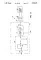
- FIG. 2is a functional block diagram of a drop detection apparatus embodying the invention
- FIG. 3is a circuit schematic diagram showing a drop detection circuit according to invention
- FIG. 4is a perspective view of a portion of the infusion device, showing a mounting receptacle for a drop detector assembly.
- FIG. 5is a perspective view of a drop chamber and drop detector assembly, showing the optical path coverage of the drop detector
- FIG. 6is a waveform diagram representing typical input and output of a portion of a circuit as in FIG. 3;
- FIG. 7illustrates typical output waveforms of a circuit as in FIG. 3.
- FIG. 8is a flowchart representing the drop discrimination process utilized in an apparatus embodying the invention.
- a medical infusion device worn by a patientis generally designated by the reference numeral 10.
- the infusion deviceincludes a pump for the enteral administration of fluids. It is to be understood that while the preferred embodiment is shown for a medical infusion device, the invention can be similarly used with any device making use of a drop chamber.
- the deviceis capable of being attached to the belt of a patient 11 in use, while the patient 11 is completely ambulatory.
- the deviceis thus subjected to significant tilting, jarring, and accelerations that must be accurately compensated for in the internal mechanisms and circuits of the device 10.
- FIG. 2The block diagram of FIG. 2 represents the electrical interaction of the major electronic and electromechanical components of the device 10 and shows signal connections.
- a keypad 12allows operator input of device parameters, such as fluid flow rate, which are sent to a microprocessor 14.
- the microprocessor 14provides information to the patient on a display 16 and controls a motor-driven pump 18.
- Drop detector 20, described in detail below,has a drop chamber which is interposed in the fluid flow path between a fluid supply (not shown) and the pump 18.
- a sensor monitoring the drop chamberdetects the flow of fluid through the drop chamber and sends corresponding signals to drop detection electronics 21.
- the electronics 21filter unwanted components in the signals from the detector 20 and pass the remainder to the microprocessor 14.
- the microprocessor 14also returns control signals to the electronics 21, as described below.
- the pump 18feeds fluid for the patient at a rate set into the device by means of the keypad 12 and maintained by the microprocessor 14. All of the fluid that the pump 18 feeds to the patient 11 must pass through a drop chamber and no dripping occurs if the pump stops feeding fluid. Since the fluid can pass through the drop chamber only in the form of drops of fixed volume, the drop count is therefore an extremely accurate measure of the quantity of fluid supplied to the patient. Accurate drop detection therefore permits accurate metering of fluid flow and accurate control of the pump by the microprocessor 14.
- Drop detector 20includes a yoke 36 (see FIG. 4), which is mounted on device 10 and a drop chamber 22 (see FIG. 5), which is removably received within yoke 36, thus supporting the drop chamber 22 in the infusion device 10.
- Yoke 36has a passageway 36a, which receives drop chamber 22 in an upright position.
- Two infrared light emitting diodes 38preferably Seimens SFH 485-2 IRLEDs 38 are mounted side-by-side, so as to face into passageway 36a and drop chamber 22.
- Diodes 38are preferably directed along lines intersecting the axis of the drop chamber 22 and form an angle of 20 degrees. They are also preferably offset from the top of the drop chamber 22 by one-third of its height.
- FIG. 5illustrates the removable drop chamber 22, connected in series with and interrupting a delivery tube 24 that runs from a fluid source (not shown) to a patient (11 in FIG. 1). Fluid enters the drop chamber 22 from the top portion 26 of the tube 24 as shown in FIG. 5 and exits the chamber 22 through the bottom portion 28.
- the drop chamber 22is a sealed unit, except for the entrance and exit portions 26,28 of the tube 24, which penetrate the top and bottom of the chamber 22, respectively.
- the chamber 22has a generally frusto-conical light-transmissive sidewall 30, with the smaller diameter at its bottom.
- the top portion 26 of the tubeextends partially into the chamber 22, creating a drop formation area 32. Fluid accumulates at this area 32, until it forms a complete drop, which then falls to the bottom of the chamber 22.
- the dropsWhen the chamber 22 is tilted, as often happens when the infusion device 10 is used in an ambulatory manner shown in FIG. 1, the drops will not fall to the bottom of the chamber 22, but will fall onto the side of the sloped sidewall 30 of the chamber 22.
- the tilt angledetermines where the drop will hit the sidewall 30.
- the dropsdo not even fall, but tend to form a puddle on the sidewall 30 at position 34.
- a rectangular photodiode 40Mounted within the yoke 36 on the opposite side of the drop chamber 22 from the IRLEDs 38 is a rectangular photodiode 40, preferably a Vactec VTS 3092 photodiode, measuring 0.6 by 0.1 inches. It is mounted with its length parallel to the horizontal plane.
- the result of having two IRLEDs 38 opposite a single photodiode 40is to create a triangular optical path 41 that can be broken by a drop passing through any portion of the horizontal cross section of the chamber 22 (as shown in FIG. 5). If a drop contacts the sidewall 30 of the chamber 22 and then slides down the wall 30, regardless of which side it travels on, the drop will pass through the optical path between the two IRLEDs 38 and the photodiode 40.
- the photodiode 40is preferably connected to a drop detection circuit 41, schematically illustrated in FIG. 3.
- the drop detection circuitfilters out any unwanted portions of the signal from the photodiode 40 and amplifies the remainder of the signal, which is presumably caused by drop flow.
- the microprocessor 14processes the output signal from the circuit 41 to determine if proper flow is occurring and control pump 18 and display 16 accordingly.
- the drop detection circuit 41 shown in FIG. 3includes a driver circuit 42 that powers the two IRLEDs 38 and preferably provides a constant current supply to the IRLEDs 38 to maintain constant optical output. Any variation in the optical output would add unwanted signals to the photodiode 40, so constant optical output is important.
- a detector circuit 44receives electrical signals from the photodiode 40 and converts them to a signal indicating whether or not a drop is flowing.
- the detector circuit 44includes an operational amplifier 46, which amplifies the signal from the photodiode 40, after which it is applied to a lowpass filter 47.
- Filter 47is a switched capacitor lowpass filter, preferably a National Semiconductor Corporation LMF60-100. It filters out any components of the signal above a nominal cut-off frequency that is determined by an input clock signal 48 from the microprocessor 14 of the infusion device 10.
- the drop rateis directly proportional to the speed of the pump motor, which is constant and controlled by the microprocessor.
- the flow ratei.e. number of drops per unit time
- the microprocessorthus produces a filter clock signal 48 to control the cut-off frequency of the filter 47, based on this known speed and drop rate.
- the filter clockis at 350 Hz
- filter 47is designed to divide the filter clock by 100 to derive a cutoff frequency of 3.5 hz.
- capacitor C1Connected in series between the photodiode 40 and lowpass filter 47 is a capacitor C1. This capacitor blocks the DC component of the voltage produced by the photodiode 40, which is typically developed in response to the ambient light level. Only variable signals, such as those caused by drops, are passed to the filter 47. Some changes in ambient light may also produce signals that will pass through the capacitor to the filter 47. However, the cutoff frequency determined by the microprocessor tends to limit the filter's passband narrowly to only signals produced by drops.
- Blocking the DC component of the signal from photodiode 40also allows the relatively weak signals from the photodiode to be amplified with a much higher gain than would normally be possible. If the gain of the operational amplifier 46 in filter 47 (approximately 70) were applied to the signals of conventional drop photodetectors, the amplifier 46 would saturate.
- the signalsare passed through a differentiator circuit 49.
- This circuit 49The effect of this circuit 49 on the signals is illustrated in FIG. 6, wherein the upper waveform 6a represents typical output of the lowpass filter 47, which is input to the circuit 49, and lower waveform 6b represents the output of the circuit 49.
- the circuitoutputs a positive pulse in response to a negative slope of waveform 6a, preferably a slope greater than 0.3 volts per second, which has been found to be a reliable indicator of drop flow.
- the duration of the positive pulseequals the duration of the negative slope of waveform 6a.
- the signalsare then passed through logic invertor 50 and on to the microprocessor 14.
- the microprocessor 14For the microprocessor 14 to consider signals from the drop detection circuit 44 as representing a valid drop, there must be a rising edge, a falling edge and a subsequent minimal hold time, preferably 50 milliseconds. As seen in FIG. 7, at least three different types of inputs from the drop detection circuit 44 to the microprocessor 14 will result in a valid drop being detected.
- waveform 7a of FIG. 7a long positive pulse is followed by the necessary hold time. This can occur when the drop chamber 22 is tilted at a high angle and a drop slides down the side of the drop chamber 22 past the photodiode more slowly than if it had fallen to the bottom of the chamber 22.
- waveform 7b of FIG. 7a narrow positive pulse is followed by the requisite hold time. This represents a drop passing quickly past the photodiode, such as when the chamber 22 is in its proper vertical position.
- waveform 7c of FIG. 7several narrow positive pulses are followed by the requisite hold time. This can represent any of various conditions, one of which is a drop bounding from excessive agitation of the infusion device 10.
- FIG. 8is a flowchart representing the process performed by microprocessor 14 to determine if a valid drop has occurred, based upon signals such as those illustrated in FIG. 7.
- Processor 14performs this routine every 1.36 msec. on an interrupt basis.
- the microprocessor 14makes use of three software flags to keep track of the transitions in the signal received from drop detection electronics 21.
- the flag DROP 13 ACKis raised upon the occurrence of a negative transition if not previously set.
- the second and third flagsreflect past states of DROP -- DETECT the bit in microprocessor 14 memory that shows the status of drop detection electronics 21.
- Flag LAST -- DROPshows the status of DROP -- DETECT at the end of the previous iteration; flag THIS -- DROP shows that status of DROP -- DETECT at the end of the current iteration.
- Timer T -- HOLDis tested at block 112 to determine if 50 msec has passed since the last transition of DROP -- DETECT. If 50 msec has passed, the software tests LAST -- DROP in block 114 to get the status of DROP -- DETECT in the previous iteration, otherwise execution passes to block 120. If LAST -- DROP is low at block 114, DROP -- ACK is tested in block 118, otherwise execution passes to block 120. If DROP -- ACK is high at block 118, execution passes to block 120. This signifies that the drop has already been acknowledged and counted by the microprocessor 14, as will be seen below.
- Flags THIS -- DROP and LAST -- DROPare compared at block 120. If they are not equal, a transition of DROP -- DETECT has occurred, and DROP -- ACK and T -- HOLD are reset at block 124, and execution passes to block 126; if they are equal, T -- HOLD is incremented, and execution continues at block 126.
- LAST -- DROPis set equal to THIS -- DROP and then THIS -- DROP is set equal to DROP -- DETECT. The routine then ends at block 128.
- DROP -- ACKwill be set to 1 at block 118 upon the occurrence of a negative-going transition followed by a 50 msec hold. Thereafter, blocks 112, 120, 122 and 126 are performed in repeated sequential passes until a positive transition is seen by block 120. In the next pass through the routine, blocks 112, 120, 122 or 124, and 126 are performed until T -- HOLD exceeds 50 msec. At this point, a valid drop is detected, and DROP -- ACK is set until the next transition of DROP -- DETECT.
- waveform 7b in FIG. 7When a waveform such as waveform 7b in FIG. 7 is encountered, it is handled in precisely the same manner as just described, except that the negative transition is detected much sooner than it was with respect to waveform 7a.
Landscapes
- Physics & Mathematics (AREA)
- Health & Medical Sciences (AREA)
- Life Sciences & Earth Sciences (AREA)
- General Physics & Mathematics (AREA)
- Biomedical Technology (AREA)
- Animal Behavior & Ethology (AREA)
- Geophysics (AREA)
- Vascular Medicine (AREA)
- Engineering & Computer Science (AREA)
- Anesthesiology (AREA)
- General Life Sciences & Earth Sciences (AREA)
- Heart & Thoracic Surgery (AREA)
- Hematology (AREA)
- Fluid Mechanics (AREA)
- General Health & Medical Sciences (AREA)
- Public Health (AREA)
- Veterinary Medicine (AREA)
- Optics & Photonics (AREA)
- Infusion, Injection, And Reservoir Apparatuses (AREA)
- Analysing Materials By The Use Of Radiation (AREA)
- Application Of Or Painting With Fluid Materials (AREA)
- Investigating Or Analysing Biological Materials (AREA)
Abstract
Description
Claims (13)
Priority Applications (18)
| Application Number | Priority Date | Filing Date | Title |
|---|---|---|---|
| US07/678,639US5256155A (en) | 1991-04-01 | 1991-04-01 | Drop detection method and apparatus |
| IL10141392AIL101413A (en) | 1991-04-01 | 1992-03-30 | Drop detection method and apparatus |
| DE69232670TDE69232670T2 (en) | 1991-04-01 | 1992-03-31 | Drop detector and method |
| EP92910567AEP0578764B1 (en) | 1991-04-01 | 1992-03-31 | Drop detection method and apparatus |
| CA002102424ACA2102424C (en) | 1991-04-01 | 1992-03-31 | Drop detection method and apparatus |
| EP96120460AEP0768092B1 (en) | 1991-04-01 | 1992-03-31 | Drop detection method and apparatus |
| DE69221135TDE69221135T2 (en) | 1991-04-01 | 1992-03-31 | DROP DETECTOR |
| AU17677/92AAU668089B2 (en) | 1991-04-01 | 1992-03-31 | Drop detection method and apparatus |
| DE69231867TDE69231867T2 (en) | 1991-04-01 | 1992-03-31 | drop detector |
| EP96120864AEP0770403B1 (en) | 1991-04-01 | 1992-03-31 | Drop detection method and apparatus |
| PCT/US1992/002435WO1992017227A2 (en) | 1991-04-01 | 1992-03-31 | Drop detection method and apparatus |
| IE921024AIE79030B1 (en) | 1991-04-01 | 1992-03-31 | Drop detection method and apparatus |
| US07/861,672US5346466A (en) | 1991-04-01 | 1992-04-01 | Drop detection method and apparatus |
| MX9201484AMX9201484A (en) | 1991-04-01 | 1992-04-01 | APPARATUS AND METHOD FOR DOSING AND VERIFYING THE PROPORTION OF A FLUID ADMINISTERED TO A PATIENT. |
| TW081102634ATW207955B (en) | 1991-04-01 | 1992-04-07 | |
| US07/970,323US5415641A (en) | 1991-04-01 | 1992-11-02 | Drop detection method and apparatus |
| AU56181/96AAU5618196A (en) | 1991-04-01 | 1996-06-25 | Drop detection method and apparatus |
| AU98192/98AAU9819298A (en) | 1991-04-01 | 1998-12-24 | Drop detection method and apparatus |
Applications Claiming Priority (1)
| Application Number | Priority Date | Filing Date | Title |
|---|---|---|---|
| US07/678,639US5256155A (en) | 1991-04-01 | 1991-04-01 | Drop detection method and apparatus |
Related Child Applications (1)
| Application Number | Title | Priority Date | Filing Date |
|---|---|---|---|
| US07/861,672Continuation-In-PartUS5346466A (en) | 1991-04-01 | 1992-04-01 | Drop detection method and apparatus |
Publications (1)
| Publication Number | Publication Date |
|---|---|
| US5256155Atrue US5256155A (en) | 1993-10-26 |
Family
ID=24723654
Family Applications (2)
| Application Number | Title | Priority Date | Filing Date |
|---|---|---|---|
| US07/678,639Expired - LifetimeUS5256155A (en) | 1991-04-01 | 1991-04-01 | Drop detection method and apparatus |
| US07/861,672Expired - LifetimeUS5346466A (en) | 1991-04-01 | 1992-04-01 | Drop detection method and apparatus |
Family Applications After (1)
| Application Number | Title | Priority Date | Filing Date |
|---|---|---|---|
| US07/861,672Expired - LifetimeUS5346466A (en) | 1991-04-01 | 1992-04-01 | Drop detection method and apparatus |
Country Status (10)
| Country | Link |
|---|---|
| US (2) | US5256155A (en) |
| EP (3) | EP0768092B1 (en) |
| AU (2) | AU668089B2 (en) |
| CA (1) | CA2102424C (en) |
| DE (3) | DE69231867T2 (en) |
| IE (1) | IE79030B1 (en) |
| IL (1) | IL101413A (en) |
| MX (1) | MX9201484A (en) |
| TW (1) | TW207955B (en) |
| WO (1) | WO1992017227A2 (en) |
Cited By (65)
| Publication number | Priority date | Publication date | Assignee | Title |
|---|---|---|---|---|
| US5621392A (en)* | 1991-11-05 | 1997-04-15 | Hospal Ltd. | Flow detector |
| US5690612A (en)* | 1993-07-23 | 1997-11-25 | Icu Medical, Inc. | Medical connection indicator |
| US5957898A (en) | 1997-05-20 | 1999-09-28 | Baxter International Inc. | Needleless connector |
| DE19859811A1 (en)* | 1998-12-23 | 2000-06-29 | Hilekes Guido | Contrast agent injection system |
| US6261282B1 (en) | 1997-05-20 | 2001-07-17 | Baxter International Inc. | Needleless connector |
| US20020195105A1 (en)* | 2000-01-13 | 2002-12-26 | Brent Blue | Method and apparatus for providing and controlling oxygen supply |
| US6572592B1 (en) | 1991-12-18 | 2003-06-03 | Icu Medical, Inc. | Medical valve and method of use |
| US6599273B1 (en) | 1991-12-18 | 2003-07-29 | Icu Medical, Inc. | Fluid transfer device and method of use |
| US6635044B2 (en) | 1995-12-15 | 2003-10-21 | Icu Medical, Inc. | Medical valve with fluid escape space |
| US6695817B1 (en) | 2000-07-11 | 2004-02-24 | Icu Medical, Inc. | Medical valve with positive flow characteristics |
| US20070208306A1 (en)* | 2006-03-02 | 2007-09-06 | Sherwood Services Ag | Pumping apparatus with secure loading features |
| US20070208305A1 (en)* | 2006-03-02 | 2007-09-06 | Sherwood Services Ag | Pump set with secure loading features |
| US20070253833A1 (en)* | 2006-03-02 | 2007-11-01 | Tyco Healthcare Group Lp | Pump Set with Safety Interlock |
| US20080135725A1 (en)* | 2006-12-11 | 2008-06-12 | Tyco Healthcare Group Lp | Pump set and pump with electromagnetic radiation operated interlock |
| US20080167617A1 (en)* | 2007-01-05 | 2008-07-10 | Tyco Heathcare Group Lp | Pump set for administering fluid with secure loading features and manufacture of component therefor |
| US20100082011A1 (en)* | 2008-09-29 | 2010-04-01 | Tyco Healthcare Group Lp | Fluid detection in an enteral feeding set |
| US7753338B2 (en) | 2006-10-23 | 2010-07-13 | Baxter International Inc. | Luer activated device with minimal fluid displacement |
| US7763005B2 (en) | 2006-03-02 | 2010-07-27 | Covidien Ag | Method for using a pump set having secure loading features |
| US7824393B2 (en) | 2004-11-05 | 2010-11-02 | Icu Medical, Inc. | Medical connector having high flow rate characteristics |
| US7846131B2 (en) | 2005-09-30 | 2010-12-07 | Covidien Ag | Administration feeding set and flow control apparatus with secure loading features |
| US20110021979A1 (en)* | 2006-03-02 | 2011-01-27 | Hudson Joseph A | Enteral Feeding Set and Interlock Device Therefor |
| US7981090B2 (en) | 2006-10-18 | 2011-07-19 | Baxter International Inc. | Luer activated device |
| USD644731S1 (en) | 2010-03-23 | 2011-09-06 | Icu Medical, Inc. | Medical connector |
| US8105314B2 (en) | 2006-10-25 | 2012-01-31 | Icu Medical, Inc. | Medical connector |
| US8154274B2 (en) | 2010-05-11 | 2012-04-10 | Tyco Healthcare Group Lp | Safety interlock |
| US8221363B2 (en) | 2006-10-18 | 2012-07-17 | Baxter Healthcare S.A. | Luer activated device with valve element under tension |
| WO2013049676A1 (en)* | 2011-09-30 | 2013-04-04 | Hospira, Inc. | Intravenous flow rate controller |
| US8454579B2 (en) | 2009-03-25 | 2013-06-04 | Icu Medical, Inc. | Medical connector with automatic valves and volume regulator |
| US8522832B2 (en) | 2009-07-29 | 2013-09-03 | Icu Medical, Inc. | Fluid transfer devices and methods of use |
| US8758306B2 (en) | 2010-05-17 | 2014-06-24 | Icu Medical, Inc. | Medical connectors and methods of use |
| WO2014130974A1 (en)* | 2013-02-25 | 2014-08-28 | Shift Labs, Inc. | Device, method, and system for monitoring the delivery of fluids through a drip chamber |
| US20160320228A1 (en)* | 2015-04-29 | 2016-11-03 | Covidien Lp | Detection of Malfunction of Flow Monitoring System of Flow Control Apparatus |
| USD786427S1 (en) | 2014-12-03 | 2017-05-09 | Icu Medical, Inc. | Fluid manifold |
| USD793551S1 (en) | 2014-12-03 | 2017-08-01 | Icu Medical, Inc. | Fluid manifold |
| US9849236B2 (en) | 2013-11-25 | 2017-12-26 | Icu Medical, Inc. | Methods and systems for filling IV bags with therapeutic fluid |
| US9883987B2 (en) | 2011-12-22 | 2018-02-06 | Icu Medical, Inc. | Fluid transfer devices and methods of use |
| US10022498B2 (en) | 2011-12-16 | 2018-07-17 | Icu Medical, Inc. | System for monitoring and delivering medication to a patient and method of using the same to minimize the risks associated with automated therapy |
| US10166328B2 (en) | 2013-05-29 | 2019-01-01 | Icu Medical, Inc. | Infusion system which utilizes one or more sensors and additional information to make an air determination regarding the infusion system |
| USD837983S1 (en) | 2015-12-04 | 2019-01-08 | Icu Medical, Inc. | Fluid transfer device |
| US10251805B2 (en) | 2012-03-29 | 2019-04-09 | GaitTronics inc. | Control system and device for patient assist |
| USD851745S1 (en) | 2016-07-19 | 2019-06-18 | Icu Medical, Inc. | Medical fluid transfer system |
| US10342917B2 (en) | 2014-02-28 | 2019-07-09 | Icu Medical, Inc. | Infusion system and method which utilizes dual wavelength optical air-in-line detection |
| US10369349B2 (en) | 2013-12-11 | 2019-08-06 | Icu Medical, Inc. | Medical fluid manifold |
| US10430761B2 (en) | 2011-08-19 | 2019-10-01 | Icu Medical, Inc. | Systems and methods for a graphical interface including a graphical representation of medical data |
| US10463788B2 (en) | 2012-07-31 | 2019-11-05 | Icu Medical, Inc. | Patient care system for critical medications |
| US10578474B2 (en) | 2012-03-30 | 2020-03-03 | Icu Medical, Inc. | Air detection system and method for detecting air in a pump of an infusion system |
| US10596316B2 (en) | 2013-05-29 | 2020-03-24 | Icu Medical, Inc. | Infusion system and method of use which prevents over-saturation of an analog-to-digital converter |
| US10635784B2 (en) | 2007-12-18 | 2020-04-28 | Icu Medical, Inc. | User interface improvements for medical devices |
| US10656894B2 (en) | 2017-12-27 | 2020-05-19 | Icu Medical, Inc. | Synchronized display of screen content on networked devices |
| CN111821541A (en)* | 2020-08-06 | 2020-10-27 | 东莞市人民医院 | Infusion speed detector |
| US10850024B2 (en) | 2015-03-02 | 2020-12-01 | Icu Medical, Inc. | Infusion system, device, and method having advanced infusion features |
| US10874793B2 (en) | 2013-05-24 | 2020-12-29 | Icu Medical, Inc. | Multi-sensor infusion system for detecting air or an occlusion in the infusion system |
| US11020541B2 (en) | 2016-07-25 | 2021-06-01 | Icu Medical, Inc. | Systems, methods, and components for trapping air bubbles in medical fluid transfer modules and systems |
| US11135360B1 (en) | 2020-12-07 | 2021-10-05 | Icu Medical, Inc. | Concurrent infusion with common line auto flush |
| US11246985B2 (en) | 2016-05-13 | 2022-02-15 | Icu Medical, Inc. | Infusion pump system and method with common line auto flush |
| US11278671B2 (en) | 2019-12-04 | 2022-03-22 | Icu Medical, Inc. | Infusion pump with safety sequence keypad |
| US11324888B2 (en) | 2016-06-10 | 2022-05-10 | Icu Medical, Inc. | Acoustic flow sensor for continuous medication flow measurements and feedback control of infusion |
| US11344673B2 (en) | 2014-05-29 | 2022-05-31 | Icu Medical, Inc. | Infusion system and pump with configurable closed loop delivery rate catch-up |
| US11344668B2 (en) | 2014-12-19 | 2022-05-31 | Icu Medical, Inc. | Infusion system with concurrent TPN/insulin infusion |
| US11464905B2 (en) | 2013-02-25 | 2022-10-11 | Shift Labs, Inc. | Monitoring device including an emitter emitting electromagnetic radiation and a detector positioned to receive the radiation to determine one or more rolling average flow rates |
| US11590057B2 (en) | 2020-04-03 | 2023-02-28 | Icu Medical, Inc. | Systems, methods, and components for transferring medical fluids |
| US11883361B2 (en) | 2020-07-21 | 2024-01-30 | Icu Medical, Inc. | Fluid transfer devices and methods of use |
| US12350233B2 (en) | 2021-12-10 | 2025-07-08 | Icu Medical, Inc. | Medical fluid compounding systems with coordinated flow control |
| USD1091564S1 (en) | 2021-10-13 | 2025-09-02 | Icu Medical, Inc. | Display screen or portion thereof with graphical user interface for a medical device |
| US12440661B2 (en) | 2022-05-18 | 2025-10-14 | Icu Medical, Inc. | Medical fluid transfer device |
Families Citing this family (34)
| Publication number | Priority date | Publication date | Assignee | Title |
|---|---|---|---|---|
| US5704923A (en)* | 1995-08-31 | 1998-01-06 | Chiu-Hsiung; Chiang | Liquid level detector and alarm device for drip infusion sets |
| US5843045A (en)* | 1997-01-17 | 1998-12-01 | Dupont; Frank Stuart | Infusion illuminator |
| US6261262B1 (en) | 1997-06-12 | 2001-07-17 | Abbott Laboratories | Pump with anti-free flow feature |
| GB2331742B (en)* | 1997-11-28 | 2002-07-17 | South Staffordshire Water Plc | Monitoring the addition of a liquid agent to another liquid |
| US6383210B1 (en) | 2000-06-02 | 2002-05-07 | Innercool Therapies, Inc. | Method for determining the effective thermal mass of a body or organ using cooling catheter |
| US6719779B2 (en) | 2000-11-07 | 2004-04-13 | Innercool Therapies, Inc. | Circulation set for temperature-controlled catheter and method of using the same |
| US6585752B2 (en) | 1998-06-23 | 2003-07-01 | Innercool Therapies, Inc. | Fever regulation method and apparatus |
| US6384402B1 (en) | 1998-04-29 | 2002-05-07 | Automated Merchandising Systems | Optical vend-sensing system for control of vending machine |
| US6299275B1 (en) | 1999-07-14 | 2001-10-09 | Hewlett-Packard Company | Thermal drop detector and method of thermal drop detection for use in inkjet printing devices |
| US6719723B2 (en) | 2000-12-06 | 2004-04-13 | Innercool Therapies, Inc. | Multipurpose catheter assembly |
| US6732014B2 (en) | 2001-02-27 | 2004-05-04 | Crane Co. | System for accomplishing product detection |
| US6708079B2 (en) | 2001-06-01 | 2004-03-16 | Automated Merchandising Systems | Optical vend-sensing system for control of vending machine |
| US8548625B2 (en)* | 2001-08-23 | 2013-10-01 | Crane Merchandising Systems, Inc. | Optical vend sensing system for product delivery detection |
| EP1440420A2 (en) | 2001-10-24 | 2004-07-28 | Crane Co. | Apparatus and methodology of detecting fulfillment of customer vend request |
| US20030181865A1 (en)* | 2002-03-21 | 2003-09-25 | Kent Abrahamson | Pump and tube set thereof |
| US6942473B2 (en)* | 2002-03-21 | 2005-09-13 | Hospira, Inc. | Pump and tube set thereof |
| US6877877B2 (en)* | 2003-02-13 | 2005-04-12 | Embo-Optics, Llc | Single intraveneous drip component illumination device |
| US7300453B2 (en) | 2003-02-24 | 2007-11-27 | Innercool Therapies, Inc. | System and method for inducing hypothermia with control and determination of catheter pressure |
| US7565222B2 (en)* | 2004-01-15 | 2009-07-21 | Fawn Engineering Corporation | Economical optical system to provide reasonable assurance of completed vend or vendible items from vending machines |
| US7446302B2 (en)* | 2004-07-09 | 2008-11-04 | Automated Merchandising Systems, Inc. | Optical vend-sensing system for control of vending machine |
| EP2582418B1 (en) | 2010-06-17 | 2019-05-15 | Koninklijke Philips N.V. | System for monitoring the position of a tube's distal end relative to a blood vessel |
| CN102218178B (en)* | 2011-06-14 | 2012-09-05 | 陈清美 | Observer convenient for observing infusion droplets |
| JP6089169B2 (en)* | 2013-04-15 | 2017-03-08 | 株式会社ジェイ・エム・エス | Infusion pump |
| CN104368062A (en)* | 2013-08-13 | 2015-02-25 | 孝感亚华电子科技有限公司 | Grooved optical level sensor for intravenous injection |
| US20150133861A1 (en) | 2013-11-11 | 2015-05-14 | Kevin P. McLennan | Thermal management system and method for medical devices |
| IN2014MU00233A (en) | 2014-01-22 | 2015-09-11 | Shivani Scient Ind Private Ltd | |
| US10143795B2 (en) | 2014-08-18 | 2018-12-04 | Icu Medical, Inc. | Intravenous pole integrated power, control, and communication system and method for an infusion pump |
| JPWO2016147519A1 (en)* | 2015-03-16 | 2017-12-28 | テルモ株式会社 | Infusion detection device and infusion pump using the same |
| NZ737340A (en) | 2015-05-26 | 2019-06-28 | Icu Medical Inc | Disposable infusion fluid delivery device for programmable large volume drug delivery |
| KR101973969B1 (en)* | 2016-08-03 | 2019-04-30 | 주식회사한빛엠디 | Flow Rate Monitering Device for Intravenous Fluid |
| JP6983709B2 (en)* | 2018-03-29 | 2021-12-17 | 株式会社日立製作所 | Analytical system and analytical method |
| USD939079S1 (en) | 2019-08-22 | 2021-12-21 | Icu Medical, Inc. | Infusion pump |
| USD1052728S1 (en) | 2021-11-12 | 2024-11-26 | Icu Medical, Inc. | Medical fluid infusion pump |
| WO2024200213A1 (en)* | 2023-03-24 | 2024-10-03 | droptical GmbH | Device for detecting at least one drop |
Citations (10)
| Publication number | Priority date | Publication date | Assignee | Title |
|---|---|---|---|---|
| US4058699A (en)* | 1975-08-01 | 1977-11-15 | Arthur D. Little, Inc. | Radiant zone heating apparatus and method |
| US4490140A (en)* | 1982-07-30 | 1984-12-25 | Abbott Laboratories | Intravenous monitoring system utilizing a dynamic reference threshold |
| US4498901A (en)* | 1982-07-30 | 1985-02-12 | Abbott Laboratories | Intravenous monitoring system utilizing a dynamic reference threshold |
| US4533350A (en)* | 1983-05-10 | 1985-08-06 | Anatros Corporation | Parenteral solution delivery control system |
| WO1986003002A1 (en)* | 1984-11-07 | 1986-05-22 | Baxter Travenol Laboratories, Inc. | Drop detection system with mirror element |
| EP0209659A2 (en)* | 1985-07-16 | 1987-01-28 | B. Braun-SSC AG | Drop detector |
| US4680462A (en)* | 1984-12-11 | 1987-07-14 | Baxter Travenol Laboratories, Inc. | Fluid drop detection system |
| US4718896A (en)* | 1986-01-10 | 1988-01-12 | Abbott Laboratories | Apparatus and method for controlling the flow of fluid through an administration set |
| US4720636A (en)* | 1984-08-06 | 1988-01-19 | Abbott Laboratories | Drop detecting system which operates under different ambient light conditions |
| US5012496A (en)* | 1989-11-07 | 1991-04-30 | Acumetric, Inc. | Drop counting system |
Family Cites Families (1)
| Publication number | Priority date | Publication date | Assignee | Title |
|---|---|---|---|---|
| US5533350A (en)* | 1994-12-16 | 1996-07-09 | Robertshaw Controls Company | Defrost control of a refrigeration system utilizing ambient air temperature determination |
- 1991
- 1991-04-01USUS07/678,639patent/US5256155A/ennot_activeExpired - Lifetime
- 1992
- 1992-03-30ILIL10141392Apatent/IL101413A/ennot_activeIP Right Cessation
- 1992-03-31WOPCT/US1992/002435patent/WO1992017227A2/enactiveIP Right Grant
- 1992-03-31DEDE69231867Tpatent/DE69231867T2/ennot_activeExpired - Lifetime
- 1992-03-31CACA002102424Apatent/CA2102424C/ennot_activeExpired - Lifetime
- 1992-03-31EPEP96120460Apatent/EP0768092B1/ennot_activeExpired - Lifetime
- 1992-03-31DEDE69232670Tpatent/DE69232670T2/ennot_activeExpired - Lifetime
- 1992-03-31EPEP92910567Apatent/EP0578764B1/ennot_activeExpired - Lifetime
- 1992-03-31DEDE69221135Tpatent/DE69221135T2/ennot_activeExpired - Lifetime
- 1992-03-31AUAU17677/92Apatent/AU668089B2/ennot_activeCeased
- 1992-03-31EPEP96120864Apatent/EP0770403B1/ennot_activeExpired - Lifetime
- 1992-03-31IEIE921024Apatent/IE79030B1/ennot_activeIP Right Cessation
- 1992-04-01USUS07/861,672patent/US5346466A/ennot_activeExpired - Lifetime
- 1992-04-01MXMX9201484Apatent/MX9201484A/enunknown
- 1992-04-07TWTW081102634Apatent/TW207955B/zhactive
- 1996
- 1996-06-25AUAU56181/96Apatent/AU5618196A/ennot_activeAbandoned
Patent Citations (11)
| Publication number | Priority date | Publication date | Assignee | Title |
|---|---|---|---|---|
| US4058699A (en)* | 1975-08-01 | 1977-11-15 | Arthur D. Little, Inc. | Radiant zone heating apparatus and method |
| US4490140A (en)* | 1982-07-30 | 1984-12-25 | Abbott Laboratories | Intravenous monitoring system utilizing a dynamic reference threshold |
| US4498901A (en)* | 1982-07-30 | 1985-02-12 | Abbott Laboratories | Intravenous monitoring system utilizing a dynamic reference threshold |
| US4533350A (en)* | 1983-05-10 | 1985-08-06 | Anatros Corporation | Parenteral solution delivery control system |
| US4720636A (en)* | 1984-08-06 | 1988-01-19 | Abbott Laboratories | Drop detecting system which operates under different ambient light conditions |
| WO1986003002A1 (en)* | 1984-11-07 | 1986-05-22 | Baxter Travenol Laboratories, Inc. | Drop detection system with mirror element |
| US4680462A (en)* | 1984-12-11 | 1987-07-14 | Baxter Travenol Laboratories, Inc. | Fluid drop detection system |
| US4786800A (en)* | 1984-12-11 | 1988-11-22 | Baxter International Inc. | Fluid drop detection and discrimination system |
| EP0209659A2 (en)* | 1985-07-16 | 1987-01-28 | B. Braun-SSC AG | Drop detector |
| US4718896A (en)* | 1986-01-10 | 1988-01-12 | Abbott Laboratories | Apparatus and method for controlling the flow of fluid through an administration set |
| US5012496A (en)* | 1989-11-07 | 1991-04-30 | Acumetric, Inc. | Drop counting system |
Cited By (197)
| Publication number | Priority date | Publication date | Assignee | Title |
|---|---|---|---|---|
| US5621392A (en)* | 1991-11-05 | 1997-04-15 | Hospal Ltd. | Flow detector |
| US7722576B2 (en) | 1991-12-18 | 2010-05-25 | Icu Medical, Inc. | Medical valve and method of use |
| US7722575B2 (en) | 1991-12-18 | 2010-05-25 | Icu Medical, Inc. | Medical valve and method of use |
| US7713249B2 (en) | 1991-12-18 | 2010-05-11 | Icu Medical, Inc. | Medical valve and method of use |
| US6599273B1 (en) | 1991-12-18 | 2003-07-29 | Icu Medical, Inc. | Fluid transfer device and method of use |
| US7717886B2 (en) | 1991-12-18 | 2010-05-18 | Icu Medical, Inc. | Medical valve and method of use |
| US6572592B1 (en) | 1991-12-18 | 2003-06-03 | Icu Medical, Inc. | Medical valve and method of use |
| US7713247B2 (en) | 1991-12-18 | 2010-05-11 | Icu Medical, Inc. | Medical valve and method of use |
| US6758833B2 (en) | 1991-12-18 | 2004-07-06 | Icu Medical, Inc. | Medical value |
| US7717885B2 (en) | 1991-12-18 | 2010-05-18 | Icu Medical, Inc. | Medical valve and method of use |
| US7717887B2 (en) | 1991-12-18 | 2010-05-18 | Icu Medical, Inc. | Medical valve and method of use |
| US7713248B2 (en) | 1991-12-18 | 2010-05-11 | Icu Medical, Inc. | Medical valve and method of use |
| US7717884B2 (en) | 1991-12-18 | 2010-05-18 | Icu Medical, Inc. | Medical valve and method of use |
| US6669673B2 (en) | 1991-12-18 | 2003-12-30 | Icu Medical, Inc. | Medical valve |
| US6682509B2 (en) | 1991-12-18 | 2004-01-27 | Icu Medical, Inc. | Medical valve and method of use |
| US7717883B2 (en) | 1991-12-18 | 2010-05-18 | Icu Medical, Inc. | Medical valve and method of use |
| US5690612A (en)* | 1993-07-23 | 1997-11-25 | Icu Medical, Inc. | Medical connection indicator |
| US5695466A (en)* | 1993-07-23 | 1997-12-09 | Icu Medical, Inc. | Medical connection indicator and method of use |
| US6635044B2 (en) | 1995-12-15 | 2003-10-21 | Icu Medical, Inc. | Medical valve with fluid escape space |
| US8002765B2 (en) | 1995-12-15 | 2011-08-23 | Icu Medical, Inc. | Medical valve with fluid escape space |
| US6261282B1 (en) | 1997-05-20 | 2001-07-17 | Baxter International Inc. | Needleless connector |
| US6669681B2 (en) | 1997-05-20 | 2003-12-30 | Baxter International Inc. | Needleless connector |
| US6344033B1 (en) | 1997-05-20 | 2002-02-05 | Baxter International, Inc. | Needleless connector |
| USRE43142E1 (en) | 1997-05-20 | 2012-01-24 | Baxter International, Inc. | Needleless connector |
| US5957898A (en) | 1997-05-20 | 1999-09-28 | Baxter International Inc. | Needleless connector |
| US20050107697A1 (en)* | 1998-12-23 | 2005-05-19 | Ralph Berke | Contrast agent injection system |
| DE19859811A1 (en)* | 1998-12-23 | 2000-06-29 | Hilekes Guido | Contrast agent injection system |
| DE19859811C2 (en)* | 1998-12-23 | 2001-05-10 | Hilekes Guido | Contrast agent injection system |
| US20020195105A1 (en)* | 2000-01-13 | 2002-12-26 | Brent Blue | Method and apparatus for providing and controlling oxygen supply |
| US8221391B2 (en) | 2000-07-11 | 2012-07-17 | Icu Medical, Inc. | Needleless medical connector |
| US7497849B2 (en) | 2000-07-11 | 2009-03-03 | Icu Medical, Inc. | High flow rate needleless medical connector |
| US7763199B2 (en) | 2000-07-11 | 2010-07-27 | Icu Medical, Inc. | Method of making a seal having slit formed therein |
| US8444628B2 (en) | 2000-07-11 | 2013-05-21 | Icu Medical, Inc. | Needleless medical connector |
| US8870850B2 (en) | 2000-07-11 | 2014-10-28 | Icu Medical, Inc. | Medical connector |
| US7628774B2 (en) | 2000-07-11 | 2009-12-08 | Icu Medical, Inc. | Needleless Medical Connector |
| US6916309B2 (en) | 2000-07-11 | 2005-07-12 | Icu Medical, Inc. | Medical valve with positive flow characteristics |
| US9238129B2 (en) | 2000-07-11 | 2016-01-19 | Icu Medical, Inc. | Medical connector |
| US6695817B1 (en) | 2000-07-11 | 2004-02-24 | Icu Medical, Inc. | Medical valve with positive flow characteristics |
| US9186494B2 (en) | 2004-11-05 | 2015-11-17 | Icu Medical, Inc. | Medical connector |
| US11883623B2 (en) | 2004-11-05 | 2024-01-30 | Icu Medical, Inc. | Medical connector |
| US9415200B2 (en) | 2004-11-05 | 2016-08-16 | Icu Medical, Inc. | Medical connector |
| US9884176B2 (en) | 2004-11-05 | 2018-02-06 | Icu Medical, Inc. | Medical connector |
| US7824393B2 (en) | 2004-11-05 | 2010-11-02 | Icu Medical, Inc. | Medical connector having high flow rate characteristics |
| US10722698B2 (en) | 2004-11-05 | 2020-07-28 | Icu Medical, Inc. | Medical connector |
| US7846131B2 (en) | 2005-09-30 | 2010-12-07 | Covidien Ag | Administration feeding set and flow control apparatus with secure loading features |
| US20100198144A1 (en)* | 2006-03-02 | 2010-08-05 | Covidien Ag | Method for using a pump set having secure loading features |
| US8142399B2 (en) | 2006-03-02 | 2012-03-27 | Tyco Healthcare Group Lp | Pump set with safety interlock |
| US20100198145A1 (en)* | 2006-03-02 | 2010-08-05 | Tyco Healthcare Group Lp | Pump set with safety interlock |
| US7763005B2 (en) | 2006-03-02 | 2010-07-27 | Covidien Ag | Method for using a pump set having secure loading features |
| US20110021979A1 (en)* | 2006-03-02 | 2011-01-27 | Hudson Joseph A | Enteral Feeding Set and Interlock Device Therefor |
| US7927304B2 (en) | 2006-03-02 | 2011-04-19 | Tyco Healthcare Group Lp | Enteral feeding pump and feeding set therefor |
| US20070253833A1 (en)* | 2006-03-02 | 2007-11-01 | Tyco Healthcare Group Lp | Pump Set with Safety Interlock |
| US7758551B2 (en) | 2006-03-02 | 2010-07-20 | Covidien Ag | Pump set with secure loading features |
| US9402789B2 (en) | 2006-03-02 | 2016-08-02 | Covidien Ag | Pump set having secure loading features |
| US20070208305A1 (en)* | 2006-03-02 | 2007-09-06 | Sherwood Services Ag | Pump set with secure loading features |
| US8052643B2 (en) | 2006-03-02 | 2011-11-08 | Tyco Healthcare Group Lp | Enteral feeding set and interlock device therefor |
| US7722573B2 (en) | 2006-03-02 | 2010-05-25 | Covidien Ag | Pumping apparatus with secure loading features |
| US8052642B2 (en) | 2006-03-02 | 2011-11-08 | Covidien Ag | Pumping apparatus with secure loading features |
| US7722562B2 (en) | 2006-03-02 | 2010-05-25 | Tyco Healthcare Group Lp | Pump set with safety interlock |
| US20070208306A1 (en)* | 2006-03-02 | 2007-09-06 | Sherwood Services Ag | Pumping apparatus with secure loading features |
| US8142404B2 (en) | 2006-03-02 | 2012-03-27 | Covidien Ag | Controller for pumping apparatus |
| US8221363B2 (en) | 2006-10-18 | 2012-07-17 | Baxter Healthcare S.A. | Luer activated device with valve element under tension |
| US7981090B2 (en) | 2006-10-18 | 2011-07-19 | Baxter International Inc. | Luer activated device |
| US7753338B2 (en) | 2006-10-23 | 2010-07-13 | Baxter International Inc. | Luer activated device with minimal fluid displacement |
| US9533137B2 (en) | 2006-10-25 | 2017-01-03 | Icu Medical, Inc. | Medical connector |
| US8628515B2 (en) | 2006-10-25 | 2014-01-14 | Icu Medical, Inc. | Medical connector |
| US8105314B2 (en) | 2006-10-25 | 2012-01-31 | Icu Medical, Inc. | Medical connector |
| US8398607B2 (en) | 2006-10-25 | 2013-03-19 | Icu Medical, Inc. | Medical connector |
| US7560686B2 (en) | 2006-12-11 | 2009-07-14 | Tyco Healthcare Group Lp | Pump set and pump with electromagnetic radiation operated interlock |
| US20080135725A1 (en)* | 2006-12-11 | 2008-06-12 | Tyco Healthcare Group Lp | Pump set and pump with electromagnetic radiation operated interlock |
| US8053721B2 (en) | 2006-12-11 | 2011-11-08 | Tyco Healthcare Group Lp | Pump set and pump with electromagnetic radiation operated interlock |
| US20090264824A1 (en)* | 2006-12-11 | 2009-10-22 | Tyco Healthcare Group Lp | Pump set and pump with electromagnetic radiation operated interlock |
| US20080167617A1 (en)* | 2007-01-05 | 2008-07-10 | Tyco Heathcare Group Lp | Pump set for administering fluid with secure loading features and manufacture of component therefor |
| US8529511B2 (en) | 2007-01-05 | 2013-09-10 | Covidien Lp | Pump set with secure loading features and related methods therefor |
| US8021336B2 (en) | 2007-01-05 | 2011-09-20 | Tyco Healthcare Group Lp | Pump set for administering fluid with secure loading features and manufacture of component therefor |
| US10635784B2 (en) | 2007-12-18 | 2020-04-28 | Icu Medical, Inc. | User interface improvements for medical devices |
| US20100082011A1 (en)* | 2008-09-29 | 2010-04-01 | Tyco Healthcare Group Lp | Fluid detection in an enteral feeding set |
| US8795225B2 (en) | 2008-09-29 | 2014-08-05 | Covidien Lp | Fluid detection in an enteral feeding set |
| US9642777B2 (en) | 2008-09-29 | 2017-05-09 | Covidien Lp | Fluid detection in an enteral feeding set |
| US12285584B2 (en) | 2009-03-25 | 2025-04-29 | Icu Medical, Inc. | Medical connector with elongated portion within seal collar |
| US11986618B1 (en) | 2009-03-25 | 2024-05-21 | Icu Medical, Inc. | Medical connector having elongated portion within seal collar |
| US10799692B2 (en) | 2009-03-25 | 2020-10-13 | Icu Medical, Inc. | Medical connectors and methods of use |
| US11931539B2 (en) | 2009-03-25 | 2024-03-19 | Icu Medical, Inc. | Medical connectors and methods of use |
| US11896795B2 (en) | 2009-03-25 | 2024-02-13 | Icu Medical, Inc | Medical connector having elongated portion within closely conforming seal collar |
| US8454579B2 (en) | 2009-03-25 | 2013-06-04 | Icu Medical, Inc. | Medical connector with automatic valves and volume regulator |
| US10391293B2 (en) | 2009-03-25 | 2019-08-27 | Icu Medical, Inc. | Medical connectors and methods of use |
| US9278206B2 (en) | 2009-03-25 | 2016-03-08 | Icu Medical, Inc. | Medical connectors and methods of use |
| US10086188B2 (en) | 2009-03-25 | 2018-10-02 | Icu Medical, Inc. | Medical connectors and methods of use |
| US12059545B2 (en) | 2009-03-25 | 2024-08-13 | Icu Medical, Inc. | Medical connector with elongated portion within seal collar |
| US12102786B2 (en) | 2009-03-25 | 2024-10-01 | Icu Medical, Inc. | Medical connector with elongated portion within seal collar |
| US9440060B2 (en) | 2009-03-25 | 2016-09-13 | Icu Medical, Inc. | Medical connectors and methods of use |
| US11376411B2 (en) | 2009-03-25 | 2022-07-05 | Icu Medical, Inc. | Medical connectors and methods of use |
| US11806308B2 (en) | 2009-07-29 | 2023-11-07 | Icu Medical, Inc. | Fluid transfer devices and methods of use |
| US9931276B2 (en) | 2009-07-29 | 2018-04-03 | Icu Medical, Inc. | Fluid transfer devices and methods of use |
| US10314765B2 (en) | 2009-07-29 | 2019-06-11 | Icu Medical, Inc. | Fluid transfer devices and methods of use |
| US12186270B2 (en) | 2009-07-29 | 2025-01-07 | Icu Medical, Inc. | Fluid transfer devices and methods of use |
| US11007119B2 (en) | 2009-07-29 | 2021-05-18 | Icu Medical, Inc. | Fluid transfer devices and methods of use |
| US8522832B2 (en) | 2009-07-29 | 2013-09-03 | Icu Medical, Inc. | Fluid transfer devices and methods of use |
| US9827163B2 (en) | 2009-07-29 | 2017-11-28 | Icu Medical, Inc. | Fluid transfer devices and methods of use |
| US9511989B2 (en) | 2009-07-29 | 2016-12-06 | Icu Medical, Inc. | Fluid transfer devices and methods of use |
| US8973622B2 (en) | 2009-07-29 | 2015-03-10 | Icu Medical, Inc. | Fluid transfer devices and methods of use |
| USD1029246S1 (en) | 2010-03-23 | 2024-05-28 | Icu Medical, Inc. | Medical connector seal |
| USD644731S1 (en) | 2010-03-23 | 2011-09-06 | Icu Medical, Inc. | Medical connector |
| USD1003434S1 (en) | 2010-03-23 | 2023-10-31 | Icu Medical, Inc. | Medical connector seal |
| US8154274B2 (en) | 2010-05-11 | 2012-04-10 | Tyco Healthcare Group Lp | Safety interlock |
| US8760146B2 (en) | 2010-05-11 | 2014-06-24 | Covidien Lp | Safety interlock |
| US9750926B2 (en) | 2010-05-17 | 2017-09-05 | Icu Medical, Inc. | Medical connectors and methods of use |
| US11071852B2 (en) | 2010-05-17 | 2021-07-27 | Icu Medical, Inc. | Medical connectors and methods of use |
| US10195413B2 (en) | 2010-05-17 | 2019-02-05 | Icu Medical, Inc. | Medical connectors and methods of use |
| US9205243B2 (en) | 2010-05-17 | 2015-12-08 | Icu Medical, Inc. | Medical connectors and methods of use |
| US9192753B2 (en) | 2010-05-17 | 2015-11-24 | Icu Medical, Inc. | Medical connectors and methods of use |
| US8758306B2 (en) | 2010-05-17 | 2014-06-24 | Icu Medical, Inc. | Medical connectors and methods of use |
| US10430761B2 (en) | 2011-08-19 | 2019-10-01 | Icu Medical, Inc. | Systems and methods for a graphical interface including a graphical representation of medical data |
| US12346879B2 (en) | 2011-08-19 | 2025-07-01 | Icu Medical, Inc. | Systems and methods for a graphical interface including a graphical representation of medical data |
| US11599854B2 (en) | 2011-08-19 | 2023-03-07 | Icu Medical, Inc. | Systems and methods for a graphical interface including a graphical representation of medical data |
| US11004035B2 (en) | 2011-08-19 | 2021-05-11 | Icu Medical, Inc. | Systems and methods for a graphical interface including a graphical representation of medical data |
| US11972395B2 (en) | 2011-08-19 | 2024-04-30 | Icu Medical, Inc. | Systems and methods for a graphical interface including a graphical representation of medical data |
| CN103842007B (en)* | 2011-09-30 | 2016-05-25 | 赫士睿股份有限公司 | Venous Flow Controller |
| CN103842007A (en)* | 2011-09-30 | 2014-06-04 | 赫士睿股份有限公司 | Intravenous flow rate controller |
| US9134736B2 (en) | 2011-09-30 | 2015-09-15 | Hospira, Inc. | Intravenous flow rate controller |
| WO2013049676A1 (en)* | 2011-09-30 | 2013-04-04 | Hospira, Inc. | Intravenous flow rate controller |
| US9134735B2 (en) | 2011-09-30 | 2015-09-15 | Hospira, Inc. | Intravenous flow rate controller |
| US10022498B2 (en) | 2011-12-16 | 2018-07-17 | Icu Medical, Inc. | System for monitoring and delivering medication to a patient and method of using the same to minimize the risks associated with automated therapy |
| US11376361B2 (en) | 2011-12-16 | 2022-07-05 | Icu Medical, Inc. | System for monitoring and delivering medication to a patient and method of using the same to minimize the risks associated with automated therapy |
| US11439570B2 (en) | 2011-12-22 | 2022-09-13 | Icu Medical, Inc. | Fluid transfer devices and methods of use |
| US12023304B2 (en) | 2011-12-22 | 2024-07-02 | Icu Medical, Inc. | Fluid transfer devices and methods of use |
| US11439571B2 (en) | 2011-12-22 | 2022-09-13 | Icu Medical, Inc. | Fluid transfer devices and methods of use |
| US10314764B2 (en) | 2011-12-22 | 2019-06-11 | Icu Medical, Inc. | Fluid transfer devices and methods of use |
| US9883987B2 (en) | 2011-12-22 | 2018-02-06 | Icu Medical, Inc. | Fluid transfer devices and methods of use |
| US10251805B2 (en) | 2012-03-29 | 2019-04-09 | GaitTronics inc. | Control system and device for patient assist |
| US10578474B2 (en) | 2012-03-30 | 2020-03-03 | Icu Medical, Inc. | Air detection system and method for detecting air in a pump of an infusion system |
| US11933650B2 (en) | 2012-03-30 | 2024-03-19 | Icu Medical, Inc. | Air detection system and method for detecting air in a pump of an infusion system |
| US11623042B2 (en) | 2012-07-31 | 2023-04-11 | Icu Medical, Inc. | Patient care system for critical medications |
| US12280239B2 (en) | 2012-07-31 | 2025-04-22 | Icu Medical, Inc. | Patient care system for critical medications |
| US10463788B2 (en) | 2012-07-31 | 2019-11-05 | Icu Medical, Inc. | Patient care system for critical medications |
| US9199036B2 (en) | 2013-02-25 | 2015-12-01 | Shift Labs, Inc. | Device, method, and system for monitoring the delivery of fluids through a drip chamber |
| US11464905B2 (en) | 2013-02-25 | 2022-10-11 | Shift Labs, Inc. | Monitoring device including an emitter emitting electromagnetic radiation and a detector positioned to receive the radiation to determine one or more rolling average flow rates |
| WO2014130974A1 (en)* | 2013-02-25 | 2014-08-28 | Shift Labs, Inc. | Device, method, and system for monitoring the delivery of fluids through a drip chamber |
| US10874793B2 (en) | 2013-05-24 | 2020-12-29 | Icu Medical, Inc. | Multi-sensor infusion system for detecting air or an occlusion in the infusion system |
| US12048831B2 (en) | 2013-05-24 | 2024-07-30 | Icu Medical, Inc. | Multi-sensor infusion system for detecting air or an occlusion in the infusion system |
| US11433177B2 (en) | 2013-05-29 | 2022-09-06 | Icu Medical, Inc. | Infusion system which utilizes one or more sensors and additional information to make an air determination regarding the infusion system |
| US10596316B2 (en) | 2013-05-29 | 2020-03-24 | Icu Medical, Inc. | Infusion system and method of use which prevents over-saturation of an analog-to-digital converter |
| US11596737B2 (en) | 2013-05-29 | 2023-03-07 | Icu Medical, Inc. | Infusion system and method of use which prevents over-saturation of an analog-to-digital converter |
| US10166328B2 (en) | 2013-05-29 | 2019-01-01 | Icu Medical, Inc. | Infusion system which utilizes one or more sensors and additional information to make an air determination regarding the infusion system |
| US12059551B2 (en) | 2013-05-29 | 2024-08-13 | Icu Medical, Inc. | Infusion system and method of use which prevents over-saturation of an analog-to-digital converter |
| US9849236B2 (en) | 2013-11-25 | 2017-12-26 | Icu Medical, Inc. | Methods and systems for filling IV bags with therapeutic fluid |
| US11541171B2 (en) | 2013-11-25 | 2023-01-03 | Icu Medical, Inc. | Methods and systems for filling IV bags with therapeutic fluid |
| US11364372B2 (en) | 2013-12-11 | 2022-06-21 | Icu Medical, Inc. | Check valve |
| US10369349B2 (en) | 2013-12-11 | 2019-08-06 | Icu Medical, Inc. | Medical fluid manifold |
| US10342917B2 (en) | 2014-02-28 | 2019-07-09 | Icu Medical, Inc. | Infusion system and method which utilizes dual wavelength optical air-in-line detection |
| US12083310B2 (en) | 2014-02-28 | 2024-09-10 | Icu Medical, Inc. | Infusion system and method which utilizes dual wavelength optical air-in-line detection |
| US11344673B2 (en) | 2014-05-29 | 2022-05-31 | Icu Medical, Inc. | Infusion system and pump with configurable closed loop delivery rate catch-up |
| USD890335S1 (en) | 2014-12-03 | 2020-07-14 | Icu Medical, Inc. | Fluid manifold |
| USD826400S1 (en) | 2014-12-03 | 2018-08-21 | Icu Medical, Inc. | Fluid manifold |
| USD786427S1 (en) | 2014-12-03 | 2017-05-09 | Icu Medical, Inc. | Fluid manifold |
| USD849939S1 (en) | 2014-12-03 | 2019-05-28 | Icu Medical, Inc. | Fluid manifold |
| USD793551S1 (en) | 2014-12-03 | 2017-08-01 | Icu Medical, Inc. | Fluid manifold |
| US11344668B2 (en) | 2014-12-19 | 2022-05-31 | Icu Medical, Inc. | Infusion system with concurrent TPN/insulin infusion |
| US10850024B2 (en) | 2015-03-02 | 2020-12-01 | Icu Medical, Inc. | Infusion system, device, and method having advanced infusion features |
| US12115337B2 (en) | 2015-03-02 | 2024-10-15 | Icu Medical, Inc. | Infusion system, device, and method having advanced infusion features |
| US10066981B2 (en)* | 2015-04-29 | 2018-09-04 | Kpr U.S., Llc | Detection of malfunction of flow monitoring system of flow control apparatus |
| US20160320228A1 (en)* | 2015-04-29 | 2016-11-03 | Covidien Lp | Detection of Malfunction of Flow Monitoring System of Flow Control Apparatus |
| USD1018849S1 (en) | 2015-12-04 | 2024-03-19 | Icu Medical, Inc. | Fluid transfer device |
| US10420927B2 (en) | 2015-12-04 | 2019-09-24 | Icu Medical, Inc. | Systems, methods, and components for transferring medical fluids |
| USD837983S1 (en) | 2015-12-04 | 2019-01-08 | Icu Medical, Inc. | Fluid transfer device |
| US10188849B2 (en) | 2015-12-04 | 2019-01-29 | Icu Medical, Inc. | Systems, methods, and components for transferring medical fluids |
| USD948044S1 (en) | 2015-12-04 | 2022-04-05 | Icu Medical, Inc. | Fluid transfer device |
| US11865295B2 (en) | 2015-12-04 | 2024-01-09 | Icu Medical, Inc. | Systems, methods, and components for transferring medical fluids |
| US11135416B2 (en) | 2015-12-04 | 2021-10-05 | Icu Medical, Inc. | Systems, methods, and components for transferring medical fluids |
| US11246985B2 (en) | 2016-05-13 | 2022-02-15 | Icu Medical, Inc. | Infusion pump system and method with common line auto flush |
| US12201811B2 (en) | 2016-05-13 | 2025-01-21 | Icu Medical, Inc. | Infusion pump system and method with common line auto flush |
| US12076531B2 (en) | 2016-06-10 | 2024-09-03 | Icu Medical, Inc. | Acoustic flow sensor for continuous medication flow measurements and feedback control of infusion |
| US11324888B2 (en) | 2016-06-10 | 2022-05-10 | Icu Medical, Inc. | Acoustic flow sensor for continuous medication flow measurements and feedback control of infusion |
| USD905228S1 (en) | 2016-07-19 | 2020-12-15 | Icu Medical, Inc. | Medical fluid transfer system |
| USD851745S1 (en) | 2016-07-19 | 2019-06-18 | Icu Medical, Inc. | Medical fluid transfer system |
| USD874644S1 (en) | 2016-07-19 | 2020-02-04 | Icu Medical, Inc. | Medical fluid transfer system |
| USD943732S1 (en) | 2016-07-19 | 2022-02-15 | Icu Medical, Inc. | Medical fluid transfer system |
| US12280249B2 (en) | 2016-07-25 | 2025-04-22 | Icu Medical, Inc. | Systems, methods, and components for trapping air bubbles in medical fluid transfer modules and systems |
| US11020541B2 (en) | 2016-07-25 | 2021-06-01 | Icu Medical, Inc. | Systems, methods, and components for trapping air bubbles in medical fluid transfer modules and systems |
| US11951293B2 (en) | 2016-07-25 | 2024-04-09 | Icu Medical, Inc. | Systems, methods, and components for trapping air bubbles in medical fluid transfer modules and systems |
| US11583637B2 (en) | 2016-07-25 | 2023-02-21 | Icu Medical, Inc. | Systems, methods, and components for trapping air bubbles in medical fluid transfer modules and systems |
| US11029911B2 (en) | 2017-12-27 | 2021-06-08 | Icu Medical, Inc. | Synchronized display of screen content on networked devices |
| US10656894B2 (en) | 2017-12-27 | 2020-05-19 | Icu Medical, Inc. | Synchronized display of screen content on networked devices |
| US11868161B2 (en) | 2017-12-27 | 2024-01-09 | Icu Medical, Inc. | Synchronized display of screen content on networked devices |
| US12333201B2 (en) | 2017-12-27 | 2025-06-17 | Icu Medical, Inc. | Synchronized display of screen content on networked devices |
| US11278671B2 (en) | 2019-12-04 | 2022-03-22 | Icu Medical, Inc. | Infusion pump with safety sequence keypad |
| US12268843B2 (en) | 2019-12-04 | 2025-04-08 | Icu Medical, Inc. | Infusion pump with safety sequence keypad |
| US12303464B2 (en) | 2020-04-03 | 2025-05-20 | Icu Medical, Inc. | Systems, methods, and components for transferring medical fluids |
| US11590057B2 (en) | 2020-04-03 | 2023-02-28 | Icu Medical, Inc. | Systems, methods, and components for transferring medical fluids |
| US12310921B2 (en) | 2020-07-21 | 2025-05-27 | Icu Medical, Inc. | Fluid transfer devices and methods of use |
| US11883361B2 (en) | 2020-07-21 | 2024-01-30 | Icu Medical, Inc. | Fluid transfer devices and methods of use |
| CN111821541A (en)* | 2020-08-06 | 2020-10-27 | 东莞市人民医院 | Infusion speed detector |
| US11135360B1 (en) | 2020-12-07 | 2021-10-05 | Icu Medical, Inc. | Concurrent infusion with common line auto flush |
| US12390586B2 (en) | 2020-12-07 | 2025-08-19 | Icu Medical, Inc. | Concurrent infusion with common line auto flush |
| USD1091564S1 (en) | 2021-10-13 | 2025-09-02 | Icu Medical, Inc. | Display screen or portion thereof with graphical user interface for a medical device |
| US12350233B2 (en) | 2021-12-10 | 2025-07-08 | Icu Medical, Inc. | Medical fluid compounding systems with coordinated flow control |
| US12440661B2 (en) | 2022-05-18 | 2025-10-14 | Icu Medical, Inc. | Medical fluid transfer device |
Also Published As
| Publication number | Publication date |
|---|---|
| DE69231867T2 (en) | 2002-04-18 |
| EP0768092A3 (en) | 1997-12-03 |
| DE69221135D1 (en) | 1997-09-04 |
| DE69232670D1 (en) | 2002-08-08 |
| WO1992017227A3 (en) | 1992-11-12 |
| DE69231867D1 (en) | 2001-07-12 |
| IL101413A0 (en) | 1992-11-15 |
| EP0578764B1 (en) | 1997-07-23 |
| MX9201484A (en) | 1993-02-01 |
| CA2102424C (en) | 2003-05-20 |
| IE921024A1 (en) | 1992-10-07 |
| DE69221135T2 (en) | 1997-11-27 |
| EP0770403A3 (en) | 1997-12-03 |
| AU1767792A (en) | 1992-11-02 |
| IE79030B1 (en) | 1998-04-08 |
| WO1992017227A2 (en) | 1992-10-15 |
| AU668089B2 (en) | 1996-04-26 |
| US5346466A (en) | 1994-09-13 |
| EP0770403A2 (en) | 1997-05-02 |
| TW207955B (en) | 1993-06-21 |
| IL101413A (en) | 1995-05-26 |
| EP0770403B1 (en) | 2001-06-06 |
| DE69232670T2 (en) | 2003-02-27 |
| EP0768092A2 (en) | 1997-04-16 |
| EP0578764A1 (en) | 1994-01-19 |
| CA2102424A1 (en) | 1992-10-02 |
| AU5618196A (en) | 1996-08-29 |
| EP0768092B1 (en) | 2002-07-03 |
Similar Documents
| Publication | Publication Date | Title |
|---|---|---|
| US5256155A (en) | Drop detection method and apparatus | |
| US5415641A (en) | Drop detection method and apparatus | |
| CA1240755A (en) | Empty container detector with drop sensor | |
| US4786800A (en) | Fluid drop detection and discrimination system | |
| EP0529569B1 (en) | Apparatus for controlling the rate of dripping of intravenous fluid | |
| US4665391A (en) | Empty container detector | |
| US4509943A (en) | Infusion control apparatus | |
| US8471231B2 (en) | Optical drop detector system featuring a plurality of light pulses for detecting a plurality of flows | |
| EP0441323B1 (en) | Drip detecting device | |
| US4181130A (en) | Drop discriminator system | |
| US4623331A (en) | Apparatus for the registration of drops in an infusion device | |
| US4680977A (en) | Optical flow sensor | |
| US4884065A (en) | Monitor for detecting tube position and air bubbles in tube | |
| US4449122A (en) | Proximity detector employing a crystal oscillator | |
| US4225791A (en) | Optical smoke detector circuit | |
| US5166667A (en) | Intravenous infusion counter and alarm apparatus | |
| JPH0438302B2 (en) | ||
| AU766731B2 (en) | Drop detection method and apparatus | |
| JPS6241028B2 (en) | ||
| JPH0698934A (en) | Instillation monitor device | |
| JPH0663135A (en) | Liquid infusion pump | |
| WO1993009406A1 (en) | Optical flow detector | |
| KR860001318B1 (en) | The detector for voltage inductive type | |
| AU9819298A (en) | Drop detection method and apparatus | |
| JPH0389192A (en) | Control apparatus of optical sensor |
Legal Events
| Date | Code | Title | Description |
|---|---|---|---|
| AS | Assignment | Owner name:SHERWOOD MEDICAL COMPANY Free format text:ASSIGNMENT OF ASSIGNORS INTEREST.;ASSIGNORS:YERLIKAYA, DENIS Y.;KROHN, RANDALL J.;REEL/FRAME:005737/0649 Effective date:19910513 | |
| STCF | Information on status: patent grant | Free format text:PATENTED CASE | |
| FEPP | Fee payment procedure | Free format text:PAYOR NUMBER ASSIGNED (ORIGINAL EVENT CODE: ASPN); ENTITY STATUS OF PATENT OWNER: LARGE ENTITY | |
| FPAY | Fee payment | Year of fee payment:4 | |
| AS | Assignment | Owner name:SHERWOOD SERVICES AG, SWITZERLAND Free format text:ASSIGNMENT OF ASSIGNORS INTEREST;ASSIGNOR:TYCO GROUP S.A.R.L.;REEL/FRAME:010180/0294 Effective date:19990406 Owner name:TYCO GROUP S.A.R.L., LUXEMBOURG Free format text:ASSIGNMENT OF ASSIGNORS INTEREST;ASSIGNOR:SHERWOOD MEDICAL COMPANY;REEL/FRAME:010255/0446 Effective date:19990406 | |
| FEPP | Fee payment procedure | Free format text:PAYER NUMBER DE-ASSIGNED (ORIGINAL EVENT CODE: RMPN); ENTITY STATUS OF PATENT OWNER: LARGE ENTITY Free format text:PAYOR NUMBER ASSIGNED (ORIGINAL EVENT CODE: ASPN); ENTITY STATUS OF PATENT OWNER: LARGE ENTITY | |
| FPAY | Fee payment | Year of fee payment:8 | |
| FPAY | Fee payment | Year of fee payment:12 | |
| AS | Assignment | Owner name:COVIDIEN AG, SWITZERLAND Free format text:CHANGE OF NAME;ASSIGNOR:SHERWOOD SERVICES AG;REEL/FRAME:021371/0142 Effective date:20070309 |