US5256151A - Safety syringe with retractible needle holder - Google Patents
Safety syringe with retractible needle holderDownload PDFInfo
- Publication number
- US5256151A US5256151AUS07/973,556US97355692AUS5256151AUS 5256151 AUS5256151 AUS 5256151AUS 97355692 AUS97355692 AUS 97355692AUS 5256151 AUS5256151 AUS 5256151A
- Authority
- US
- United States
- Prior art keywords
- needle
- protrusion
- piston
- recess
- holder body
- Prior art date
- Legal status (The legal status is an assumption and is not a legal conclusion. Google has not performed a legal analysis and makes no representation as to the accuracy of the status listed.)
- Expired - Fee Related
Links
- 239000012530fluidSubstances0.000claimsdescription6
- 238000006073displacement reactionMethods0.000claims1
- 208000012266Needlestick injuryDiseases0.000description2
- 230000000149penetrating effectEffects0.000description2
- 208000030507AIDSDiseases0.000description1
- 208000035473Communicable diseaseDiseases0.000description1
- 239000008280bloodSubstances0.000description1
- 210000004369bloodAnatomy0.000description1
- 230000000295complement effectEffects0.000description1
- 231100000206health hazardToxicity0.000description1
- 208000006454hepatitisDiseases0.000description1
- 231100000283hepatitisToxicity0.000description1
- 230000037431insertionEffects0.000description1
- 238000003780insertionMethods0.000description1
- 239000007788liquidSubstances0.000description1
- 230000001681protective effectEffects0.000description1
- 238000005086pumpingMethods0.000description1
Images


Classifications
- A—HUMAN NECESSITIES
- A61—MEDICAL OR VETERINARY SCIENCE; HYGIENE
- A61M—DEVICES FOR INTRODUCING MEDIA INTO, OR ONTO, THE BODY; DEVICES FOR TRANSDUCING BODY MEDIA OR FOR TAKING MEDIA FROM THE BODY; DEVICES FOR PRODUCING OR ENDING SLEEP OR STUPOR
- A61M5/00—Devices for bringing media into the body in a subcutaneous, intra-vascular or intramuscular way; Accessories therefor, e.g. filling or cleaning devices, arm-rests
- A61M5/178—Syringes
- A61M5/31—Details
- A61M5/32—Needles; Details of needles pertaining to their connection with syringe or hub; Accessories for bringing the needle into, or holding the needle on, the body; Devices for protection of needles
- A61M5/3205—Apparatus for removing or disposing of used needles or syringes, e.g. containers; Means for protection against accidental injuries from used needles
- A61M5/321—Means for protection against accidental injuries by used needles
- A61M5/322—Retractable needles, i.e. disconnected from and withdrawn into the syringe barrel by the piston
- A—HUMAN NECESSITIES
- A61—MEDICAL OR VETERINARY SCIENCE; HYGIENE
- A61M—DEVICES FOR INTRODUCING MEDIA INTO, OR ONTO, THE BODY; DEVICES FOR TRANSDUCING BODY MEDIA OR FOR TAKING MEDIA FROM THE BODY; DEVICES FOR PRODUCING OR ENDING SLEEP OR STUPOR
- A61M5/00—Devices for bringing media into the body in a subcutaneous, intra-vascular or intramuscular way; Accessories therefor, e.g. filling or cleaning devices, arm-rests
- A61M5/178—Syringes
- A61M5/31—Details
- A61M5/315—Pistons; Piston-rods; Guiding, blocking or restricting the movement of the rod or piston; Appliances on the rod for facilitating dosing ; Dosing mechanisms
- A61M5/31511—Piston or piston-rod constructions, e.g. connection of piston with piston-rod
- A61M5/31513—Piston constructions to improve sealing or sliding
- A—HUMAN NECESSITIES
- A61—MEDICAL OR VETERINARY SCIENCE; HYGIENE
- A61M—DEVICES FOR INTRODUCING MEDIA INTO, OR ONTO, THE BODY; DEVICES FOR TRANSDUCING BODY MEDIA OR FOR TAKING MEDIA FROM THE BODY; DEVICES FOR PRODUCING OR ENDING SLEEP OR STUPOR
- A61M5/00—Devices for bringing media into the body in a subcutaneous, intra-vascular or intramuscular way; Accessories therefor, e.g. filling or cleaning devices, arm-rests
- A61M5/178—Syringes
- A61M5/31—Details
- A61M5/32—Needles; Details of needles pertaining to their connection with syringe or hub; Accessories for bringing the needle into, or holding the needle on, the body; Devices for protection of needles
- A61M5/34—Constructions for connecting the needle, e.g. to syringe nozzle or needle hub
- A61M5/347—Constructions for connecting the needle, e.g. to syringe nozzle or needle hub rotatable, e.g. bayonet or screw
Definitions
- This inventionrelates to hypodermic syringes of the disposable type and to a syringe which will shield the syringe needle from sticking or pricking persons handling the syringe after the syringe has been used.
- needle sticka health hazard known as "needle stick” exists because a "standard" hypodermic syringe does not have the safety features as would prevent a used syringe from accidently sticking (puncturing) the flesh of medical, clean up, and/or other personnel before the syringe is finally discarded.
- the needle stick hazardincurs the possibility of transmitting infectious diseases such as Hepatitis, AIDS and the like through needles which have become contaminated.
- a syringe utilizing the present inventionincludes a cylindrical hollow barrel member having first and second open ends, and first female thread means on the inside surface of said first end. Also provided is a cylindrically shaped needle holder body having a longitudinal axis, first and second axial ends and further comprising: (i) first male thread means on the curved outer surface thereof and adapted to coact with said first female thread means, and (ii) means on said first axial end for receiving and holding an elongated hollow needle means.
- the needle holder bodyadditionally has a first recess in said second axial end extending axially along said longitudinal axis to a depth part way toward said first axial end, said first recess having a stoppage protrusion means extending radially inwardly; a second recess in said second axial end extending along said longitudinal axis a depth less than said depth of said first recess, said second recess having a radial extent greater than said first recess; a central penetrating bore extending through said holder body long said longitudinal axis; and first ratational torque transmitting means connected to said body and located in said second recess.
- a piston meanshaving inner and outer axial ends and further comprising: (i) means connecting said inner axial end to one end of said piston rod, (ii) an integral central axially extending protrusion on said outer axial end adapted to fit within said first recess of said needle holder body, and including a stoppage means adapted to coact with said stoppage protrusion means of said first recess so as to lock said piston means to said needle holder body, and (iii) second rotational torque transmitting means on said outer axial end and adapted to coact with said rotational torque transmitting means.
- said needle holder bodymay be initially positioned in said hollow barrel member with said first female thread means engaging said first male thread means, said piston means being insertable into second open end of said barrel member and, upon axial relative movement therebetween, to cause the flow of fluid through said central penetrating bore of said needle holder body and attached hollow needle means, and whereby upon said piston means being inserted, as aforesaid, and axially displaced, relative to said barrel member, to a maximum depth whereat (i) said piston axially extending protrusion is positioned and locked within said first recess of said body with said piston stoppage means engaged with said body stoppage protrusion means, and (ii) said first and second rotational torque transmitting means are engaged, so that, upon rotational torque being applied to said piston rod, said torque is transmitted via said piston means to said body to cause rotation of said body relative to said barrel member and release of said first male thread means from said first female thread means following which axial movement of said locked piston means and said
- the syringemay be further characterized by said means on said first axial end of said needle holder body being a second female thread means; by said first and second rotational torque transmitting means being coacting longitudinally extending protrusions on said body and said piston means; and/or by said barrel member and said piston rod having coacting locking means permitting insertion of said piston into said barrel and locking said piston rod so as to prevent removal of said piston means and attached body.
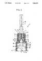
- FIG. 1is a view, in cross section, of the cylindrical hollow barrel with the needle holder body positioned in one end of the barrel,
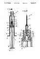
- FIG. 2 and FIG.3show the entire syringe in longitudinal, cross section.
- FIG. 2shows the piston within the barrel but spaced longitudinally or axially from the needle holder body while
- FIG. 3shows the piston in locked relationship with said body,
- FIGS. 4 and 5show details of the syringe on an enlarged basis
- FIG. 6shows the syringe with the needle withdrawn into the barrel
- FIG. 7shows a modified needle attachment means
- the reference numeral 1generally depicts the improved syringe and the reference numeral 2 designates the hollow cylindrical barrel member having first and second open ends.
- First female thread means 8are provided on the inside curved surface 7 of the first end of the hollow barrel.
- a cylindrically shaped needle holder body 4has a longitudinal axis and first and second axial ends and further comprises first male thread means 15 on the curved outer surface thereof which are adapted to coact with said first female thread means 8.
- the bodyalso has means on said first axial end thereof for receiving and holding an elongated hollow needle means, more specifically, an annular recess extending axially from the first axial end with second female thread means 13 disposed in the outer surface 14 of said annular recess.
- a standard holder 3 for a standard needle 11 and having a radially extending shoulder 12 at one end thereofis adapted to be threaded into the annular recess through the coaction of the shoulder 12 and the female threads 13.
- the second axial end of the bodyhas a first recess 17 extending longitudinally to a depth partway toward said first axial end of the body.
- the bodyhas a stoppage protrusion means in the form of an annular shoulder 16 extending radially inwardly in recess 17 toward the longitudinal axis as most clearly shown in FIG. 1.
- the shoulder 16extends around the body's longitudinal axis and is sloped from its inner tip toward the second open end of the barrel; the other surface of the protrusion is radially away from the longitudinal axis thus forming a shoulder which is normal to the longitudinal axis.
- the bodyhas a second recess in said second axial end extending along the longitudinal axis a depth less than the depth of recess 17 but having a greater radial extent measured from the longitudinal axis than recess 17.
- the bodyalso has a central bore 19 extending therethrough along the longitudinal axis.
- the bodyfurther has first rotational torque transmitting means 18 shown as longitudinal extending rib portions shown clearly in FIGS. 1, 2 and 4-7.
- the ribsextend radially toward the longitudinal axis a preselected distance and longitudinally a preselected distance.
- An elongated piston rod 5is provided consisting of a plurality of laterally extending flutes 24 emanating from the longitudinal axis and having at one end thereof an end piece 23 integral therewith so as to provide a means for moving the piston rod 5 in and out of the hollow barrel 2 along the longitudinal axis and further to permit the application of rotational torque to the piston rod by manual rotation of the piston (relative to the barrel about the longitudinal axis.
- a piston means 6is affixed to the other end of the piston rod 5; it has a generally circular cross-section and a relatively short axial or longitudinal extent thus defining an inner axial end which is adapted to be attached to or integral with the piston rod 5 and an outer axial end or face from which depends a centrally located axially extending protrusion, shown in all figures but expecially well (in phantom form) in FIG. 1, wherein it is seen that the said protrusion is shaped in a complementary form with respect to the recess 17 and its associated larger diameter recess including a circumferential groove 20 adapted to coact with annular shoulder 16.
- the piston 6further has a circumferencial flexible gasket 22 of a diameter selected so that when the piston 6 with the gasket 22 mounted thereon is positioned within the barrel 2, as shown in the figures, there will be a tight sliding fit between the piston assembly and the barrel to permit, when desired, the forcing or pumping of liquid within the barrel 2 out through the passageway 19 and the connected needle 11 or, in the other mode of operation, to pull fluid from an external source through the needle 11, passageway 19, and into the barrel 2.
- the piston assemblyfurther includes second rotational torque transmitting means 21 on said outer axial end of the piston 6 which are adapted to coact with said first rotational torque transmitting means 18.
- the specific means shownare a plurality of longitudinally extending and also radially inwardly extruding ribs arranged around the periphery of the piston assembly protrusion.
- the ribs 21are dimensioned to coact with the ribs 18 upon a preselected rotational relationship between the piston assembly 6 and the body 4; when this relationship is established, then the piston assembly may be moved axially toward the body so as to be in complete engagement with the body as is depicted in FIGS. 2-7. Once such total engagement is reached, the inwardly extending annular shoulder 16 will be "snapped" into position in the notch 20 of the piston assembly.
- the piston assemblyfurther includes a notch 25 in one or more of the fins or flutes 24 of the piston assembly; two such notches 25 are shown in FIGS. 2-7.
- the notches 25are adapted to coact with radially inwardly extending shoulders or latch means 9 with the cooperating surfaces being beveled to permit the piston assembly to move inwardly into the barrel 2 but the shoulder 9 serves as a latch by catching notches 25 to prevent the piston assembly from being withdrawn any further than the latch position as is depicted in FIG. 6 where the piston assembly, latched to the body 4 with the associated needle holder 3 and needle 11 has been withdrawn within the barrel a sufficient longitudinal extent so that the sharp pointed tip on the needle 11 is within the open end of the barrel.
- the barrel 2 and body 4would be preassembled at the factory; the piston assembly would also be, in the usual case, already positioned within the barrel 2 as shown in FIG. 2.
- the needle holder 3 and needle 11would be connected to the body 4 as is shown in FIGS. 2-7.
- the syringecan be used, as is well understood, either to inject fluid from within the syringe into a patient or to withdraw a fluid sample, e.g., blood, from a patient and collect it in the barrel.
- the piston assemblyUpon completion of the use of the syringe as intended, then in order to render the syringe safe from an accidental stick, the piston assembly is then forced longitudinally up into engagement with the body 4 by having the protrusion on the piston assembly placed into full engagement with the corresponding recess 17 of the body 4, all as aforesaid. In this position the firs and second rotational torque transmitting means 18 and 21 are in operative engagement so that, when rotational torque is applied to the handle piece 23 of the piston assembly of the correct sense, and the barrel 2 is held, then the body 4 is unthreaded and released from the barrel 2, the body 4 being carried along with the piston assembly due to the locking action of elements 16 with 20.
- the piston assemblymay be further moved in a longitudinal direction away from the first end of the barrel to a point where it is latched through the coaction between the shoulder 9 and the notches 25; at this point the dangerous sharp tip to the needle 11 is out of harms way by being completely within the first open end of the barrel member, an accidental contact of said point on the needle means by an errant body part being thus prevented.
- the reference numeral 26depicts a standard protective outer cap which may be used to safeguard the needle until actual use of the syringe is intended.
- FIG. 7shows an alternative embodiment wherein the needle holder 3 fits tightly on a central extension 27 of the body instead of coacting with the threads 13 on the inside surface 14 of the body 4, as described above.
- the preferred amount of threaded engagement between the male threads 15 on the body 4 and the female threaded portion 8 of the hollow barrel 2is approximately one-fourth to one turn. It may be assumed, by way of example, that it takes a relative clockwise rotation of the body 4 with respect to the barrel 2 to have the threaded engagement of the body with the barrel as is depicted, for example, in FIGS. 1-6.
Landscapes
- Health & Medical Sciences (AREA)
- Engineering & Computer Science (AREA)
- Heart & Thoracic Surgery (AREA)
- Vascular Medicine (AREA)
- Anesthesiology (AREA)
- Biomedical Technology (AREA)
- Environmental & Geological Engineering (AREA)
- Hematology (AREA)
- Life Sciences & Earth Sciences (AREA)
- Animal Behavior & Ethology (AREA)
- General Health & Medical Sciences (AREA)
- Public Health (AREA)
- Veterinary Medicine (AREA)
- Infusion, Injection, And Reservoir Apparatuses (AREA)
Abstract
Description
Claims (2)
Priority Applications (1)
| Application Number | Priority Date | Filing Date | Title |
|---|---|---|---|
| US07/973,556US5256151A (en) | 1989-06-15 | 1992-11-09 | Safety syringe with retractible needle holder |
Applications Claiming Priority (5)
| Application Number | Priority Date | Filing Date | Title |
|---|---|---|---|
| KR8290 | 1989-06-06 | ||
| KR2019890008290UKR910004532Y1 (en) | 1989-06-15 | 1989-06-15 | Syringe |
| US53824890A | 1990-08-30 | 1990-08-30 | |
| US88590392A | 1992-05-18 | 1992-05-18 | |
| US07/973,556US5256151A (en) | 1989-06-15 | 1992-11-09 | Safety syringe with retractible needle holder |
Related Parent Applications (1)
| Application Number | Title | Priority Date | Filing Date |
|---|---|---|---|
| US88590392AContinuation | 1989-06-15 | 1992-05-18 |
Publications (1)
| Publication Number | Publication Date |
|---|---|
| US5256151Atrue US5256151A (en) | 1993-10-26 |
Family
ID=27482874
Family Applications (1)
| Application Number | Title | Priority Date | Filing Date |
|---|---|---|---|
| US07/973,556Expired - Fee RelatedUS5256151A (en) | 1989-06-15 | 1992-11-09 | Safety syringe with retractible needle holder |
Country Status (1)
| Country | Link |
|---|---|
| US (1) | US5256151A (en) |
Cited By (30)
| Publication number | Priority date | Publication date | Assignee | Title |
|---|---|---|---|---|
| US5338304A (en)* | 1992-06-15 | 1994-08-16 | Adventec, Inc. | Needle protected syringe |
| US5415638A (en)* | 1988-12-14 | 1995-05-16 | Inviro Medical Devices, Ltd. | Safety syringe needle device with interchangeable and retractable needle platform |
| US5415646A (en)* | 1994-05-11 | 1995-05-16 | Roth; Noah M. | One use safety locking syringe |
| US5462531A (en)* | 1988-12-14 | 1995-10-31 | Inviro Medical Devices Ltd. | Safety syringe needle device with interchangeable and retractable needle platform |
| US5533970A (en)* | 1994-09-28 | 1996-07-09 | Becton, Dickinson And Company | Retractable needle syringe |
| AU675859B2 (en)* | 1993-08-06 | 1997-02-20 | Nihon Medi-Physics Co., Ltd. | Luer needle unit and injector |
| WO1997006841A1 (en)* | 1995-08-14 | 1997-02-27 | Vista Medical Innovations, Incorporated | Protractable and retractable hypodermic needle syringe |
| US5658257A (en)* | 1991-04-17 | 1997-08-19 | Medical Plastics (Aust) Pty. Ltd. | Syringe |
| US5902269A (en)* | 1996-11-26 | 1999-05-11 | Jentzen; S. William | Low dead space, interchangeable needle syringe |
| US5968019A (en)* | 1998-07-14 | 1999-10-19 | Tun Huang International Development And Investment Co., Ltd. | Safety syringe |
| US5968020A (en)* | 1993-03-12 | 1999-10-19 | Saito; Yoshikuni | Syringe assembly |
| US5980487A (en)* | 1994-05-04 | 1999-11-09 | Product Research Limited | Hypodermic syringe |
| WO1999062575A3 (en)* | 1998-06-01 | 2000-02-03 | Inviro Medical Devices Ltd | Safety syringe with retractable needle and universal luer coupling |
| US6033386A (en)* | 1988-12-14 | 2000-03-07 | Inviro Medical Devices, Ltd. | Safety syringe needle device with interchangeable and retractable needle platform |
| WO2001007106A1 (en)* | 1999-07-27 | 2001-02-01 | Medi Plus Tec Medizinisch-Technische Handelsgesel Lschaft Mbh | Safety syringe |
| US6342045B1 (en)* | 1997-05-26 | 2002-01-29 | Brice Somers | Safety syringe |
| US6344031B1 (en) | 1989-03-22 | 2002-02-05 | Laurel A. Novacek | Safety syringe needle device with interchangeable and retractable needle platform |
| WO2002022194A1 (en)* | 2000-07-25 | 2002-03-21 | Hsieh, Hsien-Ming | A self-destructing syringe |
| US6530903B2 (en) | 2000-02-24 | 2003-03-11 | Xiping Wang | Safety syringe |
| US20030212366A1 (en)* | 2002-05-07 | 2003-11-13 | Young Chul Bang | Safety syringe |
| US6656165B2 (en)* | 2001-10-26 | 2003-12-02 | Hsin Cheng Chen | Disposable safety syringe |
| GB2420713A (en)* | 2004-12-01 | 2006-06-07 | Jih-Hsiung Yang | Safe syringe |
| US20070016145A1 (en)* | 2005-06-09 | 2007-01-18 | Devon Safety Products, Inc. | Needle assembly for multiple syringe barrels |
| US20070078390A1 (en)* | 2005-08-31 | 2007-04-05 | U-Conn Technology Inc. | Injection syringe |
| WO2007112470A1 (en) | 2006-04-06 | 2007-10-11 | Pharma Consult Ges.M.B.H & Co Nfg Kg | Injection syringe |
| US20080097314A1 (en)* | 2006-08-08 | 2008-04-24 | Jih-Hsiung Yang | Safety syringe |
| GB2445733A (en)* | 2006-08-15 | 2008-07-23 | David Alan Halfpenny | Medical syringe |
| US20110046561A1 (en)* | 2008-02-07 | 2011-02-24 | Brigitte Pickhard | Injection syringe |
| US8057431B2 (en) | 2006-12-21 | 2011-11-15 | B. Braun Melsungen Ag | Hinged cap for needle device |
| US20170158413A1 (en)* | 2012-11-08 | 2017-06-08 | Sulzer Mixpac Ag | Cartridge for at least two flowable components |
Citations (23)
| Publication number | Priority date | Publication date | Assignee | Title |
|---|---|---|---|---|
| US3890971A (en)* | 1973-10-23 | 1975-06-24 | Thomas A Leeson | Safety syringe |
| US4026287A (en)* | 1975-12-10 | 1977-05-31 | Irene Haller | Syringe with retractable cannula |
| US4391272A (en)* | 1978-03-10 | 1983-07-05 | Tulcea, S.A. | Disposable syringe |
| US4507117A (en)* | 1983-07-11 | 1985-03-26 | Vining Herbert C | Syringe apparatus with retractable needle |
| US4650468A (en)* | 1986-02-26 | 1987-03-17 | Jennings Jr Baldwin P | Medical syringe |
| US4675005A (en)* | 1986-05-08 | 1987-06-23 | Deluccia James | Retractable disposable syringe |
| US4710170A (en)* | 1987-02-12 | 1987-12-01 | Habley Medical Technology Corporation | Anti-needle strike and anti-drug abuse syringe |
| US4743233A (en)* | 1986-01-23 | 1988-05-10 | Schneider Medical Technologies, Inc. | Safety cap syringe |
| US4747830A (en)* | 1986-04-28 | 1988-05-31 | Gloyer Walter W | Anti-stick contagion free disposable hypodermic safety syringe |
| US4752290A (en)* | 1987-07-27 | 1988-06-21 | Schramm James J | Needle bearing medical device with three-position shield |
| US4781684A (en)* | 1987-09-03 | 1988-11-01 | Trenner Lewis E | Single use disposable hypodermic syringe |
| US4861338A (en)* | 1988-02-11 | 1989-08-29 | Mediverse Inc. | Safety syringe |
| US4888002A (en)* | 1988-08-30 | 1989-12-19 | Braginetz Paul A | Disposable shield medical syringe |
| US4932939A (en)* | 1989-03-06 | 1990-06-12 | Magre George R | Safety syringe |
| US4950243A (en)* | 1987-11-27 | 1990-08-21 | Estruch Miracle C | Syringe for one sole use |
| US4950241A (en)* | 1988-12-27 | 1990-08-21 | Sherwood Medical Company | Disposable syringe |
| US4955869A (en)* | 1988-02-04 | 1990-09-11 | Vabin International S.R.L. | Disposable safety syringe with a hypodermic needle |
| US4978340A (en)* | 1988-06-15 | 1990-12-18 | Alteron Incorporated | Syringe with retractable needle |
| US4986813A (en)* | 1988-02-01 | 1991-01-22 | The MadTech Group, Inc. | Disposable hypodermic syringe |
| US4995874A (en)* | 1989-06-23 | 1991-02-26 | Strickland H Allen | Disposable syringe device |
| US5019043A (en)* | 1988-08-05 | 1991-05-28 | Vincent Miguel Segui Pastor | Syringe with needle retraction capability |
| US5030208A (en)* | 1989-03-22 | 1991-07-09 | Novacek Laurel A | Safety syringe needle device with interchangeable and retractable needle platform |
| US5141500A (en)* | 1989-03-02 | 1992-08-25 | Lawrence W. Hake | Hypodermic needle guard |
- 1992
- 1992-11-09USUS07/973,556patent/US5256151A/ennot_activeExpired - Fee Related
Patent Citations (24)
| Publication number | Priority date | Publication date | Assignee | Title |
|---|---|---|---|---|
| US3890971A (en)* | 1973-10-23 | 1975-06-24 | Thomas A Leeson | Safety syringe |
| US4026287A (en)* | 1975-12-10 | 1977-05-31 | Irene Haller | Syringe with retractable cannula |
| US4391272A (en)* | 1978-03-10 | 1983-07-05 | Tulcea, S.A. | Disposable syringe |
| US4507117B1 (en)* | 1983-07-11 | 1988-06-21 | ||
| US4507117A (en)* | 1983-07-11 | 1985-03-26 | Vining Herbert C | Syringe apparatus with retractable needle |
| US4743233A (en)* | 1986-01-23 | 1988-05-10 | Schneider Medical Technologies, Inc. | Safety cap syringe |
| US4650468A (en)* | 1986-02-26 | 1987-03-17 | Jennings Jr Baldwin P | Medical syringe |
| US4747830A (en)* | 1986-04-28 | 1988-05-31 | Gloyer Walter W | Anti-stick contagion free disposable hypodermic safety syringe |
| US4675005A (en)* | 1986-05-08 | 1987-06-23 | Deluccia James | Retractable disposable syringe |
| US4710170A (en)* | 1987-02-12 | 1987-12-01 | Habley Medical Technology Corporation | Anti-needle strike and anti-drug abuse syringe |
| US4752290A (en)* | 1987-07-27 | 1988-06-21 | Schramm James J | Needle bearing medical device with three-position shield |
| US4781684A (en)* | 1987-09-03 | 1988-11-01 | Trenner Lewis E | Single use disposable hypodermic syringe |
| US4950243A (en)* | 1987-11-27 | 1990-08-21 | Estruch Miracle C | Syringe for one sole use |
| US4986813A (en)* | 1988-02-01 | 1991-01-22 | The MadTech Group, Inc. | Disposable hypodermic syringe |
| US4955869A (en)* | 1988-02-04 | 1990-09-11 | Vabin International S.R.L. | Disposable safety syringe with a hypodermic needle |
| US4861338A (en)* | 1988-02-11 | 1989-08-29 | Mediverse Inc. | Safety syringe |
| US4978340A (en)* | 1988-06-15 | 1990-12-18 | Alteron Incorporated | Syringe with retractable needle |
| US5019043A (en)* | 1988-08-05 | 1991-05-28 | Vincent Miguel Segui Pastor | Syringe with needle retraction capability |
| US4888002A (en)* | 1988-08-30 | 1989-12-19 | Braginetz Paul A | Disposable shield medical syringe |
| US4950241A (en)* | 1988-12-27 | 1990-08-21 | Sherwood Medical Company | Disposable syringe |
| US5141500A (en)* | 1989-03-02 | 1992-08-25 | Lawrence W. Hake | Hypodermic needle guard |
| US4932939A (en)* | 1989-03-06 | 1990-06-12 | Magre George R | Safety syringe |
| US5030208A (en)* | 1989-03-22 | 1991-07-09 | Novacek Laurel A | Safety syringe needle device with interchangeable and retractable needle platform |
| US4995874A (en)* | 1989-06-23 | 1991-02-26 | Strickland H Allen | Disposable syringe device |
Cited By (44)
| Publication number | Priority date | Publication date | Assignee | Title |
|---|---|---|---|---|
| US6033386A (en)* | 1988-12-14 | 2000-03-07 | Inviro Medical Devices, Ltd. | Safety syringe needle device with interchangeable and retractable needle platform |
| US5415638A (en)* | 1988-12-14 | 1995-05-16 | Inviro Medical Devices, Ltd. | Safety syringe needle device with interchangeable and retractable needle platform |
| US6117113A (en)* | 1988-12-14 | 2000-09-12 | Inviro Medical Devices Ltd. | Safety syringe needle device with interchangeable and retractable needle platform |
| US5462531A (en)* | 1988-12-14 | 1995-10-31 | Inviro Medical Devices Ltd. | Safety syringe needle device with interchangeable and retractable needle platform |
| US5520649A (en)* | 1988-12-14 | 1996-05-28 | Inviro Medical Devices Ltd. | Safety syringe needle device with interchangeable and retractable needle platform |
| US6878131B2 (en) | 1988-12-14 | 2005-04-12 | Inviro Medical Devices, Ltd. | Safety syringe needle device with interchangeable and retractable needle platform |
| US20050192541A1 (en)* | 1988-12-14 | 2005-09-01 | Inviro Medical Devices Limited | Safety syringe needle device with interchangeable and retractable needle platform |
| US6344031B1 (en) | 1989-03-22 | 2002-02-05 | Laurel A. Novacek | Safety syringe needle device with interchangeable and retractable needle platform |
| US5658257A (en)* | 1991-04-17 | 1997-08-19 | Medical Plastics (Aust) Pty. Ltd. | Syringe |
| US5338304A (en)* | 1992-06-15 | 1994-08-16 | Adventec, Inc. | Needle protected syringe |
| US5968020A (en)* | 1993-03-12 | 1999-10-19 | Saito; Yoshikuni | Syringe assembly |
| US5611785A (en)* | 1993-08-06 | 1997-03-18 | Nihon Medi-Physics Co., Ltd. | Luer needle unit and injector |
| AU675859B2 (en)* | 1993-08-06 | 1997-02-20 | Nihon Medi-Physics Co., Ltd. | Luer needle unit and injector |
| US5980487A (en)* | 1994-05-04 | 1999-11-09 | Product Research Limited | Hypodermic syringe |
| US5415646A (en)* | 1994-05-11 | 1995-05-16 | Roth; Noah M. | One use safety locking syringe |
| US5533970A (en)* | 1994-09-28 | 1996-07-09 | Becton, Dickinson And Company | Retractable needle syringe |
| WO1997006841A1 (en)* | 1995-08-14 | 1997-02-27 | Vista Medical Innovations, Incorporated | Protractable and retractable hypodermic needle syringe |
| US5902269A (en)* | 1996-11-26 | 1999-05-11 | Jentzen; S. William | Low dead space, interchangeable needle syringe |
| US6342045B1 (en)* | 1997-05-26 | 2002-01-29 | Brice Somers | Safety syringe |
| WO1999062575A3 (en)* | 1998-06-01 | 2000-02-03 | Inviro Medical Devices Ltd | Safety syringe with retractable needle and universal luer coupling |
| US6183464B1 (en) | 1998-06-01 | 2001-02-06 | Inviro Medical Devices Ltd. | Safety syringe with retractable needle and universal luer coupling |
| US5968019A (en)* | 1998-07-14 | 1999-10-19 | Tun Huang International Development And Investment Co., Ltd. | Safety syringe |
| WO2001007106A1 (en)* | 1999-07-27 | 2001-02-01 | Medi Plus Tec Medizinisch-Technische Handelsgesel Lschaft Mbh | Safety syringe |
| US6530903B2 (en) | 2000-02-24 | 2003-03-11 | Xiping Wang | Safety syringe |
| GB2381199A (en)* | 2000-07-25 | 2003-04-30 | Hsien-Ming Hsieh | A self-destructing syringe |
| WO2002022194A1 (en)* | 2000-07-25 | 2002-03-21 | Hsieh, Hsien-Ming | A self-destructing syringe |
| US6656165B2 (en)* | 2001-10-26 | 2003-12-02 | Hsin Cheng Chen | Disposable safety syringe |
| US6706015B2 (en)* | 2002-05-07 | 2004-03-16 | Medexel Korea | Safety syringe |
| US20030212366A1 (en)* | 2002-05-07 | 2003-11-13 | Young Chul Bang | Safety syringe |
| GB2420713A (en)* | 2004-12-01 | 2006-06-07 | Jih-Hsiung Yang | Safe syringe |
| GB2420713B (en)* | 2004-12-01 | 2007-12-19 | Jih-Hsiung Yang | Safe syringe |
| US20070016145A1 (en)* | 2005-06-09 | 2007-01-18 | Devon Safety Products, Inc. | Needle assembly for multiple syringe barrels |
| US20070078390A1 (en)* | 2005-08-31 | 2007-04-05 | U-Conn Technology Inc. | Injection syringe |
| US20090312703A1 (en)* | 2006-04-06 | 2009-12-17 | Pharma Consult Ges.M.B.H & Co Nfg Kg | Injection Syringe |
| WO2007112470A1 (en) | 2006-04-06 | 2007-10-11 | Pharma Consult Ges.M.B.H & Co Nfg Kg | Injection syringe |
| US8105293B2 (en) | 2006-04-06 | 2012-01-31 | Pharma Consult Ges.M.B.H & Co Nfg Kg | Injection syringe |
| US20080097314A1 (en)* | 2006-08-08 | 2008-04-24 | Jih-Hsiung Yang | Safety syringe |
| GB2445733B (en)* | 2006-08-15 | 2011-04-27 | David Alan Halfpenny | Medical syringe |
| GB2445733A (en)* | 2006-08-15 | 2008-07-23 | David Alan Halfpenny | Medical syringe |
| US8057431B2 (en) | 2006-12-21 | 2011-11-15 | B. Braun Melsungen Ag | Hinged cap for needle device |
| US8715231B2 (en) | 2006-12-21 | 2014-05-06 | B. Braun Melsungen Ag | Hinged cap for needle device |
| US20110046561A1 (en)* | 2008-02-07 | 2011-02-24 | Brigitte Pickhard | Injection syringe |
| US8728042B2 (en) | 2008-02-07 | 2014-05-20 | Pharma Consult Ges.M.B.H. | Injection syringe |
| US20170158413A1 (en)* | 2012-11-08 | 2017-06-08 | Sulzer Mixpac Ag | Cartridge for at least two flowable components |
Similar Documents
| Publication | Publication Date | Title |
|---|---|---|
| US5256151A (en) | Safety syringe with retractible needle holder | |
| EP0463086B1 (en) | Syringe with interchangeable and retractable needle platform | |
| US5122124A (en) | Safety syringe needle device with interchangeable and retractable needle platform | |
| US4592744A (en) | Self-resheathing needle assembly | |
| US5342309A (en) | Syringe having safety shield | |
| US5009642A (en) | Self-blunting needle assembly for use with a catheter, and catheter assembly using the same | |
| EP0566305B1 (en) | Safety needle syringe | |
| US5112318A (en) | Safety syringe needle device with interchangeable and retractable needle platform | |
| US5688240A (en) | Safety syringe needle device with interchangeable and retractable needle platform | |
| FI106536B (en) | Injection syringe | |
| US4874384A (en) | Needle safety guard | |
| US5273543A (en) | Safety needle syringe | |
| US4692156A (en) | Disposable syringe with retractable cannula | |
| US4846811A (en) | Sliding sheath for medical needles | |
| US4861338A (en) | Safety syringe | |
| US5501670A (en) | Syringe system providing retraction of needle cannula into disposable cartridge | |
| US6033386A (en) | Safety syringe needle device with interchangeable and retractable needle platform | |
| EP1092445B1 (en) | Improved syringe plunger rod for retracting needle syringe | |
| US5205827A (en) | Safety syringe needle device with interchangeable and retractable needle platform | |
| US4631057A (en) | Shielded needle | |
| US5263933A (en) | Safety syringe needle device with interchangeable and retractable needle platform | |
| EP0681487B1 (en) | Hypodermic syringe with needle retraction feature | |
| EP1075850B1 (en) | Apparatus for intravenous catheter insertion | |
| JPH08107931A (en) | Syringe | |
| US5415638A (en) | Safety syringe needle device with interchangeable and retractable needle platform |
Legal Events
| Date | Code | Title | Description |
|---|---|---|---|
| AS | Assignment | Owner name:MMCT HOLDINGS, WYOMING Free format text:ASSIGNMENT OF ASSIGNORS INTEREST;ASSIGNOR:MEDIVERSE, INC.;REEL/FRAME:007022/0146 Effective date:19940531 | |
| AS | Assignment | Owner name:BANK OF NEW YORK, AS AGENT, THE, NEW YORK Free format text:SECURITY INTEREST;ASSIGNOR:GENERAL DATACOMM, INC.;REEL/FRAME:007030/0214 Effective date:19940601 | |
| AS | Assignment | Owner name:LIBERTY STATE BANK, MINNESOTA Free format text:SECURITY INTEREST;ASSIGNOR:MMCT HOLDINGS, LLC;REEL/FRAME:007203/0531 Effective date:19941031 | |
| AS | Assignment | Owner name:MMCT HOLDINGS, LLC, WYOMING Free format text:CORRECTIV;ASSIGNOR:MEDIVERSE, INC.;REEL/FRAME:007541/0476 Effective date:19940531 | |
| FPAY | Fee payment | Year of fee payment:4 | |
| REMI | Maintenance fee reminder mailed | ||
| REIN | Reinstatement after maintenance fee payment confirmed | ||
| FP | Lapsed due to failure to pay maintenance fee | Effective date:20011026 | |
| FEPP | Fee payment procedure | Free format text:PETITION RELATED TO MAINTENANCE FEES FILED (ORIGINAL EVENT CODE: PMFP); ENTITY STATUS OF PATENT OWNER: SMALL ENTITY Free format text:PETITION RELATED TO MAINTENANCE FEES GRANTED (ORIGINAL EVENT CODE: PMFG); ENTITY STATUS OF PATENT OWNER: SMALL ENTITY | |
| FPAY | Fee payment | Year of fee payment:8 | |
| SULP | Surcharge for late payment | ||
| PRDP | Patent reinstated due to the acceptance of a late maintenance fee | Effective date:20031027 | |
| REMI | Maintenance fee reminder mailed | ||
| LAPS | Lapse for failure to pay maintenance fees | ||
| STCH | Information on status: patent discontinuation | Free format text:PATENT EXPIRED DUE TO NONPAYMENT OF MAINTENANCE FEES UNDER 37 CFR 1.362 | |
| FP | Lapsed due to failure to pay maintenance fee | Effective date:20051026 |