US5255890A - Ram type blowout preventer - Google Patents
Ram type blowout preventerDownload PDFInfo
- Publication number
- US5255890A US5255890AUS08/017,314US1731493AUS5255890AUS 5255890 AUS5255890 AUS 5255890AUS 1731493 AUS1731493 AUS 1731493AUS 5255890 AUS5255890 AUS 5255890A
- Authority
- US
- United States
- Prior art keywords
- bonnet
- metal ring
- end wall
- ring
- preventer
- Prior art date
- Legal status (The legal status is an assumption and is not a legal conclusion. Google has not performed a legal analysis and makes no representation as to the accuracy of the status listed.)
- Ceased
Links
Images

Classifications
- E—FIXED CONSTRUCTIONS
- E21—EARTH OR ROCK DRILLING; MINING
- E21B—EARTH OR ROCK DRILLING; OBTAINING OIL, GAS, WATER, SOLUBLE OR MELTABLE MATERIALS OR A SLURRY OF MINERALS FROM WELLS
- E21B33/00—Sealing or packing boreholes or wells
- E21B33/02—Surface sealing or packing
- E21B33/03—Well heads; Setting-up thereof
- E21B33/06—Blow-out preventers, i.e. apparatus closing around a drill pipe, e.g. annular blow-out preventers
- E21B33/061—Ram-type blow-out preventers, e.g. with pivoting rams
- E21B33/062—Ram-type blow-out preventers, e.g. with pivoting rams with sliding rams
Definitions
- This inventionrelates generally to blowout preventers for closing about a pipe or other objects in the bore or across an open bore of a housing mounted on a wellhead. More particularly, it relates to improvements in ram type blowout preventers wherein rams are slidable within guideways extending radially from the bore between inner positions to engage one another to close the bore and outer positions to open the bore.
- bonnetsare mounted on the body for movement between positions opening and closing the outer ends of the guideways to permit the rams to be installed within or removed from the guideways.
- Hydraulic operators mounted on the bonnetsinclude a rod extending through the bonnet for connection with the rams.
- the bonnetsmay be hinged to the body for swinging between opened and closed positions, or they may be so moved by the hydraulic operators. In either case, the inner faces of the bonnets are forced into tight engagement with the outer faces of the body by bolts connecting the bonnet to the body.
- Packingsare carried on the inner face of the bonnet to sealably engage the outer face of the body in an effort to contain the fluid pressure in the preventer bore, and thus in the guideways.
- neither faceis perfectly flat so that there are gaps between them even when forced against one another as the bolts are made up.
- the fluid pressure in the preventermay be so high as to cause the bonnet to bend outwardly, thus tending to create even greater gaps between the faces into which the packing may extrude, in addition to those gaps which normally result from deflection of the bolts due to the internal pressure, whereby the large gaps which occur because of deflection are very difficult to seal under conditions of high/low temperatures and high pressure.
- the object of this inventionis to provide a ram type blowout preventer of the type described in which the body and bonnet faces are so sealed with respect to one another as to overcome these and other problems; and, more particularly, to provide such a preventer having means for sealing between the faces which is of such construction as to eliminate gaps between the faces of the bonnet and body through which leaks might occur without having to overtorque the bolts.
- a ram type blowout preventor of the type describedin which the bonnet has a recess in its inner face to form a peripheral wall and an end wall opposite the outer face of the body when the bonnet is closed, and a metal ring mounted on the bonnet for limited axial and radial movement within the recess carries a first elastomeric ring on its inner side for sealing against the face of the body.
- Meanssuch as a spring acts between the inner wall of the recess and the metal ring to yieldably urge the inner side of the metal ring toward said outer face of the bonnet, and a second elastomeric ring is carried about the outer periphery of the metal ring for sealing against the peripheral wall of the recess about an area which is greater than the area of the sealing engagement of the first elastomeric ring with the bonnet face and spaced outwardly therefrom, whereby fluid pressure in the guideway is effective to urge the metal ring toward the outer bonnet face and at the same time expand its outer circumference toward said peripheral wall of the recess.
- the metal ringis of such construction that its inner side is tightly engaged against the outer face of the body prior to radial expansion of the ring periphery thereof and tightly against the peripheral wall of the recess, thus assuring that gaps between the body and bonnet surfaces are closed to prevent extrusion of the elastomeric rings between them.
- the metal ringhas holes extending therethrough from its inner to its outer sides, and bolts extend loosely through the holes and into the end wall of the recess and have enlarged outer ends to retain the metal ring on the bonnet while permitting it to move limited distances radially as well as axially of the bolts.
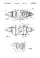
- FIG. 1is a side view of a blowout preventer constructed in accordance with the preferred embodiment of the invention and with its left end in elevation and right end in vertical section, and showing the bonnets closed and at least the right-hand ram withdrawn to its open position;
- FIG. 2is a top view of the preventer, as seen along broken lines 2--2 of FIG. 1, and with its left end in plan and its right end partly broken away;
- FIG. 3is a view of the end of the preventer, as seen along broken lines 3--3 of FIG. 1;
- FIG. 4is a somewhat enlarged cross-sectional view of the preventer, as seen along broken lines 4--4 of FIG. 1;
- FIG. 5is an enlarged cross-sectional view of a part of the preventer indicated by the circle "5" of FIG. 1, and showing the details of the assembly which seals between the body and bonnet faces.
- the overall preventerwhich is indicated in its entirety by reference character 20, comprises a body 21 having a bore 22 therethrough and means such as a flange on its lower end, so that as well-known in the art, it may be installed on the upper end of a wellhead to form an upper continuation of the bore through the wellhead and thus to receive pipe, such as drill pipe, as it is being lowered into or raised from within the wellhead and thus the well therebelow.
- the bodyalso has guideways 23 extending from its bore and through the body generally radially opposite one another (only the right-hand guideway being shown in FIGS. 1 and 2), and a ram 24 is slidable within each guideway for movement between an inner position in which its inner end engages the inner end of another ram, and an outer position, as shown in FIGS. 1 and 2, wherein it opens the bore.
- the ramshave recesses on their inner ends for fitting closely about a pipe within the bore, and carry seal members across its front face and along the opposite sides and over the top of the ram for sealing with respect to a pipe in the bore and an opposed ram as well as with respect to the guideway in the preventer body when the rams are closed.
- each guidewayis adapted to be opened and closed by means of a bonnet 25 releasably connected to the body by means of threaded bolts 26.
- a bonnet 25releasably connected to the body by means of threaded bolts 26.
- its inner face 27is sealed with respect to an outer face 28 on the body which surrounds the outer end of the guideway 23 so as to contain fluid pressure within the preventer.
- the ramsare adapted to be moved between open and closed positions by operating means including a cylinder 29 mounted on the outer side of the bonnet 25, and a piston 30 sealably reciprocal in the cylinder and having a rod 31 which extends through a hole in the bonnet to connect with the ram 24.
- hydraulic fluidmay be selectively introduced to and exhausted from opposite sides of the piston 30 in the cylinder 29 for selectively moving the ram between its open and closed positions.
- a hinge 32connects the bonnet to the body for swinging about hinge pin 33 between open and closed positions when it has been disconnected from the body by backing off the bolts 26.
- the outer end of the guidewaywould be suitably enlarged to permit the ram to move freely into and out of the guideway when the ram is in its outer open position.
- the preventer bodyis of generally square construction, while the bonnet 25 is more rectangular due primarily to its lesser height. Thus, as shown in these figures, there is no room for bolts 26 along the top and bottom of the bonnet.
- each bonnethas an annular recess formed therein which, as shown, is cylindrical, but which may be of other configuration, such as oval.
- the recesshas a peripheral wall 34 and an end wall 35 which is opposite the outer face 21A of the preventer body, and a seal assembly, including a metal ring 36, is mounted in the recess for limited axial and radial movement within the recess. More particularly, the assembly also includes a first elastomeric ring 37 which is received in a groove about the inner side of the metal ring for engaging the outer face 21A of the body.
- the seal ringis an O-ring having a diameter greater than the depth of the recess so as to protrude therefrom, and a wavy spring 39 is received within a groove 41 about the outer side of the metal ring in position to be axially compressed between the bottom of the groove and the end wall 35 of the bonnet recess, whereby the metal ring is urged inwardly toward the body face 21A so as to compress the seal ring 37 between the face and bottom of the groove in the metal ring.
- the assemblyalso includes another elastomeric seal ring 40 which is received in a groove 41 about the outer circumference of the metal ring opposite the peripheral wall 34 of the recess.
- this ring 40is also an O-ring and has a diameter greater than the depth of the groove 41 so as to protrude therefrom and thus sealably engage the wall 34.
- seal rings 37 and 40may be other than O-rings, such as lips arranged to face the internal pressure.
- means other than the wavy spring 39, such as an O-ringmay be compressed axially between the groove and end wall of the recess, may be used to initially urge the inner side of the metal ring against the outer face 21A.
- the O-ring 40sealably engages the peripheral wall of the recess about an area greater than the area with which the seal ring 37 sealably engages the face 21A of the preventer body.
- fluid pressure in the guideway of the preventeris effective to urge the metal ring inwardly against the face 21A with a force equal to that pressure times an annular area equal to the difference between the outer diameter of the O-ring 40 and the sealing diameter of the seal ring 38.
- the metal ringis urged radially outwardly toward the wall 34 by a force equal to the internal pressure times an annular area intermediate the sealing engagement of the O-ring 37 with the face 21A and the sealing engagement of the O-ring 40 with the wall 34.
- the ringis of such size and shape that the internal pressure will force the inner side of the metal ring tightly against the outer face of the body prior to radial expansion of its periphery against the peripheral wall of the recess.
- the metal ringshould not be so thin relative to its length as to be too stiff in an axial direction to conform to the outer face of the preventer body, or to lack sufficient stiffness radially to cause its outer periphery to engage the peripheral wall of the recess too soon and thus lock it within the recess prior to axial movement of its inner side against the face 21A of the body.
- the metal ringshould not be so thick in a radial direction as to prevent its outer periphery from conforming to the peripheral wall, following conforming of its inner side against the outer face of the body, so as to close gaps through which seal ring 40 might extrude.
- the areas A f and A oare respectively the unbalanced area of the seal face of the ring and the unbalanced area about the outer periphery of the ring.
- the minimum area A o for a given A fmay be calculated in accordance with the following equations, wherein:
- P cInternal Blowout Pressure at which ring is expanded to close the gap (The gap is usually 0.005" or more with the ring at rest.)
- the force required to expand the ring into contact with the peripheral surface of the cavityequals P c (A o ), and the sum of forces F o in the radial direction is P(A o )-P c (A o ), wherein, as above noted, F o is the reaction to the pressure-induced force of the ring on the peripheral wall upon contact.
- the metal ring 36is mounted on the bonnet by a pair of spaced-apart bolts 42 which extend through holes 43 in the ring and which are threadedly connected at their inner ends to threaded sockets in the end wall of the recess. As shown, the holes 43 are substantially larger than the diameters of the bolts 42 so as to permit limited radial movement of the metal ring with respect to the bolts, as may be necessary to enable the metal ring to be forced radially outwardly by internal pressure, as previously described.
- the metal ringis retained on the bonnet by an enlarged head 44 received in a recess 45 on the inner side of the metal ring.
- the heads 44are larger than the holes 43.
Landscapes
- Life Sciences & Earth Sciences (AREA)
- Engineering & Computer Science (AREA)
- Geology (AREA)
- Mining & Mineral Resources (AREA)
- Physics & Mathematics (AREA)
- Environmental & Geological Engineering (AREA)
- Fluid Mechanics (AREA)
- General Life Sciences & Earth Sciences (AREA)
- Geochemistry & Mineralogy (AREA)
- Gasket Seals (AREA)
Abstract
Description
F.sub.f =P.sub.c (A.sub.f)
P.sub.f =μ(P.sub.c),
P.sub.c =P.sub.e +μ(P.sub.c)
P.sub.c =P.sub.e /(1-μ).
P(A.sub.f)=N(μ)(F.sub.o)
P(A.sub.o)=P(A.sub.f)/N(μ)+P.sub.c (A.sub.o).
A.sub.f /A.sub.o =N(μ)(1-P.sub.c /P)
Claims (4)
Priority Applications (5)
| Application Number | Priority Date | Filing Date | Title |
|---|---|---|---|
| US08/017,314US5255890A (en) | 1992-11-12 | 1993-02-11 | Ram type blowout preventer |
| DE69306537TDE69306537T2 (en) | 1992-11-12 | 1993-10-25 | Jaw blow-out preventer with improved seal |
| EP93117250AEP0597306B1 (en) | 1992-11-12 | 1993-10-25 | Ram type blowout preventer with improved seal |
| NO933836ANO303881B1 (en) | 1992-11-12 | 1993-10-25 | Exhaust type shut-off type |
| US08/548,201USRE37538E1 (en) | 1992-11-12 | 1995-10-25 | Ram type blowout preventer |
Applications Claiming Priority (2)
| Application Number | Priority Date | Filing Date | Title |
|---|---|---|---|
| US97527192A | 1992-11-12 | 1992-11-12 | |
| US08/017,314US5255890A (en) | 1992-11-12 | 1993-02-11 | Ram type blowout preventer |
Related Parent Applications (1)
| Application Number | Title | Priority Date | Filing Date |
|---|---|---|---|
| US97527192AContinuation | 1992-11-12 | 1992-11-12 |
Related Child Applications (1)
| Application Number | Title | Priority Date | Filing Date |
|---|---|---|---|
| US08/548,201ReissueUSRE37538E1 (en) | 1992-11-12 | 1995-10-25 | Ram type blowout preventer |
Publications (1)
| Publication Number | Publication Date |
|---|---|
| US5255890Atrue US5255890A (en) | 1993-10-26 |
Family
ID=26689714
Family Applications (2)
| Application Number | Title | Priority Date | Filing Date |
|---|---|---|---|
| US08/017,314CeasedUS5255890A (en) | 1992-11-12 | 1993-02-11 | Ram type blowout preventer |
| US08/548,201Expired - LifetimeUSRE37538E1 (en) | 1992-11-12 | 1995-10-25 | Ram type blowout preventer |
Family Applications After (1)
| Application Number | Title | Priority Date | Filing Date |
|---|---|---|---|
| US08/548,201Expired - LifetimeUSRE37538E1 (en) | 1992-11-12 | 1995-10-25 | Ram type blowout preventer |
Country Status (4)
| Country | Link |
|---|---|
| US (2) | US5255890A (en) |
| EP (1) | EP0597306B1 (en) |
| DE (1) | DE69306537T2 (en) |
| NO (1) | NO303881B1 (en) |
Cited By (21)
| Publication number | Priority date | Publication date | Assignee | Title |
|---|---|---|---|---|
| WO1996021795A1 (en)* | 1995-01-13 | 1996-07-18 | Hydril Company | Low profile and lightweight high pressure blowout preventer |
| FR2757895A1 (en) | 1996-12-27 | 1998-07-03 | Varco Shaffer Inc | WELL SHUTTER BLOCK USEFUL IN THE RECOVERY OF HYDROCARBONS AND ITS IMPLEMENTING METHOD |
| WO1998053228A1 (en)* | 1997-05-21 | 1998-11-26 | Allison Advanced Development Company | Interstage vane seal apparatus |
| USRE37538E1 (en) | 1992-11-12 | 2002-02-05 | Hydril Company | Ram type blowout preventer |
| WO2002090708A1 (en) | 2001-05-04 | 2002-11-14 | Hydril Company | Rotational mounts for blowout preventer bonnets |
| WO2002090709A2 (en) | 2001-05-04 | 2002-11-14 | Hydril Company | Quick release blowout preventer bonnet |
| EP1473436A2 (en) | 2003-04-28 | 2004-11-03 | Hydril Company | Quick release blowout preventer bonnet |
| US20050242308A1 (en)* | 2004-05-01 | 2005-11-03 | Gaydos Stephen T | Blowout preventer and ram actuator |
| US20060000992A1 (en)* | 2004-07-01 | 2006-01-05 | Springett Frank B | Blowout preventer and movable bonnet support |
| US20080265188A1 (en)* | 2007-04-27 | 2008-10-30 | Frank Benjamin Springett | Ram locking blowout preventer |
| US7699554B2 (en) | 2003-06-03 | 2010-04-20 | Hydril Usa Manufacturing Llc | Removable seal carrier for blowout preventer bonnet assembly |
| CN101748986A (en)* | 2008-12-18 | 2010-06-23 | 海德里尔美国制造业有限责任公司 | Bidirectional flashboard BOP and method |
| US8229605B2 (en) | 2010-05-13 | 2012-07-24 | Embedded Control Systems Inc. | Aviation application setting antenna array and integrated temperature sensor |
| CN102628344A (en)* | 2011-02-02 | 2012-08-08 | 海德里尔美国制造业有限责任公司 | Shear blade geometry and method |
| US8540017B2 (en) | 2010-07-19 | 2013-09-24 | National Oilwell Varco, L.P. | Method and system for sealing a wellbore |
| US8544538B2 (en) | 2010-07-19 | 2013-10-01 | National Oilwell Varco, L.P. | System and method for sealing a wellbore |
| US8844898B2 (en) | 2009-03-31 | 2014-09-30 | National Oilwell Varco, L.P. | Blowout preventer with ram socketing |
| US8978751B2 (en) | 2011-03-09 | 2015-03-17 | National Oilwell Varco, L.P. | Method and apparatus for sealing a wellbore |
| US9169712B2 (en) | 2012-04-10 | 2015-10-27 | National Oilwell Varco, L.P. | Blowout preventer locking door assembly and method of using same |
| US9169713B2 (en) | 2012-04-10 | 2015-10-27 | National Oilwell Varco, L.P. | Blowout preventer with locking ram assembly and method of using same |
| US9732577B2 (en)* | 2015-09-08 | 2017-08-15 | Axon Pressure Products, Inc. | Blowout preventer with hinged bonnet |
Families Citing this family (1)
| Publication number | Priority date | Publication date | Assignee | Title |
|---|---|---|---|---|
| US7254874B2 (en)* | 2004-03-10 | 2007-08-14 | Leonard Arnold Duffy | Molded surface fasteners and attachment methods |
Citations (4)
| Publication number | Priority date | Publication date | Assignee | Title |
|---|---|---|---|---|
| US4602806A (en)* | 1984-01-27 | 1986-07-29 | Mobil Oil Corporation | Seal construction for fluid swivel joints incorporating a free-floating anti-extrusion device with oil injection system |
| US4638972A (en)* | 1985-07-18 | 1987-01-27 | Koomey | Valve apparatus |
| US4982889A (en)* | 1989-08-09 | 1991-01-08 | Union Carbide Corporation | Floating dual direction seal assembly |
| US5165704A (en)* | 1992-02-06 | 1992-11-24 | Cooper Industries, Inc. | Blowout preventer bonnet seal carrier |
Family Cites Families (13)
| Publication number | Priority date | Publication date | Assignee | Title |
|---|---|---|---|---|
| US3223003A (en) | 1961-07-28 | 1965-12-14 | Barogenics Inc | Sealing means responsive to fluid pressure to provide radial and axial sealing effects |
| US3156475A (en) | 1961-07-28 | 1964-11-10 | Barogenics Inc | Fluid sealing apparatus operable by axially and radially unbalanced pressure load |
| US3508849A (en) | 1968-01-30 | 1970-04-28 | Du Pont | Compressor valve |
| US3540533A (en) | 1968-12-16 | 1970-11-17 | Rockwell Mfg Co | Remote packoff method and apparatus |
| GB1479513A (en) | 1974-10-24 | 1977-07-13 | Taylor Woodrow Const Ltd | Seals |
| US4264054A (en) | 1978-10-30 | 1981-04-28 | Mcevoy Oilfield Equipment Company | Metal-to-metal seat hub seals |
| US4377273A (en) | 1981-02-17 | 1983-03-22 | John Beson | Gate valve having a secondary seal |
| US4582293A (en)* | 1982-01-06 | 1986-04-15 | Koomey Blowout Preventers, Inc. | Hydraulically operated valves |
| US4566372A (en) | 1982-08-12 | 1986-01-28 | A. Zeitlin & Associates | Pressure seal for ultra-high pressure apparatus |
| US4476935A (en) | 1983-03-09 | 1984-10-16 | Hydril Company | Safety valve apparatus and method |
| US4787654A (en) | 1986-04-28 | 1988-11-29 | Press Technology Corporation | Flange connection with improved seal and bolt-nut design |
| US5090661A (en) | 1990-09-28 | 1992-02-25 | Foster Oilfield Equipment Co. | Gate valve |
| US5255890A (en) | 1992-11-12 | 1993-10-26 | Hydril Company | Ram type blowout preventer |
- 1993
- 1993-02-11USUS08/017,314patent/US5255890A/ennot_activeCeased
- 1993-10-25EPEP93117250Apatent/EP0597306B1/ennot_activeExpired - Lifetime
- 1993-10-25NONO933836Apatent/NO303881B1/ennot_activeIP Right Cessation
- 1993-10-25DEDE69306537Tpatent/DE69306537T2/ennot_activeExpired - Lifetime
- 1995
- 1995-10-25USUS08/548,201patent/USRE37538E1/ennot_activeExpired - Lifetime
Patent Citations (4)
| Publication number | Priority date | Publication date | Assignee | Title |
|---|---|---|---|---|
| US4602806A (en)* | 1984-01-27 | 1986-07-29 | Mobil Oil Corporation | Seal construction for fluid swivel joints incorporating a free-floating anti-extrusion device with oil injection system |
| US4638972A (en)* | 1985-07-18 | 1987-01-27 | Koomey | Valve apparatus |
| US4982889A (en)* | 1989-08-09 | 1991-01-08 | Union Carbide Corporation | Floating dual direction seal assembly |
| US5165704A (en)* | 1992-02-06 | 1992-11-24 | Cooper Industries, Inc. | Blowout preventer bonnet seal carrier |
Non-Patent Citations (12)
| Title |
|---|
| Cameron Iron Works, "Torque Requirements Slashed with New Cameron BOP Seal Carrier," p. 7 (with `U` BOP-FIG. 1). |
| Cameron Iron Works, Drilling Systems : Ram Type Blowout Preventers, 1988, UII BOP, pp. 650 653.* |
| Cameron Iron Works, Drilling Systems: Ram Type Blowout Preventers, 1988, pp. 642, 643, 646 and 647.* |
| Cameron Iron Works, Drilling Systems: Ram-Type Blowout Preventers, 1988, pp. 642, 643, 646 and 647. |
| Cameron Iron Works, Drilling Systems: Ram-Type Blowout Preventers, 1988, UII BOP, pp. 650-653. |
| Cameron Iron Works, Torque Requirements Slashed with New Cameron BOP Seal Carrier, p. 7 (with U BOP FIG. 1).* |
| Hydril Operator s Manual , pp. 1 1 (6553 7/80), 3 3 (6553 3/80), and 3 3 (6715 12/81), 18 Ram Blowout Preventers.* |
| Hydril Operator's Manual, pp. 1-1 (6553-7/80), 3-3 (6553-3/80), and 3-3 (6715-12/81), 183/4" Ram Blowout Preventers. |
| Koomey Inc., J Line , Blowout Preventers, Model PB and Model L (two pages).* |
| Koomey Inc., J-Line, "Blowout Preventers," Model PB and Model L (two pages). |
| NL Shaffer, "Protected Hydraulic System . . . Simplified Ram Changing and Maintenance . . . Long-Wearing Seals". |
| NL Shaffer, Protected Hydraulic System . . . Simplified Ram Changing and Maintenance . . . Long Wearing Seals .* |
Cited By (33)
| Publication number | Priority date | Publication date | Assignee | Title |
|---|---|---|---|---|
| USRE37538E1 (en) | 1992-11-12 | 2002-02-05 | Hydril Company | Ram type blowout preventer |
| WO1996021795A1 (en)* | 1995-01-13 | 1996-07-18 | Hydril Company | Low profile and lightweight high pressure blowout preventer |
| FR2757895A1 (en) | 1996-12-27 | 1998-07-03 | Varco Shaffer Inc | WELL SHUTTER BLOCK USEFUL IN THE RECOVERY OF HYDROCARBONS AND ITS IMPLEMENTING METHOD |
| US5897094A (en)* | 1996-12-27 | 1999-04-27 | Varco Shaffer, Inc. | BOP with improved door connectors |
| US5975484A (en)* | 1996-12-27 | 1999-11-02 | Varco Shaffer, Inc. | Door connectors |
| WO1998053228A1 (en)* | 1997-05-21 | 1998-11-26 | Allison Advanced Development Company | Interstage vane seal apparatus |
| US6076835A (en)* | 1997-05-21 | 2000-06-20 | Allison Advanced Development Company | Interstage van seal apparatus |
| WO2002090709A2 (en) | 2001-05-04 | 2002-11-14 | Hydril Company | Quick release blowout preventer bonnet |
| US6510897B2 (en) | 2001-05-04 | 2003-01-28 | Hydril Company | Rotational mounts for blowout preventer bonnets |
| US6554247B2 (en) | 2001-05-04 | 2003-04-29 | Hydril Company | Quick release blowout preventer bonnet |
| WO2002090708A1 (en) | 2001-05-04 | 2002-11-14 | Hydril Company | Rotational mounts for blowout preventer bonnets |
| EP1473436A2 (en) | 2003-04-28 | 2004-11-03 | Hydril Company | Quick release blowout preventer bonnet |
| US7699554B2 (en) | 2003-06-03 | 2010-04-20 | Hydril Usa Manufacturing Llc | Removable seal carrier for blowout preventer bonnet assembly |
| US20050242308A1 (en)* | 2004-05-01 | 2005-11-03 | Gaydos Stephen T | Blowout preventer and ram actuator |
| US6969042B2 (en) | 2004-05-01 | 2005-11-29 | Varco I/P, Inc. | Blowout preventer and ram actuator |
| US20060000992A1 (en)* | 2004-07-01 | 2006-01-05 | Springett Frank B | Blowout preventer and movable bonnet support |
| US7051990B2 (en) | 2004-07-01 | 2006-05-30 | Varco I/P, Inc. | Blowout preventer and movable bonnet support |
| US20080265188A1 (en)* | 2007-04-27 | 2008-10-30 | Frank Benjamin Springett | Ram locking blowout preventer |
| US7798466B2 (en) | 2007-04-27 | 2010-09-21 | Varco I/P, Inc. | Ram locking blowout preventer |
| CN101748986A (en)* | 2008-12-18 | 2010-06-23 | 海德里尔美国制造业有限责任公司 | Bidirectional flashboard BOP and method |
| US20100155080A1 (en)* | 2008-12-18 | 2010-06-24 | Carbaugh William L | Bidirectional ram bop and method |
| US8573557B2 (en)* | 2008-12-18 | 2013-11-05 | Hydril Usa Manufacturing Llc | Bidirectional ram BOP and method |
| US8844898B2 (en) | 2009-03-31 | 2014-09-30 | National Oilwell Varco, L.P. | Blowout preventer with ram socketing |
| US8229605B2 (en) | 2010-05-13 | 2012-07-24 | Embedded Control Systems Inc. | Aviation application setting antenna array and integrated temperature sensor |
| US8544538B2 (en) | 2010-07-19 | 2013-10-01 | National Oilwell Varco, L.P. | System and method for sealing a wellbore |
| US8540017B2 (en) | 2010-07-19 | 2013-09-24 | National Oilwell Varco, L.P. | Method and system for sealing a wellbore |
| CN102628344A (en)* | 2011-02-02 | 2012-08-08 | 海德里尔美国制造业有限责任公司 | Shear blade geometry and method |
| CN102628344B (en)* | 2011-02-02 | 2017-03-01 | 海德里尔美国制造业有限责任公司 | Shear-blade geometric construction and method |
| US8978751B2 (en) | 2011-03-09 | 2015-03-17 | National Oilwell Varco, L.P. | Method and apparatus for sealing a wellbore |
| US9169712B2 (en) | 2012-04-10 | 2015-10-27 | National Oilwell Varco, L.P. | Blowout preventer locking door assembly and method of using same |
| US9169713B2 (en) | 2012-04-10 | 2015-10-27 | National Oilwell Varco, L.P. | Blowout preventer with locking ram assembly and method of using same |
| USRE47771E1 (en) | 2012-04-10 | 2019-12-17 | National Oilwell Varco, L.P. | Blowout preventer with locking ram assembly and method of using same |
| US9732577B2 (en)* | 2015-09-08 | 2017-08-15 | Axon Pressure Products, Inc. | Blowout preventer with hinged bonnet |
Also Published As
| Publication number | Publication date |
|---|---|
| DE69306537D1 (en) | 1997-01-23 |
| EP0597306A1 (en) | 1994-05-18 |
| DE69306537T2 (en) | 1997-05-22 |
| NO933836D0 (en) | 1993-10-25 |
| NO303881B1 (en) | 1998-09-14 |
| USRE37538E1 (en) | 2002-02-05 |
| EP0597306B1 (en) | 1996-12-11 |
| NO933836L (en) | 1994-05-13 |
Similar Documents
| Publication | Publication Date | Title |
|---|---|---|
| US5255890A (en) | Ram type blowout preventer | |
| US5645098A (en) | Low profile and lightweight high pressure blowout preventer | |
| US3897038A (en) | Blowout preventer with variable inside diameter | |
| US4099699A (en) | Annular blowout preventer | |
| US3915426A (en) | Blowout preventer with variable inside diameter | |
| US5064164A (en) | Bop seal with improved metal inserts | |
| US4523639A (en) | Ram type blowout preventers | |
| US3915424A (en) | Blowout preventer with variable inside diameter | |
| US3797864A (en) | Combined metal and elastomer seal | |
| US3667721A (en) | Blowout preventer | |
| US3155401A (en) | Well head assembly | |
| US3737139A (en) | Annular blowout preventer | |
| US3729170A (en) | Rotary plug valve assembly | |
| US5012854A (en) | Pressure release valve for a subsea blowout preventer | |
| US4638972A (en) | Valve apparatus | |
| US7967299B2 (en) | Body to bonnet seal on a blowout preventer | |
| US3589667A (en) | Combination well blowout preventer | |
| US3350103A (en) | Seal ring holding device | |
| US5114158A (en) | Packing assembly for oilfield equipment and method | |
| US3897071A (en) | Annular blowout preventer with variable inside diameter | |
| US4602794A (en) | Annular blowout preventer with upper and lower spherical sealing surfaces and rigid translation element | |
| US4283039A (en) | Annular blowout preventer with upper and lower spherical sealing surfaces | |
| US4848777A (en) | Pressure energized/pressure intensified casing seal | |
| US4460149A (en) | Annular blowout preventer with upper and lower spherical sealing surfaces | |
| US5011110A (en) | BOP seal with improved metal inserts |
Legal Events
| Date | Code | Title | Description |
|---|---|---|---|
| STCF | Information on status: patent grant | Free format text:PATENTED CASE | |
| RF | Reissue application filed | Effective date:19951025 | |
| FEPP | Fee payment procedure | Free format text:PAYOR NUMBER ASSIGNED (ORIGINAL EVENT CODE: ASPN); ENTITY STATUS OF PATENT OWNER: LARGE ENTITY | |
| FPAY | Fee payment | Year of fee payment:4 | |
| FEPP | Fee payment procedure | Free format text:PAYER NUMBER DE-ASSIGNED (ORIGINAL EVENT CODE: RMPN); ENTITY STATUS OF PATENT OWNER: LARGE ENTITY | |
| AS | Assignment | Owner name:CHASE BANK OF TEXAS, NATIONAL ASSOC., AS AGENT, TE Free format text:SECURITY INTEREST;ASSIGNOR:HYDRIL COMPANY;REEL/FRAME:009123/0016 Effective date:19980323 | |
| FEPP | Fee payment procedure | Free format text:PAYOR NUMBER ASSIGNED (ORIGINAL EVENT CODE: ASPN); ENTITY STATUS OF PATENT OWNER: LARGE ENTITY | |
| FPAY | Fee payment | Year of fee payment:8 | |
| AS | Assignment | Owner name:HYDRIL COMPANY LP, TEXAS Free format text:ASSIGNMENT OF ASSIGNORS INTEREST;ASSIGNOR:HYDRIL COMPANY;REEL/FRAME:014499/0197 Effective date:20020101 | |
| AS | Assignment | Owner name:HYDRIL COMPANY LP, TEXAS Free format text:ASSIGNMENT OF ASSIGNORS INTEREST;ASSIGNOR:HYDRIL COMPANY;REEL/FRAME:014763/0830 Effective date:20030922 | |
| AS | Assignment | Owner name:HYDRIL COMPANY, TEXAS Free format text:RELEASE OF LIEN;ASSIGNOR:CHASE BANK OF TEXAS, NATIONAL ASSOCIATION;REEL/FRAME:014734/0860 Effective date:20040604 | |
| AS | Assignment | Owner name:HYDRIL GENERAL LLC, TEXAS Free format text:MERGER;ASSIGNOR:HYDRIL COMPANY LP;REEL/FRAME:020710/0717 Effective date:20070629 Owner name:HYDRIL LLC, TEXAS Free format text:CHANGE OF NAME;ASSIGNOR:HDRYIL GENERAL LLC;REEL/FRAME:020710/0950 Effective date:20070719 Owner name:HYDRIL GENERAL LLC,TEXAS Free format text:MERGER;ASSIGNOR:HYDRIL COMPANY LP;REEL/FRAME:020710/0717 Effective date:20070629 Owner name:HYDRIL LLC,TEXAS Free format text:CHANGE OF NAME;ASSIGNOR:HDRYIL GENERAL LLC;REEL/FRAME:020710/0950 Effective date:20070719 | |
| AS | Assignment | Owner name:HYDRIL USA MANUFACTURING LLC, TEXAS Free format text:ASSIGNMENT OF ASSIGNORS INTEREST;ASSIGNOR:HYDRIL LLC;REEL/FRAME:021050/0491 Effective date:20080401 Owner name:HYDRIL USA MANUFACTURING LLC,TEXAS Free format text:ASSIGNMENT OF ASSIGNORS INTEREST;ASSIGNOR:HYDRIL LLC;REEL/FRAME:021050/0491 Effective date:20080401 |