US5255823A - Actuator and cap for a fluid dispenser - Google Patents
Actuator and cap for a fluid dispenserDownload PDFInfo
- Publication number
- US5255823A US5255823AUS07/886,765US88676592AUS5255823AUS 5255823 AUS5255823 AUS 5255823AUS 88676592 AUS88676592 AUS 88676592AUS 5255823 AUS5255823 AUS 5255823A
- Authority
- US
- United States
- Prior art keywords
- cap
- actuator
- container
- segment
- accordance
- Prior art date
- Legal status (The legal status is an assumption and is not a legal conclusion. Google has not performed a legal analysis and makes no representation as to the accuracy of the status listed.)
- Expired - Fee Related
Links
Images


Classifications
- B—PERFORMING OPERATIONS; TRANSPORTING
- B65—CONVEYING; PACKING; STORING; HANDLING THIN OR FILAMENTARY MATERIAL
- B65D—CONTAINERS FOR STORAGE OR TRANSPORT OF ARTICLES OR MATERIALS, e.g. BAGS, BARRELS, BOTTLES, BOXES, CANS, CARTONS, CRATES, DRUMS, JARS, TANKS, HOPPERS, FORWARDING CONTAINERS; ACCESSORIES, CLOSURES, OR FITTINGS THEREFOR; PACKAGING ELEMENTS; PACKAGES
- B65D83/00—Containers or packages with special means for dispensing contents
- B65D83/14—Containers for dispensing liquid or semi-liquid contents by internal gaseous pressure, i.e. aerosol containers comprising propellant
- B65D83/16—Actuating means
- B65D83/20—Actuator caps
- B—PERFORMING OPERATIONS; TRANSPORTING
- B05—SPRAYING OR ATOMISING IN GENERAL; APPLYING FLUENT MATERIALS TO SURFACES, IN GENERAL
- B05B—SPRAYING APPARATUS; ATOMISING APPARATUS; NOZZLES
- B05B11/00—Single-unit hand-held apparatus in which flow of contents is produced by the muscular force of the operator at the moment of use
- B05B11/0005—Components or details
- B05B11/0027—Means for neutralising the actuation of the sprayer ; Means for preventing access to the sprayer actuation means
- B—PERFORMING OPERATIONS; TRANSPORTING
- B05—SPRAYING OR ATOMISING IN GENERAL; APPLYING FLUENT MATERIALS TO SURFACES, IN GENERAL
- B05B—SPRAYING APPARATUS; ATOMISING APPARATUS; NOZZLES
- B05B11/00—Single-unit hand-held apparatus in which flow of contents is produced by the muscular force of the operator at the moment of use
- B05B11/0005—Components or details
- B05B11/0037—Containers
- B05B11/0038—Inner container disposed in an outer shell or outer casing
- B—PERFORMING OPERATIONS; TRANSPORTING
- B05—SPRAYING OR ATOMISING IN GENERAL; APPLYING FLUENT MATERIALS TO SURFACES, IN GENERAL
- B05B—SPRAYING APPARATUS; ATOMISING APPARATUS; NOZZLES
- B05B11/00—Single-unit hand-held apparatus in which flow of contents is produced by the muscular force of the operator at the moment of use
- B05B11/01—Single-unit hand-held apparatus in which flow of contents is produced by the muscular force of the operator at the moment of use characterised by the means producing the flow
- B05B11/10—Pump arrangements for transferring the contents from the container to a pump chamber by a sucking effect and forcing the contents out through the dispensing nozzle
- B05B11/1001—Piston pumps
- B—PERFORMING OPERATIONS; TRANSPORTING
- B65—CONVEYING; PACKING; STORING; HANDLING THIN OR FILAMENTARY MATERIAL
- B65D—CONTAINERS FOR STORAGE OR TRANSPORT OF ARTICLES OR MATERIALS, e.g. BAGS, BARRELS, BOTTLES, BOXES, CANS, CARTONS, CRATES, DRUMS, JARS, TANKS, HOPPERS, FORWARDING CONTAINERS; ACCESSORIES, CLOSURES, OR FITTINGS THEREFOR; PACKAGING ELEMENTS; PACKAGES
- B65D83/00—Containers or packages with special means for dispensing contents
- B65D83/14—Containers for dispensing liquid or semi-liquid contents by internal gaseous pressure, i.e. aerosol containers comprising propellant
- B65D83/56—Containers for dispensing liquid or semi-liquid contents by internal gaseous pressure, i.e. aerosol containers comprising propellant with arrangements for interruption of dispensing when the container is inverted
- B—PERFORMING OPERATIONS; TRANSPORTING
- B65—CONVEYING; PACKING; STORING; HANDLING THIN OR FILAMENTARY MATERIAL
- B65D—CONTAINERS FOR STORAGE OR TRANSPORT OF ARTICLES OR MATERIALS, e.g. BAGS, BARRELS, BOTTLES, BOXES, CANS, CARTONS, CRATES, DRUMS, JARS, TANKS, HOPPERS, FORWARDING CONTAINERS; ACCESSORIES, CLOSURES, OR FITTINGS THEREFOR; PACKAGING ELEMENTS; PACKAGES
- B65D83/00—Containers or packages with special means for dispensing contents
- B65D83/14—Containers for dispensing liquid or semi-liquid contents by internal gaseous pressure, i.e. aerosol containers comprising propellant
- B65D83/567—Containers for dispensing liquid or semi-liquid contents by internal gaseous pressure, i.e. aerosol containers comprising propellant with means for preventing delivery
- B—PERFORMING OPERATIONS; TRANSPORTING
- B05—SPRAYING OR ATOMISING IN GENERAL; APPLYING FLUENT MATERIALS TO SURFACES, IN GENERAL
- B05B—SPRAYING APPARATUS; ATOMISING APPARATUS; NOZZLES
- B05B11/00—Single-unit hand-held apparatus in which flow of contents is produced by the muscular force of the operator at the moment of use
- B05B11/0005—Components or details
- B05B11/0037—Containers
- B—PERFORMING OPERATIONS; TRANSPORTING
- B65—CONVEYING; PACKING; STORING; HANDLING THIN OR FILAMENTARY MATERIAL
- B65D—CONTAINERS FOR STORAGE OR TRANSPORT OF ARTICLES OR MATERIALS, e.g. BAGS, BARRELS, BOTTLES, BOXES, CANS, CARTONS, CRATES, DRUMS, JARS, TANKS, HOPPERS, FORWARDING CONTAINERS; ACCESSORIES, CLOSURES, OR FITTINGS THEREFOR; PACKAGING ELEMENTS; PACKAGES
- B65D2215/00—Child-proof means
- B65D2215/04—Child-proof means requiring the combination of different actions in succession
Definitions
- the present inventionrelates to manually operated actuators and caps for reciprocating pumps for dispensing viscous lotions and other liquids from a container.
- a conventional pump for dispensing liquids from a containerincludes an actuator having a nozzle from which the liquid is dispensed and which is used to actuate the pump mechanism.
- the design of the actuatorwill vary depending on the liquid to be dispensed. Lotions and other viscous liquids will have an actuator which has a vertically extending stem and a laterally extending nozzle. Fragrances and other liquids will have an actuator which is a short stubby cylinder with a nozzle which is flush with the actuator cylinder.
- the pump to which the actuator is affixedtypically includes a hollow body having openings in each end.
- a hollow piston which is slidable reciprocally in the body with sealing fitis fitted into the upper end of the body.
- Upper and lower valvesare provided in the upper and lower ends of the body and are typically ball valves as disclosed in U.S. Pat. No. 3,963,150, or they may have other shapes, such as a planar valve element as disclosed in U.S. Pat. No. 3,991,914. Such valves are typically dependent on liquid pressure causing the ball to move away from the valve seat.
- the pistonis typically connected at its upper end to the actuator.
- the pistonis operably connected to the actuator so that liquid pumped from the container is dispensed through the actuator.
- An overcapis frequently provided to cover the actuator.
- the overcapis generally a separate cap that seats onto the container onto which the pump is affixed.
- An overcapis typically used when there is a stubby actuator and nozzle, but is not typically used with a lotion pump actuator with a laterally extending stem. This is due to the length of the laterally extending stem which may extend beyond an envelope defined by the overcap.
- a pump actuatorgenerally comprising an actuator body having a channel extending therethrough to a nozzle end on one side of the actuator body; and a cap having an aperture sized to snugly receive the actuator body.
- the capis slidingly retained on the container.
- the capis movable from a raised position to a retracted position. In the raised position the actuator body fits into the aperture in the cap to enclose the nozzle and provide the cap with a substantially flush upper surface. In the retracted position the cap is located such that the actuator body extends upwardly from the cap without obstruction of the nozzle end.
- Means for locking the cap in the raised position and in the retracted positionare provided.
- the containercomprises a larger diameter lower segment and a smaller diameter upper segment which is sized to telescopically fit inside the cap and retain the cap to the container.
- the capis provided with a lower cap skirt which is slidable around the container.
- a reciprocating pumpis preferably connected to the actuator, such that the actuator channel is operably connected to the pump.
- the actuator bodyis substantially planar and the aperture in the cap is a rectangular slot.
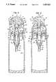
- FIG. 1is an elevation view of an embodiment of a pump actuator of the present invention with its cap in a raised position covering the actuator.
- FIG. 2is an elevation view of the pump actuator of FIG. 1 with its cap in a retracted position exposing the actuator.
- FIG. 3is an exploded perspective view of an embodiment of the pump actuator of the invention.
- FIG. 4is a cross-sectional view of an embodiment of a pump actuator of the present invention with its cap in a raised position covering the actuator.
- FIG. 5is a cross-sectional view of the pump actuator of FIG. 4 with its cap in a retracted position exposing the actuator.
- FIG. 6is a detail cross-sectional view of the pump actuator of FIG. 4 showing the cap in its raised position.
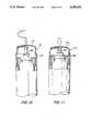
- FIG. 7is a cross-sectional view of another embodiment of an actuator of the present invention with its cap in a raised position covering the actuator.
- FIG. 8is a top plan view of the actuator of FIG. 7.
- FIG. 9is a perspective view of an upper collar segment of the actuator of FIG. 7.
- FIG. 10is a cross-sectional view of the actuator of FIG. 7 with its cap in a retracted position exposing the actuator.
- FIG. 11is a cross-sectional view of the actuator of FIG. 10 with its cap in a retracted position and the actuator depressed.
- FIG. 12is a cross-sectional view of another embodiment of an actuator of the present invention with its cap in a raised position covering the actuator.
- FIG. 13is a top plan view of the actuator of FIG. 12.
- FIG. 14is a cross-sectional view of the cap of the actuator of FIG. 7.
- FIG. 15is a perspective view of an upper collar segment of the actuator of FIG. 7.
- Pump actuator 10has an actuator body 12 and a cap 22 and is mounted on a pump 50.
- Actuator body 12has a channel 14 extending therethrough from a pump end 16 to a nozzle end 18. Pump end 16 is typically located at the lower end of actuator body 12, and the nozzle end 18 is preferably located along one lateral side of actuator body 12.
- Actuator body 12is preferably a substantially planar body, as seen in FIGS. 1 and 3. A planar body is desirable as it gives a substantial actuation surface on its upper surface 15 of its upper end 17. However, a round body may be used instead if desired.
- nozzle end 18is located along the more narrow side of the slab-like, planar actuator body shown.
- a notched cutaway 20is preferably included below nozzle end 18 of the planar actuator body 12 so that the nozzle end 18 is visibly distinct from the planar body 12. This makes the body 12 easier to orient and makes it easier to understand in which direction the nozzle end 18 is pointed.
- Cap 22is provided with aperture 24 sized to snugly receive the actuator body 12.
- a snug fitis desired to permit the edges of the aperture 24 to scrape off any excess liquid from the nozzle end 18.
- a snug fitprovides a desired substantially flush upper surface when the cap is in the raised position.
- aperture 24is a rectangular slot to receive the substantially planar actuator body 12 of the preferred embodiment.
- Cap 22is slidingly retained on the container 32. Cap 22 is movable on container 32 between a raised position as shown in FIGS. 1 and 5 and a retracted position as shown in FIGS. 2 and 4.
- the actuator body 12fits into the aperture 24 in the cap 22 to enclose the nozzle end 18 and to provide a substantially flush upper surface 23.
- the cap 22has an upper segment 28 having a curved upper surface 30 that is congruent with a curved upper surface 15 of the upper end 17 of the planar actuator body 12. This provides the pump actuator 10 with a sleek and tidy appearance when it is stored or not in use.
- cap 22When cap 22 is in the retracted position it is located such that the actuator body 12 extends upwardly through aperture 24 in cap 22. When the cap 22 is in the retracted position, the actuator body 12 is accessible without obstruction of the nozzle end 18. The user may then push on the upper surface 15 of the actuator body 12 to operate pump 50 to dispense a liquid from the container 32 on which actuator 10 is mounted.
- the container 32comprises a larger diameter lower segment 34 and a smaller diameter upper segment 36 which is sized to telescopically fit inside the cap 22 and retain the cap 22 to the container 32.
- the cap 22is provided with a lower cap skirt 38 which is slidable on the container 32.
- the locking meanscomprise a plurality of resilient locking tabs 40 extending radially outwardly from the upper end of container upper segment 36. Locking tabs 40 are preferably cutaway along their sides from the container upper segment to give resilience. Locking tabs 40 are preferably sharp edged to retain the cap 22 by snap fitting into annular channels 42 and 44 around the inner diameter of cap 22. As can be seen in FIGS. 4-6, annular channel 42 is located in the lower portion of cap 22 while annular channel 44 is located in the upper middle portion of cap 22. The interengagement of locking tabs 40 with annular channel 42 locks the cap 22 in its raised position.
- the capmay be manually moved downwardly until the tabs 40 engage the annular channel 44 to lock cap 22 in its retracted position.
- a thin wall area 45is provided in cap 22 between the channels 42 and 44 so that the cap 22 may be more easily moved from the raised position to the retracted position by simple pulling and pushing on the cap.
- the thin wall areapermits the locking tabs 40 to more easily disengage when movement between the raised and retracted positions is desired.
- Thick wall areas 47 and 49are provided above and below the thin wall area 45 that have wall thicknesses that extend inwardly to a greater distance than the thin wall area 45.
- the thick wall areas 47 and 49prevent unintended disengagement of the locking tabs 40 that could cause the cap 22 to be removed from body 32. It is to be appreciated that the locking tabs could be modified within the scope of the invention, and might include an annular radially extending ring, or more rigid tab elements, and that the mating channels could also be modified.
- a lip 46is preferably provided at the lower edge of cap 22 to abut the shoulder 48 of container 32 when the cap 22 is in the retracted position.
- a reciprocating pump 50is preferably connected to the actuator 10, such that the actuator channel 14 is operably connected to the pump 50.
- actuator body 12is mounted to the upper end of a piston 52, either by interengagement of a rib 54 and a groove 56, or by screw mating surfaces, or by gluing or other securing means.
- Pump 50comprises a hollow body 58, a lower valve 60, a piston 52, and an upper valve 62.
- Hollow body 58has an upper opening in its upper end and a lower opening in its lower end.
- Hollow body 58is generally cylindrical in shape and circular in cross-section.
- the upper openingis substantially the same size as the cross-section of the hollow chamber within the body 58 so that the piston 52 can be inserted therethrough.
- the lower openingis preferably provided in a short tubular extension 64 which extends downwardly from the body 58.
- the tubular extensionis provided so that a diptube 66 may be mounted thereon to extend down into the container 32 onto which the pump 50 is to be mounted.
- Lower valve 60is located in and adapted to close the lower opening in the lower end of body 58 when there is an increase in pressure inside hollow body 58. Valve 60 is operable to open the lower opening during a decrease in pressure inside the hollow body 58.
- Piston 52is fitted into the upper end of body 58. Piston 52 is slidable reciprocally with sealing fit in body 58. Piston 52 has an upper opening in its upper end and a lower opening in its lower end. Piston 52 has upper valve 62 located in its upper end. Upper valve 62 is movable to vent the body 58 during an increase in pressure inside the body 58 and to close the body 58 during a decrease in pressure inside the hollow body 58.
- a piston spring 68is installed to bias the piston 52 against a downward stroke and to bias the piston 52 with an upward stroke. A lower end of the spring retains the lower end of a pump core 70 to retain the core 70 in the body 58.
- Pump 50is retained inside container 32 by a collar 72 formed with container 32 for retaining piston 52 in pump body 58.
- Body 58has a collar 74 which is retained against the container collar 72 by a plurality of retaining protruberances 76 formed in the inner walls of container 32.
- body collar 74may be retained by a groove formed in the inner diameter of container 32.
- the cap 22 and container 32are preferably made of plastic or metal, preferably the same material, to provide a uniform decorative appearance, although other materials may be used for a different decorative effect.
- the pump 50 and its componentsare preferably formed of a plastic material such as polypropylene.
- the actuator body 12is preferably also formed of a plastic material such as polypropylene.
- cap 22is shown in the raised position.
- the consumer who desires to dispense a liquid from the container 32may simply grasp the cap 22 and push it downwardly to release the locking tabs 40 from the channel 42 until the lip 46 of cap 22 is stopped by the shoulder 48 of container 32. At this point the locking tabs 40 are seated in the channel 44 and the actuator body 12 is extending upwardly through the cap 22.
- the consumercan then press on the upper surface 15 to activate the pump 50 to draw liquid from the container and dispense it through nozzle end 18.
- shemay lift up on cap 22, causing the locking tabs 40 to release from channel 44 until the locking tabs 40 engage the channel 42 so that cap 22 is again in the raised position as shown in FIGS. 1 and 5.
- the capcomprises an upper cap segment and a lower cap skirt which has a lesser diameter than the upper cap segment.
- the lower cap skirtfits slidably into and is retained in a channel in the upper end of the container.
- the channelis provided between an outer wall and an inner wall of the upper end of the container.
- the outer wall and the inner wallmay be integrally joined together in a molding process, or the outer wall and the inner wall may comprise separate nesting vessels each having a wall and a base portion, and which are secured together in their base portions.
- the means for locking the cap in its raised positionmay comprise a spring resilient locking tab element extending radially outwardly from the lower cap skirt sufficiently to engage the upper lip of the outer wall of the container to lock the cap in a raised position.
- the locking tab elementis sufficiently resilient to be displaceable radially inwardly to disengage the container to release the cap to move the cap to a retracted position.
- Actuator 110has an actuator body 112 and a cap 122 and is mounted on a container 132.
- Actuator body 112may be substantially as described in reference to actuator body 12 of the pump actuator 10.
- Cap 122is movable on container 132 between a raised position as shown in FIG. 7 and a retracted position as shown in FIGS. 10 and 11 by rotation of the cap 122 and pushing the cap downward. This is due to the engagement of tracking pins 124 in tracks 126 in the upper collar segment 128.
- Upper collar segment 128is preferably a separate piece mounted by crimping or snapping onto a container 132 or it can be integrally formed therewith.
- the tracks 126include a vertical track segment 136 and at least one horizontal track segment 130 on the upper end of the vertical track segment 136 and preferably there is a second horizontal track segment 134 on the lower end of the vertical track segment 136.
- the horizontal track segmentspermit locking of the cap 122 in the raised position and in the retracted position.
- the embodiment of the actuator 110is operable to be uncovered by rotating the cap 122 and pushing it downward. The cap is raised by pulling it upwardly and rotating the cap so that the tracking pins lock in the upper horizontal channel.
- Actuator 210has an actuator body 212 and a cap 222.
- Actuator body 212may be substantially as described in reference to actuator body 12 of the pump actuator 10.
- Cap 222is movable on container 232 between a raised position as shown in FIG. 12 and a retracted position by screw rotation of the cap 222 downward. This is due to the engagement of a mating threading in cap 222 and on upper collar segment 228.
- Collar segment 228can be a separate piece mounted on a container 232 or it can be integrally formed therewith.
- the threaded cappermits locking of the cap 222 in the raised position and in a retracted position.
- an actuator body enclosed with a retractable capthat is retained on a container.
- the capmay be otherwise screw threaded to retract by threading rather than by simple vertical sliding.
- the actuatormay have circular or triangular cross-sections instead of the rectangular cross-section of the substantially planar body 12 of the preferred embodiment.
- Other means for locking the cap in its raised or retracted positionsmay be provided.
Landscapes
- Chemical & Material Sciences (AREA)
- Dispersion Chemistry (AREA)
- Engineering & Computer Science (AREA)
- Mechanical Engineering (AREA)
- Closures For Containers (AREA)
Abstract
Description
Claims (18)
Priority Applications (1)
| Application Number | Priority Date | Filing Date | Title |
|---|---|---|---|
| US07/886,765US5255823A (en) | 1992-05-21 | 1992-05-21 | Actuator and cap for a fluid dispenser |
Applications Claiming Priority (1)
| Application Number | Priority Date | Filing Date | Title |
|---|---|---|---|
| US07/886,765US5255823A (en) | 1992-05-21 | 1992-05-21 | Actuator and cap for a fluid dispenser |
Publications (1)
| Publication Number | Publication Date |
|---|---|
| US5255823Atrue US5255823A (en) | 1993-10-26 |
Family
ID=25389719
Family Applications (1)
| Application Number | Title | Priority Date | Filing Date |
|---|---|---|---|
| US07/886,765Expired - Fee RelatedUS5255823A (en) | 1992-05-21 | 1992-05-21 | Actuator and cap for a fluid dispenser |
Country Status (1)
| Country | Link |
|---|---|
| US (1) | US5255823A (en) |
Cited By (32)
| Publication number | Priority date | Publication date | Assignee | Title |
|---|---|---|---|---|
| US5348201A (en)* | 1993-04-20 | 1994-09-20 | Kerr Group, Inc. | Flip top closure |
| US5497915A (en)* | 1991-08-16 | 1996-03-12 | The English Glass Company Limited | Dispenser pumps |
| US5918774A (en)* | 1997-01-17 | 1999-07-06 | The Procter & Gamble Company | Combined lock and anti-clog feature for spray package |
| FR2777868A1 (en)* | 1998-04-28 | 1999-10-29 | Jean Patou Parfumeur | Protection device for container dispensing nozzle |
| US6135329A (en)* | 1999-10-11 | 2000-10-24 | Creative Packaging Corp. | Universal base pull/push-twist closure |
| EP1035037A3 (en)* | 1999-03-10 | 2000-12-20 | Anne Bodenschatz | A cap for an aerosol |
| GB2317653B (en)* | 1996-09-27 | 2000-12-20 | Unilever Plc | Dual compartment package and pumps |
| US6199726B1 (en) | 1999-05-11 | 2001-03-13 | Vermillion Corporation | Chemical irritant dispenser |
| US6257451B1 (en)* | 2000-06-01 | 2001-07-10 | Saint-Gobain Calmar Inc. | Anti-clog pump sprayer |
| WO2001055008A1 (en)* | 2000-01-28 | 2001-08-02 | G Limited | Dispensing of fluid and/or foam |
| US6290103B1 (en)* | 1998-09-15 | 2001-09-18 | Lir-Usa Manufacturing Co., Inc. | Collapsible cap mechanism for shielding pump actuator and liquid material-dispensing container including the same |
| US6405904B1 (en)* | 1999-03-02 | 2002-06-18 | L'oreal, S.A. | Dispensing head including an outlet |
| US6527749B1 (en)* | 1997-12-19 | 2003-03-04 | United States Surgical Corporation | Two component dispenser system |
| US20040011818A1 (en)* | 2002-07-17 | 2004-01-22 | Qualipac | Fluid-dispensing device provided with locking means |
| WO2004012871A1 (en)* | 2002-08-05 | 2004-02-12 | August Schneider | Device for dispensing a cleaning liquid |
| US20040140328A1 (en)* | 2003-01-21 | 2004-07-22 | Precision Valve Corporation | Gapless aerosol valve actuator |
| WO2005080002A1 (en)* | 2004-02-24 | 2005-09-01 | Boehringer Ingelheim International Gmbh | Atomiser comprising coding means |
| US20050230504A1 (en)* | 2004-04-16 | 2005-10-20 | Alain Marroncles | Spray head for a container with a valve |
| US20060175347A1 (en)* | 2005-02-08 | 2006-08-10 | Mcnulty James F Jr | Housing for chemical irritant dispenser |
| EP1749759A1 (en)* | 2005-08-05 | 2007-02-07 | Unilever Plc | Dispenser cap for a spray device |
| US20070075102A1 (en)* | 2004-02-27 | 2007-04-05 | Moore Kenneth S | Dispensing device |
| US20090039109A1 (en)* | 2005-03-23 | 2009-02-12 | Karl Gisbert Welp | Manual Piston Pump Having a Blockable Dispensing Head For Dispensing Fluid Substances |
| US20090183744A1 (en)* | 2008-01-22 | 2009-07-23 | Paul Graham Hayton | Hand-Held dispensing device |
| US20100224345A1 (en)* | 2009-03-09 | 2010-09-09 | Lance Lyda | Method and Apparatus for Heating Products Dispensed from a Container |
| CN102885689A (en)* | 2011-07-20 | 2013-01-23 | 松下电器产业株式会社 | Mist generator and cosmetic device including mist generator |
| US20130037577A1 (en)* | 2001-04-16 | 2013-02-14 | Ben Z. Cohen | Microdispensing pump |
| US20160296958A1 (en)* | 2015-04-07 | 2016-10-13 | Eos Products, Llc | Liquid dispenser with pump |
| WO2017140542A1 (en)* | 2016-02-16 | 2017-08-24 | Aziende Chimiche Riunite Angelini Francesco A.C.R.A.F. S.P.A. | Dispenser with articulated dispensing tube |
| US20170291186A1 (en)* | 2016-04-08 | 2017-10-12 | Wen-Ching Lee | Portable nebulizer with a dust shield |
| US10948327B2 (en) | 2018-04-11 | 2021-03-16 | Berry Global, Inc. | Fitment or adapter for a fluid container |
| DE102021109837A1 (en) | 2021-04-19 | 2022-10-20 | Alexander Wrobel | Portable liquid dispenser |
| FR3129303A1 (en)* | 2021-11-24 | 2023-05-26 | Comptoir Nouveau De La Parfumerie | Mechanism for opening/closing and spraying for a bottle, for example of perfume, and such a bottle |
Citations (17)
| Publication number | Priority date | Publication date | Assignee | Title |
|---|---|---|---|---|
| US1796785A (en)* | 1925-10-19 | 1931-03-17 | Jr Robert Harding | Cap for collapsible tubes |
| US2700484A (en)* | 1951-07-03 | 1955-01-25 | Gen Closure Corp | Closure for receptacles |
| US2980302A (en)* | 1957-12-09 | 1961-04-18 | Alvin G Ash | Metering liquid dispenser |
| US3120909A (en)* | 1961-08-02 | 1964-02-11 | Ira M Miller | Collapsible container and closure member therefor |
| US3249260A (en)* | 1964-12-18 | 1966-05-03 | Aerosol Res Company | Actuating mechanism |
| US3263869A (en)* | 1964-11-03 | 1966-08-02 | Calmar Inc | Liquid dispenser with overcap |
| US3266680A (en)* | 1964-08-14 | 1966-08-16 | Sydelle R Newman | Material dispensing container and cap therefor |
| US3674184A (en)* | 1969-09-10 | 1972-07-04 | Ronald F Ewald | Self-aligning aerosol overcap and button |
| US3782605A (en)* | 1972-12-18 | 1974-01-01 | Scovill Manufacturing Co | Childproof aerosol actuator consisting of two members, operative by relatively rotating the two members |
| US3844448A (en)* | 1972-04-27 | 1974-10-29 | J Sette | Valve actuating safety cap assembly for pressurized dispensers |
| US4018365A (en)* | 1975-02-04 | 1977-04-19 | Aerosol Inventions & Development S.A. Aidsa | Valve actuators for pressurized dispensers |
| US4344744A (en)* | 1979-01-24 | 1982-08-17 | Pfeiffer Zerstaubervertriebsgesellschaft mbH & Co. KG | Spray pump |
| US4383623A (en)* | 1981-03-17 | 1983-05-17 | Ethyl Products Company | Dispensing closure with stationary axial plug |
| US4817831A (en)* | 1988-03-28 | 1989-04-04 | Theisen G Jerry | Dispensing cap with expandable plug |
| US4991747A (en)* | 1988-10-11 | 1991-02-12 | Risdon Corporation | Sealing pump |
| US5004127A (en)* | 1988-05-11 | 1991-04-02 | Simone Morel | Cap with a rotating casing for flasks, tubes and similar containers |
| US5083682A (en)* | 1989-11-27 | 1992-01-28 | American Dispensing Systems Inc. | Pump dispenser having inlet and outlet ports which are held closed during periods of non use |
- 1992
- 1992-05-21USUS07/886,765patent/US5255823A/ennot_activeExpired - Fee Related
Patent Citations (17)
| Publication number | Priority date | Publication date | Assignee | Title |
|---|---|---|---|---|
| US1796785A (en)* | 1925-10-19 | 1931-03-17 | Jr Robert Harding | Cap for collapsible tubes |
| US2700484A (en)* | 1951-07-03 | 1955-01-25 | Gen Closure Corp | Closure for receptacles |
| US2980302A (en)* | 1957-12-09 | 1961-04-18 | Alvin G Ash | Metering liquid dispenser |
| US3120909A (en)* | 1961-08-02 | 1964-02-11 | Ira M Miller | Collapsible container and closure member therefor |
| US3266680A (en)* | 1964-08-14 | 1966-08-16 | Sydelle R Newman | Material dispensing container and cap therefor |
| US3263869A (en)* | 1964-11-03 | 1966-08-02 | Calmar Inc | Liquid dispenser with overcap |
| US3249260A (en)* | 1964-12-18 | 1966-05-03 | Aerosol Res Company | Actuating mechanism |
| US3674184A (en)* | 1969-09-10 | 1972-07-04 | Ronald F Ewald | Self-aligning aerosol overcap and button |
| US3844448A (en)* | 1972-04-27 | 1974-10-29 | J Sette | Valve actuating safety cap assembly for pressurized dispensers |
| US3782605A (en)* | 1972-12-18 | 1974-01-01 | Scovill Manufacturing Co | Childproof aerosol actuator consisting of two members, operative by relatively rotating the two members |
| US4018365A (en)* | 1975-02-04 | 1977-04-19 | Aerosol Inventions & Development S.A. Aidsa | Valve actuators for pressurized dispensers |
| US4344744A (en)* | 1979-01-24 | 1982-08-17 | Pfeiffer Zerstaubervertriebsgesellschaft mbH & Co. KG | Spray pump |
| US4383623A (en)* | 1981-03-17 | 1983-05-17 | Ethyl Products Company | Dispensing closure with stationary axial plug |
| US4817831A (en)* | 1988-03-28 | 1989-04-04 | Theisen G Jerry | Dispensing cap with expandable plug |
| US5004127A (en)* | 1988-05-11 | 1991-04-02 | Simone Morel | Cap with a rotating casing for flasks, tubes and similar containers |
| US4991747A (en)* | 1988-10-11 | 1991-02-12 | Risdon Corporation | Sealing pump |
| US5083682A (en)* | 1989-11-27 | 1992-01-28 | American Dispensing Systems Inc. | Pump dispenser having inlet and outlet ports which are held closed during periods of non use |
Cited By (55)
| Publication number | Priority date | Publication date | Assignee | Title |
|---|---|---|---|---|
| US5497915A (en)* | 1991-08-16 | 1996-03-12 | The English Glass Company Limited | Dispenser pumps |
| US5348201A (en)* | 1993-04-20 | 1994-09-20 | Kerr Group, Inc. | Flip top closure |
| GB2317653B (en)* | 1996-09-27 | 2000-12-20 | Unilever Plc | Dual compartment package and pumps |
| US5918774A (en)* | 1997-01-17 | 1999-07-06 | The Procter & Gamble Company | Combined lock and anti-clog feature for spray package |
| US6527749B1 (en)* | 1997-12-19 | 2003-03-04 | United States Surgical Corporation | Two component dispenser system |
| FR2777868A1 (en)* | 1998-04-28 | 1999-10-29 | Jean Patou Parfumeur | Protection device for container dispensing nozzle |
| US6290103B1 (en)* | 1998-09-15 | 2001-09-18 | Lir-Usa Manufacturing Co., Inc. | Collapsible cap mechanism for shielding pump actuator and liquid material-dispensing container including the same |
| US6405904B1 (en)* | 1999-03-02 | 2002-06-18 | L'oreal, S.A. | Dispensing head including an outlet |
| EP1035037A3 (en)* | 1999-03-10 | 2000-12-20 | Anne Bodenschatz | A cap for an aerosol |
| US6199726B1 (en) | 1999-05-11 | 2001-03-13 | Vermillion Corporation | Chemical irritant dispenser |
| WO2001027021A1 (en)* | 1999-10-11 | 2001-04-19 | Creative Packaging Corp. | Universal base pull/push-twist closure |
| US6135329A (en)* | 1999-10-11 | 2000-10-24 | Creative Packaging Corp. | Universal base pull/push-twist closure |
| WO2001055008A1 (en)* | 2000-01-28 | 2001-08-02 | G Limited | Dispensing of fluid and/or foam |
| US6257451B1 (en)* | 2000-06-01 | 2001-07-10 | Saint-Gobain Calmar Inc. | Anti-clog pump sprayer |
| US20130037577A1 (en)* | 2001-04-16 | 2013-02-14 | Ben Z. Cohen | Microdispensing pump |
| US8752735B2 (en)* | 2001-04-16 | 2014-06-17 | Ben Z. Cohen | Microdispensing pump |
| US6959842B2 (en)* | 2002-07-17 | 2005-11-01 | Qualipac | Fluid-dispensing device provided with locking means |
| US20040011818A1 (en)* | 2002-07-17 | 2004-01-22 | Qualipac | Fluid-dispensing device provided with locking means |
| WO2004012871A1 (en)* | 2002-08-05 | 2004-02-12 | August Schneider | Device for dispensing a cleaning liquid |
| US20040140328A1 (en)* | 2003-01-21 | 2004-07-22 | Precision Valve Corporation | Gapless aerosol valve actuator |
| US7104427B2 (en)* | 2003-01-21 | 2006-09-12 | Precision Valve Corporation | Gapless aerosol valve actuator |
| WO2005080002A1 (en)* | 2004-02-24 | 2005-09-01 | Boehringer Ingelheim International Gmbh | Atomiser comprising coding means |
| US20060027233A1 (en)* | 2004-02-24 | 2006-02-09 | Boehringer Ingelheim International Gmbh | Nebulizer |
| JP4772032B2 (en)* | 2004-02-24 | 2011-09-14 | ベーリンガー インゲルハイム インターナショナル ゲゼルシャフト ミット ベシュレンクテル ハフツング | Nebulizer |
| US7665461B2 (en) | 2004-02-24 | 2010-02-23 | Boehringer Ingelheim International Gmbh | Nebulizer |
| JP2007522900A (en)* | 2004-02-24 | 2007-08-16 | ベーリンガー インゲルハイム インターナショナル ゲゼルシャフト ミット ベシュレンクテル ハフツング | Nebulizer |
| US20070075102A1 (en)* | 2004-02-27 | 2007-04-05 | Moore Kenneth S | Dispensing device |
| US20050230504A1 (en)* | 2004-04-16 | 2005-10-20 | Alain Marroncles | Spray head for a container with a valve |
| US6991138B2 (en)* | 2004-04-16 | 2006-01-31 | Lindal Ventil Gmbh | Spray head for a container with a valve |
| US20060175347A1 (en)* | 2005-02-08 | 2006-08-10 | Mcnulty James F Jr | Housing for chemical irritant dispenser |
| US7644839B2 (en) | 2005-02-08 | 2010-01-12 | Mcnulty Jr James F | Housing for chemical irritant dispenser |
| US20090039109A1 (en)* | 2005-03-23 | 2009-02-12 | Karl Gisbert Welp | Manual Piston Pump Having a Blockable Dispensing Head For Dispensing Fluid Substances |
| US8505778B2 (en)* | 2005-03-23 | 2013-08-13 | Meadwestvaco Corporation | Manual piston pump having a blockable dispensing head for dispensing fluid substances |
| US20100206907A1 (en)* | 2005-08-05 | 2010-08-19 | Peter Angus | Dispenser Cap for a Spray Device |
| WO2007017039A1 (en)* | 2005-08-05 | 2007-02-15 | Unilever Plc | Dispenser cap for a spray device |
| CN101238048B (en)* | 2005-08-05 | 2010-05-26 | 荷兰联合利华有限公司 | Dispenser cap and spray product with same |
| EP1749759A1 (en)* | 2005-08-05 | 2007-02-07 | Unilever Plc | Dispenser cap for a spray device |
| AU2006278914B2 (en)* | 2005-08-05 | 2009-12-24 | Unilever Global Ip Limited | Dispenser cap for a spray device |
| US8550306B2 (en) | 2005-08-05 | 2013-10-08 | Conopco Inc. | Dispenser cap for a spray device |
| US8123082B2 (en) | 2008-01-22 | 2012-02-28 | McNeil-AB | Hand-held dispensing device |
| US20090183744A1 (en)* | 2008-01-22 | 2009-07-23 | Paul Graham Hayton | Hand-Held dispensing device |
| US20100224345A1 (en)* | 2009-03-09 | 2010-09-09 | Lance Lyda | Method and Apparatus for Heating Products Dispensed from a Container |
| US8276788B2 (en) | 2009-03-09 | 2012-10-02 | Lance Lyda | Method and apparatus for heating products dispensed from a container |
| CN102885689A (en)* | 2011-07-20 | 2013-01-23 | 松下电器产业株式会社 | Mist generator and cosmetic device including mist generator |
| US20160296958A1 (en)* | 2015-04-07 | 2016-10-13 | Eos Products, Llc | Liquid dispenser with pump |
| WO2017140542A1 (en)* | 2016-02-16 | 2017-08-24 | Aziende Chimiche Riunite Angelini Francesco A.C.R.A.F. S.P.A. | Dispenser with articulated dispensing tube |
| JP2019511978A (en)* | 2016-02-16 | 2019-05-09 | アジェンデ・キミケ・リウニテ・アンジェリニ・フランチェスコ・ア・チ・エレ・ア・エフェ・ソシエタ・ペル・アチオニAziende Chimiche Riunite Angelini Francesco A.C.R.A.F.Societa Per Azioni | A sprayer with an articulated dispensing tube. |
| EA038678B1 (en)* | 2016-02-16 | 2021-10-04 | Ацьенде Кимике Рьюните Анджелини Франческо А.К.Р.А.Ф. С.П.А. | Dispenser with articulated dispensing tube |
| US20170291186A1 (en)* | 2016-04-08 | 2017-10-12 | Wen-Ching Lee | Portable nebulizer with a dust shield |
| US10730066B2 (en)* | 2016-04-08 | 2020-08-04 | Wen-Ching Lee | Portable nebulizer with a dust shield |
| US10948327B2 (en) | 2018-04-11 | 2021-03-16 | Berry Global, Inc. | Fitment or adapter for a fluid container |
| DE102021109837A1 (en) | 2021-04-19 | 2022-10-20 | Alexander Wrobel | Portable liquid dispenser |
| DE102021109837B4 (en) | 2021-04-19 | 2023-08-10 | Alexander Wrobel | Portable liquid dispenser |
| FR3129303A1 (en)* | 2021-11-24 | 2023-05-26 | Comptoir Nouveau De La Parfumerie | Mechanism for opening/closing and spraying for a bottle, for example of perfume, and such a bottle |
| WO2023094767A1 (en)* | 2021-11-24 | 2023-06-01 | Comptoir Nouveau De La Parfumerie | Opening/closing and vaporizing mechanism for a bottle, for example a perfume bottle, and such a bottle |
Similar Documents
| Publication | Publication Date | Title |
|---|---|---|
| US5255823A (en) | Actuator and cap for a fluid dispenser | |
| US7857174B2 (en) | Fluid dispenser | |
| US5409146A (en) | Dispensing pump with positive shut-off | |
| US4696415A (en) | Apparatus for dispensing products from a self-sealing dispenser | |
| US8608031B2 (en) | Lockable dispensing head | |
| US5085347A (en) | Pressurized dispenser package | |
| US5482188A (en) | Precompression pump | |
| US2884164A (en) | Fluid dispenser | |
| US6382463B2 (en) | Spray dispensing device with nozzle closure | |
| US4485943A (en) | Dispenser for liquids or pasty products | |
| JP2928360B2 (en) | Manual pump | |
| US7686189B2 (en) | Pocket sized fluid dispenser | |
| US6290103B1 (en) | Collapsible cap mechanism for shielding pump actuator and liquid material-dispensing container including the same | |
| US4389003A (en) | Sliding inlet seal for an atomizing pump dispenser | |
| EP0737518A1 (en) | Manually actuated pump | |
| US7044341B2 (en) | Device for packaging and dispensing a product, such as a cosmetic product | |
| US4056216A (en) | Liquid dispensing pump automatically sealable against leakage | |
| US4679712A (en) | Orifice cover slide actuator lock for viscous product dispenser | |
| CA1313647C (en) | Product dispenser with shiftable closure blade | |
| US5524864A (en) | Check valve made of plastic | |
| US5234132A (en) | Actuator for dispensing pump | |
| EP3426411B1 (en) | Dispenser pumps | |
| US3231142A (en) | Valve actuating cap | |
| WO2004045778A1 (en) | Dispensing pump | |
| US6283335B1 (en) | Oil sprayer with hand operated air pump |
Legal Events
| Date | Code | Title | Description |
|---|---|---|---|
| AS | Assignment | Owner name:RISDON CORPORATION, A DELAWARE CORPORATION, CONNEC Free format text:ASSIGNMENT OF ASSIGNORS INTEREST.;ASSIGNORS:MONJE, LANCE A.;MC NAMARA, STEPHEN P.;REEL/FRAME:006177/0646 Effective date:19920521 Owner name:RISDON CORPORATION, A CORPORATION OF DELAWARE, CON Free format text:ASSIGNMENT OF ASSIGNORS INTEREST.;ASSIGNORS:TICHY, EDWARD;BURES, CRAIG R.;REEL/FRAME:006177/0640 Effective date:19920609 Owner name:RISDON CORPORATION, A CORPORATION OF DELAWARE, CON Free format text:ASSIGNMENT OF ASSIGNORS INTEREST.;ASSIGNOR:MARKET, BROOKS;REEL/FRAME:006177/0643 Effective date:19920526 | |
| FPAY | Fee payment | Year of fee payment:4 | |
| AS | Assignment | Owner name:RISDON/AMS (USA), INC., A DE CORP., CONNECTICUT Free format text:CHANGE OF NAME;ASSIGNOR:RISDON CORPORATION;REEL/FRAME:008783/0161 Effective date:19970528 | |
| REMI | Maintenance fee reminder mailed | ||
| LAPS | Lapse for failure to pay maintenance fees | ||
| STCH | Information on status: patent discontinuation | Free format text:PATENT EXPIRED DUE TO NONPAYMENT OF MAINTENANCE FEES UNDER 37 CFR 1.362 | |
| FP | Lapsed due to failure to pay maintenance fee | Effective date:20011026 |