US5254883A - Electrical current source circuitry for a bus - Google Patents
Electrical current source circuitry for a busDownload PDFInfo
- Publication number
- US5254883A US5254883AUS07/872,919US87291992AUS5254883AUS 5254883 AUS5254883 AUS 5254883AUS 87291992 AUS87291992 AUS 87291992AUS 5254883 AUS5254883 AUS 5254883A
- Authority
- US
- United States
- Prior art keywords
- coupled
- transistors
- bus
- voltage
- transistor
- Prior art date
- Legal status (The legal status is an assumption and is not a legal conclusion. Google has not performed a legal analysis and makes no representation as to the accuracy of the status listed.)
- Expired - Lifetime
Links
Images


Classifications
- H—ELECTRICITY
- H04—ELECTRIC COMMUNICATION TECHNIQUE
- H04L—TRANSMISSION OF DIGITAL INFORMATION, e.g. TELEGRAPHIC COMMUNICATION
- H04L25/00—Baseband systems
- H04L25/02—Details ; arrangements for supplying electrical power along data transmission lines
- H04L25/0264—Arrangements for coupling to transmission lines
- H04L25/028—Arrangements specific to the transmitter end
- H04L25/0282—Provision for current-mode coupling
- H—ELECTRICITY
- H03—ELECTRONIC CIRCUITRY
- H03K—PULSE TECHNIQUE
- H03K19/00—Logic circuits, i.e. having at least two inputs acting on one output; Inverting circuits
- H03K19/0175—Coupling arrangements; Interface arrangements
- H03K19/0185—Coupling arrangements; Interface arrangements using field effect transistors only
- H03K19/018585—Coupling arrangements; Interface arrangements using field effect transistors only programmable
- H—ELECTRICITY
- H04—ELECTRIC COMMUNICATION TECHNIQUE
- H04L—TRANSMISSION OF DIGITAL INFORMATION, e.g. TELEGRAPHIC COMMUNICATION
- H04L25/00—Baseband systems
- H04L25/02—Details ; arrangements for supplying electrical power along data transmission lines
- H04L25/0264—Arrangements for coupling to transmission lines
- H04L25/0298—Arrangement for terminating transmission lines
Definitions
- the present inventionpertains to the field of electrical buses. More particularly, the present invention relates to current source driver circuitry for a high speed bus system.
- Computer systems and other electronic systemstypically use buses for interconnecting integrated circuit components so that the integrated circuit components can communicate with one another.
- Prior busestypically connect masters such as microprocessors and controllers and slaves such as memories and bus transceivers.
- One prior bushas rail to rail voltage swings between a high level voltage of 3.5 to 5 volts and a low level voltage of approximately zero volts.
- Another typical disadvantage of large voltage swing busesis a speed limitation caused by the high slew rate of the bus driver.
- Buses with relatively low rail-to-rail voltage swingshave been developed to minimize power dissipation and noise, especially at high bus frequencies. Certain buses with low voltage swings also typically permit higher frequencies.
- Each master and slave coupled to a prior bustypically includes output driver circuitry for driving signals onto the bus.
- Some prior bus systemshave output drivers that use transistor-transistor logic (“TTL”) circuitry.
- Other prior bus systemshave output drivers that include emitter-coupled logical (“ECL”) circuitry.
- ETLemitter-coupled logical
- Other output driversuse CMOS or N-channel metal oxide semiconductor (“NMOS”) circuitry.
- Gunning transistor logic (“GTL”)has also been used in other prior output drivers.
- One object of the present inventionis to provide an improved current mode driver for a bus.
- Another object of the present inventionis to provide a current mode driver that provides a relatively accurate current.
- Another object of the present inventionis to provide a current mode driver that minimizes current variations when there are variations in supply voltage, temperature, and processing.
- Another object of the present inventionis to provide a current mode driver with a performance that is relatively independent of voltage supply variations, temperature variations, and processing variations.
- Another object of the present inventionis to provide a current mode driver having a user-settable current.
- Another object of the present inventionis to provide a current mode driver that minimizes space.
- the circuitryincludes transistor circuitry coupled between the bus and ground for controlling bus current, control circuitry coupled to the transistor circuitry, and a controller coupled to the control circuitry for controlling the transistor circuitry.
- the controllercomprises a variable level circuit comprising setting means for setting a desired current for the bus and transistor reference means coupled to the setting means.
- the variable level circuitprovides a first voltage.
- a voltage reference meansprovides a reference voltage.
- a comparison meansis coupled to the voltage reference means and to the variable level circuit for comparing the first voltage with the reference voltage.
- Logic circuitryis responsive to a trigger signal from the comparison means. An output of the logic circuitry is coupled to the control circuitry in order to turn on the transistor circuitry in a manner dependent upon an output of the logic circuitry.
- FIG. 1is a block diagram of a bus system, including a master, a plurality of slaves, and a bus;
- FIG. 2is a block diagram of a master and a slave coupled to the bus, wherein the master and slave each includes an interface circuit;
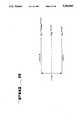
- FIG. 3is a voltage level diagram illustrating the voltage levels of the logic one and logic zero signals of the bus system of FIG. 1;
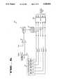
- FIG. 4is a circuit diagram of a current mode driver, including a current controller and an NMOS transistor array;
- FIG. 5is a current-voltage diagram of an NMOS transistor, illustrating the drain current with respect to the drain-to-source voltage and the gate-to-source voltage;
- FIG. 6is a circuit diagram of one embodiment of the current controller of FIG. 4;
- FIG. 7is a circuit diagram of another embodiment of the current controller of FIG. 4;
- FIG. 8is a flow chart that shows the process of calibrating the capacitance of the current controller of FIG. 7;
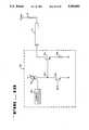
- FIG. 9is a circuit diagram of another current mode driver
- FIG. 10is a circuit diagram of yet another current mode driver.
- FIG. 1is a block diagram of a bus system 10.
- Bus system 10includes a bus 30 that is coupled to master 11 and a plurality of slaves 12a-12n for transferring data between the masters and the slaves.
- Bus 30is a high speed, low voltage swing bus that comprises a total of eleven lines.
- Master 11 and each of the slaves 12a-12nincludes an interface circuit for coupling its respective master or slave to bus 30.
- the interface circuitincludes a plurality of current mode drivers for driving bus 30. For each master and slave, there is one output driver for each transmission line of bus 30. Each of the current mode drivers accurately provides a desired current for the respective line of bus 30.
- each of the current mode driversincludes a plurality of transistors coupled in parallel between a respective line of the bus and ground.
- a logic circuitis coupled to the gates of the plurality of transistors. The widths of the transistors are binary multiples of one another.
- a current controlleris coupled to the logic circuit for controlling the logic circuit in order to turn on or off a particular combination of the plurality of transistors such that the desired current can be selected for the line of the bus.
- the desired current for the line of the busin turn becomes a desired voltage for the line of bus 30.
- the controllerincludes a variable level circuit, a comparator, a counter, and a control logic. Once selected, the desired current is relatively independent of power supply, process, and temperature variations.
- a mastercan communicate with another master (not shown) and with slaves. In contrast, slaves only communicate with masters.
- Master 11 of FIG. 1contains intelligence and generates requests.
- master 11is a microprocessor.
- master 11is a digital signal processor.
- master 11is a graphics processor.
- other types of processors or controllerscan be employed as master 11.
- master 11may be peripheral controller, an input/output ("I/O) controller, a DMA controller, a graphics controller, a DRAM controller, a communications device, or another type of intelligent controller.
- slaves 12a-12ncomprise DRAMs.
- slaves 12a-12nmay include other types of memories, such as electical programmable read only memories (“EPROMs”), flash EPROMs, RAMs, static RAMs (“SRAMs”), and video RAMs (“VRAMs”).
- EPROMselectical programmable read only memories
- SRAMsstatic RAMs
- VRAMsvideo RAMs
- slaves 12a-12nare bus transceivers.
- Master 11 and slaves 12a-12neach includes BusData [8:0]pins, a BusCtrl pin, a BusEnable pin, a ClkToMaster pin, a ClkFromMaster pin, and a V ref pin. These pins receive and transmit low voltage swing signals.
- the BusData pinsare used for data transfer. In one embodiment, the BusData pins comprise nine data pins.
- the BusCtrl and BusEnable pinsare used for transferring bus control signals for controlling communication on bus 30.
- the ClkToMaster and ClkFromMaster pinsreceive clock signals.
- the ClkToMaster pinreceives a "clock-to-master" signal.
- the ClkFromMaster pinreceives a "clock-from-master” signal
- the V ref pinreceives a reference voltage V ref .
- Master 11 and each of the slaves 12a-12nalso includes an SIn pin and an SOut pin.
- the SIn pin and SOut pinsare coupled to form a daisy chain for device initialization.
- Master 11 and each of the slaves 12a-12nalso includes Gnd and GndA ground pins (coupled to lines 18) and Vdd and VddA power supply pins (coupled to lines 19).
- power supply voltages Vdd and VddAare each five volts.
- Bus 30includes BusData data transmission lines 32, a BusCtrl line 14, and a BusEnable line 15.
- Bus 30carries low voltage swing signals that are described in more detail below.
- Data transmission lines 32comprise a data bus for transferring data between master 11 and slaves 12a-12n.
- data transmission lines 32are capable of transferring data at rates up to 500 Megabytes per second.
- Data transmission lines 32comprise nine transmission lines. These transmission lines are matched transmission lines and have controlled impedances. Each line of data transmission lines 32 is terminated at one end by a termination resistor. As shown in FIG. 1, there are nine termination resistors, each connected to a respective one of data transmission lines 32. These termination resistors are collectively referred to as termination resistors 20. Termination resistors 20 are coupled to termination voltage V term .
- each of termination resistors 20is R, which is equal to the line impedance of each transmission line of data transmission lines 32.
- the termination voltage V termis approximately 2.5 volts.
- Each of the termination resistors 20is matched to the respective transmission line impedance. This helps to prevent reflections.
- BusCtrl line 14transfers the bus control signal among master 11 and slaves 12a-12n.
- BusEnable line 15transfers the bus enable signal among master 11 and slaves 12a-12n.
- BusCtrl line 14is terminated at one end by termination resistor 23.
- BusEnable line 15is terminated at one end by termination resistor 21.
- Termination resistors 21 and 23are each coupled to the termination voltage V term .
- Each of the termination resistors 21 and 23is matched to the respective line impedance. This helps to prevent reflections.
- Bus system 10also includes daisy chain line 13 and clock line 16.
- Daisy chain line 13couples the SOut pin of one device to the SIn pin of another device (i.e., chained) for transferring TTL signals for device initialization.
- Line 16is terminated by termination resistor 22.
- Clock line 16is coupled to a clock 35 at one end.
- clock 35is external to and independent of master 11 and slaves 12a-12n.
- the clock signal generated by clock 35travels only in one direction.
- Clock line 16carries the clock signal to master 11 and slaves 12a-12n.
- Clock line 16is folded back to include two segments 16a and 16b. Segment 16a carries a "clock-to-master" signal and segment 16b carries a "clock-from-master" signal.
- Bus system 10also includes a reference voltage line 17 that couples the reference voltage V ref to each of master 11 and slaves 12a-12n.
- the V ref voltageis generated by a voltage divider formed by resistors 25 and 26, with the termination voltage V term being coupled to resistor 25.
- the reference voltage V refis approximately 2.20 volts. In another embodiment, the reference voltage V ref is approximately 2.25 volts.
- Data driven by master 11propagates past slaves 12a-12n along bus 30 and slaves 12a-12n can correctly sense the data provided by master 11. Slaves 12a-12n can also send data to master 11.
- bus system 10may include two masters coupled to the end of bus 30 that is opposite termination resistors 20, 21, and 23.
- Master 11initiates an exchange of data by broadcasting an access request packet.
- Each of slaves 12a-12ndecodes the access request packet and determines whether that slave is the selected slave and the type of access requested. The selected slave then responds appropriately.
- master 11is coupled to the termination voltage V term via a resistor 31.
- Resistor 31is used to set a desired current for bus 30.
- Resistor 31is located external to master 11.
- the resistance of resistor 31is 5R--i.e., five times that of each of termination resistors 20.
- other resistance valuesmay be used for resistor 31 and resistors 20.
- FIG. 2is a block diagram of master 11 and slave 12a.
- slave 12ais a DRAM.
- Master 11includes an engine 70 and peripheral circuitry 71.
- engine 70is a microprocessor.
- Peripheral circuitry 71includes clock circuitry, control circuitry, registers, counters, and status logic.
- Master 11is coupled to bus 30 via an interface circuit 81.
- slave 12aincludes DRAM circuitry 72 and peripheral circuitry 73.
- DRAM circuitry 72includes a memory array and sense circuitry.
- peripheral circuitry 73also includes clock circuitry, control circuitry, registers, counters, and status logic.
- Slave 12ais coupled to bus 30 via interface circuit 82.
- Interface circuits 81 and 82each converts between low-swing voltage levels used by bus 30 and ordinary CMOS logic levels used by much of the circuitry of master 11 and slave 12a.
- Interface circuits 81 and 82each includes a plurality of current mode drivers for driving the data onto bus 30.
- the current mode driversare also referred to as electrical current sources.
- Bus 30is a current mode bus that is driven by the current source output drivers.
- Each of the current mode drivers in interface circuit 81is coupled to a respective transmission line of bus 30. That is also true with respect to each of the current mode drivers in interface circuit 82.
- Slaves 12b-12nhave similar circuitry to that of slave 12a. It is to be appreciated that master 11 and slaves 12a-12n each include current mode output drivers for bus 30.
- bus 30carries low voltage swing signals.
- the current mode drivers of master 11 and slaves 12a-12ncontrol the voltage levels of bus 30.
- the respective bus lineWhen a current mode driver is in an "off" state, the respective bus line either stays at or rises to a high voltage level.
- the current mode driverWhen the current mode driver is in an "off” state, there is approximately zero voltage drop across the respective termination resistor of resistors 20 because the current mode driver is not providing a path to ground for current.
- the high voltage level for bus 30is the termination voltage V term .
- the current mode driverWhen a current mode driver is in an "on" state, the current mode driver provides a path to ground for current for the respective bus line. In other words, when the current mode driver is in an "on” state, pull down current flows through the current driver. The low voltage level of bus 30, is accordingly, determined by the pull down current. The pull down current flows through the respective resistor of termination resistor of resistors 20. A voltage drop appears across the respective termination resistors 20, and a low voltage level appears on the respective line of bus 30. The pull down current (flowing through the output driver and the respective termination resistor) is referred to as the desired current. The magnitude of the desired current can be set or selected by the user to allow for different bus impedance, noise immunity, and power dissipation requirements. Circuitry described below permits the desired current to be substantially independent of processing variations, power supply variations, and temperature variations.
- FIG. 3illustrates preferred voltage levels V OH (i.e., V term ) and V OL for bus system 10.
- V OHthe high voltage level--is approximately 2.5 volts.
- V OLthe low voltage level--is approximately 1.9 volts.
- the reference voltageis 2.2 volts.
- the voltage swingis approximately 0.6 volts.
- the V OH voltagerepresents a logical zero state and the V OL voltage represents a logical one state.
- the V OH voltageis approximately 2.5 volts
- the V OL voltageis approximately 2.0 volts
- the voltage swingis approximately 0.5 volts
- the reference voltageis 2.25 volts.
- the termination voltage V termcan be changed and the low voltage V OL can be selected or set by the user by selecting a desired current.
- V OHis a logical zero state
- V OLis a logical one state
- FIG. 4is a block diagram of a current mode driver 100.
- Driver 100represents one of the plurality of current mode drivers found in master 11 and slaves 12a-12n.
- driver 100is coupled to data transmission line 111 via output pad 110.
- Data transmission line 111is one of the data transmission lines 32 of bus 30.
- Transmission line 111is coupled to the termination voltage V term via termination resistor 112 that resides at one end.
- Termination resistor 112is one of resistors 20.
- Transistor array 101is comprised of five transistors 101a through 101e.
- transistor array 101can include more or fewer than five transistors.
- transistor array 101may include eight transistors.
- transistors 101a-101e of transistor array 101are N-channel MOS transistors.
- Transistors 101a-101e of transistor array 101are coupled in parallel between ground and output pad 110. Each of transistor 101a-101e has a different width. The widths of transistors 101a-101e are governed by a binary relationship. This is shown by the designations 1X, 2X, 4X, 8X, and 16X in FIG. 4. The symbol “x" means "times.” For example, the width of transistor 101b is twice that of transistor 101a. The width of transistor 101c is twice that of transistor 101b.
- Transistors 101a-101eare used to provide a path to ground for current. When one or more of transistors 101a-101e is turned on, current flows through each transistor that is turned on. The current flow results in a voltage drop across resistor 112. This results in the lowering of the voltage on line 111 of bus 30. When transistors 101a-101e are all turned off, then no current flows through transistors 101. This means that no current flows through resistor 112, so there is no voltage drop across resistor 112. Thus, when transistors 101a-101e are all turned off, the termination voltage V term appears on line 111 of bus 30. Thus, transistors 101 are used to control current and voltage with respect to line 111 of bus 30. Turning on various combinations of transistors 101a-101e results in various currents and voltages with respect to line 111 of bus 30.
- the maximum current that transistor array 101 can regulateis I MAX .
- Transistor 101acontributes 1/31 of the I MAX current
- transistor 101bcontributes 2/31 of the I MAX current
- the desired current that driver 100 can providecan be varied in 32 discrete steps from zero to I MAX in order to provide different desired currents relatively accurately. This is done by turning on various combinations of transistors 101a-101e.
- transistors 101a-101ehave width ratios other than binary multiples.
- transistors 101a-101emay be governed by a log width ratio (i.e., 1X, 2X, 5X, 10X, and 20X).
- the widths of transistor 101a-101emay be governed by an integer series (i.e., 1X, 2X, 3X, 4X, and 5X).
- driver 100should provide approximately a 35 milliampere constant current under worst case operating conditions.
- the total width of all the transistors 101a-101e comprising transistor array 101should be approximately 400 micrometers (" ⁇ m"). Therefore, for one embodiment the width of the smallest transistor 101a of transistor array 101 should be approximately 12.9 ⁇ m (i.e., 400 ⁇ m/31).
- FIG. 5illustrates the relationship of the drain current with respect to the drain-source voltage V DS and the gate-source voltage V GS for an NMOS transistor.
- An NMOS transistorwhen operated under the right conditions, acts as a relatively good current source.
- the drain-source voltageis kept above a minimum level (for example, shown by line 94)
- the drain currentis constant and essentially independent of the V DS voltages.
- the bus voltage levelsare chosen to be high enough, a simple NMOS transistor will work well as a current source.
- the larger the voltage levelthe higher the power dissipation when the transistor is in the on state. Therefore, a balance must be established between current mode behavior and power dissipation.
- a range defined by lines 94 and 95 as shown in FIG. 5maintains the V DS above a minimum level (to allow current to be independent of V DS ) while minimizing V DS (to minimize power dissipated during voltage swings).
- driver 100also includes output logic circuitry 102.
- Logic circuitry 102includes five NAND gates 102a-102e and five inverters 106a-106e. The output of each of NAND gates 102a-102e is coupled to the input of a respective one of inverters 106a-106e. The output of each of inverters 106a-106e is coupled to a gate of a respective one of transistors 101a-101e. For example, the output of NAND gate 102a is coupled to inverter 106a and the output of NAND gate 102b is coupled to inverter 106b.
- Each of NAND gates 102a-102eincludes two inputs. One input of each of NAND gates 102a-102e receives an output signal (i.e., drive level) via line 104. The other input of each of NAND gates 102a-102e is coupled to a current controller 120 via one respective line of lines 103a through 103e.
- the drive level signal on line 104comes from other circuitry of the respective master or slave in which output driver 100 resides. For example, if output driver 100 resides in slave 12a, and if slave 12a includes a DRAM, then drive level signal line 104 is coupled to an output signal from the memory array of the DRAM. As another example, if output driver 100 resides in master 11, then drive signal level line 104 is coupled to an output signal from the engine (for example, a microprocessor) of master 11.
- the enginefor example, a microprocessor
- Each NAND gate (of gates 102a-102e) and its respective inverter (of inverters 106a-106e)performs an AND logic function with respect to the inputs to the NAND gate.
- logic circuitry 102instead has five AND gates, each being coupled to a gate of a respective transistor of transistors 101a-101e.
- master 11contains one current controller
- slave 12acontains another current controller
- slave 12bcontains yet another current controller, etc.
- master 11contains eleven sets of output transistors 101 and output logic circuitry 102--one set for each transmission line of bus 30.
- Slave 12acontains eleven other sets of output transistors and output logic circuitry--one set for each transmission line of bus 30.
- the outputs 103a-103e of the particular current controller of that master or slaveare coupled to each of the eleven sets of output logic circuitry for that particular master or slave. For example, if current controller 120 resides in master 11, then the outputs 103a-103e of current controller 120 are coupled not only to output logic circuitry 102, but also to ten other sets of output logic circuitry similar to output logic circuitry 102.
- Master 11would then have a total of eleven sets of output transistors and eleven sets of output logic circuitry. There is one set of output transistors (and output logic circuitry) per transmission line of bus 30.
- the combination of the single current controller 120 and one set of output transistors 101 and output logic circuitry 102can be considered to be one output driver 100.
- the single current controller 120 and the eleven sets of output transistors and output logic circuitrycomprise eleven output drivers. The eleven output drivers have in common (and share) the single current controller 120.
- each current controllerwould be independently coupled to its own particular output logic circuitry associated with a particular transmission line.
- the eleven sets of output transistors (and output logic circuitry)thus would not share a single current controller. Instead, each set of output transistors and output logic circuitry would have its own associated current controller.
- Each of NAND gates 102a-102e and a respective inverter of inverters 106a-106e shown in the embodiment of FIG. 4permits a respective transistor of transistor array 101 to be turned on and off.
- logic circuitry 102provides a control function with respect to the voltage level on line 111 of bus 30. For example, when the output signal coupled to line 104 is a logical low signal, NAND gates 102a-102e and inverters 106a-106e switch each of the transistors 101a-101e off, which in turn cuts off the current flow through transmission line 111. On the other hand, when the output signal coupled to line 104 is a logical high signal, the on and off states of transistors 101a-101e depend upon the signals on respective lines 103a-103e.
- Controller 120uses a reference current to decide what combination of transistors 101a-101e will result in the desired current on transmission line 111 under the existing operating conditions. Controller 120 outputs a five bit binary logic value to logic circuitry 102 on lines 103a-103e. The five bit value is ANDed with the output signal on line 104 to control the turning on of one or more of transistors 101a-101e. For example, when current controller 120 applies a "00100" binary logic value to logic circuitry 102 via lines 103a-103e, NAND gate 102c outputs a logical low signal to inverter 106c when drive level 104 is logically high, which in turn applies a logic high signal to the gate of transistor 101c.
- transistor 101cOn, and transistor 101c thus provides a path to ground for current from line 111. This leads to a voltage drop across resistor 112. The results in a lower voltage on line 111 of bus 30.
- Other transistors 101a-101b and 101d-101eare, however, turned off by the logical zero values sent to logic circuitry 102 via lines 103a-103e.
- current controller 120 of FIG. 4is a resistor reference current controller. In another embodiment, current controller 120 is a capacitor reference current controller.
- the current provided by driver 100is substantially independent of power supply variations, process variations, and temperature variations.
- FIG. 6is a circuit diagram of current controller 320, which is one embodiment of current controller 120 of FIG. 4.
- Current controller 320 of FIG. 6is a resistor reference current controller.
- current controller 320is part of a driver 100 that resides within master 11.
- Current controller 320is especially suited for use in master 11 rather than in slaves 12a-12n because current controller 320 is connected to an external resistor 31.
- master 11is a microprocessor and there is room on a circuit board for an external resistor to be placed next to master.
- slaves 12a-12nreside close together, with less room for any external circuitry.
- current controller 320is part of a driver 100 that resides within one of slaves 12a-12n.
- External resistor 31is used to set the value of the desired current of transmission line 111. External resistor 31 is coupled to the V term termination voltage and a node 130. External resistor 31 is located outside of driver 100 and outside of master 11. For one embodiment, the resistance value of external resistor 31 is 5R. The user can, however, select or choose the particular value of resistor 31 that he or she desires.
- external resistor 31has a variable resistance that is user controllable.
- Current controller 320also includes a transistor array 127.
- Transistor array 127is coupled to node 130.
- Transistor array 127mimics transistor array 101 of FIG. 4.
- Transistor array 127is on the same die as transistor array 101.
- Transistor array 127 and transistor array 101reside within the same master or slave. The difference between transistor arrays 127 and 101 is that the width of each of transistors 127a-127e in transistor array 127 is one tenth of that of the corresponding one of transistors 101a-101e of transistor array 101.
- This 10:1 scalingis done to reduce power consumption inside current controller 320. In addition, this scaling factor also helps to minimize the size of transistor array 127.
- resistor 31 and transistor array 127form a 2:1 scaling factor in comparison with resistor 112 and transistor array 101.
- each of transistors 127a-127ecan be larger or smaller than one tenth of that of the respective one of transistors 101a-101e.
- Current controller 320also includes comparator 129 coupled to node 130. Comparator 129 is also coupled to receive the reference voltage V ref . The output of comparator 129 is coupled to output logic 131 that in turn is coupled to a counter 133. Output logic 131 controls the starting, stopping, and initializing of counter 133. The final count from counter 133 is fed to logic circuitry 102 of driver 100 (of FIG. 4) via a latch 135.
- the output of counter 133is coupled to the gates of transistors 127a-127e via lines 137a through 137e.
- the output of counter 133is also applied to latch 135 via lines 137a-137e.
- Latch 135then supplies the final count of counter 133 to respective NAND gates 102a-102e of logic circuitry 102 (of FIG. 4) via lines 103a-103e.
- the output of counter 133also controls the on and off states of transistors 127a-127e via lines 137a-137e, respectively.
- the output of counter 133is binary form. When counter 133 reaches a final count of "00101" (i.e., five in decimal), for example, transistors 127a and 127c are turned on and transistors 127b and 127d-127e are turned off.
- counter 133When counter 133 is set to initially output all "0" states, transistors 127a-127e of transistor array 127 are thus all initially turned off. Node 130 is pulled up to the V term voltage. Control logic 131 then causes counter 133 to start counting. When counter 133 counts one in binary form, the output of counter 133 turns on transistor 127a. Resistor 31 has a voltage drop across caused by the current flowing through transistor 127a. The voltage at node 130 depends on the current I D flowing through transistor array 127. The voltage at node 130 is then compared with the V ref voltage at comparator 129 to determine if the voltage at node 130 has gone below the V ref voltage. If so, the output of comparator 129 flips and counter 133 stops counting. If not, counter 133 continues its counting.
- counter 133If counter 133 reaches a count of two in binary form, transistor 127b is turned on. The voltage across resistor 31 increases because the current flowing through transistor 127b is doubled which causes the voltage at node 130 to further drop. If counter 133 reaches a count of three, transistors 127a and 127b are both turned on. Counter 133 counts under the control of control logic 131 until the voltage of node 130 reaches the V ref voltage.
- counter 133there are other means besides counter 133 that can determine and control a current.
- logic circuitry performing successive approximationscould be used to determine and set the desired current I.
- counter 133counts at a speed that is equal to the speed of the clock for bus 30. In other words, counter 133 counts at the frequency provided by clock 35 of bus system 10.
- Counter 133stops counting when the voltage at node 130 starts to go below the V ref voltage level.
- the output of comparator 129then flips, which causes control logic 131 to stop counting.
- Particular combination of transistors 127a-127eprovide the current I D that can cause the voltage at node 130 to be slightly less than the V ref voltage.
- the final count of counter 133causes the particular combination of transistors 127a-127e to conduct such that the current I D causes the voltage at node 130 to be approximately equal to V ref .
- the final countis then latched by latch 135 and then coupled to logic circuitry 102 to turn on the same combination of transistors 101a-101e of transistor array 101.
- the desired current Ican thus be accurately set for transmission line 111. Given that the desired current I flows through resistor 112, a desired low voltage V OL can also be accurately set for transmission line 111.
- transistors 127a-127creceive logical high signals via lines 137a-137c while transistors 127d-127e receive logical low signals via lines 137d-137e. Therefore, transistors 127a-127c are turned on and transistors 127d-127e are turned off. At this point the desired control current I D provided by transistors 127a-127c is such that the voltage at node 130 is approximately equal to V ref .
- the count of counter 133represents the value that can turn on the same combination of transistors 101a-101e to provide the desired current I on transmission line 111.
- the desired current Iresults in a V OL voltage on transmission line 111 given the current flow through termination resistor 112.
- counter 133is initialized to all "1" states.
- counter 133When counter 133 is set to initially output all “1" states, transistors 127a-127e of transistor array 127 are all initially turned on. Node 130 is pulled below the V ref voltage.
- Control logic 131then causes counter 133 to start counting down, which turns off some of transistors 127a-127e according to the count of counter 133.
- Counter 133continues to count until the voltage at node 130 reaches the V ref voltage, at which time comparator 129 issues a logical high signal to control logic 131.
- Control logic 131then causes counter 133 to stop counting.
- the count of counter 133is such that transistor array 101 causes a 2(V term -V ref ) voltage drop across resistor 112 to achieve a symmetric swing around V ref .
- control logic 131 and counter 133can be designed such that the output of latch 135 is close to or at the optimum counter value most of the time.
- measurementsare made at regular intervals--for example, one measurement per millisecond. This will usually be sufficient to track temperature changes.
- transistor array 127 of current controller 320 and transistor array 101reside on the same chip, their output currents track each other, which in turn causes the output current of transistor array 101 (i.e., the desired current I) to be substantially independent of processing variations, power supply variations and temperature variations.
- FIG. 7is a circuit diagram of capacitor reference controller 420.
- Capacitance reference controller 420is another embodiment of current controller 120 of FIG. 4.
- capacitor reference controller 420is part of a current driver 100 that resides in one of the slaves 12a-12n.
- Capacitor reference current controller 420is especially suited for each of the slaves 12a-12n because capacitor current controller 420 does not require an external off-chip resistor.
- Capacitor reference current controller 420instead uses on-chip capacitors, which minimizes the use of pins and off chip components. This in turn allows the slaves to be arranged close to each other.
- capacitor reference controller 420is part of driver 100 that resides within master 11.
- a capacitor array 163is provided to allow a user to set the value of the desired current on transmission line 111 of FIG. 4.
- Capacitor reference current controller 420relies on the measurement of the time that it takes to ramp capacitor array 163 from zero volts to V ref voltage. When the current ramping capacitor array 163 is proportional to the desired current on transmission line 111, then the time required to reach V ref will depend upon the desired current, temperature, and voltage.
- controller 420includes a current mirror circuit formed by P-channel transistors 151 and 152 and N-channel transistor 153.
- the current mirror circuittakes the pull down current provided by transistor 153 and produces a pull-up current that is portional to 1/m that of transistor 153.
- Transistor 151has a width that is m times that of transistor 152.
- the current mirror circuitacts as the charging source for capacitor array 163.
- Transistor 153mimics the pull-down capability of the minimum size of transistor 101a.
- Transistor 153has a width that is equal to that of transistor 101a of transistor array 101.
- Transistor 153is fabricated on the same chip (i.e., the same die) as transistor 101a.
- the output of the current mirror circuitis coupled to capacitor array 163 and to one input of comparator 155 via line 167.
- the function of the current mirror circuitis to reduce the current that charges capacitor array 163 so as to reduce the size of capacitors required for capacitor array 163. Therefore, m can be referred to as a scaling factor for reducing the size of capacitors that are required in capacitor array 163.
- Capacitor array 163includes five capacitors 191a through 191e. Each of capacitors 191a-191e is coupled to line 167 via one of transmission gates 192a through 192e. Transmission gates 192a-192e form a register setting circuit 165. Each of transmission gates 192a-192e receives one of REG 1 through REG 5 signals in complementary fashion. For example, transmission gate 192a receives a REG 1 signal and a REG 1 signal. REG 1 signal is an inverted version of the REG 1 signal. The REG signals are provided from a register 422 that receives a register setting value K from master 11 (of FIG. 1).
- Each of transmission gates 192a-192eincludes a P-channel transistor and an N-channel transistor, providing switchable paths to charge and discharge the respective capacitor of capacitors 163.
- the on and off states of each of transmission gates 192a-192edepend on the REG signal applied, which in turn depends on the register setting value K. Therefore, the capacitance connected to line 167 is controllable.
- Controller 120also includes a discharge transistor 171 coupled between line 167 and ground. The on and off states of discharge transistor 171 are controlled by a control logic 157.
- Control logic 157receives the output of comparator 155 and causes counter 159 to begin counting.
- Counter 159outputs a five bit binary logic value to latch 161 via lines 179a-179e.
- Latch 161then applies the latched value to logic circuitry 102 to turn on a particular combination of transistors 101a-101e of FIG. 4 in order to provide the desired current.
- Control logic 157is also coupled to latch 161 via line 177 to control the latching of the output of counter 159.
- control logic 157causes counter 159 to start counting when control logic 157 turns off discharge transistor 171.
- Counter 159stops counting when the output of comparator 155 flips from one state to another. The final count of counter 159 is then loaded into latch 161.
- the capacitance of the smallest capacitor 191a in capacitor array 163can be determined according to the following equation: ##EQU1##
- the letter nrepresents the final count value of counter 159 after counter 159 receives the trigger signal from comparator 155.
- the letter mrepresents the scaling factor with respect to the current mirror (i.e., transistor 151 has a width that is m times that of transistor 152).
- t cyclerepresents the speed at which counter 159 counts which, in one embodiment, is the rate of the clock signal on line 16 (of FIG. 1). In one embodiment, t cycle is 4 nanoseconds per cycle.
- the letter irepresents the current flowing through transistor 153.
- Krepresents the decimal equivalent of the binary register setting. As stated above, K is user controllable. The binary value of K controls transmission gates 192a-192e and determines which ones of capacitors 191a-191e are connected to line 167.
- Current controller 420keeps the left hand side of equation 1 substantially constant. i ⁇ n is the total current in transmission line 111. Because of current controller 420, the desired current I equals i ⁇ n. This means that if the current i flowing through transistor 153 decreases due to variations in temperature, processing, or the power supply, then n increases accordingly.
- the maximum current I MAXis 35 milliamps. Rather, I MAX is not the maximum absolute current. I MAX is the maximum current that is regulated. When K equals 31 (decimal), this means that all transmission gates 192a-192e are turned on, which in turn means that each of the capacitors 191a-191e is connected to line 167. Thus, when K equals 31, the total current i ⁇ n on transmission line 111 equals I MAX , which is 35 milliamps. For a maximum current i ⁇ n of 35 milliamps, a 4 ns cycle time, a V ref of 2.2 volts, a scaling factor m of 20, and a K of 31, the following is true:
- this total capacitance of 3.1 pFis a reasonable total capacitance for on-chip capacitor array 163.
- the right hand side of equation 1is well controlled in manufacture and use, so that the value of K may be calculated in advance by the user.
- each of capacitors 191a-191emight vary during fabrication and might not be identical to the desired value, it is useful to calibrate the register setting K value in order to compensate for variations in capacitance C. This is done through a calibration process described below.
- FIG. 8illustrates the process of calibrating the register setting value K for current controller 420 of FIG. 7
- the calibrationis performed externally from master 11 (of FIG. 1).
- master 11communicates with slaves 12a-12n by sending packets.
- Master 11begins the calibration process at step 200 by setting the initial K value to zero.
- master 11sends the K value in a packet to a slave that needs a calibrated K value.
- the slavesupplies the K value to driver 100 and current controller 420 to set the K value and induce a current and a low voltage V OL on the particular transmission line 111 of bus 30.
- the slavethen sends another packet back to master 11.
- Master 11measures the low voltage V OL of the packet at step 202. Master 11 does so using input samplers.
- master 11compares the sampled V OL with the V ref voltage and determines if V OL is less than or equal to V ref .
- the K valueis increased by one at step 207 and the process returns to step 201, wherein master 11 sends the updated K value to the slave. If V OL is less than or equal to the V ref voltage, then the K value is doubled at step 204. The doubled K value provides a symmetric voltage swing around V ref .
- the calibrated Kis sent from master 11 to the slave and the process ends at step 206.
- Kis incremented in a linear manner as part of the calibration process.
- a binary search with respect to Kis done as part of the calibration process.
- the initial K valuecan be set at step 200 to a value that causes the initial V OL voltage to be below V ref .
- master 11compares the sampled V OL at step 203 with the V ref voltage to determine if V OL is greater than or equal to V ref . If V OL is not greater than or equal to V ref , then the K value is decreased at step 207 and the process repeats from step 201.
- FIG. 9is a circuit diagram of current mode driver 220.
- Current mode driver 220is an alternative embodiment of the present invention.
- Current mode driver 220includes a bipolar transistor 222 coupled to a power supply via resistor 230.
- Transistor 222receives the data that the host master or slave wishes to output to line 111 of bus 30.
- Transistor 222is coupled to a variable current source 226 via a node 232.
- Bipolar transistor 224is coupled between transmission line 111 and node 232.
- Transistor 224is biased by a V BIAS voltage.
- transistors 222 and 224are both bipolar junction transistors.
- Current source 226is also coupled to current controller 228.
- the current of current source 226can be adjusted by current controller 228.
- transistor 224sinks a desired current from line 111. Given the voltage drop across resistor 112, a low voltage signal appears on line 111.
- transistor 222When the data applied to transistor 222 is a logical high signal, transistor 222 is turned on. Resistor 230 is a relatively small resistance. Therefore, when transistor 222 is turned on, the emitter of transistor 224 sees a voltage that is greater than the termination voltage. Therefore, transistor 224 does not conduct current. Therefore, current does not flow through line 111. Accordingly, a high voltage equal to the termination voltage appears on line 111.
- FIG. 10is a circuit diagram of current mode driver 250.
- Current mode driver 250is another alternative embodiment of the present invention.
- Current mode driver 250includes a variable current source 252 coupled to a bipolar junction transistor 258 via a node 262.
- the gate of transistor 258receives data that the host master or slave wishes to output to bus line 111 transmission line 111.
- a bipolar junction transistor 254is coupled between node 262 and a transmission line 111.
- Current source 252is also coupled to a current controller 260.
- Current controller 260can adjust the amount of current flowing through current source 252.
- Current controller 260 and variable current source 252serve functions similar to those provided by current controller 120 and output logic means 102 of FIG. 4.
- transistor 258When the data applied to the gate of transistor 258 is logically high, transistor 258 is turned on. This causes the gate of transistor 254 to be shorted to ground, which turns transistor 254 off. When transistor 254 is off, no current flows through transmission line 111. Therefore, the termination voltage appears on line 111.
- Current controller 260adjusts the current flowing through current source 252 which compensates for Beta variations of transistor 254--i.e., changes in the gain of transistor 254 caused by temperature variations.
- transistor 258when the data applied to the gate of transistor 258 is logically low, transistor 258 is turned off. When this happens, current source 252 causes a portion of the supply voltage to appear on the gate of transistor 254. This turns on transistor 254. When transistor 254 is turned on, current flows through resistor 112, transmission line 111, transistor 254, and resistor 256. A voltage drop appears across resistor 112, and a low voltage appears on transmission line 111.
Landscapes
- Engineering & Computer Science (AREA)
- Computer Hardware Design (AREA)
- Power Engineering (AREA)
- Computer Networks & Wireless Communication (AREA)
- Signal Processing (AREA)
- Physics & Mathematics (AREA)
- Computing Systems (AREA)
- General Engineering & Computer Science (AREA)
- Mathematical Physics (AREA)
- Logic Circuits (AREA)
- Continuous-Control Power Sources That Use Transistors (AREA)
- Dram (AREA)
Abstract
Description
The present invention pertains to the field of electrical buses. More particularly, the present invention relates to current source driver circuitry for a high speed bus system.
Computer systems and other electronic systems typically use buses for interconnecting integrated circuit components so that the integrated circuit components can communicate with one another. Prior buses typically connect masters such as microprocessors and controllers and slaves such as memories and bus transceivers.
Certain prior buses employ relatively large voltage swings. For example, one prior bus has rail to rail voltage swings between a high level voltage of 3.5 to 5 volts and a low level voltage of approximately zero volts.
One disadvantage of large voltage swing buses is the relatively high level of power dissipation. Another disadvantage of large voltage swing buses is the relatively high level of induced noise. The problems of high power dissipation and a high level of induced noise become ever more severe when buses are run at higher and higher frequencies.
Another typical disadvantage of large voltage swing buses is a speed limitation caused by the high slew rate of the bus driver.
Buses with relatively low rail-to-rail voltage swings have been developed to minimize power dissipation and noise, especially at high bus frequencies. Certain buses with low voltage swings also typically permit higher frequencies.
Each master and slave coupled to a prior bus typically includes output driver circuitry for driving signals onto the bus. Some prior bus systems have output drivers that use transistor-transistor logic ("TTL") circuitry. Other prior bus systems have output drivers that include emitter-coupled logical ("ECL") circuitry. Other output drivers use CMOS or N-channel metal oxide semiconductor ("NMOS") circuitry. Gunning transistor logic ("GTL") has also been used in other prior output drivers.
Many prior buses are driven by voltage level signals. It has become advantageous, however, to provide buses that are driven by a current mode output driver. One benefit to a current mode driver is a reduction of peak switching current. For a voltage mode driver the output transistor of the driver must be sized to drive the maximum specified current under worst case operating conditions. Under nominal conditions with less than maximum load, the current transient when the output is switched, but before it reaches the rail, can be very large. The current mode driver, on the other hand, draws a known current regardless of load and operating conditions. In addition, for a voltage mode driver impedance discontinuities occur when the driving device is characterized by a low output impedance when in a sending state. These discontinuities cause reflections which dictate extra bus settling time. Current mode drivers, however, are characterized by a high output impedance so that a signal propagating on the bus encounters no significant discontinuity in line impedance due to a driver in a sending state. Thus, reflections are typically avoided and the required bus settling time is decreased.
An example of a current mode bus is disclosed in U.S. Pat. No. 4,481,625, issued Nov. 6, 1984, entitled High Speed Data Bus System. An NMOS current mode driver for a low voltage swing bus is disclosed in PCT international patent application number PCT/US91/02590 filed Apr. 16, 1991, published Oct. 31, 1991, and entitled Integrated Circuit I/O Using a High Perforamnce Bus Interface.
One disadvantage of certain prior current mode drivers is that current sometimes varies from driver to driver. Variations can also happen over time. Temperature variations, process variations, and power supply variations sometimes cause such variations. Current variations in turn lead to voltage level variations on the bus. Bus voltage level variations can in turn lead to the erroneous reading of bus levels, which can reuslt in the loss of data or other errors. In addition, attempts to design around these variations by raising voltage levels sometimes leads to higher power dissipations, especially in extreme cases. In any event, variations in bus voltage levels are typically more problematic for buses with low voltage swings.
Certain prior feedback techniques have been used to control current. An article by H. Schumacher, J. Dikken, and E. Seevinck entitled CMOS Subnanosecond True-ECL output Buffer, J. Solid State Circuits, Vol. 25, No. 1, pages 150-54 (February 1990) includes a disclosure of the use of feedback.
One object of the present invention is to provide an improved current mode driver for a bus.
Another object of the present invention is to provide a current mode driver that provides a relatively accurate current.
Another object of the present invention is to provide a current mode driver that minimizes current variations when there are variations in supply voltage, temperature, and processing.
Another object of the present invention is to provide a current mode driver with a performance that is relatively independent of voltage supply variations, temperature variations, and processing variations.
Another object of the present invention is to provide a current mode driver having a user-settable current.
Another object of the present invention is to provide a current mode driver that minimizes space.
Electrical current source circuitry for a bus is described. The circuitry includes transistor circuitry coupled between the bus and ground for controlling bus current, control circuitry coupled to the transistor circuitry, and a controller coupled to the control circuitry for controlling the transistor circuitry. The controller comprises a variable level circuit comprising setting means for setting a desired current for the bus and transistor reference means coupled to the setting means. The variable level circuit provides a first voltage. A voltage reference means provides a reference voltage. A comparison means is coupled to the voltage reference means and to the variable level circuit for comparing the first voltage with the reference voltage. Logic circuitry is responsive to a trigger signal from the comparison means. An output of the logic circuitry is coupled to the control circuitry in order to turn on the transistor circuitry in a manner dependent upon an output of the logic circuitry.
Other objects, features, and advantages of the present invention will be apparent from the accompanying drawings and from the detailed description that follows below.
The present invention is illustrated by way of example and not limitation in the figures of the accompanying drawings, in which like references indicate similar elements and in which:
FIG. 1 is a block diagram of a bus system, including a master, a plurality of slaves, and a bus;
FIG. 2 is a block diagram of a master and a slave coupled to the bus, wherein the master and slave each includes an interface circuit;
FIG. 3 is a voltage level diagram illustrating the voltage levels of the logic one and logic zero signals of the bus system of FIG. 1;
FIG. 4 is a circuit diagram of a current mode driver, including a current controller and an NMOS transistor array;
FIG. 5 is a current-voltage diagram of an NMOS transistor, illustrating the drain current with respect to the drain-to-source voltage and the gate-to-source voltage;
FIG. 6 is a circuit diagram of one embodiment of the current controller of FIG. 4;
FIG. 7 is a circuit diagram of another embodiment of the current controller of FIG. 4;
FIG. 8 is a flow chart that shows the process of calibrating the capacitance of the current controller of FIG. 7;
FIG. 9 is a circuit diagram of another current mode driver;
FIG. 10 is a circuit diagram of yet another current mode driver.
FIG. 1 is a block diagram of abus system 10.Bus system 10 includes abus 30 that is coupled to master 11 and a plurality of slaves 12a-12n for transferring data between the masters and the slaves.Bus 30 is a high speed, low voltage swing bus that comprises a total of eleven lines.
Master 11 and each of the slaves 12a-12n includes an interface circuit for coupling its respective master or slave tobus 30. The interface circuit includes a plurality of current mode drivers for drivingbus 30. For each master and slave, there is one output driver for each transmission line ofbus 30. Each of the current mode drivers accurately provides a desired current for the respective line ofbus 30.
As described in more detail below, each of the current mode drivers includes a plurality of transistors coupled in parallel between a respective line of the bus and ground. A logic circuit is coupled to the gates of the plurality of transistors. The widths of the transistors are binary multiples of one another. A current controller is coupled to the logic circuit for controlling the logic circuit in order to turn on or off a particular combination of the plurality of transistors such that the desired current can be selected for the line of the bus. The desired current for the line of the bus in turn becomes a desired voltage for the line ofbus 30. The controller includes a variable level circuit, a comparator, a counter, and a control logic. Once selected, the desired current is relatively independent of power supply, process, and temperature variations.
Withinbus system 10, a master can communicate with another master (not shown) and with slaves. In contrast, slaves only communicate with masters.
Master 11 of FIG. 1 contains intelligence and generates requests. In one embodiment, master 11 is a microprocessor. In another embodiment, master 11 is a digital signal processor. In yet another embodiment, master 11 is a graphics processor. In alternative embodiments, other types of processors or controllers can be employed as master 11. For example, master 11 may be peripheral controller, an input/output ("I/O) controller, a DMA controller, a graphics controller, a DRAM controller, a communications device, or another type of intelligent controller.
Slaves only require a low level of intelligence. In one embodiment, slaves 12a-12n comprise DRAMs. In other embodiments, slaves 12a-12n may include other types of memories, such as electical programmable read only memories ("EPROMs"), flash EPROMs, RAMs, static RAMs ("SRAMs"), and video RAMs ("VRAMs"). For another embodiment, slaves 12a-12n are bus transceivers.
Master 11 and slaves 12a-12n each includes BusData [8:0]pins, a BusCtrl pin, a BusEnable pin, a ClkToMaster pin, a ClkFromMaster pin, and a Vref pin. These pins receive and transmit low voltage swing signals. The BusData pins are used for data transfer. In one embodiment, the BusData pins comprise nine data pins. The BusCtrl and BusEnable pins are used for transferring bus control signals for controlling communication onbus 30. The ClkToMaster and ClkFromMaster pins receive clock signals. The ClkToMaster pin receives a "clock-to-master" signal. The ClkFromMaster pin receives a "clock-from-master" signal The Vref pin receives a reference voltage Vref.
Master 11 and each of the slaves 12a-12n also includes an SIn pin and an SOut pin. The SIn pin and SOut pins are coupled to form a daisy chain for device initialization. Master 11 and each of the slaves 12a-12n also includes Gnd and GndA ground pins (coupled to lines 18) and Vdd and VddA power supply pins (coupled to lines 19). For one embodiment, power supply voltages Vdd and VddA are each five volts.
The resistance value of each oftermination resistors 20 is R, which is equal to the line impedance of each transmission line ofdata transmission lines 32. In one embodiment, the termination voltage Vterm is approximately 2.5 volts. Each of thetermination resistors 20 is matched to the respective transmission line impedance. This helps to prevent reflections.
Data driven by master 11 propagates past slaves 12a-12n alongbus 30 and slaves 12a-12n can correctly sense the data provided by master 11. Slaves 12a-12n can also send data to master 11.
In an alternative embodiment,bus system 10 may include two masters coupled to the end ofbus 30 that isopposite termination resistors
Master 11 initiates an exchange of data by broadcasting an access request packet. Each of slaves 12a-12n decodes the access request packet and determines whether that slave is the selected slave and the type of access requested. The selected slave then responds appropriately.
As described in more detail below, master 11 is coupled to the termination voltage Vterm via aresistor 31.Resistor 31 is used to set a desired current forbus 30.Resistor 31 is located external to master 11. The resistance ofresistor 31 is 5R--i.e., five times that of each oftermination resistors 20. For other embodiments, other resistance values may be used forresistor 31 andresistors 20.
FIG. 2 is a block diagram of master 11 and slave 12a. In FIG. 2, slave 12a is a DRAM.
Master 11 includes anengine 70 andperipheral circuitry 71. For one embodiment of the present invention,engine 70 is a microprocessor.Peripheral circuitry 71 includes clock circuitry, control circuitry, registers, counters, and status logic. Master 11 is coupled tobus 30 via aninterface circuit 81.
Similarly, slave 12a includesDRAM circuitry 72 andperipheral circuitry 73.DRAM circuitry 72 includes a memory array and sense circuitry. Likeperipheral circuitry 71,peripheral circuitry 73 also includes clock circuitry, control circuitry, registers, counters, and status logic. Slave 12a is coupled tobus 30 viainterface circuit 82.
Slaves 12b-12n have similar circuitry to that of slave 12a. It is to be appreciated that master 11 and slaves 12a-12n each include current mode output drivers forbus 30.
Even though the drivers forbus 30 are current mode drivers,bus 30 carries low voltage swing signals. The current mode drivers of master 11 and slaves 12a-12n control the voltage levels ofbus 30. When a current mode driver is in an "off" state, the respective bus line either stays at or rises to a high voltage level. When the current mode driver is in an "off" state, there is approximately zero voltage drop across the respective termination resistor ofresistors 20 because the current mode driver is not providing a path to ground for current. The high voltage level forbus 30 is the termination voltage Vterm.
When a current mode driver is in an "on" state, the current mode driver provides a path to ground for current for the respective bus line. In other words, when the current mode driver is in an "on" state, pull down current flows through the current driver. The low voltage level ofbus 30, is accordingly, determined by the pull down current. The pull down current flows through the respective resistor of termination resistor ofresistors 20. A voltage drop appears across therespective termination resistors 20, and a low voltage level appears on the respective line ofbus 30. The pull down current (flowing through the output driver and the respective termination resistor) is referred to as the desired current. The magnitude of the desired current can be set or selected by the user to allow for different bus impedance, noise immunity, and power dissipation requirements. Circuitry described below permits the desired current to be substantially independent of processing variations, power supply variations, and temperature variations.
FIG. 3 illustrates preferred voltage levels VOH (i.e., Vterm) and VOL forbus system 10. VOH --the high voltage level--is approximately 2.5 volts. VOL --the low voltage level--is approximately 1.9 volts. The reference voltage is 2.2 volts. The voltage swing is approximately 0.6 volts. For one embodiment, the VOH voltage represents a logical zero state and the VOL voltage represents a logical one state.
For an alternative embodiment, the VOH voltage is approximately 2.5 volts, the VOL voltage is approximately 2.0 volts, the voltage swing is approximately 0.5 volts, and the reference voltage is 2.25 volts.
As discussed in more detail below, the termination voltage Vterm can be changed and the low voltage VOL can be selected or set by the user by selecting a desired current.
Given that VOH is a logical zero state, this means that a current mode driver is placed into the "off" (i.e., nonconducting) state when the respective master or slave wants to drive a logical zero signal onto the respective line ofbus 30. Given that VOL is a logical one state, this means that a current mode driver is placed into the "on" (i.e., conducting) state when the respective master or slave wants to drive a logical one signal onto the respective line ofbus 30.
FIG. 4 is a block diagram of acurrent mode driver 100.Driver 100 represents one of the plurality of current mode drivers found in master 11 and slaves 12a-12n.
In FIG. 4,driver 100 is coupled to data transmission line 111 viaoutput pad 110. Data transmission line 111 is one of thedata transmission lines 32 ofbus 30. Transmission line 111 is coupled to the termination voltage Vterm viatermination resistor 112 that resides at one end.Termination resistor 112 is one ofresistors 20.
For one embodiment, transistors 101a-101e oftransistor array 101 are N-channel MOS transistors.
Transistors 101a-101e oftransistor array 101 are coupled in parallel between ground andoutput pad 110. Each of transistor 101a-101e has a different width. The widths of transistors 101a-101e are governed by a binary relationship. This is shown by thedesignations transistor 101c is twice that of transistor 101b.
Transistors 101a-101e are used to provide a path to ground for current. When one or more of transistors 101a-101e is turned on, current flows through each transistor that is turned on. The current flow results in a voltage drop acrossresistor 112. This results in the lowering of the voltage on line 111 ofbus 30. When transistors 101a-101e are all turned off, then no current flows throughtransistors 101. This means that no current flows throughresistor 112, so there is no voltage drop acrossresistor 112. Thus, when transistors 101a-101e are all turned off, the termination voltage Vterm appears on line 111 ofbus 30. Thus,transistors 101 are used to control current and voltage with respect to line 111 ofbus 30. Turning on various combinations of transistors 101a-101e results in various currents and voltages with respect to line 111 ofbus 30.
For one embodiment, the maximum current thattransistor array 101 can regulate is IMAX. Transistor 101a contributes 1/31 of the IMAX current, transistor 101b contributes 2/31 of the IMAX current, etc. Because the current contributed by each of transistors 101a-101e sums atoutput pad 110, the desired current thatdriver 100 can provide can be varied in 32 discrete steps from zero to IMAX in order to provide different desired currents relatively accurately. This is done by turning on various combinations of transistors 101a-101e.
For alternative embodiments, transistors 101a-101e have width ratios other than binary multiples. For example, transistors 101a-101e may be governed by a log width ratio (i.e., 1X, 2X, 5X, 10X, and 20X). As a further example, the widths of transistor 101a-101e may be governed by an integer series (i.e., 1X, 2X, 3X, 4X, and 5X).
For one embodiment,driver 100 should provide approximately a 35 milliampere constant current under worst case operating conditions. In a one micron ("1 μ") MOS technology, the total width of all the transistors 101a-101e comprisingtransistor array 101 should be approximately 400 micrometers ("μm"). Therefore, for one embodiment the width of the smallest transistor 101a oftransistor array 101 should be approximately 12.9 μm (i.e., 400 μm/31).
FIG. 5 illustrates the relationship of the drain current with respect to the drain-source voltage VDS and the gate-source voltage VGS for an NMOS transistor. An NMOS transistor, when operated under the right conditions, acts as a relatively good current source. As long as the drain-source voltage is kept above a minimum level (for example, shown by line 94), the drain current is constant and essentially independent of the VDS voltages. Thus, as long as the bus voltage levels are chosen to be high enough, a simple NMOS transistor will work well as a current source. Nevertheless, the larger the voltage level, the higher the power dissipation when the transistor is in the on state. Therefore, a balance must be established between current mode behavior and power dissipation. For example, a range defined bylines
Referring back to FIG. 4,driver 100 also includesoutput logic circuitry 102.Logic circuitry 102 includes five NAND gates 102a-102e and five inverters 106a-106e. The output of each of NAND gates 102a-102e is coupled to the input of a respective one of inverters 106a-106e. The output of each of inverters 106a-106e is coupled to a gate of a respective one of transistors 101a-101e. For example, the output of NAND gate 102a is coupled to inverter 106a and the output ofNAND gate 102b is coupled toinverter 106b.
Each of NAND gates 102a-102e includes two inputs. One input of each of NAND gates 102a-102e receives an output signal (i.e., drive level) vialine 104. The other input of each of NAND gates 102a-102e is coupled to acurrent controller 120 via one respective line oflines 103a through 103e.
For one embodiment, the drive level signal online 104 comes from other circuitry of the respective master or slave in whichoutput driver 100 resides. For example, ifoutput driver 100 resides in slave 12a, and if slave 12a includes a DRAM, then drivelevel signal line 104 is coupled to an output signal from the memory array of the DRAM. As another example, ifoutput driver 100 resides in master 11, then drivesignal level line 104 is coupled to an output signal from the engine (for example, a microprocessor) of master 11.
Each NAND gate (of gates 102a-102e) and its respective inverter (of inverters 106a-106e) performs an AND logic function with respect to the inputs to the NAND gate.
For one alternative embodiment,logic circuitry 102 instead has five AND gates, each being coupled to a gate of a respective transistor of transistors 101a-101e.
For one preferred embodiment, there is onecurrent controller 120 per master and per slave. For example, master 11 contains one current controller, slave 12a contains another current controller, slave 12b contains yet another current controller, etc.
For that embodiment, however, there are eleven sets of output transistors and output logic circuitry per master and per slave. For example, master 11 contains eleven sets ofoutput transistors 101 andoutput logic circuitry 102--one set for each transmission line ofbus 30. Slave 12a contains eleven other sets of output transistors and output logic circuitry--one set for each transmission line ofbus 30. Within each master or slave, theoutputs 103a-103e of the particular current controller of that master or slave are coupled to each of the eleven sets of output logic circuitry for that particular master or slave. For example, ifcurrent controller 120 resides in master 11, then theoutputs 103a-103e ofcurrent controller 120 are coupled not only tooutput logic circuitry 102, but also to ten other sets of output logic circuitry similar tooutput logic circuitry 102. Master 11 would then have a total of eleven sets of output transistors and eleven sets of output logic circuitry. There is one set of output transistors (and output logic circuitry) per transmission line ofbus 30. The combination of the singlecurrent controller 120 and one set ofoutput transistors 101 andoutput logic circuitry 102 can be considered to be oneoutput driver 100. The singlecurrent controller 120 and the eleven sets of output transistors and output logic circuitry comprise eleven output drivers. The eleven output drivers have in common (and share) the singlecurrent controller 120.
For an alternative embodiment, there are eleven current controllers per master and per slave. For example, master 11 would contain eleven current controllers. For that alternative embodiment, each current controller would be independently coupled to its own particular output logic circuitry associated with a particular transmission line. For that alternative embodiment, the eleven sets of output transistors (and output logic circuitry) thus would not share a single current controller. Instead, each set of output transistors and output logic circuitry would have its own associated current controller.
Each of NAND gates 102a-102e and a respective inverter of inverters 106a-106e shown in the embodiment of FIG. 4 permits a respective transistor oftransistor array 101 to be turned on and off. Thus,logic circuitry 102 provides a control function with respect to the voltage level on line 111 ofbus 30. For example, when the output signal coupled toline 104 is a logical low signal, NAND gates 102a-102e and inverters 106a-106e switch each of the transistors 101a-101e off, which in turn cuts off the current flow through transmission line 111. On the other hand, when the output signal coupled toline 104 is a logical high signal, the on and off states of transistors 101a-101e depend upon the signals onrespective lines 103a-103e.
In one embodiment,current controller 120 of FIG. 4 is a resistor reference current controller. In another embodiment,current controller 120 is a capacitor reference current controller.
The current provided bydriver 100 is substantially independent of power supply variations, process variations, and temperature variations.
FIG. 6 is a circuit diagram ofcurrent controller 320, which is one embodiment ofcurrent controller 120 of FIG. 4.Current controller 320 of FIG. 6 is a resistor reference current controller.
For one embodiment,current controller 320 is part of adriver 100 that resides within master 11.Current controller 320 is especially suited for use in master 11 rather than in slaves 12a-12n becausecurrent controller 320 is connected to anexternal resistor 31. For one embodiment, master 11 is a microprocessor and there is room on a circuit board for an external resistor to be placed next to master. For one embodiment, slaves 12a-12n reside close together, with less room for any external circuitry.
For an alternative embodiment, however,current controller 320 is part of adriver 100 that resides within one of slaves 12a-12n.
For an alternative embodiment,external resistor 31 has a variable resistance that is user controllable.
For alternative embodiments, the width of each of transistors 127a-127e can be larger or smaller than one tenth of that of the respective one of transistors 101a-101e.
The output ofcounter 133 is coupled to the gates of transistors 127a-127e via lines 137a through 137e. The output ofcounter 133 is also applied to latch 135 via lines 137a-137e.Latch 135 then supplies the final count ofcounter 133 to respective NAND gates 102a-102e of logic circuitry 102 (of FIG. 4) vialines 103a-103e. The output ofcounter 133 also controls the on and off states of transistors 127a-127e via lines 137a-137e, respectively. The output ofcounter 133 is binary form. Whencounter 133 reaches a final count of "00101" (i.e., five in decimal), for example, transistors 127a and 127c are turned on andtransistors 127b and 127d-127e are turned off.
Whencounter 133 is set to initially output all "0" states, transistors 127a-127e oftransistor array 127 are thus all initially turned off.Node 130 is pulled up to the Vterm voltage.Control logic 131 then causes counter 133 to start counting. When counter 133 counts one in binary form, the output ofcounter 133 turns on transistor 127a.Resistor 31 has a voltage drop across caused by the current flowing through transistor 127a. The voltage atnode 130 depends on the current ID flowing throughtransistor array 127. The voltage atnode 130 is then compared with the Vref voltage atcomparator 129 to determine if the voltage atnode 130 has gone below the Vref voltage. If so, the output ofcomparator 129 flips and counter 133 stops counting. If not,counter 133 continues its counting. Ifcounter 133 reaches a count of two in binary form,transistor 127b is turned on. The voltage acrossresistor 31 increases because the current flowing throughtransistor 127b is doubled which causes the voltage atnode 130 to further drop. Ifcounter 133 reaches a count of three,transistors 127a and 127b are both turned on. Counter 133 counts under the control ofcontrol logic 131 until the voltage ofnode 130 reaches the Vref voltage.
There are other means besidescounter 133 that can determine and control a current. For example, logic circuitry performing successive approximations could be used to determine and set the desired current I.
For one embodiment, counter 133 counts at a speed that is equal to the speed of the clock forbus 30. In other words, counter 133 counts at the frequency provided byclock 35 ofbus system 10.
For example, when counter 133 stops counting at a count of "00111" (in binary form), transistors 127a-127c receive logical high signals via lines 137a-137c while transistors 127d-127e receive logical low signals vialines 137d-137e. Therefore, transistors 127a-127c are turned on and transistors 127d-127e are turned off. At this point the desired control current ID provided by transistors 127a-127c is such that the voltage atnode 130 is approximately equal to Vref.
Because of the 10:1 scaling of the widths of transistors 101a-101e (of FIG. 4) with respect to transistors 127a-127e and because of the 5:1 scaling ofresistors counter 133 represents the value that can turn on the same combination of transistors 101a-101e to provide the desired current I on transmission line 111. The desired current I results in a VOL voltage on transmission line 111 given the current flow throughtermination resistor 112.
For an alternative embodiment,counter 133 is initialized to all "1" states. Whencounter 133 is set to initially output all "1" states, transistors 127a-127e oftransistor array 127 are all initially turned on.Node 130 is pulled below the Vref voltage.Control logic 131 then causes counter 133 to start counting down, which turns off some of transistors 127a-127e according to the count ofcounter 133.Counter 133 continues to count until the voltage atnode 130 reaches the Vref voltage, at whichtime comparator 129 issues a logical high signal to controllogic 131.Control logic 131 then causes counter 133 to stop counting.
Because of the 2:1 scaling factor of the resistances ofresistor 31 andtransistor array 127 of FIG. 6 with respect to the resistances ofresistor 112 andtransistor array 101 of FIG. 4, the count ofcounter 133 is such thattransistor array 101 causes a 2(Vterm -Vref) voltage drop acrossresistor 112 to achieve a symmetric swing around Vref.
It is to be appreciated thatcontrol logic 131 and counter 133 can be designed such that the output oflatch 135 is close to or at the optimum counter value most of the time. For one embodiment, measurements are made at regular intervals--for example, one measurement per millisecond. This will usually be sufficient to track temperature changes.
Becausetransistor array 127 ofcurrent controller 320 and transistor array 101 (FIG. 4) reside on the same chip, their output currents track each other, which in turn causes the output current of transistor array 101 (i.e., the desired current I) to be substantially independent of processing variations, power supply variations and temperature variations.
FIG. 7 is a circuit diagram ofcapacitor reference controller 420.Capacitance reference controller 420 is another embodiment ofcurrent controller 120 of FIG. 4. For one embodiment,capacitor reference controller 420 is part of acurrent driver 100 that resides in one of the slaves 12a-12n. Capacitor referencecurrent controller 420 is especially suited for each of the slaves 12a-12n because capacitorcurrent controller 420 does not require an external off-chip resistor. Capacitor referencecurrent controller 420 instead uses on-chip capacitors, which minimizes the use of pins and off chip components. This in turn allows the slaves to be arranged close to each other.
For an alternative embodiment, however,capacitor reference controller 420 is part ofdriver 100 that resides within master 11.
In FIG. 7, acapacitor array 163 is provided to allow a user to set the value of the desired current on transmission line 111 of FIG. 4. Capacitor referencecurrent controller 420 relies on the measurement of the time that it takes to rampcapacitor array 163 from zero volts to Vref voltage. When the current rampingcapacitor array 163 is proportional to the desired current on transmission line 111, then the time required to reach Vref will depend upon the desired current, temperature, and voltage.
In FIG. 7,controller 420 includes a current mirror circuit formed by P-channel transistors channel transistor 153. The current mirror circuit takes the pull down current provided bytransistor 153 and produces a pull-up current that is portional to 1/m that oftransistor 153.Transistor 151 has a width that is m times that oftransistor 152. The current mirror circuit acts as the charging source forcapacitor array 163.Transistor 153 mimics the pull-down capability of the minimum size of transistor 101a.Transistor 153 has a width that is equal to that of transistor 101a oftransistor array 101.Transistor 153 is fabricated on the same chip (i.e., the same die) as transistor 101a. The output of the current mirror circuit is coupled tocapacitor array 163 and to one input ofcomparator 155 vialine 167. The function of the current mirror circuit is to reduce the current that chargescapacitor array 163 so as to reduce the size of capacitors required forcapacitor array 163. Therefore, m can be referred to as a scaling factor for reducing the size of capacitors that are required incapacitor array 163.
Each of transmission gates 192a-192e includes a P-channel transistor and an N-channel transistor, providing switchable paths to charge and discharge the respective capacitor ofcapacitors 163. The on and off states of each of transmission gates 192a-192e depend on the REG signal applied, which in turn depends on the register setting value K. Therefore, the capacitance connected toline 167 is controllable.
During operation,control logic 157 causes counter 159 to start counting whencontrol logic 157 turns offdischarge transistor 171.Counter 159 stops counting when the output ofcomparator 155 flips from one state to another. The final count ofcounter 159 is then loaded intolatch 161.
The capacitance of the smallest capacitor 191a incapacitor array 163 can be determined according to the following equation: ##EQU1##
The letter n represents the final count value ofcounter 159 aftercounter 159 receives the trigger signal fromcomparator 155. The letter m represents the scaling factor with respect to the current mirror (i.e.,transistor 151 has a width that is m times that of transistor 152). tcycle represents the speed at which counter 159 counts which, in one embodiment, is the rate of the clock signal on line 16 (of FIG. 1). In one embodiment, tcycle is 4 nanoseconds per cycle. The letter i represents the current flowing throughtransistor 153. K represents the decimal equivalent of the binary register setting. As stated above, K is user controllable. The binary value of K controls transmission gates 192a-192e and determines which ones of capacitors 191a-191e are connected toline 167.
For one embodiment, the maximum current IMAX is 35 milliamps. Rather, IMAX is not the maximum absolute current. IMAX is the maximum current that is regulated. When K equals 31 (decimal), this means that all transmission gates 192a-192e are turned on, which in turn means that each of the capacitors 191a-191e is connected toline 167. Thus, when K equals 31, the total current i·n on transmission line 111 equals IMAX, which is 35 milliamps. For a maximum current i·n of 35 milliamps, a 4 ns cycle time, a Vref of 2.2 volts, a scaling factor m of 20, and a K of 31, the following is true:
C=0.1pF (2)
Given that the capacitances of capacitors 191a-191e are governed by thebinary relationship capacitor array 163 equals: ##EQU2##
Because the value of capacitance C is 0.1 pF, the following is true:
C.sub.TOTAL =31·0.1pF=3.1pF (4)
For one embodiment of the present invention, this total capacitance of 3.1 pF is a reasonable total capacitance for on-chip capacitor array 163.
In some embodiments, the right hand side ofequation 1 is well controlled in manufacture and use, so that the value of K may be calculated in advance by the user.
Because the capacitance of each of capacitors 191a-191e might vary during fabrication and might not be identical to the desired value, it is useful to calibrate the register setting K value in order to compensate for variations in capacitance C. This is done through a calibration process described below.
FIG. 8 illustrates the process of calibrating the register setting value K forcurrent controller 420 of FIG. 7 The calibration is performed externally from master 11 (of FIG. 1).
Referring to FIG. 8, master 11 communicates with slaves 12a-12n by sending packets. Master 11 begins the calibration process atstep 200 by setting the initial K value to zero. Atstep 201, master 11 sends the K value in a packet to a slave that needs a calibrated K value. The slave supplies the K value todriver 100 andcurrent controller 420 to set the K value and induce a current and a low voltage VOL on the particular transmission line 111 ofbus 30. The slave then sends another packet back to master 11. Master 11 measures the low voltage VOL of the packet atstep 202. Master 11 does so using input samplers. Atstep 203, master 11 compares the sampled VOL with the Vref voltage and determines if VOL is less than or equal to Vref. If not, the K value is increased by one atstep 207 and the process returns to step 201, wherein master 11 sends the updated K value to the slave. If VOL is less than or equal to the Vref voltage, then the K value is doubled atstep 204. The doubled K value provides a symmetric voltage swing around Vref. Atstep 205, the calibrated K is sent from master 11 to the slave and the process ends atstep 206.
For one embodiment, K is incremented in a linear manner as part of the calibration process. For an alternative embodiment, a binary search with respect to K is done as part of the calibration process.
For an alternative embodiment, the initial K value can be set atstep 200 to a value that causes the initial VOL voltage to be below Vref. For this alternative embodiment, master 11 compares the sampled VOL atstep 203 with the Vref voltage to determine if VOL is greater than or equal to Vref. If VOL is not greater than or equal to Vref, then the K value is decreased atstep 207 and the process repeats fromstep 201.
FIG. 9 is a circuit diagram ofcurrent mode driver 220.Current mode driver 220 is an alternative embodiment of the present invention.Current mode driver 220 includes abipolar transistor 222 coupled to a power supply viaresistor 230.Transistor 222 receives the data that the host master or slave wishes to output to line 111 ofbus 30.Transistor 222 is coupled to a variablecurrent source 226 via anode 232.
During operation, when the data is a logical low signal that turns offtransistor 222, current can flow throughresistor 112, transmission line 111,transistor 224, andcurrent source 226.Transistor 224 sinks a desired current from line 111. Given the voltage drop acrossresistor 112, a low voltage signal appears on line 111.
When the data applied totransistor 222 is a logical high signal,transistor 222 is turned on.Resistor 230 is a relatively small resistance. Therefore, whentransistor 222 is turned on, the emitter oftransistor 224 sees a voltage that is greater than the termination voltage. Therefore,transistor 224 does not conduct current. Therefore, current does not flow through line 111. Accordingly, a high voltage equal to the termination voltage appears on line 111.
FIG. 10 is a circuit diagram ofcurrent mode driver 250.Current mode driver 250 is another alternative embodiment of the present invention.Current mode driver 250 includes a variablecurrent source 252 coupled to abipolar junction transistor 258 via anode 262. The gate oftransistor 258 receives data that the host master or slave wishes to output to bus line 111 transmission line 111. Abipolar junction transistor 254 is coupled betweennode 262 and a transmission line 111.
During operation, when the data applied to the gate oftransistor 258 is logically high,transistor 258 is turned on. This causes the gate oftransistor 254 to be shorted to ground, which turnstransistor 254 off. Whentransistor 254 is off, no current flows through transmission line 111. Therefore, the termination voltage appears on line 111.
On the other hand, when the data applied to the gate oftransistor 258 is logically low,transistor 258 is turned off. When this happens,current source 252 causes a portion of the supply voltage to appear on the gate oftransistor 254. This turns ontransistor 254. Whentransistor 254 is turned on, current flows throughresistor 112, transmission line 111,transistor 254, andresistor 256. A voltage drop appears acrossresistor 112, and a low voltage appears on transmission line 111.
In the foregoing specification, the invention has been described with reference to specific embodiments thereof. It will, however, be evident that various modifications and changes may be made thereto without departing from the broader spirit and scope of the invention as set forth in the appended claims. The specification and drawings are, accordingly, to be regarded in an illustrative rather than a restrictive sense.
Claims (39)
1. Electrical current source circuitry for a bus, comprising:
(A) transistor means coupled between the bus and ground for controlling bus current;
(B) control circuitry coupled to the transistor means;
(C) a controller coupled to the control circuitry for controlling the transistor means, wherein the controller comprises:
(1) a variable level circuit comprising
(a) setting means for setting a desired current for the bus; and
(b) transistor reference means coupled to the setting means, wherein the variable level circuit provides a first voltage;
(2) voltage reference means for providing a reference voltage;
(3) comparison means coupled to the voltage reference means and the variable level circuit for comparing the first voltage with the reference voltage;
(4) logic means responsive to a trigger signal from the comparison means, wherein an output of the logic means is coupled to the control circuitry in order to turn on the transistor means in a manner dependent upon the output of the logic means.
2. The electrical current source circuitry of claim 1, wherein
(A) the transistor means comprises a plurality of transistors;
(B) the control circuitry comprises logic circuitry coupled to the gates of the plurality of transistors.
3. The electrical current source circuitry of claim 1, wherein the transistor means comprises a transistor.
4. The electrical current source circuitry of claim 2, wherein the logic means comprises a counter for counting until receiving a trigger signal from the comparison means, wherein the output of the counter is coupled to the logic circuitry in order to turn on a particular combination of the plurality of transistors in a manner dependent upon a count of the counter.
5. The electrical current source circuitry of claim 4, wherein the counter is set to a final count upon receiving the trigger signal from the comparison means, wherein the final count is latched, and wherein the output of the counter coupled to the logic circuitry is the latched final count of the counter.
6. The electrical current source circuitry of claim 2, wherein the setting means is an external resistor.
7. The electrical current source circuitry of claim 2, wherein respective widths of the plurality of transistors coupled between the bus and ground are binary multiples of one another.
8. The electrical current source circuitry of claim 1, wherein the transistor reference means comprises a plurality of transistors.
9. The electrical current source circuitry of claim 8, wherein respective widths of the plurality of transistors of the transistor reference means are substantially smaller than the respective widths of the plurality of transistors coupled between the bus and ground.
10. The electrical current source circuitry of claim 1, wherein the setting means comprises a plurality of capacitors.
11. The electrical current source circuitry of claim 10, wherein the transistor reference means is a current mirror circuit.
12. The electrical current source circuitry of claim 10, wherein respective capacitances of the plurality of capacitors are binary multiples of one another.
13. The electrical current source circuitry of claim 10, wherein the plurality of capacitors are coupled to the transistor reference means in a user-settable manner.
14. The electrical current source circuitry of claim 1, wherein the settable desired current is substantially independent of a power supply variation, a process variation, and a temperature variation.
15. An output driver for an electronic device coupled to a bus, wherein the bus is coupled to a voltage supply via a termination resistor, wherein the output driver comprises:
(A) a plurality of transistors coupled between the bus and ground for controlling bus current;
(B) control circuitry coupled to gates of the plurality of transistors;
(C) a controller coupled to the control circuitry for controlling the plurality of transistors, wherein the controller comprises:
(1) resistor means coupled to the voltage supply for setting a desired current;
(2) transistor reference means comprising a plurality of transistors coupled between the resistor means and ground, wherein the plurality of transistors of the transistor reference means are selectively turned on to provide a variable voltage;
(3) comparison means coupled to receive the variable voltage for comparing the variable voltage with a reference voltage;
(4) a counter; and
(5) control logic coupled to (i) the comparison means and (ii) the counter for causing the counter to count until a particular combination of the plurality of transistors of the transistor reference means is turned on by an output of the counter such that the variable voltage is approximately equal to the reference voltage, wherein the output of the counter is also coupled to the control circuitry in order to turn on a particular combination of the plurality of transistors coupled between the bus and ground.
16. The output driver of claim 15, wherein the control circuitry comprises logic circuitry.
17. The output driver for an electronic device of claim 15, wherein the plurality of transistors coupled between the bus and ground comprise five N-channel metal-oxide semiconductor (NMOS) transistors, wherein respective widths of the five NMOS transistor are binary multiples of one another.
18. The output driver of claim 17, wherein the plurality of transistors of the transistor reference means comprise five NMOS transistors, wherein respective widths of the five NMOS transistors of the transistor reference means are substantially smaller than the widths of the respective five NMOS transistors of the plurality of transistors coupled between the bus and ground.
19. The output driver of claim 15, wherein the resistor means comprises a resistor with a resistance five times a resistance of the termination resistor.
20. The output driver of claim 15, wherein the electronic device is a microprocessor.
21. The output driver of claim 15, wherein the electronic device is a dynamic random access memory (DRAM).
22. The output driver of claim 15, wherein the voltage supply is approximately 2.5 volts and the reference voltage is approximately 2.2 volts.
23. The output driver of claim 15, wherein the control circuitry comprises a plurality of logic gates, wherein each logic gate is coupled to a gate of a respective one of the plurality of transistors.
24. The output driver of claim 15, further comprising a latch coupled to the counter for latching the count of the counter and for supplying the count to the control circuitry.
25. The output driver of claim 15, wherein the settable desired current is substantially independent of a power supply variation, a process variation, and temperature variation.
26. An output driver for an electronic device coupled to a bus, wherein the bus is coupled to a voltage supply via a termination resistor, wherein the output driver comprises:
(A) a plurality of transistors coupled between the bus and ground for controlling bus current;
(B) control circuitry coupled to gates of the plurality of transistors;
(C) a controller coupled to the control circuitry for controlling the plurality of transistors, wherein the controller comprises:
(1) current mirror means coupled to a voltage supply and ground, wherein the current mirror means has an output supplying a current with a predetermined value proportional to a desired current;
(2) capacitor means having a plurality of capacitors selectively coupled to the output of the current mirror means, wherein the capacitor means receives the current from the current mirror means, wherein the capacitor means provides a variable voltage when charged by the current;
(3) comparison means coupled to receive the variable voltage for comparing the variable voltage with a reference voltage;
(4) a counter; and
(5) control logic coupled to (i) the counter, (ii) the comparison means, and (iii) the output of the current mirror means for causing the capacitor means to be charged to the variable voltage and for causing the counter to start counting when the capacitor means is charged, wherein the control logic causes the counter to count until receiving a trigger signal from the comparison means that indicates that the variable voltage is approximately equal to the reference voltage, wherein an output of the counter is coupled to the control circuitry in order to turn on a particular combination of the plurality of transistors in a manner dependent upon a count of the counter.
27. The output driver of claim 26, wherein the control circuitry comprises logic circuitry.
28. The output driver of claim 26, wherein the electronic device is a DRAM.
29. The output driver of claim 26, wherein the electronic device is a microprocessor.
30. The output driver of claim 26, wherein the plurality of transistors comprise five NMOS transistors, wherein respective widths of the five NMOS transistors are binary multiples of one another.
31. The output driver of claim 26, wherein the current mirror means comprises a first P-channel transistor, a second P-channel transistor, and a first N-channel transistor, wherein a width of the first N-channel transistor is equal to that of one of the plurality of transistors, wherein a width of the first P-channel transistor is approximately twenty times of that of the second P-channel transistor.
32. The output driver of claim 26, wherein the plurality of the capacitors have capacitances that are binary multiples of one another.
33. The output driver of claim 26, wherein the plurality of capacitors are coupled to the output of the current mirror means in a user-settable manner.
34. The output driver of claim 26, wherein the reference voltage is approximately 2.2 volts and the voltage supply is equal to approximately 2.5 volts.
35. The output driver of claim 27, wherein the logic circuitry comprises a plurality of logic gates, wherein each logic gate coupled to a gate of a respective one of the plurality of transistors.
36. The output driver of claim 26, wherein the settable desired current is substantially independent of a power supply variation, a process variation, and a temperature variation.
37. The output driver of claim 26, further comprising a latch coupled to the counter for latching the count of the counter and for supplying the count to the control circuitry.
38. The output driver of claim 26, wherein the electronic device is a slave, wherein a master is coupled to the bus, and wherein the master causes selective ones of the plurality of capacitors to be coupled to the output of the current mirror means.
39. In a bus system comprising a bus, a master, and a slave with an output driver, a method for setting a current of the output driver for the bus of the slave comprising the steps of:
(A) setting a register setting to a first value;
(B) having the master send the register setting to the output driver of the slave;
(C) having the slave couple selective ones of a plurality of capacitors to an output of a current mirror means of the output driver based upon the register setting received from the master;
(D) causing the plurality of capacitors that are coupled to the output of the current means to charge to a variable voltage while a counter counts;
(E) comparing the variable voltage to a reference voltage;
(F) when the variable voltage approximately equals the variable voltage, then stopping the counter from counting and latching a final count of the counter;
(G) turning on a particular combination of a plurality of transistors coupled between the bus and ground based upon the final count of the counter in order to generate a first voltage level on the bus;
(H) sensing within the master the first voltage on the bus;
(I) comparing within the master the first voltage with the reference voltage;
(J) if the register setting does not approximately equal the reference voltage, then changing the register setting and repeating steps B through J;
(K) if the register setting does approximately equal the reference voltage, then:
(1) setting the register setting to a value that is double a present value of the register setting;
(2) having the master send the register setting to the output driver of the slave;
(3) having the slave couple selective ones of the plurality of capacitors to the output of the current mirror means of the output driver based upon the register setting received from the master.
Priority Applications (5)
| Application Number | Priority Date | Filing Date | Title |
|---|---|---|---|
| US07/872,919US5254883A (en) | 1992-04-22 | 1992-04-22 | Electrical current source circuitry for a bus |
| JP51837993AJP3509097B2 (en) | 1992-04-22 | 1993-03-30 | Bus current source circuit |
| KR1019940701618AKR0179666B1 (en) | 1992-04-22 | 1993-03-30 | Electric current source circuit for bus |
| PCT/US1993/003005WO1993021572A1 (en) | 1992-04-22 | 1993-03-30 | Electrical current source circuitry for a bus |
| AU39716/93AAU3971693A (en) | 1992-04-22 | 1993-03-30 | Electrical current source circuitry for a bus |
Applications Claiming Priority (1)
| Application Number | Priority Date | Filing Date | Title |
|---|---|---|---|
| US07/872,919US5254883A (en) | 1992-04-22 | 1992-04-22 | Electrical current source circuitry for a bus |
Publications (1)
| Publication Number | Publication Date |
|---|---|
| US5254883Atrue US5254883A (en) | 1993-10-19 |
Family
ID=25360599
Family Applications (1)
| Application Number | Title | Priority Date | Filing Date |
|---|---|---|---|
| US07/872,919Expired - LifetimeUS5254883A (en) | 1992-04-22 | 1992-04-22 | Electrical current source circuitry for a bus |
Country Status (5)
| Country | Link |
|---|---|
| US (1) | US5254883A (en) |
| JP (1) | JP3509097B2 (en) |
| KR (1) | KR0179666B1 (en) |
| AU (1) | AU3971693A (en) |
| WO (1) | WO1993021572A1 (en) |
Cited By (220)
| Publication number | Priority date | Publication date | Assignee | Title |
|---|---|---|---|---|
| US5296756A (en)* | 1993-02-08 | 1994-03-22 | Patel Hitesh N | Self adjusting CMOS transmission line driver |
| US5396130A (en)* | 1993-06-29 | 1995-03-07 | International Business Machines Corporation | Method and apparatus for adaptive chip trim adjustment |
| US5428311A (en)* | 1993-06-30 | 1995-06-27 | Sgs-Thomson Microelectronics, Inc. | Fuse circuitry to control the propagation delay of an IC |
| US5438282A (en)* | 1993-06-08 | 1995-08-01 | National Semiconductor Corporation | CMOS BTL compatible bus and transmission line driver |
| WO1995026076A1 (en)* | 1994-03-23 | 1995-09-28 | Telefonaktiebolaget Lm Ericsson | Connecting arrangement |
| US5463331A (en)* | 1993-06-08 | 1995-10-31 | National Semiconductor Corporation | Programmable slew rate CMOS buffer and transmission line driver with temperature compensation |
| US5473575A (en)* | 1990-04-18 | 1995-12-05 | Rambus, Inc. | Integrated circuit I/O using a high performance bus interface |
| US5475336A (en)* | 1994-12-19 | 1995-12-12 | Institute Of Microelectronics, National University Of Singapore | Programmable current source correction circuit |
| US5479115A (en)* | 1994-04-22 | 1995-12-26 | Mitsubishi Denki Kabushiki Kaisha | Signal processing device and level converter circuit |
| US5483184A (en)* | 1993-06-08 | 1996-01-09 | National Semiconductor Corporation | Programmable CMOS bus and transmission line receiver |
| US5498990A (en)* | 1991-11-05 | 1996-03-12 | Monolithic System Technology, Inc. | Reduced CMOS-swing clamping circuit for bus lines |
| US5506541A (en)* | 1993-05-13 | 1996-04-09 | Microunity Systems Engineering, Inc. | Bias voltage distribution system |
| US5532616A (en)* | 1994-08-01 | 1996-07-02 | Texas Instruments Incorporated | On-chip series terminated CMOS(Bi-CMOS) driver |
| US5539341A (en)* | 1993-06-08 | 1996-07-23 | National Semiconductor Corporation | CMOS bus and transmission line driver having programmable edge rate control |
| US5543746A (en)* | 1993-06-08 | 1996-08-06 | National Semiconductor Corp. | Programmable CMOS current source having positive temperature coefficient |
| US5557223A (en)* | 1993-06-08 | 1996-09-17 | National Semiconductor Corporation | CMOS bus and transmission line driver having compensated edge rate control |
| US5559448A (en)* | 1994-04-07 | 1996-09-24 | Siemens Aktiengesellschaft | CMOS terminating resistor circuit |
| US5585741A (en)* | 1994-04-22 | 1996-12-17 | Unitrode Corporation | Impedance emulator |
| US5592123A (en)* | 1995-03-07 | 1997-01-07 | Linfinity Microelectronics, Inc. | Frequency stability bootstrapped current mirror |
| US5592142A (en)* | 1995-09-15 | 1997-01-07 | International Business Machines Corporation | High speed greater than or equal to compare circuit |
| US5592632A (en)* | 1991-11-05 | 1997-01-07 | Monolithic System Technology, Inc. | Defect tolerant integrated circuit subsystem for communication between a module and a bus controller in a wafer-scale integrated circuit system |
| US5608312A (en)* | 1995-04-17 | 1997-03-04 | Linfinity Microelectronics, Inc. | Source and sink voltage regulator for terminators |
| EP0763891A1 (en)* | 1995-09-07 | 1997-03-19 | Telefonaktiebolaget Lm Ericsson | Connecting arrangement |
| US5621335A (en)* | 1995-04-03 | 1997-04-15 | Texas Instruments Incorporated | Digitally controlled output buffer to incrementally match line impedance and maintain slew rate independent of capacitive output loading |
| WO1997018631A1 (en)* | 1995-11-13 | 1997-05-22 | Elonex Technologies, Inc. | Inherently balanced voltage regulation and current supply for bus termination |
| US5635852A (en)* | 1995-04-17 | 1997-06-03 | Linfinity Microelectronics, Inc. | Controllable actice terminator for a computer bus |
| US5655113A (en)* | 1994-07-05 | 1997-08-05 | Monolithic System Technology, Inc. | Resynchronization circuit for a memory system and method of operating same |
| US5663674A (en)* | 1994-05-11 | 1997-09-02 | Siemens Aktiengesellschaft | Circut configuration for generating a reference current |
| US5694060A (en)* | 1993-07-30 | 1997-12-02 | Apple Computer, Inc. | CMOS differential twisted-pair driver |
| WO1997045793A1 (en)* | 1996-05-31 | 1997-12-04 | Rambus, Inc. | Method for setting a current source in a bus output driver |
| US5731731A (en)* | 1995-05-30 | 1998-03-24 | Linear Technology Corporation | High efficiency switching regulator with adaptive drive output circuit |
| US5779753A (en)* | 1996-03-09 | 1998-07-14 | Arzneimittel Gmbh Apotheker Vetter & Co. Ravensburg | Method of and apparatus for treating a solid workpiece, especially a glass tube |
| EP0818092A4 (en)* | 1995-03-27 | 1998-07-22 | Gen Datacomm Ind Inc | High speed synchronous digital data bus system having unterminated data and clock buses |
| US5805873A (en)* | 1994-11-30 | 1998-09-08 | Hitachi Micro Systems, Inc. | Phase linking of output clock with master clock in memory architecture |
| US5818260A (en)* | 1996-04-24 | 1998-10-06 | National Semiconductor Corporation | Transmission line driver having controllable rise and fall times with variable output low and minimal on/off delay |
| US5831467A (en) | 1991-11-05 | 1998-11-03 | Monolithic System Technology, Inc. | Termination circuit with power-down mode for use in circuit module architecture |
| US5838177A (en)* | 1997-01-06 | 1998-11-17 | Micron Technology, Inc. | Adjustable output driver circuit having parallel pull-up and pull-down elements |
| US5843799A (en) | 1991-11-05 | 1998-12-01 | Monolithic System Technology, Inc. | Circuit module redundancy architecture process |
| US5844913A (en)* | 1997-04-04 | 1998-12-01 | Hewlett-Packard Company | Current mode interface circuitry for an IC test device |
| US5870347A (en)* | 1997-03-11 | 1999-02-09 | Micron Technology, Inc. | Multi-bank memory input/output line selection |
| US5872736A (en)* | 1996-10-28 | 1999-02-16 | Micron Technology, Inc. | High speed input buffer |
| WO1999010982A1 (en)* | 1997-08-29 | 1999-03-04 | Rambus Incorporated | Current control technique |
| US5898638A (en)* | 1997-03-11 | 1999-04-27 | Micron Technology, Inc. | Latching wordline driver for multi-bank memory |
| US5917758A (en)* | 1996-11-04 | 1999-06-29 | Micron Technology, Inc. | Adjustable output driver circuit |
| US5920518A (en)* | 1997-02-11 | 1999-07-06 | Micron Technology, Inc. | Synchronous clock generator including delay-locked loop |
| US5923594A (en)* | 1998-02-17 | 1999-07-13 | Micron Technology, Inc. | Method and apparatus for coupling data from a memory device using a single ended read data path |
| US5926032A (en)* | 1995-08-14 | 1999-07-20 | Compaq Computer Corporation | Accommodating components |
| US5926043A (en)* | 1996-07-27 | 1999-07-20 | Lg Semicon Co., Ltd. | Output circuit for a semiconductor device |
| US5926047A (en)* | 1997-08-29 | 1999-07-20 | Micron Technology, Inc. | Synchronous clock generator including a delay-locked loop signal loss detector |
| WO1999038258A1 (en)* | 1998-01-22 | 1999-07-29 | Intel Corporation | Slew rate control circuit |
| US5940608A (en)* | 1997-02-11 | 1999-08-17 | Micron Technology, Inc. | Method and apparatus for generating an internal clock signal that is synchronized to an external clock signal |
| US5946244A (en)* | 1997-03-05 | 1999-08-31 | Micron Technology, Inc. | Delay-locked loop with binary-coupled capacitor |
| US5949254A (en)* | 1996-11-26 | 1999-09-07 | Micron Technology, Inc. | Adjustable output driver circuit |
| US5953284A (en)* | 1997-07-09 | 1999-09-14 | Micron Technology, Inc. | Method and apparatus for adaptively adjusting the timing of a clock signal used to latch digital signals, and memory device using same |
| US5956502A (en)* | 1997-03-05 | 1999-09-21 | Micron Technology, Inc. | Method and circuit for producing high-speed counts |
| US5994922A (en)* | 1996-02-08 | 1999-11-30 | Kabushiki Kaisha Toshiba | Output buffer, semiconductor integrated circuit having output buffer and driving ability adjusting method for output buffer |
| US6008683A (en)* | 1997-10-31 | 1999-12-28 | Credence Systems Corporation | Switchable load for testing a semiconductor integrated circuit device |
| US6011732A (en)* | 1997-08-20 | 2000-01-04 | Micron Technology, Inc. | Synchronous clock generator including a compound delay-locked loop |
| US6014759A (en)* | 1997-06-13 | 2000-01-11 | Micron Technology, Inc. | Method and apparatus for transferring test data from a memory array |
| US6016282A (en)* | 1998-05-28 | 2000-01-18 | Micron Technology, Inc. | Clock vernier adjustment |
| US6016074A (en)* | 1996-09-30 | 2000-01-18 | Nec Corporation | Programmable reference voltage circuit |
| US6029250A (en)* | 1998-09-09 | 2000-02-22 | Micron Technology, Inc. | Method and apparatus for adaptively adjusting the timing offset between a clock signal and digital signals transmitted coincident with that clock signal, and memory device and system using same |
| US6028438A (en)* | 1997-10-31 | 2000-02-22 | Credence Systems Corporation | Current sense circuit |
| US6035407A (en)* | 1995-08-14 | 2000-03-07 | Compaq Computer Corporation | Accomodating components |
| US6044429A (en)* | 1997-07-10 | 2000-03-28 | Micron Technology, Inc. | Method and apparatus for collision-free data transfers in a memory device with selectable data or address paths |
| US6047346A (en)* | 1998-02-02 | 2000-04-04 | Rambus Inc. | System for adjusting slew rate on an output of a drive circuit by enabling a plurality of pre-drivers and a plurality of output drivers |
| US6064224A (en)* | 1998-07-31 | 2000-05-16 | Hewlett--Packard Company | Calibration sharing for CMOS output driver |
| US6072747A (en)* | 1997-11-07 | 2000-06-06 | Samsung Electronics Co., Ltd. | High-speed current setting systems and methods for integrated circuit output drivers |
| US6084426A (en)* | 1997-12-24 | 2000-07-04 | Intel Corporation | Compensated input receiver with controlled switch-point |
| US6087853A (en)* | 1998-06-22 | 2000-07-11 | Lucent Technologies, Inc. | Controlled output impedance buffer using CMOS technology |
| US6087847A (en)* | 1997-07-29 | 2000-07-11 | Intel Corporation | Impedance control circuit |
| US6094075A (en)* | 1997-08-29 | 2000-07-25 | Rambus Incorporated | Current control technique |
| US6094069A (en)* | 1998-02-16 | 2000-07-25 | Mitsubishi Denki Kabushiki Kaisha | Semiconductor integrated circuit having controlled output resistance of an output buffer circuit |
| US6101197A (en)* | 1997-09-18 | 2000-08-08 | Micron Technology, Inc. | Method and apparatus for adjusting the timing of signals over fine and coarse ranges |
| US6108252A (en)* | 1998-02-06 | 2000-08-22 | Samsung Electronics Co., Ltd. | Integrated circuit memory devices having self-test circuits therein and method of testing same |
| US6114885A (en)* | 1997-08-22 | 2000-09-05 | Samsung Electronics Co., Ltd. | Integrated driver circuits having independently programmable pull-up and pull-down circuits therein which match load impedance |
| US6115318A (en)* | 1996-12-03 | 2000-09-05 | Micron Technology, Inc. | Clock vernier adjustment |
| US6151648A (en)* | 1998-03-16 | 2000-11-21 | Jazio, Inc. | High speed bus system and method for using voltage and timing oscillating references for signal detection |
| US6151264A (en)* | 1998-11-09 | 2000-11-21 | Samsung Electronics Co., Ltd. | Integrated circuit memory devices including a single data shift block between first and second memory banks |
| US6157206A (en)* | 1998-12-31 | 2000-12-05 | Intel Corporation | On-chip termination |
| US6157688A (en)* | 1996-10-09 | 2000-12-05 | Fujitsu Limited | Signal transmission system for transmitting signals between LSI chips, receiver circuit for use in the signal transmission system, and semiconductor memory device applying the signal transmission system |
| US6163178A (en)* | 1998-12-28 | 2000-12-19 | Rambus Incorporated | Impedance controlled output driver |
| US6166562A (en)* | 1997-02-26 | 2000-12-26 | Kabushiki Kaisha Toshiba | Semiconductor integrated circuit device |
| US6173432B1 (en) | 1997-06-20 | 2001-01-09 | Micron Technology, Inc. | Method and apparatus for generating a sequence of clock signals |
| US6191645B1 (en)* | 1998-04-16 | 2001-02-20 | Robert Bosch Gmbh | Electronic circuit with partitioned power transistor |
| US6239652B1 (en)* | 1998-06-29 | 2001-05-29 | Hyundai Electronics Co., Ltd. | Internal voltage fall-down circuit |
| US6269451B1 (en) | 1998-02-27 | 2001-07-31 | Micron Technology, Inc. | Method and apparatus for adjusting data timing by delaying clock signal |
| US6275067B1 (en) | 1998-02-25 | 2001-08-14 | Vanguard International Semiconductor Corporation | Multiple-bit, current mode data bus |
| US6275090B1 (en)* | 1995-12-15 | 2001-08-14 | Agere Systems Guardian Corp. | Adaptive resistor trimming circuit |
| US6279090B1 (en) | 1998-09-03 | 2001-08-21 | Micron Technology, Inc. | Method and apparatus for resynchronizing a plurality of clock signals used in latching respective digital signals applied to a packetized memory device |
| US6313670B1 (en) | 1998-11-04 | 2001-11-06 | Samsung Electronics Co., Ltd. | Integrated driver circuits having current control capability |
| US6313694B1 (en)* | 1998-09-24 | 2001-11-06 | Samsung Electronics Co., Ltd. | Internal power voltage generating circuit having a single drive transistor for stand-by and active modes |
| US6323687B1 (en)* | 2000-11-03 | 2001-11-27 | Fujitsu Limited | Output drivers for integrated-circuit chips with VCCQ supply compensation |
| US6327205B1 (en) | 1998-03-16 | 2001-12-04 | Jazio, Inc. | Signal latching of high bandwidth DRAM arrays when skew between different components is higher than signal rate |
| US6338127B1 (en) | 1998-08-28 | 2002-01-08 | Micron Technology, Inc. | Method and apparatus for resynchronizing a plurality of clock signals used to latch respective digital signals, and memory device using same |
| US6339345B1 (en)* | 1999-10-28 | 2002-01-15 | Fujitsu Limited | Semiconductor device equipped with output circuit adjusting duration of high and low levels |
| US6349399B1 (en) | 1998-09-03 | 2002-02-19 | Micron Technology, Inc. | Method and apparatus for generating expect data from a captured bit pattern, and memory device using same |
| US6347850B1 (en)* | 1999-12-23 | 2002-02-19 | Intel Corporation | Programmable buffer circuit |
| US6357018B1 (en)* | 1999-01-26 | 2002-03-12 | Dell Usa, L.P. | Method and apparatus for determining continuity and integrity of a RAMBUS channel in a computer system |
| US6359951B1 (en)* | 1998-06-03 | 2002-03-19 | Intel Corporation | Method and apparatus for high speed signaling |
| US6370668B1 (en)* | 1999-07-23 | 2002-04-09 | Rambus Inc | High speed memory system capable of selectively operating in non-chip-kill and chip-kill modes |
| US6374360B1 (en) | 1998-12-11 | 2002-04-16 | Micron Technology, Inc. | Method and apparatus for bit-to-bit timing correction of a high speed memory bus |
| US6396329B1 (en) | 1999-10-19 | 2002-05-28 | Rambus, Inc | Method and apparatus for receiving high speed signals with low latency |
| US6405280B1 (en) | 1998-06-05 | 2002-06-11 | Micron Technology, Inc. | Packet-oriented synchronous DRAM interface supporting a plurality of orderings for data block transfers within a burst sequence |
| US20020075968A1 (en)* | 1999-10-19 | 2002-06-20 | Jared Zerbe | Method and apparatus for generating multi-level reference voltage in systems using equalization or crosstalk cancellation |
| US6430696B1 (en) | 1998-11-30 | 2002-08-06 | Micron Technology, Inc. | Method and apparatus for high speed data capture utilizing bit-to-bit timing correction, and memory device using same |
| US6429685B1 (en)* | 2000-11-13 | 2002-08-06 | Gain Technology Corporation | Integrated circuit and method of controlling output impedance |
| US6448837B1 (en)* | 2001-01-04 | 2002-09-10 | Hewlett-Packard Company | Reduced current variability I/O bus termination |
| WO2002021782A3 (en)* | 2000-09-05 | 2002-11-07 | Rambus Inc | Calibration of a multi-level current mode driver |
| US6486698B2 (en) | 2000-01-31 | 2002-11-26 | Fujitsu Limited | LSI device capable of adjusting the output impedance to match the characteristic impedance |
| US20020186717A1 (en)* | 2001-02-27 | 2002-12-12 | Haq Ejaz Ul | Method and system for deskewing parallel bus channels to increase data transfer rates |
| US6496032B1 (en)* | 1999-07-02 | 2002-12-17 | C-Link Technology | Method and structure for efficiently placing and interconnecting circuit blocks in an integrated circuit |
| US20030009924A1 (en)* | 2000-11-03 | 2003-01-16 | Sajadian Zahra Nassrin | Outdoor numeric/allphabetic lighting |
| US6513080B1 (en) | 1998-03-16 | 2003-01-28 | Jazio, Inc. | High speed bus system and method for using voltage and timing oscillating references for signal detection |
| US6530062B1 (en)* | 2000-03-10 | 2003-03-04 | Rambus Inc. | Active impedance compensation |
| US6535047B2 (en)* | 2001-05-17 | 2003-03-18 | Intel Corporation | Apparatus and method to use a single reference component in a master-slave configuration for multiple circuit compensation |
| US6545522B2 (en)* | 2001-05-17 | 2003-04-08 | Intel Corporation | Apparatus and method to provide a single reference component for multiple circuit compensation using digital impedance code shifting |
| US6567338B1 (en) | 1996-04-19 | 2003-05-20 | Integrated Device Technology, Inc. | Fully synchronous pipelined RAM |
| US6566903B1 (en)* | 1999-12-28 | 2003-05-20 | Intel Corporation | Method and apparatus for dynamically controlling the performance of buffers under different performance conditions |
| US20030094990A1 (en)* | 2001-11-16 | 2003-05-22 | Yen Chin-Hsien | Self-compensation circuit for terminal resistors |
| US6591354B1 (en) | 1998-02-23 | 2003-07-08 | Integrated Device Technology, Inc. | Separate byte control on fully synchronous pipelined SRAM |
| US20030137483A1 (en)* | 1999-06-15 | 2003-07-24 | Callway Edward G. | Method and apparatus for rendering video |
| US6600791B1 (en)* | 1998-11-06 | 2003-07-29 | Matsushita Electric Industrial Co., Ltd. | Receiver and signal transmission system |
| US6618277B2 (en)* | 2001-08-14 | 2003-09-09 | Sun Microsystems, Inc. | Apparatus for reducing the supply noise near large clock drivers |
| US6618786B1 (en)* | 2000-08-28 | 2003-09-09 | Rambus Inc. | Current-mode bus line driver having increased output impedance |
| US6631338B2 (en)* | 2000-12-29 | 2003-10-07 | Intel Corporation | Dynamic current calibrated driver circuit |
| US20030189441A1 (en)* | 2001-08-15 | 2003-10-09 | Huy Nguyen | Circuit and method for interfacing to a bus channel |
| US6642741B2 (en)* | 2001-06-01 | 2003-11-04 | Tektronix, Inc. | Electronically adjustable integrated circuit input/output termination method and apparatus |
| US6643787B1 (en) | 1999-10-19 | 2003-11-04 | Rambus Inc. | Bus system optimization |
| US20030231537A1 (en)* | 1999-10-19 | 2003-12-18 | Stark Donald C. | Single-clock, strobeless signaling system |
| US20040022311A1 (en)* | 2002-07-12 | 2004-02-05 | Zerbe Jared L. | Selectable-tap equalizer |
| US6707323B1 (en) | 1999-09-22 | 2004-03-16 | Fujitsu Limited | Semiconductor device, module having a plurality of semiconductor devices mounted thereon and system having a plurality of modules installed therein |
| US6737907B2 (en)* | 2001-07-03 | 2004-05-18 | International Business Machines Corporation | Programmable DC voltage generator system |
| US6753699B2 (en) | 2000-11-13 | 2004-06-22 | Standard Microsystems Corporation | Integrated circuit and method of controlling output impedance |
| US20040128567A1 (en)* | 2002-12-31 | 2004-07-01 | Tom Stewart | Adaptive power control based on post package characterization of integrated circuits |
| US20040128566A1 (en)* | 2002-12-31 | 2004-07-01 | Burr James B. | Adaptive power control |
| US6760857B1 (en) | 2000-02-18 | 2004-07-06 | Rambus Inc. | System having both externally and internally generated clock signals being asserted on the same clock pin in normal and test modes of operation respectively |
| US6772352B1 (en) | 2000-09-29 | 2004-08-03 | Intel Corporation | Method and apparatus for reducing the rate of commands being issued if the rate exceeds a threshold which is based upon a temperature curve |
| US6772351B1 (en) | 1999-10-19 | 2004-08-03 | Rambus, Inc. | Method and apparatus for calibrating a multi-level current mode driver |
| US20040150421A1 (en)* | 2003-01-08 | 2004-08-05 | Nec Electronics Corporation | Terminating resistor device and a method for testing a terminating resistor circuit |
| US20040165693A1 (en)* | 2003-02-25 | 2004-08-26 | Lee Kueck Hock | Output calibrator with dynamic precision |
| US6784708B1 (en) | 2003-06-27 | 2004-08-31 | Dialog Semiconductor Gmbh | Slew rate sensing and control of a high-voltage output driver for a variable voltage range and variable output load |
| US20040189374A1 (en)* | 2003-03-26 | 2004-09-30 | Sanyo Electric Co., Ltd. | Bias voltage generating circuit, amplifier circuit, and pipelined AD converter capable of switching current driving capabilities |
| US6801989B2 (en) | 2001-06-28 | 2004-10-05 | Micron Technology, Inc. | Method and system for adjusting the timing offset between a clock signal and respective digital signals transmitted along with that clock signal, and memory device and computer system using same |
| US6803793B2 (en) | 2001-02-02 | 2004-10-12 | Fujitsu Limited | Reduced swing charge recycling circuit arrangement and adder including the same |
| US20040201507A1 (en)* | 2001-05-09 | 2004-10-14 | Broadcom Corporation | Digital-to-analog converter using an array of current sources |
| US6822502B2 (en)* | 2001-06-07 | 2004-11-23 | Nec Electronics Corporation | Variable impedance circuit |
| US20040243753A1 (en)* | 1999-10-19 | 2004-12-02 | Rambus Inc. | Memory device having programmable drive strength setting |
| US20050040878A1 (en)* | 1997-08-29 | 2005-02-24 | Garrett Billy Wayne | Memory device having an adjustable voltage swing setting |
| US20050052200A1 (en)* | 2003-09-08 | 2005-03-10 | Nguyen Huy M. | Calibration methods and circuits for optimized on-die termination |
| US20050057275A1 (en)* | 2003-09-12 | 2005-03-17 | Ngyuen Huy M. | Adaptive impedance output driver circuit |
| US20050068092A1 (en)* | 2003-09-30 | 2005-03-31 | Kazuaki Sano | Voltage regulator |
| US20050093569A1 (en)* | 2003-10-31 | 2005-05-05 | Aaron Nygren | Pseudodynamic off-chip driver calibration |
| US20050116735A1 (en)* | 2003-11-28 | 2005-06-02 | Arnold Barry J. | Partial termination voltage current shunting |
| US20050134303A1 (en)* | 2003-12-19 | 2005-06-23 | Best Scott C. | Calibration methods and circuits for optimized on-die termination |
| US6912680B1 (en) | 1997-02-11 | 2005-06-28 | Micron Technology, Inc. | Memory system with dynamic timing correction |
| US6931086B2 (en) | 1999-03-01 | 2005-08-16 | Micron Technology, Inc. | Method and apparatus for generating a phase dependent control signal |
| US20050231231A1 (en)* | 2004-04-14 | 2005-10-20 | Arnold Barry J | Shunted current reduction |
| US6972595B2 (en)* | 2001-04-18 | 2005-12-06 | Infineon Technologies Ag | Electrical circuit |
| US7051130B1 (en) | 1999-10-19 | 2006-05-23 | Rambus Inc. | Integrated circuit device that stores a value representative of a drive strength setting |
| US20060132171A1 (en)* | 2004-12-20 | 2006-06-22 | Rambus Inc. | Integrated circuit device with controllable on-die impedance |
| US7069406B2 (en) | 1999-07-02 | 2006-06-27 | Integrated Device Technology, Inc. | Double data rate synchronous SRAM with 100% bus utilization |
| US20060223480A1 (en)* | 2005-03-29 | 2006-10-05 | Ravindran Mohanavelu | Crosstalk reduction method, apparatus, and system |
| US7161513B2 (en) | 1999-10-19 | 2007-01-09 | Rambus Inc. | Apparatus and method for improving resolution of a current mode driver |
| US20070010961A1 (en)* | 2005-07-06 | 2007-01-11 | Rambus Inc. | Driver calibration methods and circuits |
| US7168027B2 (en) | 2003-06-12 | 2007-01-23 | Micron Technology, Inc. | Dynamic synchronization of data capture on an optical or other high speed communications link |
| US20070024123A1 (en)* | 2005-06-01 | 2007-02-01 | Stmicroelectronics S.R.I. | Architecture for implementing an integrated capacity |
| US20070121716A1 (en)* | 2005-11-30 | 2007-05-31 | Mahalingam Nagarajan | Novel transmitter architecture for high-speed communications |
| US7234070B2 (en) | 2003-10-27 | 2007-06-19 | Micron Technology, Inc. | System and method for using a learning sequence to establish communications on a high-speed nonsynchronous interface in the absence of clock forwarding |
| US20070139071A1 (en)* | 2005-12-19 | 2007-06-21 | Rambus Inc. | Configurable on-die termination |
| US20070188187A1 (en)* | 2005-11-03 | 2007-08-16 | Cswitch Corp., A California Corporation | Impedance matching and trimming apparatuses and methods using programmable resistance devices |
| EP1821409A1 (en) | 1997-08-29 | 2007-08-22 | Rambus, Inc. | Current control technique |
| US20070200591A1 (en)* | 2005-12-12 | 2007-08-30 | Micron Technology, Inc. | Method and apparatus for high resolution ZQ calibration |
| US7269212B1 (en) | 2000-09-05 | 2007-09-11 | Rambus Inc. | Low-latency equalization in multi-level, multi-line communication systems |
| US20070236247A1 (en)* | 2006-04-06 | 2007-10-11 | Altera Corporation | Techniques For Providing Flexible On-Chip Termination Control on Integrated Circuits |
| US7332904B1 (en)* | 2005-01-28 | 2008-02-19 | National Semiconductor Corporation | On-chip resistor calibration apparatus and method |
| US20080043546A1 (en)* | 1995-10-19 | 2008-02-21 | Rambus Inc. | Method of Controlling A Memory Device Having a Memory Core |
| US20080061818A1 (en)* | 2006-08-22 | 2008-03-13 | Altera Corporation | Techniques For Providing Calibrated On-Chip Termination Impedance |
| US7358771B1 (en) | 2006-03-06 | 2008-04-15 | Advanced Micro Devices, Inc. | System including a single ended switching topology for high-speed bidirectional signaling |
| US7362800B1 (en) | 2002-07-12 | 2008-04-22 | Rambus Inc. | Auto-configured equalizer |
| US7362165B1 (en) | 2003-12-23 | 2008-04-22 | Transmeta Corporation | Servo loop for well bias voltage source |
| US20080112246A1 (en)* | 2006-11-14 | 2008-05-15 | Micron Technology, Inc. | Digital calibration circuits, devices and systems including same, and methods of operation |
| US20080122478A1 (en)* | 2006-11-03 | 2008-05-29 | Micron Technology, Inc. | Output slew rate control |
| US20080159412A1 (en)* | 2006-12-27 | 2008-07-03 | Drost Robert J | Conductive DC biasing for capacitively coupled on-chip drivers |
| US20080218394A1 (en)* | 2007-03-06 | 2008-09-11 | Chris Minerva | Logical current division multiplexing for encoding multiple digital signals |
| US20090015290A1 (en)* | 2007-07-03 | 2009-01-15 | Jung Hoon Park | On-die termination device to compensate for a change in an external voltage |
| US20090054004A1 (en)* | 2007-08-20 | 2009-02-26 | Zerog Wireless, Inc., Delaware Corporation | Biasing for Stacked Circuit Configurations |
| US7518434B1 (en)* | 2005-09-16 | 2009-04-14 | Cypress Semiconductor Corporation | Reference voltage circuit |
| US20090121743A1 (en)* | 2003-03-06 | 2009-05-14 | Zxtalk Assets, Llc | Digital Method and Device for Transmission with Reduced Crosstalk |
| US20090122904A1 (en)* | 2007-11-13 | 2009-05-14 | Samsung Electronics Co., Ltd. | Apparatuses and method for multi-level communication |
| US20090212816A1 (en)* | 2008-02-26 | 2009-08-27 | Nec Electronics Corporation | Impedance adjustment circuit |
| EP2107746A3 (en)* | 2003-12-17 | 2009-12-30 | Rambus Inc. | High speed signaling system with adaptive transmit pre-emphasis, reflection cancellation and offset cancellation |
| US7649402B1 (en) | 2003-12-23 | 2010-01-19 | Tien-Min Chen | Feedback-controlled body-bias voltage source |
| US20100045338A1 (en)* | 2008-08-23 | 2010-02-25 | Elpida Memory, Inc. | Semiconductor device and data processing system including the same |
| US7692477B1 (en)* | 2003-12-23 | 2010-04-06 | Tien-Min Chen | Precise control component for a substrate potential regulation circuit |
| US7719344B1 (en) | 2003-12-23 | 2010-05-18 | Tien-Min Chen | Stabilization component for a substrate potential regulation circuit |
| US20100149713A1 (en)* | 2006-10-13 | 2010-06-17 | Advanced Analogic Technologies, Inc. | Current Limit Control with Current Limit Detector |
| US20100164472A1 (en)* | 2008-12-30 | 2010-07-01 | Pankaj Pant | Power supply modulation |
| US7774625B1 (en) | 2004-06-22 | 2010-08-10 | Eric Chien-Li Sheng | Adaptive voltage control by accessing information stored within and specific to a microprocessor |
| US7825682B1 (en)* | 2006-08-05 | 2010-11-02 | Altera Corporation | Techniques for providing adjustable on-chip termination impedance |
| US20110019760A1 (en)* | 2009-07-21 | 2011-01-27 | Rambus Inc. | Methods and Systems for Reducing Supply and Termination Noise |
| US20110221029A1 (en)* | 2002-12-31 | 2011-09-15 | Vjekoslav Svilan | Balanced adaptive body bias control |
| CN102201806A (en)* | 2010-03-25 | 2011-09-28 | 台湾积体电路制造股份有限公司 | Circuit with current control mechanism and current control method |
| US8086100B2 (en) | 2001-02-05 | 2011-12-27 | Finisar Corporation | Optoelectronic transceiver with digital diagnostics |
| US8159262B1 (en)* | 2011-02-18 | 2012-04-17 | Dipankar Bhattacharya | Impedance compensation in a buffer circuit |
| US20120147944A1 (en)* | 2009-09-14 | 2012-06-14 | Rambus Inc | High resolution output driver |
| EP2080079A4 (en)* | 2006-10-21 | 2012-08-01 | Advanced Analogic Tech Inc | POWER SUPPLY CONTROL WITH SOFT STARTING |
| US8238470B2 (en) | 1997-06-20 | 2012-08-07 | Massachusetts Institute Of Technology | Digital transmitter |
| US8295023B2 (en) | 2006-10-13 | 2012-10-23 | Advanced Analogic Technologies, Inc. | System and method for detection of multiple current limits |
| US8428196B2 (en) | 2003-04-09 | 2013-04-23 | Rambus Inc. | Equalizing receiver |
| US8442784B1 (en) | 2002-12-31 | 2013-05-14 | Andrew Read | Adaptive power control based on pre package characterization of integrated circuits |
| US8861667B1 (en) | 2002-07-12 | 2014-10-14 | Rambus Inc. | Clock data recovery circuit with equalizer clock calibration |
| US9257151B2 (en) | 2001-02-28 | 2016-02-09 | Rambus Inc. | Printed-circuit board supporting memory systems with multiple data-bus configurations |
| US9407241B2 (en) | 2002-04-16 | 2016-08-02 | Kleanthes G. Koniaris | Closed loop feedback control of integrated circuits |
| EP3190758A1 (en)* | 2003-12-17 | 2017-07-12 | Rambus Inc. | High speed signaling system with adaptive transmit pre-emphasis, reflection cancellation and offset cancellation |
| US9843330B1 (en) | 2016-09-22 | 2017-12-12 | Apple Inc. | Digital secondary control loop for voltage converter |
| US11121714B2 (en) | 2017-10-30 | 2021-09-14 | Micron Technology, Inc. | Apparatuses and methods for identifying memory devices of a semiconductor device sharing an external resistance |
| US11212142B2 (en) | 2017-06-22 | 2021-12-28 | Micron Technology, Inc. | Timing based arbitration methods and apparatuses for calibrating impedances of a semiconductor device |
| US11237579B2 (en) | 2019-11-19 | 2022-02-01 | Micron Technology, Inc. | Apparatuses and methods for ZQ calibration |
| US11482989B2 (en) | 2016-12-09 | 2022-10-25 | Micron Technology, Inc. | Apparatuses and methods for calibrating adjustable impedances of a semiconductor device |
Families Citing this family (2)
| Publication number | Priority date | Publication date | Assignee | Title |
|---|---|---|---|---|
| SE9403172L (en)* | 1994-09-21 | 1996-03-22 | Uni I Linkoeping | Method and apparatus for eliminating the influence of high capacitance nodes |
| US5783963A (en)* | 1996-02-29 | 1998-07-21 | Lexmark International, Inc. | ASIC with selectable output drivers |
Citations (15)
| Publication number | Priority date | Publication date | Assignee | Title |
|---|---|---|---|---|
| US4247817A (en)* | 1978-05-15 | 1981-01-27 | Teradyne, Inc. | Transmitting electrical signals with a transmission time independent of distance between transmitter and receiver |
| US4481625A (en)* | 1981-10-21 | 1984-11-06 | Elxsi | High speed data bus system |
| US4519034A (en)* | 1982-06-30 | 1985-05-21 | Elxsi | I/O Bus clock |
| US4625320A (en)* | 1985-04-30 | 1986-11-25 | Motorola, Inc. | Automatic bias circuit |
| US4785394A (en)* | 1986-09-19 | 1988-11-15 | Datapoint Corporation | Fair arbitration technique for a split transaction bus in a multiprocessor computer system |
| US4811202A (en)* | 1981-10-01 | 1989-03-07 | Texas Instruments Incorporated | Quadruply extended time multiplexed information bus for reducing the `pin out` configuration of a semiconductor chip package |
| US4860198A (en)* | 1985-01-31 | 1989-08-22 | Kabushiki Kaisha Toshiba | Microprocessor system |
| US5023488A (en)* | 1990-03-30 | 1991-06-11 | Xerox Corporation | Drivers and receivers for interfacing VLSI CMOS circuits to transmission lines |
| WO1991016680A1 (en)* | 1990-04-18 | 1991-10-31 | Rambus Inc. | Integrated circuit i/o using a high preformance bus interface |
| US5105102A (en)* | 1990-02-28 | 1992-04-14 | Nec Corporation | Output buffer circuit |
| US5117130A (en)* | 1990-06-01 | 1992-05-26 | At&T Bell Laboratories | Integrated circuits which compensate for local conditions |
| US5118971A (en)* | 1988-06-29 | 1992-06-02 | Texas Instruments Incorporated | Adjustable low noise output circuit responsive to environmental conditions |
| US5134311A (en)* | 1990-06-07 | 1992-07-28 | International Business Machines Corporation | Self-adjusting impedance matching driver |
| US5162672A (en)* | 1990-12-24 | 1992-11-10 | Motorola, Inc. | Data processor having an output terminal with selectable output impedances |
| US5194765A (en)* | 1991-06-28 | 1993-03-16 | At&T Bell Laboratories | Digitally controlled element sizing |
Family Cites Families (2)
| Publication number | Priority date | Publication date | Assignee | Title |
|---|---|---|---|---|
| US4200863A (en)* | 1977-10-03 | 1980-04-29 | The Regents Of The University Of California | Weighted capacitor analog/digital converting apparatus and method |
| DE4034043A1 (en)* | 1990-10-26 | 1992-04-30 | Standard Elektrik Lorenz Ag | CIRCUIT ARRANGEMENT FOR PROVIDING AN OUTPUT CURRENT FOR A DATA DRIVER |
- 1992
- 1992-04-22USUS07/872,919patent/US5254883A/ennot_activeExpired - Lifetime
- 1993
- 1993-03-30WOPCT/US1993/003005patent/WO1993021572A1/enactiveApplication Filing
- 1993-03-30KRKR1019940701618Apatent/KR0179666B1/ennot_activeExpired - Lifetime
- 1993-03-30AUAU39716/93Apatent/AU3971693A/ennot_activeAbandoned
- 1993-03-30JPJP51837993Apatent/JP3509097B2/ennot_activeExpired - Lifetime
Patent Citations (15)
| Publication number | Priority date | Publication date | Assignee | Title |
|---|---|---|---|---|
| US4247817A (en)* | 1978-05-15 | 1981-01-27 | Teradyne, Inc. | Transmitting electrical signals with a transmission time independent of distance between transmitter and receiver |
| US4811202A (en)* | 1981-10-01 | 1989-03-07 | Texas Instruments Incorporated | Quadruply extended time multiplexed information bus for reducing the `pin out` configuration of a semiconductor chip package |
| US4481625A (en)* | 1981-10-21 | 1984-11-06 | Elxsi | High speed data bus system |
| US4519034A (en)* | 1982-06-30 | 1985-05-21 | Elxsi | I/O Bus clock |
| US4860198A (en)* | 1985-01-31 | 1989-08-22 | Kabushiki Kaisha Toshiba | Microprocessor system |
| US4625320A (en)* | 1985-04-30 | 1986-11-25 | Motorola, Inc. | Automatic bias circuit |
| US4785394A (en)* | 1986-09-19 | 1988-11-15 | Datapoint Corporation | Fair arbitration technique for a split transaction bus in a multiprocessor computer system |
| US5118971A (en)* | 1988-06-29 | 1992-06-02 | Texas Instruments Incorporated | Adjustable low noise output circuit responsive to environmental conditions |
| US5105102A (en)* | 1990-02-28 | 1992-04-14 | Nec Corporation | Output buffer circuit |
| US5023488A (en)* | 1990-03-30 | 1991-06-11 | Xerox Corporation | Drivers and receivers for interfacing VLSI CMOS circuits to transmission lines |
| WO1991016680A1 (en)* | 1990-04-18 | 1991-10-31 | Rambus Inc. | Integrated circuit i/o using a high preformance bus interface |
| US5117130A (en)* | 1990-06-01 | 1992-05-26 | At&T Bell Laboratories | Integrated circuits which compensate for local conditions |
| US5134311A (en)* | 1990-06-07 | 1992-07-28 | International Business Machines Corporation | Self-adjusting impedance matching driver |
| US5162672A (en)* | 1990-12-24 | 1992-11-10 | Motorola, Inc. | Data processor having an output terminal with selectable output impedances |
| US5194765A (en)* | 1991-06-28 | 1993-03-16 | At&T Bell Laboratories | Digitally controlled element sizing |
Non-Patent Citations (6)
| Title |
|---|
| H. Schumacher, J. Dikken, and E. Seevinck, "CMOS Subnanosecond True-ECL Output Buffer," IEEE Journal of Solid-State Circuits, vol. 25, No. 1, pp. 148-154 (Feb. 1990). |
| H. Schumacher, J. Dikken, and E. Seevinck, CMOS Subnanosecond True ECL Output Buffer, IEEE Journal of Solid State Circuits, vol. 25, No. 1, pp. 148 154 (Feb. 1990).* |
| T. Chappell, B. Chappell, S. Schuster, J. Allan, S. Klepner, R. Joshi, R. Franch, "A 2ns Cycle, 4ns Access 512kb CMOS ECL SRAM," IEEE International Solid-State Circuits Conference, pp. 50-51 (1991). |
| T. Chappell, B. Chappell, S. Schuster, J. Allan, S. Klepner, R. Joshi, R. Franch, A 2ns Cycle, 4ns Access 512kb CMOS ECL SRAM, IEEE International Solid State Circuits Conference, pp. 50 51 (1991).* |
| T. Yang, M. Horowitz, and B. Wooley, "A 4-ns 4Kx1-bit Two-Port BiCMOS SRAM," IEEE Journal of Solid-State Circuits, vol. 23, No. 5, pp. 1030-1040 (Oct. 1988). |
| T. Yang, M. Horowitz, and B. Wooley, A 4 ns 4Kx1 bit Two Port BiCMOS SRAM, IEEE Journal of Solid State Circuits, vol. 23, No. 5, pp. 1030 1040 (Oct. 1988).* |
Cited By (537)
| Publication number | Priority date | Publication date | Assignee | Title |
|---|---|---|---|---|
| US5473575A (en)* | 1990-04-18 | 1995-12-05 | Rambus, Inc. | Integrated circuit I/O using a high performance bus interface |
| US5843799A (en) | 1991-11-05 | 1998-12-01 | Monolithic System Technology, Inc. | Circuit module redundancy architecture process |
| US5592632A (en)* | 1991-11-05 | 1997-01-07 | Monolithic System Technology, Inc. | Defect tolerant integrated circuit subsystem for communication between a module and a bus controller in a wafer-scale integrated circuit system |
| US5737587A (en)* | 1991-11-05 | 1998-04-07 | Monolithic System Technology, Inc. | Resynchronization circuit for circuit module architecture |
| US5666480A (en)* | 1991-11-05 | 1997-09-09 | Monolithic System Technology, Inc. | Fault-tolerant hierarchical bus system and method of operating same |
| US6717864B2 (en) | 1991-11-05 | 2004-04-06 | Monlithic System Technology, Inc. | Latched sense amplifiers as high speed memory in a memory system |
| US5613077A (en)* | 1991-11-05 | 1997-03-18 | Monolithic System Technology, Inc. | Method and circuit for communication between a module and a bus controller in a wafer-scale integrated circuit system |
| US5831467A (en) | 1991-11-05 | 1998-11-03 | Monolithic System Technology, Inc. | Termination circuit with power-down mode for use in circuit module architecture |
| US7634707B2 (en) | 1991-11-05 | 2009-12-15 | Mosys, Inc. | Error detection/correction method |
| US5498990A (en)* | 1991-11-05 | 1996-03-12 | Monolithic System Technology, Inc. | Reduced CMOS-swing clamping circuit for bus lines |
| US5296756A (en)* | 1993-02-08 | 1994-03-22 | Patel Hitesh N | Self adjusting CMOS transmission line driver |
| US5506541A (en)* | 1993-05-13 | 1996-04-09 | Microunity Systems Engineering, Inc. | Bias voltage distribution system |
| US5539341A (en)* | 1993-06-08 | 1996-07-23 | National Semiconductor Corporation | CMOS bus and transmission line driver having programmable edge rate control |
| US5543746A (en)* | 1993-06-08 | 1996-08-06 | National Semiconductor Corp. | Programmable CMOS current source having positive temperature coefficient |
| US5483184A (en)* | 1993-06-08 | 1996-01-09 | National Semiconductor Corporation | Programmable CMOS bus and transmission line receiver |
| US5463331A (en)* | 1993-06-08 | 1995-10-31 | National Semiconductor Corporation | Programmable slew rate CMOS buffer and transmission line driver with temperature compensation |
| US5438282A (en)* | 1993-06-08 | 1995-08-01 | National Semiconductor Corporation | CMOS BTL compatible bus and transmission line driver |
| US5557223A (en)* | 1993-06-08 | 1996-09-17 | National Semiconductor Corporation | CMOS bus and transmission line driver having compensated edge rate control |
| US5396130A (en)* | 1993-06-29 | 1995-03-07 | International Business Machines Corporation | Method and apparatus for adaptive chip trim adjustment |
| US5428311A (en)* | 1993-06-30 | 1995-06-27 | Sgs-Thomson Microelectronics, Inc. | Fuse circuitry to control the propagation delay of an IC |
| US5694060A (en)* | 1993-07-30 | 1997-12-02 | Apple Computer, Inc. | CMOS differential twisted-pair driver |
| CN1063895C (en)* | 1994-03-23 | 2001-03-28 | 艾利森电话股份有限公司 | Connecting arrangement |
| WO1995026076A1 (en)* | 1994-03-23 | 1995-09-28 | Telefonaktiebolaget Lm Ericsson | Connecting arrangement |
| US5559448A (en)* | 1994-04-07 | 1996-09-24 | Siemens Aktiengesellschaft | CMOS terminating resistor circuit |
| US5585741A (en)* | 1994-04-22 | 1996-12-17 | Unitrode Corporation | Impedance emulator |
| US5479115A (en)* | 1994-04-22 | 1995-12-26 | Mitsubishi Denki Kabushiki Kaisha | Signal processing device and level converter circuit |
| US5663674A (en)* | 1994-05-11 | 1997-09-02 | Siemens Aktiengesellschaft | Circut configuration for generating a reference current |
| US6272577B1 (en) | 1994-07-05 | 2001-08-07 | Monolithic System Technology, Inc. | Data processing system with master and slave devices and asymmetric signal swing bus |
| US5655113A (en)* | 1994-07-05 | 1997-08-05 | Monolithic System Technology, Inc. | Resynchronization circuit for a memory system and method of operating same |
| US6754746B1 (en) | 1994-07-05 | 2004-06-22 | Monolithic System Technology, Inc. | Memory array with read/write methods |
| US6393504B1 (en) | 1994-07-05 | 2002-05-21 | Monolithic System Technology, Inc. | Dynamic address mapping and redundancy in a modular memory device |
| US5729152A (en)* | 1994-07-05 | 1998-03-17 | Monolithic System Technology, Inc. | Termination circuits for reduced swing signal lines and methods for operating same |
| US5532616A (en)* | 1994-08-01 | 1996-07-02 | Texas Instruments Incorporated | On-chip series terminated CMOS(Bi-CMOS) driver |
| US5805873A (en)* | 1994-11-30 | 1998-09-08 | Hitachi Micro Systems, Inc. | Phase linking of output clock with master clock in memory architecture |
| US6125421A (en)* | 1994-11-30 | 2000-09-26 | Hitachi Micro Systems, Inc. | Independent multichannel memory architecture |
| US6065092A (en)* | 1994-11-30 | 2000-05-16 | Hitachi Micro Systems, Inc. | Independent and cooperative multichannel memory architecture for use with master device |
| US5475336A (en)* | 1994-12-19 | 1995-12-12 | Institute Of Microelectronics, National University Of Singapore | Programmable current source correction circuit |
| US5592123A (en)* | 1995-03-07 | 1997-01-07 | Linfinity Microelectronics, Inc. | Frequency stability bootstrapped current mirror |
| EP0818092A4 (en)* | 1995-03-27 | 1998-07-22 | Gen Datacomm Ind Inc | High speed synchronous digital data bus system having unterminated data and clock buses |
| US5621335A (en)* | 1995-04-03 | 1997-04-15 | Texas Instruments Incorporated | Digitally controlled output buffer to incrementally match line impedance and maintain slew rate independent of capacitive output loading |
| US5808478A (en)* | 1995-04-03 | 1998-09-15 | Texas Instruments Incorporated | Digitally controlled output buffer to incrementally match line impedance and maintain slew rate independent of capacitive output loading |
| US5635852A (en)* | 1995-04-17 | 1997-06-03 | Linfinity Microelectronics, Inc. | Controllable actice terminator for a computer bus |
| US5608312A (en)* | 1995-04-17 | 1997-03-04 | Linfinity Microelectronics, Inc. | Source and sink voltage regulator for terminators |
| US5731731A (en)* | 1995-05-30 | 1998-03-24 | Linear Technology Corporation | High efficiency switching regulator with adaptive drive output circuit |
| US6035407A (en)* | 1995-08-14 | 2000-03-07 | Compaq Computer Corporation | Accomodating components |
| US5926032A (en)* | 1995-08-14 | 1999-07-20 | Compaq Computer Corporation | Accommodating components |
| EP0763891A1 (en)* | 1995-09-07 | 1997-03-19 | Telefonaktiebolaget Lm Ericsson | Connecting arrangement |
| US5592142A (en)* | 1995-09-15 | 1997-01-07 | International Business Machines Corporation | High speed greater than or equal to compare circuit |
| US20080043546A1 (en)* | 1995-10-19 | 2008-02-21 | Rambus Inc. | Method of Controlling A Memory Device Having a Memory Core |
| WO1997018631A1 (en)* | 1995-11-13 | 1997-05-22 | Elonex Technologies, Inc. | Inherently balanced voltage regulation and current supply for bus termination |
| US5635853A (en)* | 1995-11-13 | 1997-06-03 | Elonex I. P. Holdings, Ltd. | Inherently balanced voltage regulation and current supply for bus termination |
| US6275090B1 (en)* | 1995-12-15 | 2001-08-14 | Agere Systems Guardian Corp. | Adaptive resistor trimming circuit |
| US5994922A (en)* | 1996-02-08 | 1999-11-30 | Kabushiki Kaisha Toshiba | Output buffer, semiconductor integrated circuit having output buffer and driving ability adjusting method for output buffer |
| US5779753A (en)* | 1996-03-09 | 1998-07-14 | Arzneimittel Gmbh Apotheker Vetter & Co. Ravensburg | Method of and apparatus for treating a solid workpiece, especially a glass tube |
| US6567338B1 (en) | 1996-04-19 | 2003-05-20 | Integrated Device Technology, Inc. | Fully synchronous pipelined RAM |
| US6785188B2 (en) | 1996-04-19 | 2004-08-31 | Integrated Device Technology, Inc. | Fully synchronous pipelined RAM |
| US5818260A (en)* | 1996-04-24 | 1998-10-06 | National Semiconductor Corporation | Transmission line driver having controllable rise and fall times with variable output low and minimal on/off delay |
| US6009487A (en)* | 1996-05-31 | 1999-12-28 | Rambus Inc. | Method and apparatus for setting a current of an output driver for the high speed bus |
| WO1997045793A1 (en)* | 1996-05-31 | 1997-12-04 | Rambus, Inc. | Method for setting a current source in a bus output driver |
| US5926043A (en)* | 1996-07-27 | 1999-07-20 | Lg Semicon Co., Ltd. | Output circuit for a semiconductor device |
| US6016074A (en)* | 1996-09-30 | 2000-01-18 | Nec Corporation | Programmable reference voltage circuit |
| US6493394B2 (en) | 1996-10-09 | 2002-12-10 | Fujitsu Limited | Signal transmission system for transmitting signals between lsi chips, receiver circuit for use in the signal transmission system, and semiconductor memory device applying the signal transmission system |
| US6157688A (en)* | 1996-10-09 | 2000-12-05 | Fujitsu Limited | Signal transmission system for transmitting signals between LSI chips, receiver circuit for use in the signal transmission system, and semiconductor memory device applying the signal transmission system |
| US6377638B1 (en) | 1996-10-09 | 2002-04-23 | Fujitsu Limited | Signal transmission system for transmitting signals between lsi chips, receiver circuit for use in the signal transmission system, and semiconductor memory device applying the signal transmission system |
| US5910920A (en)* | 1996-10-28 | 1999-06-08 | Micron Technology, Inc. | High speed input buffer |
| US5872736A (en)* | 1996-10-28 | 1999-02-16 | Micron Technology, Inc. | High speed input buffer |
| US6326810B1 (en) | 1996-11-04 | 2001-12-04 | Micron Technology, Inc. | Adjustable output driver circuit |
| US6437600B1 (en) | 1996-11-04 | 2002-08-20 | Micron Technology, Inc. | Adjustable output driver circuit |
| US5917758A (en)* | 1996-11-04 | 1999-06-29 | Micron Technology, Inc. | Adjustable output driver circuit |
| US6084434A (en)* | 1996-11-26 | 2000-07-04 | Micron Technology, Inc. | Adjustable output driver circuit |
| US5949254A (en)* | 1996-11-26 | 1999-09-07 | Micron Technology, Inc. | Adjustable output driver circuit |
| US6115318A (en)* | 1996-12-03 | 2000-09-05 | Micron Technology, Inc. | Clock vernier adjustment |
| US5838177A (en)* | 1997-01-06 | 1998-11-17 | Micron Technology, Inc. | Adjustable output driver circuit having parallel pull-up and pull-down elements |
| US6069504A (en)* | 1997-01-06 | 2000-05-30 | Micron Technnology, Inc. | Adjustable output driver circuit having parallel pull-up and pull-down elements |
| US5920518A (en)* | 1997-02-11 | 1999-07-06 | Micron Technology, Inc. | Synchronous clock generator including delay-locked loop |
| US6340904B1 (en) | 1997-02-11 | 2002-01-22 | Micron Technology, Inc. | Method and apparatus for generating an internal clock signal that is synchronized to an external clock signal |
| US5940608A (en)* | 1997-02-11 | 1999-08-17 | Micron Technology, Inc. | Method and apparatus for generating an internal clock signal that is synchronized to an external clock signal |
| US6912680B1 (en) | 1997-02-11 | 2005-06-28 | Micron Technology, Inc. | Memory system with dynamic timing correction |
| US6166562A (en)* | 1997-02-26 | 2000-12-26 | Kabushiki Kaisha Toshiba | Semiconductor integrated circuit device |
| US5956502A (en)* | 1997-03-05 | 1999-09-21 | Micron Technology, Inc. | Method and circuit for producing high-speed counts |
| US5946244A (en)* | 1997-03-05 | 1999-08-31 | Micron Technology, Inc. | Delay-locked loop with binary-coupled capacitor |
| US6490224B2 (en) | 1997-03-05 | 2002-12-03 | Micron Technology, Inc. | Delay-locked loop with binary-coupled capacitor |
| US6256259B1 (en) | 1997-03-05 | 2001-07-03 | Micron Technology, Inc. | Delay-locked loop with binary-coupled capacitor |
| US6483757B2 (en) | 1997-03-05 | 2002-11-19 | Micron Technology, Inc. | Delay-locked loop with binary-coupled capacitor |
| US6262921B1 (en) | 1997-03-05 | 2001-07-17 | Micron Technology, Inc. | Delay-locked loop with binary-coupled capacitor |
| US6490207B2 (en) | 1997-03-05 | 2002-12-03 | Micron Technology, Inc. | Delay-locked loop with binary-coupled capacitor |
| US6400641B1 (en) | 1997-03-05 | 2002-06-04 | Micron Technology, Inc. | Delay-locked loop with binary-coupled capacitor |
| US6256255B1 (en) | 1997-03-11 | 2001-07-03 | Micron Technology, Inc. | Multi-bank memory input/output line selection |
| US5898638A (en)* | 1997-03-11 | 1999-04-27 | Micron Technology, Inc. | Latching wordline driver for multi-bank memory |
| US5870347A (en)* | 1997-03-11 | 1999-02-09 | Micron Technology, Inc. | Multi-bank memory input/output line selection |
| US6122217A (en)* | 1997-03-11 | 2000-09-19 | Micron Technology, Inc. | Multi-bank memory input/output line selection |
| US6130855A (en)* | 1997-03-11 | 2000-10-10 | Micron Technology, Inc. | Latching wordline driver for multi-bank memory |
| US5844913A (en)* | 1997-04-04 | 1998-12-01 | Hewlett-Packard Company | Current mode interface circuitry for an IC test device |
| US6519719B1 (en) | 1997-06-13 | 2003-02-11 | Micron Technology, Inc. | Method and apparatus for transferring test data from a memory array |
| US6014759A (en)* | 1997-06-13 | 2000-01-11 | Micron Technology, Inc. | Method and apparatus for transferring test data from a memory array |
| US8989303B2 (en) | 1997-06-20 | 2015-03-24 | Massachusetts Institute Of Technology | Digital transmitter |
| US8311147B2 (en) | 1997-06-20 | 2012-11-13 | Massachusetts Institute Of Technology | Digital transmitter |
| US7889593B2 (en) | 1997-06-20 | 2011-02-15 | Round Rock Research, Llc | Method and apparatus for generating a sequence of clock signals |
| US8565008B2 (en) | 1997-06-20 | 2013-10-22 | Round Rock Research, Llc | Method and apparatus for generating a sequence of clock signals |
| US8254491B2 (en) | 1997-06-20 | 2012-08-28 | Massachusetts Institute Of Technology | Digital transmitter |
| US6954097B2 (en) | 1997-06-20 | 2005-10-11 | Micron Technology, Inc. | Method and apparatus for generating a sequence of clock signals |
| US6173432B1 (en) | 1997-06-20 | 2001-01-09 | Micron Technology, Inc. | Method and apparatus for generating a sequence of clock signals |
| US9647857B2 (en) | 1997-06-20 | 2017-05-09 | Massachusetts Institute Of Technology | Digital transmitter |
| US8238470B2 (en) | 1997-06-20 | 2012-08-07 | Massachusetts Institute Of Technology | Digital transmitter |
| US8243847B2 (en) | 1997-06-20 | 2012-08-14 | Massachusetts Institute Of Technology | Digital transmitter |
| US7415404B2 (en) | 1997-06-20 | 2008-08-19 | Micron Technology, Inc. | Method and apparatus for generating a sequence of clock signals |
| US9419824B2 (en) | 1997-06-20 | 2016-08-16 | Massachusetts Institute Of Technology | Digital transmitter |
| US8761235B2 (en) | 1997-06-20 | 2014-06-24 | Massachusetts Institute Of Technology | Digital transmitter |
| US20110122710A1 (en)* | 1997-06-20 | 2011-05-26 | Round Rock Research, Llc | Method and apparatus for generating a sequence of clock signals |
| US8238467B2 (en) | 1997-06-20 | 2012-08-07 | Massachusetts Institute Of Technology | Digital transmitter |
| US8259841B2 (en) | 1997-06-20 | 2012-09-04 | Massachusetts Institute Of Technology | Digital transmitter |
| US8681837B2 (en) | 1997-06-20 | 2014-03-25 | Massachusetts Institute Of Technology | Digital Transmitter |
| US8923433B2 (en) | 1997-06-20 | 2014-12-30 | Massachusetts Institute Of Technology | Digital transmitter |
| US5953284A (en)* | 1997-07-09 | 1999-09-14 | Micron Technology, Inc. | Method and apparatus for adaptively adjusting the timing of a clock signal used to latch digital signals, and memory device using same |
| US6026050A (en)* | 1997-07-09 | 2000-02-15 | Micron Technology, Inc. | Method and apparatus for adaptively adjusting the timing of a clock signal used to latch digital signals, and memory device using same |
| US6789175B2 (en) | 1997-07-10 | 2004-09-07 | Micron Technology, Inc. | Method and apparatus for synchronous data transfers in a memory device with selectable data or address paths |
| US6556483B2 (en) | 1997-07-10 | 2003-04-29 | Micron Technology, Inc. | Method and apparatus for synchronous data transfers in a memory device with selectable data or address paths |
| US6611885B2 (en) | 1997-07-10 | 2003-08-26 | Micron Technology, Inc. | Method and apparatus for synchronous data transfers in a memory device with selectable data or address paths |
| US6560668B2 (en) | 1997-07-10 | 2003-05-06 | Micron Technology, Inc. | Method and apparatus for reading write-modified read data in memory device providing synchronous data transfers |
| US6272608B1 (en) | 1997-07-10 | 2001-08-07 | Micron Technology, Inc. | Method and apparatus for synchronous data transfers in a memory device with lookahead logic for detecting latency intervals |
| US6044429A (en)* | 1997-07-10 | 2000-03-28 | Micron Technology, Inc. | Method and apparatus for collision-free data transfers in a memory device with selectable data or address paths |
| US6614698B2 (en) | 1997-07-10 | 2003-09-02 | Micron Technology, Inc. | Method and apparatus for synchronous data transfers in a memory device with selectable data or address paths |
| US6415340B1 (en) | 1997-07-10 | 2002-07-02 | Micron Technology, Inc. | Method and apparatus for synchronous data transfers in a memory device with selectable data or address paths |
| US6087847A (en)* | 1997-07-29 | 2000-07-11 | Intel Corporation | Impedance control circuit |
| US6011732A (en)* | 1997-08-20 | 2000-01-04 | Micron Technology, Inc. | Synchronous clock generator including a compound delay-locked loop |
| US6114885A (en)* | 1997-08-22 | 2000-09-05 | Samsung Electronics Co., Ltd. | Integrated driver circuits having independently programmable pull-up and pull-down circuits therein which match load impedance |
| EP1821409A1 (en) | 1997-08-29 | 2007-08-22 | Rambus, Inc. | Current control technique |
| US6094075A (en)* | 1997-08-29 | 2000-07-25 | Rambus Incorporated | Current control technique |
| US6294934B1 (en) | 1997-08-29 | 2001-09-25 | Rambus Inc. | Current control technique |
| US20070115043A1 (en)* | 1997-08-29 | 2007-05-24 | Rambus Inc. | Current control technique |
| US6608507B2 (en) | 1997-08-29 | 2003-08-19 | Rambus Inc. | Memory system including a memory device having a controlled output driver characteristic |
| US6870419B1 (en) | 1997-08-29 | 2005-03-22 | Rambus Inc. | Memory system including a memory device having a controlled output driver characteristic |
| WO1999010982A1 (en)* | 1997-08-29 | 1999-03-04 | Rambus Incorporated | Current control technique |
| US7167039B2 (en) | 1997-08-29 | 2007-01-23 | Rambus Inc. | Memory device having an adjustable voltage swing setting |
| US6201424B1 (en) | 1997-08-29 | 2001-03-13 | Micron Technology, Inc. | Synchronous clock generator including a delay-locked loop signal loss detector |
| US6975160B2 (en)* | 1997-08-29 | 2005-12-13 | Rambus Inc. | System including an integrated circuit memory device having an adjustable output voltage setting |
| US6975159B2 (en)* | 1997-08-29 | 2005-12-13 | Rambus Inc. | Method of operation in a system having a memory device having an adjustable output voltage setting |
| US5926047A (en)* | 1997-08-29 | 1999-07-20 | Micron Technology, Inc. | Synchronous clock generator including a delay-locked loop signal loss detector |
| US20050083104A1 (en)* | 1997-08-29 | 2005-04-21 | Garrett Billy W.Jr. | Method of operation in a system having a memory device having an adjustable output voltage setting |
| US20050099218A1 (en)* | 1997-08-29 | 2005-05-12 | Garrett Billy W.Jr. | System including an integrated circuit memory device having an adjustable output voltage setting |
| US6462591B2 (en) | 1997-08-29 | 2002-10-08 | Rambus Inc. | Semiconductor memory device having a controlled output driver characteristic |
| US7352234B2 (en)* | 1997-08-29 | 2008-04-01 | Rambus Inc. | Current control technique |
| US20050040878A1 (en)* | 1997-08-29 | 2005-02-24 | Garrett Billy Wayne | Memory device having an adjustable voltage swing setting |
| US6556052B2 (en)* | 1997-08-29 | 2003-04-29 | Rambus Inc | Semiconductor controller device having a controlled output driver characteristic |
| US6101197A (en)* | 1997-09-18 | 2000-08-08 | Micron Technology, Inc. | Method and apparatus for adjusting the timing of signals over fine and coarse ranges |
| US6959016B1 (en) | 1997-09-18 | 2005-10-25 | Micron Technology, Inc. | Method and apparatus for adjusting the timing of signals over fine and coarse ranges |
| US6008683A (en)* | 1997-10-31 | 1999-12-28 | Credence Systems Corporation | Switchable load for testing a semiconductor integrated circuit device |
| US6028438A (en)* | 1997-10-31 | 2000-02-22 | Credence Systems Corporation | Current sense circuit |
| US6072747A (en)* | 1997-11-07 | 2000-06-06 | Samsung Electronics Co., Ltd. | High-speed current setting systems and methods for integrated circuit output drivers |
| US6084426A (en)* | 1997-12-24 | 2000-07-04 | Intel Corporation | Compensated input receiver with controlled switch-point |
| WO1999038258A1 (en)* | 1998-01-22 | 1999-07-29 | Intel Corporation | Slew rate control circuit |
| US6075379A (en)* | 1998-01-22 | 2000-06-13 | Intel Corporation | Slew rate control circuit |
| US6047346A (en)* | 1998-02-02 | 2000-04-04 | Rambus Inc. | System for adjusting slew rate on an output of a drive circuit by enabling a plurality of pre-drivers and a plurality of output drivers |
| US6108252A (en)* | 1998-02-06 | 2000-08-22 | Samsung Electronics Co., Ltd. | Integrated circuit memory devices having self-test circuits therein and method of testing same |
| US6094069A (en)* | 1998-02-16 | 2000-07-25 | Mitsubishi Denki Kabushiki Kaisha | Semiconductor integrated circuit having controlled output resistance of an output buffer circuit |
| US6091646A (en)* | 1998-02-17 | 2000-07-18 | Micron Technology, Inc. | Method and apparatus for coupling data from a memory device using a single ended read data path |
| US5923594A (en)* | 1998-02-17 | 1999-07-13 | Micron Technology, Inc. | Method and apparatus for coupling data from a memory device using a single ended read data path |
| US6591354B1 (en) | 1998-02-23 | 2003-07-08 | Integrated Device Technology, Inc. | Separate byte control on fully synchronous pipelined SRAM |
| US6275067B1 (en) | 1998-02-25 | 2001-08-14 | Vanguard International Semiconductor Corporation | Multiple-bit, current mode data bus |
| US6320417B1 (en) | 1998-02-25 | 2001-11-20 | Vanguard International Semiconductor Corporation | Multiple-bit, current mode data bus |
| US6300795B1 (en) | 1998-02-25 | 2001-10-09 | Vanguard International Semiconductor Corporation | Multiple-bit, current mode data bus |
| US6378079B1 (en) | 1998-02-27 | 2002-04-23 | Micron Technology, Inc. | Computer system having memory device with adjustable data clocking |
| US6327196B1 (en) | 1998-02-27 | 2001-12-04 | Micron Technology, Inc. | Synchronous memory device having an adjustable data clocking circuit |
| US6269451B1 (en) | 1998-02-27 | 2001-07-31 | Micron Technology, Inc. | Method and apparatus for adjusting data timing by delaying clock signal |
| US6499111B2 (en) | 1998-02-27 | 2002-12-24 | Micron Technology, Inc. | Apparatus for adjusting delay of a clock signal relative to a data signal |
| US6643789B2 (en) | 1998-02-27 | 2003-11-04 | Micron Technology, Inc. | Computer system having memory device with adjustable data clocking using pass gates |
| US6812767B2 (en) | 1998-03-16 | 2004-11-02 | Jazio, Inc. | High speed source synchronous signaling for interfacing VLSI CMOS circuits to transmission lines |
| GB2352375B (en)* | 1998-03-16 | 2003-06-04 | Jazio Inc | High speed signaling for interfacing VLSI CMOS circuits |
| RU2239956C2 (en)* | 1998-03-16 | 2004-11-10 | Джэзио, Инк. | High-speed signal transfer for very large-scale cmos interfacing circuits |
| US6255859B1 (en) | 1998-03-16 | 2001-07-03 | Jazio, Inc. | High speed source synchronous signaling for interfacing VLSI CMOS circuits to transmission lines |
| US6151648A (en)* | 1998-03-16 | 2000-11-21 | Jazio, Inc. | High speed bus system and method for using voltage and timing oscillating references for signal detection |
| US20050242847A1 (en)* | 1998-03-16 | 2005-11-03 | Jazio, Inc. | High speed source synchronous signaling for interfacing VLSI CMOS circuits to transmission lines |
| US6160423A (en)* | 1998-03-16 | 2000-12-12 | Jazio, Inc. | High speed source synchronous signaling for interfacing VLSI CMOS circuits to transmission lines |
| US6327205B1 (en) | 1998-03-16 | 2001-12-04 | Jazio, Inc. | Signal latching of high bandwidth DRAM arrays when skew between different components is higher than signal rate |
| US20010020853A1 (en)* | 1998-03-16 | 2001-09-13 | Haq Ejaz Ul | High speed source synchronous signaling for interfacing VLSI CMOS circuits to transmission lines |
| CN100452787C (en)* | 1998-03-16 | 2009-01-14 | 杰佐公司 | Method for detecting a transition of an incoming signal from a known previous logic state |
| US20060012402A1 (en)* | 1998-03-16 | 2006-01-19 | Jazio, Inc. | High speed source synchronous signaling for interfacing VLSI CMOS circuits to transmission lines |
| US7009428B2 (en) | 1998-03-16 | 2006-03-07 | Jazio, Inc. | High speed source synchronous signaling for interfacing VLSI CMOS circuits to transmission lines |
| US7190192B2 (en) | 1998-03-16 | 2007-03-13 | Jazio, Inc. | High speed source synchronous signaling for interfacing VLSI CMOS circuits to transmission lines |
| US7126383B2 (en) | 1998-03-16 | 2006-10-24 | Jazio, Inc. | High speed source synchronous signaling for interfacing VLSI CMOS circuits to transmission lines |
| US20050040867A1 (en)* | 1998-03-16 | 2005-02-24 | Jazio, Inc. | High speed source synchronous signaling for interfacing VLSI CMOS circuits to transmission lines |
| US6513080B1 (en) | 1998-03-16 | 2003-01-28 | Jazio, Inc. | High speed bus system and method for using voltage and timing oscillating references for signal detection |
| US6191645B1 (en)* | 1998-04-16 | 2001-02-20 | Robert Bosch Gmbh | Electronic circuit with partitioned power transistor |
| US6016282A (en)* | 1998-05-28 | 2000-01-18 | Micron Technology, Inc. | Clock vernier adjustment |
| US6359951B1 (en)* | 1998-06-03 | 2002-03-19 | Intel Corporation | Method and apparatus for high speed signaling |
| US6542557B2 (en) | 1998-06-03 | 2003-04-01 | Intel Corporation | Method and apparatus for high speed signaling |
| US6405280B1 (en) | 1998-06-05 | 2002-06-11 | Micron Technology, Inc. | Packet-oriented synchronous DRAM interface supporting a plurality of orderings for data block transfers within a burst sequence |
| US6087853A (en)* | 1998-06-22 | 2000-07-11 | Lucent Technologies, Inc. | Controlled output impedance buffer using CMOS technology |
| US6239652B1 (en)* | 1998-06-29 | 2001-05-29 | Hyundai Electronics Co., Ltd. | Internal voltage fall-down circuit |
| US6064224A (en)* | 1998-07-31 | 2000-05-16 | Hewlett--Packard Company | Calibration sharing for CMOS output driver |
| US6338127B1 (en) | 1998-08-28 | 2002-01-08 | Micron Technology, Inc. | Method and apparatus for resynchronizing a plurality of clock signals used to latch respective digital signals, and memory device using same |
| US7373575B2 (en) | 1998-09-03 | 2008-05-13 | Micron Technology, Inc. | Method and apparatus for generating expect data from a captured bit pattern, and memory device using same |
| US6477675B2 (en) | 1998-09-03 | 2002-11-05 | Micron Technology, Inc. | Method and apparatus for generating expect data from a captured bit pattern, and memory device using same |
| US6647523B2 (en) | 1998-09-03 | 2003-11-11 | Micron Technology, Inc. | Method for generating expect data from a captured bit pattern, and memory device using same |
| US7954031B2 (en) | 1998-09-03 | 2011-05-31 | Round Rock Research, Llc | Method and apparatus for generating expect data from a captured bit pattern, and memory device using same |
| US7657813B2 (en) | 1998-09-03 | 2010-02-02 | Micron Technology, Inc. | Method and apparatus for generating expect data from a captured bit pattern, and memory device using same |
| US6279090B1 (en) | 1998-09-03 | 2001-08-21 | Micron Technology, Inc. | Method and apparatus for resynchronizing a plurality of clock signals used in latching respective digital signals applied to a packetized memory device |
| US6349399B1 (en) | 1998-09-03 | 2002-02-19 | Micron Technology, Inc. | Method and apparatus for generating expect data from a captured bit pattern, and memory device using same |
| US7085975B2 (en) | 1998-09-03 | 2006-08-01 | Micron Technology, Inc. | Method and apparatus for generating expect data from a captured bit pattern, and memory device using same |
| US6029250A (en)* | 1998-09-09 | 2000-02-22 | Micron Technology, Inc. | Method and apparatus for adaptively adjusting the timing offset between a clock signal and digital signals transmitted coincident with that clock signal, and memory device and system using same |
| US6313694B1 (en)* | 1998-09-24 | 2001-11-06 | Samsung Electronics Co., Ltd. | Internal power voltage generating circuit having a single drive transistor for stand-by and active modes |
| DE19950767B4 (en)* | 1998-11-04 | 2010-10-07 | Samsung Electronics Co., Ltd., Suwon | Current control circuit and semiconductor memory device containing the same |
| US6313670B1 (en) | 1998-11-04 | 2001-11-06 | Samsung Electronics Co., Ltd. | Integrated driver circuits having current control capability |
| US6600791B1 (en)* | 1998-11-06 | 2003-07-29 | Matsushita Electric Industrial Co., Ltd. | Receiver and signal transmission system |
| US6151264A (en)* | 1998-11-09 | 2000-11-21 | Samsung Electronics Co., Ltd. | Integrated circuit memory devices including a single data shift block between first and second memory banks |
| US6430696B1 (en) | 1998-11-30 | 2002-08-06 | Micron Technology, Inc. | Method and apparatus for high speed data capture utilizing bit-to-bit timing correction, and memory device using same |
| US6374360B1 (en) | 1998-12-11 | 2002-04-16 | Micron Technology, Inc. | Method and apparatus for bit-to-bit timing correction of a high speed memory bus |
| US6662304B2 (en) | 1998-12-11 | 2003-12-09 | Micron Technology, Inc. | Method and apparatus for bit-to-bit timing correction of a high speed memory bus |
| US7091761B2 (en) | 1998-12-28 | 2006-08-15 | Rambus, Inc. | Impedance controlled output driver |
| US6661268B2 (en)* | 1998-12-28 | 2003-12-09 | Rambus Inc. | Charge compensation control circuit and method for use with output driver |
| US6922092B2 (en) | 1998-12-28 | 2005-07-26 | Rambus Inc. | Impedance controlled output driver |
| US6342800B1 (en) | 1998-12-28 | 2002-01-29 | Rambus Inc. | Charge compensation control circuit and method for use with output driver |
| US6163178A (en)* | 1998-12-28 | 2000-12-19 | Rambus Incorporated | Impedance controlled output driver |
| US20050237094A1 (en)* | 1998-12-28 | 2005-10-27 | Rambus Inc. | Impedance controlled output driver |
| US6157206A (en)* | 1998-12-31 | 2000-12-05 | Intel Corporation | On-chip termination |
| US6357018B1 (en)* | 1999-01-26 | 2002-03-12 | Dell Usa, L.P. | Method and apparatus for determining continuity and integrity of a RAMBUS channel in a computer system |
| US7602876B2 (en) | 1999-03-01 | 2009-10-13 | Micron Technology, Inc. | Method and apparatus for generating a phase dependent control signal |
| US6931086B2 (en) | 1999-03-01 | 2005-08-16 | Micron Technology, Inc. | Method and apparatus for generating a phase dependent control signal |
| US7418071B2 (en) | 1999-03-01 | 2008-08-26 | Micron Technology, Inc. | Method and apparatus for generating a phase dependent control signal |
| US8433023B2 (en) | 1999-03-01 | 2013-04-30 | Round Rock Research, Llc | Method and apparatus for generating a phase dependent control signal |
| US8107580B2 (en) | 1999-03-01 | 2012-01-31 | Round Rock Research, Llc | Method and apparatus for generating a phase dependent control signal |
| US7016451B2 (en) | 1999-03-01 | 2006-03-21 | Micron Technology, Inc. | Method and apparatus for generating a phase dependent control signal |
| US6952462B2 (en) | 1999-03-01 | 2005-10-04 | Micron Technology, Inc. | Method and apparatus for generating a phase dependent control signal |
| US20100085366A1 (en)* | 1999-06-15 | 2010-04-08 | Ati Technologies Ulc | Method and apparatus for rendering video |
| US7663632B2 (en)* | 1999-06-15 | 2010-02-16 | Ati Technologies Ulc | Method and apparatus for rendering video |
| US20030137483A1 (en)* | 1999-06-15 | 2003-07-24 | Callway Edward G. | Method and apparatus for rendering video |
| US8310489B2 (en) | 1999-06-15 | 2012-11-13 | Ati Technologies Ulc | Method and apparatus for rendering video |
| US7069406B2 (en) | 1999-07-02 | 2006-06-27 | Integrated Device Technology, Inc. | Double data rate synchronous SRAM with 100% bus utilization |
| US6496032B1 (en)* | 1999-07-02 | 2002-12-17 | C-Link Technology | Method and structure for efficiently placing and interconnecting circuit blocks in an integrated circuit |
| US6370668B1 (en)* | 1999-07-23 | 2002-04-09 | Rambus Inc | High speed memory system capable of selectively operating in non-chip-kill and chip-kill modes |
| US6707323B1 (en) | 1999-09-22 | 2004-03-16 | Fujitsu Limited | Semiconductor device, module having a plurality of semiconductor devices mounted thereon and system having a plurality of modules installed therein |
| US7051130B1 (en) | 1999-10-19 | 2006-05-23 | Rambus Inc. | Integrated circuit device that stores a value representative of a drive strength setting |
| US20060120409A1 (en)* | 1999-10-19 | 2006-06-08 | Zerbe Jared L | Calibrated data communication system and method |
| US8775705B2 (en) | 1999-10-19 | 2014-07-08 | Rambus Inc. | Chip having register to store value that represents adjustment to reference voltage |
| US8170067B2 (en) | 1999-10-19 | 2012-05-01 | Rambus Inc. | Memory system with calibrated data communication |
| US9544169B2 (en) | 1999-10-19 | 2017-01-10 | Rambus Inc. | Multiphase receiver with equalization circuitry |
| US9405678B2 (en) | 1999-10-19 | 2016-08-02 | Rambus Inc. | Flash memory controller with calibrated data communication |
| US8634452B2 (en) | 1999-10-19 | 2014-01-21 | Rambus Inc. | Multiphase receiver with equalization circuitry |
| US20040076192A1 (en)* | 1999-10-19 | 2004-04-22 | Rambus Inc. | Calibrated data communication system and method |
| US20050141335A1 (en)* | 1999-10-19 | 2005-06-30 | Rambus Inc. | Single-clock, strobeless signaling system |
| US20040243753A1 (en)* | 1999-10-19 | 2004-12-02 | Rambus Inc. | Memory device having programmable drive strength setting |
| US7809088B2 (en) | 1999-10-19 | 2010-10-05 | Rambus Inc. | Multiphase receiver with equalization |
| US8630317B2 (en) | 1999-10-19 | 2014-01-14 | Rambus Inc. | Memory system with calibrated data communication |
| US8199859B2 (en) | 1999-10-19 | 2012-06-12 | Rambus Inc. | Integrating receiver with precharge circuitry |
| US7663966B2 (en) | 1999-10-19 | 2010-02-16 | Rambus, Inc. | Single-clock, strobeless signaling system |
| US8214570B2 (en) | 1999-10-19 | 2012-07-03 | Rambus Inc. | Memory controller and method utilizing equalization co-efficient setting |
| US6950956B2 (en) | 1999-10-19 | 2005-09-27 | Rambus Inc. | Integrated circuit with timing adjustment mechanism and method |
| US8102730B2 (en) | 1999-10-19 | 2012-01-24 | Rambus, Inc. | Single-clock, strobeless signaling system |
| US20090327789A1 (en)* | 1999-10-19 | 2009-12-31 | Zerbe Jared Levan | Memory System with Calibrated Data Communication |
| US7859436B2 (en) | 1999-10-19 | 2010-12-28 | Rambus Inc. | Memory device receiver |
| US9323711B2 (en) | 1999-10-19 | 2016-04-26 | Rambus Inc. | Chip having port to receive value that represents adjustment to transmission parameter |
| US7626442B2 (en) | 1999-10-19 | 2009-12-01 | Rambus Inc. | Low latency multi-level communication interface |
| US9785589B2 (en) | 1999-10-19 | 2017-10-10 | Rambus Inc. | Memory controller that calibrates a transmit timing offset |
| US6965262B2 (en) | 1999-10-19 | 2005-11-15 | Rambus Inc. | Method and apparatus for receiving high speed signals with low latency |
| US6396329B1 (en) | 1999-10-19 | 2002-05-28 | Rambus, Inc | Method and apparatus for receiving high speed signals with low latency |
| US6643787B1 (en) | 1999-10-19 | 2003-11-04 | Rambus Inc. | Bus system optimization |
| US7565468B2 (en) | 1999-10-19 | 2009-07-21 | Rambus Inc. | Integrated circuit memory device and signaling method for adjusting drive strength based on topography of integrated circuit devices |
| EP2264613A3 (en)* | 1999-10-19 | 2011-03-09 | Rambus Inc. | Bus system optimization |
| US7546390B2 (en) | 1999-10-19 | 2009-06-09 | Rambus, Inc. | Integrated circuit device and signaling method with topographic dependent equalization coefficient |
| US6982922B2 (en) | 1999-10-19 | 2006-01-03 | Rambus Inc. | Single-clock, strobeless signaling system |
| US7539802B2 (en) | 1999-10-19 | 2009-05-26 | Rambus Inc. | Integrated circuit device and signaling method with phase control based on information in external memory device |
| US6990042B2 (en) | 1999-10-19 | 2006-01-24 | Rambus Inc. | Single-clock, strobeless signaling system |
| US8948212B2 (en) | 1999-10-19 | 2015-02-03 | Rambus Inc. | Memory controller with circuitry to set memory device-specific reference voltages |
| US7535933B2 (en) | 1999-10-19 | 2009-05-19 | Rambus Inc. | Calibrated data communication system and method |
| US9852105B2 (en) | 1999-10-19 | 2017-12-26 | Rambus Inc. | Flash controller to provide a value that represents a parameter to a flash memory |
| US6772351B1 (en) | 1999-10-19 | 2004-08-03 | Rambus, Inc. | Method and apparatus for calibrating a multi-level current mode driver |
| US8458385B2 (en) | 1999-10-19 | 2013-06-04 | Rambus Inc. | Chip having register to store value that represents adjustment to reference voltage |
| US9998305B2 (en) | 1999-10-19 | 2018-06-12 | Rambus Inc. | Multi-PAM output driver with distortion compensation |
| US7042914B2 (en) | 1999-10-19 | 2006-05-09 | Rambus Inc. | Calibrated data communication system and method |
| US20080052434A1 (en)* | 1999-10-19 | 2008-02-28 | Rambus Inc. | Integrated Circuit Device and Signaling Method with Topographic Dependent Equalization Coefficient |
| US7051129B2 (en) | 1999-10-19 | 2006-05-23 | Rambus Inc. | Memory device having programmable drive strength setting |
| US9411767B2 (en) | 1999-10-19 | 2016-08-09 | Rambus Inc. | Flash controller to provide a value that represents a parameter to a flash memory |
| US7456778B2 (en) | 1999-10-19 | 2008-11-25 | Rambus Inc. | Method and apparatus for calibrating a multi-level current mode driver having a plurality of source calibration signals |
| US20040098634A1 (en)* | 1999-10-19 | 2004-05-20 | Zerbe Jared Levan | Integrated circuit with timing adjustment mechanism and method |
| US7072415B2 (en) | 1999-10-19 | 2006-07-04 | Rambus Inc. | Method and apparatus for generating multi-level reference voltage in systems using equalization or crosstalk cancellation |
| US10310999B2 (en) | 1999-10-19 | 2019-06-04 | Rambus Inc. | Flash memory controller with calibrated data communication |
| US10366045B2 (en) | 1999-10-19 | 2019-07-30 | Rambus Inc. | Flash controller to provide a value that represents a parameter to a flash memory |
| US9164933B2 (en) | 1999-10-19 | 2015-10-20 | Rambus Inc. | Memory system with calibrated data communication |
| US7093145B2 (en) | 1999-10-19 | 2006-08-15 | Rambus Inc. | Method and apparatus for calibrating a multi-level current mode driver having a plurality of source calibration signals |
| US9152581B2 (en) | 1999-10-19 | 2015-10-06 | Rambus Inc. | Chip storing a value that represents adjustment to output drive strength |
| US8320494B2 (en) | 1999-10-19 | 2012-11-27 | Rambus Inc. | Method and apparatus for generating reference voltage to adjust for attenuation |
| US20030231537A1 (en)* | 1999-10-19 | 2003-12-18 | Stark Donald C. | Single-clock, strobeless signaling system |
| US9135186B2 (en) | 1999-10-19 | 2015-09-15 | Rambus Inc. | Chip having port to receive value that represents adjustment to output driver parameter |
| US7124221B1 (en) | 1999-10-19 | 2006-10-17 | Rambus Inc. | Low latency multi-level communication interface |
| US8001305B2 (en) | 1999-10-19 | 2011-08-16 | Rambus Inc. | System and dynamic random access memory device having a receiver |
| US20060233278A1 (en)* | 1999-10-19 | 2006-10-19 | Rambus Inc. | Method and apparatus for generating multi-level reference voltage in systems using equalization or crosstalk cancellation |
| US7397725B2 (en) | 1999-10-19 | 2008-07-08 | Rambus Inc. | Single-clock, strobeless signaling system |
| US7126408B2 (en) | 1999-10-19 | 2006-10-24 | Rambus Inc. | Method and apparatus for receiving high-speed signals with low latency |
| US20080052440A1 (en)* | 1999-10-19 | 2008-02-28 | Horowitz Mark A | Integrated Circuit Memory Device and Signaling Method with Topographic Dependent Signaling |
| US20080071951A1 (en)* | 1999-10-19 | 2008-03-20 | Horowitz Mark A | Integrated Circuit Device and Signaling Method with Phase Control Based on Information in External Memory Device |
| US20020075968A1 (en)* | 1999-10-19 | 2002-06-20 | Jared Zerbe | Method and apparatus for generating multi-level reference voltage in systems using equalization or crosstalk cancellation |
| US9135967B2 (en) | 1999-10-19 | 2015-09-15 | Rambus Inc. | Chip having register to store value that represents adjustment to output drive strength |
| US7161513B2 (en) | 1999-10-19 | 2007-01-09 | Rambus Inc. | Apparatus and method for improving resolution of a current mode driver |
| US9110828B2 (en) | 1999-10-19 | 2015-08-18 | Rambus Inc. | Chip having register to store value that represents adjustment to reference voltage |
| US6339345B1 (en)* | 1999-10-28 | 2002-01-15 | Fujitsu Limited | Semiconductor device equipped with output circuit adjusting duration of high and low levels |
| US6347850B1 (en)* | 1999-12-23 | 2002-02-19 | Intel Corporation | Programmable buffer circuit |
| US20030094987A1 (en)* | 1999-12-28 | 2003-05-22 | Subrata Mandal | Method and apparatus for dynamically controlling the performance of buffers under different performance conditions |
| US6624655B2 (en) | 1999-12-28 | 2003-09-23 | Intel Corporation | Method and apparatus for dynamically controlling the performance of buffers under different performance conditions |
| US6566903B1 (en)* | 1999-12-28 | 2003-05-20 | Intel Corporation | Method and apparatus for dynamically controlling the performance of buffers under different performance conditions |
| US6486698B2 (en) | 2000-01-31 | 2002-11-26 | Fujitsu Limited | LSI device capable of adjusting the output impedance to match the characteristic impedance |
| US6760857B1 (en) | 2000-02-18 | 2004-07-06 | Rambus Inc. | System having both externally and internally generated clock signals being asserted on the same clock pin in normal and test modes of operation respectively |
| US20040221188A1 (en)* | 2000-02-18 | 2004-11-04 | Rambus Inc. | Apparatus and method for providing a clock signal for testing |
| US7134101B2 (en) | 2000-03-10 | 2006-11-07 | Rambus Inc. | Active impedance compensation |
| US20030110454A1 (en)* | 2000-03-10 | 2003-06-12 | Rambus, Inc. | Active impedance compensation |
| US6530062B1 (en)* | 2000-03-10 | 2003-03-04 | Rambus Inc. | Active impedance compensation |
| US6947859B2 (en) | 2000-06-30 | 2005-09-20 | Intel Corporation | Dynamic current calibrated driver circuit |
| US20040017220A1 (en)* | 2000-06-30 | 2004-01-29 | To Hing ?Quot;Thomas?Quot; Y. | Dynamic current calibrated driver circuit |
| US6618786B1 (en)* | 2000-08-28 | 2003-09-09 | Rambus Inc. | Current-mode bus line driver having increased output impedance |
| US7269212B1 (en) | 2000-09-05 | 2007-09-11 | Rambus Inc. | Low-latency equalization in multi-level, multi-line communication systems |
| WO2002021782A3 (en)* | 2000-09-05 | 2002-11-07 | Rambus Inc | Calibration of a multi-level current mode driver |
| US6772352B1 (en) | 2000-09-29 | 2004-08-03 | Intel Corporation | Method and apparatus for reducing the rate of commands being issued if the rate exceeds a threshold which is based upon a temperature curve |
| US20030009924A1 (en)* | 2000-11-03 | 2003-01-16 | Sajadian Zahra Nassrin | Outdoor numeric/allphabetic lighting |
| US6323687B1 (en)* | 2000-11-03 | 2001-11-27 | Fujitsu Limited | Output drivers for integrated-circuit chips with VCCQ supply compensation |
| US6753699B2 (en) | 2000-11-13 | 2004-06-22 | Standard Microsystems Corporation | Integrated circuit and method of controlling output impedance |
| US6429685B1 (en)* | 2000-11-13 | 2002-08-06 | Gain Technology Corporation | Integrated circuit and method of controlling output impedance |
| US6631338B2 (en)* | 2000-12-29 | 2003-10-07 | Intel Corporation | Dynamic current calibrated driver circuit |
| US6448837B1 (en)* | 2001-01-04 | 2002-09-10 | Hewlett-Packard Company | Reduced current variability I/O bus termination |
| US6803793B2 (en) | 2001-02-02 | 2004-10-12 | Fujitsu Limited | Reduced swing charge recycling circuit arrangement and adder including the same |
| US9577759B2 (en) | 2001-02-05 | 2017-02-21 | Finisar Corporation | Method of monitoring an optoelectronic transceiver with multiple flag values for a respective operating condition |
| US8849123B2 (en) | 2001-02-05 | 2014-09-30 | Finisar Corporation | Method of monitoring an optoelectronic transceiver with multiple flag values for a respective operating condition |
| US8086100B2 (en) | 2001-02-05 | 2011-12-27 | Finisar Corporation | Optoelectronic transceiver with digital diagnostics |
| US9184850B2 (en) | 2001-02-05 | 2015-11-10 | Finisar Corporation | Method of monitoring an optoelectronic transceiver with multiple flag values for a respective operating condition |
| US8515284B2 (en) | 2001-02-05 | 2013-08-20 | Finisar Corporation | Optoelectronic transceiver with multiple flag values for a respective operating condition |
| US10291324B2 (en) | 2001-02-05 | 2019-05-14 | Finisar Corporation | Method of monitoring an optoelectronic transceiver with multiple flag values for a respective operating condition |
| US7123660B2 (en) | 2001-02-27 | 2006-10-17 | Jazio, Inc. | Method and system for deskewing parallel bus channels to increase data transfer rates |
| US20020186717A1 (en)* | 2001-02-27 | 2002-12-12 | Haq Ejaz Ul | Method and system for deskewing parallel bus channels to increase data transfer rates |
| US9257151B2 (en) | 2001-02-28 | 2016-02-09 | Rambus Inc. | Printed-circuit board supporting memory systems with multiple data-bus configurations |
| US9824036B2 (en) | 2001-02-28 | 2017-11-21 | Rambus Inc. | Memory systems with multiple modules supporting simultaneous access responsive to common memory commands |
| US6972595B2 (en)* | 2001-04-18 | 2005-12-06 | Infineon Technologies Ag | Electrical circuit |
| US20040201507A1 (en)* | 2001-05-09 | 2004-10-14 | Broadcom Corporation | Digital-to-analog converter using an array of current sources |
| US7002402B2 (en)* | 2001-05-09 | 2006-02-21 | Broadcom Corporation | Method of producing a desired current |
| US6756810B2 (en) | 2001-05-17 | 2004-06-29 | Intel Corporation | Apparatus and method to provide a single reference component for multiple circuit compensation using digital impedance code shifting |
| US6717455B2 (en)* | 2001-05-17 | 2004-04-06 | Intel Corporation | Apparatus and method to use a single reference component in a master-slave configuration for multiple circuit compensation |
| US6545522B2 (en)* | 2001-05-17 | 2003-04-08 | Intel Corporation | Apparatus and method to provide a single reference component for multiple circuit compensation using digital impedance code shifting |
| US6535047B2 (en)* | 2001-05-17 | 2003-03-18 | Intel Corporation | Apparatus and method to use a single reference component in a master-slave configuration for multiple circuit compensation |
| US6642741B2 (en)* | 2001-06-01 | 2003-11-04 | Tektronix, Inc. | Electronically adjustable integrated circuit input/output termination method and apparatus |
| US6822502B2 (en)* | 2001-06-07 | 2004-11-23 | Nec Electronics Corporation | Variable impedance circuit |
| US6801989B2 (en) | 2001-06-28 | 2004-10-05 | Micron Technology, Inc. | Method and system for adjusting the timing offset between a clock signal and respective digital signals transmitted along with that clock signal, and memory device and computer system using same |
| US7159092B2 (en) | 2001-06-28 | 2007-01-02 | Micron Technology, Inc. | Method and system for adjusting the timing offset between a clock signal and respective digital signals transmitted along with that clock signal, and memory device and computer system using same |
| US6737907B2 (en)* | 2001-07-03 | 2004-05-18 | International Business Machines Corporation | Programmable DC voltage generator system |
| US6618277B2 (en)* | 2001-08-14 | 2003-09-09 | Sun Microsystems, Inc. | Apparatus for reducing the supply noise near large clock drivers |
| US6806728B2 (en)* | 2001-08-15 | 2004-10-19 | Rambus, Inc. | Circuit and method for interfacing to a bus channel |
| US20030189441A1 (en)* | 2001-08-15 | 2003-10-09 | Huy Nguyen | Circuit and method for interfacing to a bus channel |
| WO2003017112A3 (en)* | 2001-08-15 | 2003-12-11 | Rambus Inc | Circuit and method for interfacing to a bus channel |
| US6674302B2 (en)* | 2001-11-16 | 2004-01-06 | Via Technologies, Inc. | Self-compensation circuit for terminal resistors |
| US20030094990A1 (en)* | 2001-11-16 | 2003-05-22 | Yen Chin-Hsien | Self-compensation circuit for terminal resistors |
| US10432174B2 (en) | 2002-04-16 | 2019-10-01 | Facebook, Inc. | Closed loop feedback control of integrated circuits |
| US9407241B2 (en) | 2002-04-16 | 2016-08-02 | Kleanthes G. Koniaris | Closed loop feedback control of integrated circuits |
| US20040022311A1 (en)* | 2002-07-12 | 2004-02-05 | Zerbe Jared L. | Selectable-tap equalizer |
| US7362800B1 (en) | 2002-07-12 | 2008-04-22 | Rambus Inc. | Auto-configured equalizer |
| US7508871B2 (en) | 2002-07-12 | 2009-03-24 | Rambus Inc. | Selectable-tap equalizer |
| US20080049822A1 (en)* | 2002-07-12 | 2008-02-28 | Rambus Inc. | Selectable-Tap Equalizer |
| US8861667B1 (en) | 2002-07-12 | 2014-10-14 | Rambus Inc. | Clock data recovery circuit with equalizer clock calibration |
| US20110221029A1 (en)* | 2002-12-31 | 2011-09-15 | Vjekoslav Svilan | Balanced adaptive body bias control |
| US20110231678A1 (en)* | 2002-12-31 | 2011-09-22 | Stewart Thomas E | Adaptive power control based on post package characterization of integrated circuits |
| US20040128567A1 (en)* | 2002-12-31 | 2004-07-01 | Tom Stewart | Adaptive power control based on post package characterization of integrated circuits |
| US20040128566A1 (en)* | 2002-12-31 | 2004-07-01 | Burr James B. | Adaptive power control |
| US20110219245A1 (en)* | 2002-12-31 | 2011-09-08 | Burr James B | Adaptive power control |
| US7953990B2 (en) | 2002-12-31 | 2011-05-31 | Stewart Thomas E | Adaptive power control based on post package characterization of integrated circuits |
| US8442784B1 (en) | 2002-12-31 | 2013-05-14 | Andrew Read | Adaptive power control based on pre package characterization of integrated circuits |
| US7941675B2 (en) | 2002-12-31 | 2011-05-10 | Burr James B | Adaptive power control |
| US7038485B2 (en)* | 2003-01-08 | 2006-05-02 | Nec Electronics Corporation | Terminating resistor device and a method for testing a terminating resistor circuit |
| US20040150421A1 (en)* | 2003-01-08 | 2004-08-05 | Nec Electronics Corporation | Terminating resistor device and a method for testing a terminating resistor circuit |
| WO2004077516A3 (en)* | 2003-02-25 | 2005-07-28 | Rambus Inc | Output calibrator with dynamic precision |
| US20060227927A1 (en)* | 2003-02-25 | 2006-10-12 | Lee Kueck H | Output calibrator with dynamic precision |
| US7366275B2 (en) | 2003-02-25 | 2008-04-29 | Rambus Inc. | Output calibrator with dynamic precision |
| US20040165693A1 (en)* | 2003-02-25 | 2004-08-26 | Lee Kueck Hock | Output calibrator with dynamic precision |
| US7119549B2 (en) | 2003-02-25 | 2006-10-10 | Rambus Inc. | Output calibrator with dynamic precision |
| US20090121743A1 (en)* | 2003-03-06 | 2009-05-14 | Zxtalk Assets, Llc | Digital Method and Device for Transmission with Reduced Crosstalk |
| US7764083B2 (en)* | 2003-03-06 | 2010-07-27 | Frederic Broyde | Digital method and device for transmission with reduced crosstalk |
| US7321245B2 (en)* | 2003-03-26 | 2008-01-22 | Sanyo Electric Co., Ltd. | Pipelined AD converter capable of switching current driving capabilities |
| US20040189374A1 (en)* | 2003-03-26 | 2004-09-30 | Sanyo Electric Co., Ltd. | Bias voltage generating circuit, amplifier circuit, and pipelined AD converter capable of switching current driving capabilities |
| US9407473B2 (en) | 2003-04-09 | 2016-08-02 | Rambus Inc. | Partial response receiver |
| US11502878B2 (en) | 2003-04-09 | 2022-11-15 | Rambus Inc. | Partial response receiver |
| US10764094B2 (en) | 2003-04-09 | 2020-09-01 | Rambus Inc. | Partial response receiver |
| US10225111B2 (en) | 2003-04-09 | 2019-03-05 | Rambus Inc. | Partial response receiver |
| US9917708B2 (en) | 2003-04-09 | 2018-03-13 | Rambus Inc. | Partial response receiver |
| US8428196B2 (en) | 2003-04-09 | 2013-04-23 | Rambus Inc. | Equalizing receiver |
| US9025678B2 (en) | 2003-04-09 | 2015-05-05 | Rambus Inc. | Partial response receiver |
| US8892974B2 (en) | 2003-06-12 | 2014-11-18 | Round Rock Research, Llc | Dynamic synchronization of data capture on an optical or other high speed communications link |
| US7168027B2 (en) | 2003-06-12 | 2007-01-23 | Micron Technology, Inc. | Dynamic synchronization of data capture on an optical or other high speed communications link |
| US8181092B2 (en) | 2003-06-12 | 2012-05-15 | Round Rock Research, Llc | Dynamic synchronization of data capture on an optical or other high speed communications link |
| US6784708B1 (en) | 2003-06-27 | 2004-08-31 | Dialog Semiconductor Gmbh | Slew rate sensing and control of a high-voltage output driver for a variable voltage range and variable output load |
| EP1492233A1 (en)* | 2003-06-27 | 2004-12-29 | Dialog Semiconductor GmbH | Circuit and method for slew rate sensing and control of a high-voltage output driver for a variable voltage range and variable output load |
| US7151390B2 (en) | 2003-09-08 | 2006-12-19 | Rambus Inc. | Calibration methods and circuits for optimized on-die termination |
| US9191243B2 (en) | 2003-09-08 | 2015-11-17 | Rambus Inc. | Calibration methods and circuits to calibrate drive current and termination impedance |
| US7525338B2 (en) | 2003-09-08 | 2009-04-28 | Rambus Inc. | Calibration methods and circuits for optimized on-die termination |
| US20050052200A1 (en)* | 2003-09-08 | 2005-03-10 | Nguyen Huy M. | Calibration methods and circuits for optimized on-die termination |
| US6924660B2 (en) | 2003-09-08 | 2005-08-02 | Rambus Inc. | Calibration methods and circuits for optimized on-die termination |
| US20050174143A1 (en)* | 2003-09-08 | 2005-08-11 | Nguyen Huy M. | Calibration methods and circuits for optimized on-die termination |
| US10270441B2 (en) | 2003-09-08 | 2019-04-23 | Rambus Inc. | Calibration methods and circuits to calibrate drive current and termination impedance |
| US7928757B2 (en) | 2003-09-08 | 2011-04-19 | Rambus Inc. | Calibration methods and circuits to calibrate drive current and termination impedance |
| US8278968B2 (en) | 2003-09-08 | 2012-10-02 | Rambus Inc. | Calibration methods and circuits to calibrate drive current and termination impedance |
| US20110193591A1 (en)* | 2003-09-08 | 2011-08-11 | Rambus Inc. | Calibration Methods and Circuits to Calibrate Drive Current and Termination Impedance |
| US20100259295A1 (en)* | 2003-09-08 | 2010-10-14 | Rambus Inc. | Calibration Methods and Circuits to Calibrate Drive Current and Termination Impedance |
| US7564258B2 (en) | 2003-09-08 | 2009-07-21 | Rambus Inc. | Calibration methods and circuits to calibrate drive current and termination impedance |
| US9391613B2 (en) | 2003-09-08 | 2016-07-12 | Rambus Inc. | Calibration methods and circuits to calibrate drive current and termination impedance |
| US11522544B2 (en) | 2003-09-08 | 2022-12-06 | Rambus Inc. | Calibration methods and circuits to calibrate drive current and termination impedance |
| US7741868B2 (en) | 2003-09-08 | 2010-06-22 | Rambus Inc. | Calibration methods and circuits to calibrate drive current and termination impedance |
| US10666254B2 (en) | 2003-09-08 | 2020-05-26 | Rambus Inc. | Calibration methods and circuits to calibrate drive current and termination impedance |
| US9780784B2 (en) | 2003-09-08 | 2017-10-03 | Rambus Inc. | Calibration methods and circuits to calibrate drive current and termination impedance |
| US20090278565A1 (en)* | 2003-09-08 | 2009-11-12 | Rambus Inc. | Calibration Methods and Circuits to Calibrate Drive Current and Termination Impedance |
| US7088127B2 (en) | 2003-09-12 | 2006-08-08 | Rambus, Inc. | Adaptive impedance output driver circuit |
| US20050057275A1 (en)* | 2003-09-12 | 2005-03-17 | Ngyuen Huy M. | Adaptive impedance output driver circuit |
| US20050068092A1 (en)* | 2003-09-30 | 2005-03-31 | Kazuaki Sano | Voltage regulator |
| US7142044B2 (en)* | 2003-09-30 | 2006-11-28 | Seiko Instruments Inc. | Voltage regulator |
| US7461286B2 (en) | 2003-10-27 | 2008-12-02 | Micron Technology, Inc. | System and method for using a learning sequence to establish communications on a high-speed nonsynchronous interface in the absence of clock forwarding |
| US7234070B2 (en) | 2003-10-27 | 2007-06-19 | Micron Technology, Inc. | System and method for using a learning sequence to establish communications on a high-speed nonsynchronous interface in the absence of clock forwarding |
| US7304495B2 (en)* | 2003-10-31 | 2007-12-04 | Infineon Technologies Ag | Pseudodynamic off-chip driver calibration |
| CN100350746C (en)* | 2003-10-31 | 2007-11-21 | 因芬尼昂技术股份公司 | Pseudodynamic off-chip driver calibration |
| US20050093569A1 (en)* | 2003-10-31 | 2005-05-05 | Aaron Nygren | Pseudodynamic off-chip driver calibration |
| US7088130B2 (en) | 2003-11-28 | 2006-08-08 | Hewlett-Packard Development Company, L.P. | Partial termination voltage current shunting |
| US20060028238A1 (en)* | 2003-11-28 | 2006-02-09 | Arnold Barry J | Partial termination voltage current shunting |
| US6970011B2 (en) | 2003-11-28 | 2005-11-29 | Hewlett-Packard Development Company, L.P. | Partial termination voltage current shunting |
| US20050116735A1 (en)* | 2003-11-28 | 2005-06-02 | Arnold Barry J. | Partial termination voltage current shunting |
| US8994398B2 (en) | 2003-12-17 | 2015-03-31 | Rambus Inc. | High speed signaling system with adaptive transmit pre-emphasis |
| US11706061B2 (en) | 2003-12-17 | 2023-07-18 | Rambus Inc. | High speed signaling system with adaptive transmit pre-emphasis |
| US9705710B2 (en) | 2003-12-17 | 2017-07-11 | Rambus Inc. | High speed signaling system with adaptive transmit pre-emphasis |
| EP2107746A3 (en)* | 2003-12-17 | 2009-12-30 | Rambus Inc. | High speed signaling system with adaptive transmit pre-emphasis, reflection cancellation and offset cancellation |
| US10411923B2 (en) | 2003-12-17 | 2019-09-10 | Rambus Inc. | High speed signaling system with adaptive transmit pre-emphasis |
| US10771295B2 (en) | 2003-12-17 | 2020-09-08 | Rambus Inc. | High speed signaling system with adaptive transmit pre-emphasis |
| EP3190758A1 (en)* | 2003-12-17 | 2017-07-12 | Rambus Inc. | High speed signaling system with adaptive transmit pre-emphasis, reflection cancellation and offset cancellation |
| US11233678B2 (en) | 2003-12-17 | 2022-01-25 | Rambus Inc. | High speed signaling system with adaptive transmit pre-emphasis |
| US9000803B2 (en) | 2003-12-17 | 2015-04-07 | Rambus Inc. | High speed signaling system with adaptive transmit pre-emphasis |
| US8564328B2 (en) | 2003-12-17 | 2013-10-22 | Rambus Inc. | High speed signaling system with adaptive transmit pre-emphasis |
| US9287909B2 (en) | 2003-12-17 | 2016-03-15 | Rambus Inc. | High speed signaling system with adaptive transmit pre-emphasis |
| US20060071683A1 (en)* | 2003-12-19 | 2006-04-06 | Rambus Inc. | Calibration methods and circuits for optimized on-die termination |
| US6980020B2 (en) | 2003-12-19 | 2005-12-27 | Rambus Inc. | Calibration methods and circuits for optimized on-die termination |
| US7408378B2 (en) | 2003-12-19 | 2008-08-05 | Rambus Inc. | Calibration methods and circuits for optimized on-die termination |
| US20050134303A1 (en)* | 2003-12-19 | 2005-06-23 | Best Scott C. | Calibration methods and circuits for optimized on-die termination |
| US8436675B2 (en) | 2003-12-23 | 2013-05-07 | Tien-Min Chen | Feedback-controlled body-bias voltage source |
| US7692477B1 (en)* | 2003-12-23 | 2010-04-06 | Tien-Min Chen | Precise control component for a substrate potential regulation circuit |
| US7649402B1 (en) | 2003-12-23 | 2010-01-19 | Tien-Min Chen | Feedback-controlled body-bias voltage source |
| US8629711B2 (en) | 2003-12-23 | 2014-01-14 | Tien-Min Chen | Precise control component for a substarate potential regulation circuit |
| US20100201434A1 (en)* | 2003-12-23 | 2010-08-12 | Tien-Min Chen | Precise control component for a substrate potential regulation circuit |
| US20100109758A1 (en)* | 2003-12-23 | 2010-05-06 | Tien-Min Chen | Feedback-controlled body-bias voltage source |
| US7847619B1 (en) | 2003-12-23 | 2010-12-07 | Tien-Min Chen | Servo loop for well bias voltage source |
| US7362165B1 (en) | 2003-12-23 | 2008-04-22 | Transmeta Corporation | Servo loop for well bias voltage source |
| US8193852B2 (en) | 2003-12-23 | 2012-06-05 | Tien-Min Chen | Precise control component for a substrate potential regulation circuit |
| US7719344B1 (en) | 2003-12-23 | 2010-05-18 | Tien-Min Chen | Stabilization component for a substrate potential regulation circuit |
| US20050231231A1 (en)* | 2004-04-14 | 2005-10-20 | Arnold Barry J | Shunted current reduction |
| US7161379B2 (en) | 2004-04-14 | 2007-01-09 | Hewlett-Packard Development Company, L.P. | Shunted current reduction |
| US7774625B1 (en) | 2004-06-22 | 2010-08-10 | Eric Chien-Li Sheng | Adaptive voltage control by accessing information stored within and specific to a microprocessor |
| US7196567B2 (en) | 2004-12-20 | 2007-03-27 | Rambus Inc. | Systems and methods for controlling termination resistance values for a plurality of communication channels |
| US20070159228A1 (en)* | 2004-12-20 | 2007-07-12 | Rambus Inc. | Systems and methods for controlling termination resistance values for a plurality of communication channels |
| US7439789B2 (en) | 2004-12-20 | 2008-10-21 | Rambus Inc. | Systems and methods for controlling termination resistance values for a plurality of communication channels |
| US20060132171A1 (en)* | 2004-12-20 | 2006-06-22 | Rambus Inc. | Integrated circuit device with controllable on-die impedance |
| US7332904B1 (en)* | 2005-01-28 | 2008-02-19 | National Semiconductor Corporation | On-chip resistor calibration apparatus and method |
| US7412221B2 (en)* | 2005-03-29 | 2008-08-12 | Intel Corporation | Crosstalk reduction method, apparatus, and system |
| US20060223480A1 (en)* | 2005-03-29 | 2006-10-05 | Ravindran Mohanavelu | Crosstalk reduction method, apparatus, and system |
| US7414459B2 (en)* | 2005-06-01 | 2008-08-19 | Stmicroelectronics S.R.L. | Architecture for implementing an integrated capacitance |
| US20070024123A1 (en)* | 2005-06-01 | 2007-02-01 | Stmicroelectronics S.R.I. | Architecture for implementing an integrated capacity |
| US7389194B2 (en) | 2005-07-06 | 2008-06-17 | Rambus Inc. | Driver calibration methods and circuits |
| US8237468B2 (en) | 2005-07-06 | 2012-08-07 | Rambus Inc. | Driver calibration methods and circuits |
| US20100318311A1 (en)* | 2005-07-06 | 2010-12-16 | Rambus Inc. | Driver Calibration Methods and Circuits |
| US20070010961A1 (en)* | 2005-07-06 | 2007-01-11 | Rambus Inc. | Driver calibration methods and circuits |
| US7808278B2 (en)* | 2005-07-06 | 2010-10-05 | Rambus Inc. | Driver calibration methods and circuits |
| US8988100B2 (en)* | 2005-07-06 | 2015-03-24 | Rambus Inc. | Driver calibration methods and circuits |
| US20080211536A1 (en)* | 2005-07-06 | 2008-09-04 | Rambus Inc. | Driver calibration methods and circuits |
| US20120299619A1 (en)* | 2005-07-06 | 2012-11-29 | Rambus Inc. | Driver Calibration Methods and Circuits |
| US7518434B1 (en)* | 2005-09-16 | 2009-04-14 | Cypress Semiconductor Corporation | Reference voltage circuit |
| US8222917B2 (en)* | 2005-11-03 | 2012-07-17 | Agate Logic, Inc. | Impedance matching and trimming apparatuses and methods using programmable resistance devices |
| US20070188187A1 (en)* | 2005-11-03 | 2007-08-16 | Cswitch Corp., A California Corporation | Impedance matching and trimming apparatuses and methods using programmable resistance devices |
| US20070121716A1 (en)* | 2005-11-30 | 2007-05-31 | Mahalingam Nagarajan | Novel transmitter architecture for high-speed communications |
| US7570704B2 (en) | 2005-11-30 | 2009-08-04 | Intel Corporation | Transmitter architecture for high-speed communications |
| US20070200591A1 (en)* | 2005-12-12 | 2007-08-30 | Micron Technology, Inc. | Method and apparatus for high resolution ZQ calibration |
| US8339156B2 (en) | 2005-12-12 | 2012-12-25 | Micron Technology, Inc. | Method and apparatus for high resolution ZQ calibration |
| US7898290B2 (en)* | 2005-12-12 | 2011-03-01 | Micron Technology, Inc. | Method and apparatus for high resolution ZQ calibration |
| US20100045341A1 (en)* | 2005-12-12 | 2010-02-25 | Micron Technology, Inc. | Method and Apparatus for High Resolution ZQ Calibration |
| US7626416B2 (en)* | 2005-12-12 | 2009-12-01 | Micron Technology, Inc. | Method and apparatus for high resolution ZQ calibration |
| US20110133774A1 (en)* | 2005-12-12 | 2011-06-09 | Micron Technology, Inc. | Method and apparatus for high resolution zq calibration |
| US7439760B2 (en) | 2005-12-19 | 2008-10-21 | Rambus Inc. | Configurable on-die termination |
| US11843372B2 (en) | 2005-12-19 | 2023-12-12 | Rambus Inc. | Integrated circuit with configurable on-die termination |
| US8941407B2 (en) | 2005-12-19 | 2015-01-27 | Rambus Inc. | Integrated circuit with configurable on-die termination |
| US11012071B2 (en) | 2005-12-19 | 2021-05-18 | Rambus Inc. | Integrated circuit with configurable on-die termination |
| US10651848B2 (en) | 2005-12-19 | 2020-05-12 | Rambus Inc. | Integrated circuit with configurable on-die termination |
| US9338037B2 (en) | 2005-12-19 | 2016-05-10 | Rambus Inc. | Integrated circuit with configurable on-die termination |
| US10236882B2 (en) | 2005-12-19 | 2019-03-19 | Rambus Inc. | Integrated circuit with configurable on-die termination |
| US8072235B2 (en) | 2005-12-19 | 2011-12-06 | Rambus Inc. | Integrated circuit with configurable on-die termination |
| US20090051389A1 (en)* | 2005-12-19 | 2009-02-26 | Rambus Inc. | Configurable on-die termination |
| US20100237903A1 (en)* | 2005-12-19 | 2010-09-23 | Rambus Inc. | Configurable On-Die Termination |
| US20110128041A1 (en)* | 2005-12-19 | 2011-06-02 | Rambus Inc. | Integrated Circuit With Configurable On-Die Termination |
| US20070139071A1 (en)* | 2005-12-19 | 2007-06-21 | Rambus Inc. | Configurable on-die termination |
| US7948262B2 (en) | 2005-12-19 | 2011-05-24 | Rambus Inc. | Configurable on-die termination |
| US8466709B2 (en) | 2005-12-19 | 2013-06-18 | Rambus Inc. | Integrated circuit with configurable on-die termination |
| US9685951B2 (en) | 2005-12-19 | 2017-06-20 | Rambus Inc. | Integrated circuit with configurable on-die termination |
| US7772876B2 (en) | 2005-12-19 | 2010-08-10 | Rambus Inc. | Configurable on-die termination |
| US12224748B2 (en) | 2005-12-19 | 2025-02-11 | Rambus Inc. | Integrated circuit with configurable on-die termination |
| US7358771B1 (en) | 2006-03-06 | 2008-04-15 | Advanced Micro Devices, Inc. | System including a single ended switching topology for high-speed bidirectional signaling |
| US7420386B2 (en) | 2006-04-06 | 2008-09-02 | Altera Corporation | Techniques for providing flexible on-chip termination control on integrated circuits |
| US20070236247A1 (en)* | 2006-04-06 | 2007-10-11 | Altera Corporation | Techniques For Providing Flexible On-Chip Termination Control on Integrated Circuits |
| US7825682B1 (en)* | 2006-08-05 | 2010-11-02 | Altera Corporation | Techniques for providing adjustable on-chip termination impedance |
| US20080061818A1 (en)* | 2006-08-22 | 2008-03-13 | Altera Corporation | Techniques For Providing Calibrated On-Chip Termination Impedance |
| US7423450B2 (en)* | 2006-08-22 | 2008-09-09 | Altera Corporation | Techniques for providing calibrated on-chip termination impedance |
| US8611063B2 (en) | 2006-10-13 | 2013-12-17 | Advanced Analogic Technologies Incorporated | Current limit control with current limit detector |
| US20100149713A1 (en)* | 2006-10-13 | 2010-06-17 | Advanced Analogic Technologies, Inc. | Current Limit Control with Current Limit Detector |
| US8295023B2 (en) | 2006-10-13 | 2012-10-23 | Advanced Analogic Technologies, Inc. | System and method for detection of multiple current limits |
| US8699195B2 (en) | 2006-10-13 | 2014-04-15 | Advanced Analogic Technologies Incorporated | System and method for detection of multiple current limits |
| EP2080079A4 (en)* | 2006-10-21 | 2012-08-01 | Advanced Analogic Tech Inc | POWER SUPPLY CONTROL WITH SOFT STARTING |
| US20080122478A1 (en)* | 2006-11-03 | 2008-05-29 | Micron Technology, Inc. | Output slew rate control |
| US8698520B2 (en) | 2006-11-03 | 2014-04-15 | Micron Technology, Inc. | Output slew rate control |
| US9231572B2 (en) | 2006-11-03 | 2016-01-05 | Micron Technology, Inc. | Output slew rate control |
| US7902875B2 (en)* | 2006-11-03 | 2011-03-08 | Micron Technology, Inc. | Output slew rate control |
| US20090066368A1 (en)* | 2006-11-14 | 2009-03-12 | Shizhong Mei | Digital calibration circuits, devices and systems including same, and methods of operation |
| US20080112246A1 (en)* | 2006-11-14 | 2008-05-15 | Micron Technology, Inc. | Digital calibration circuits, devices and systems including same, and methods of operation |
| US7459930B2 (en)* | 2006-11-14 | 2008-12-02 | Micron Technology, Inc. | Digital calibration circuits, devices and systems including same, and methods of operation |
| US7821291B2 (en)* | 2006-11-14 | 2010-10-26 | Micron Technology, Inc. | Digital calibration circuits, devices and systems including same, and methods of operation |
| US7616926B2 (en)* | 2006-12-27 | 2009-11-10 | Sun Microsystems, Inc. | Conductive DC biasing for capacitively coupled on-chip drivers |
| US20080159412A1 (en)* | 2006-12-27 | 2008-07-03 | Drost Robert J | Conductive DC biasing for capacitively coupled on-chip drivers |
| US20080218394A1 (en)* | 2007-03-06 | 2008-09-11 | Chris Minerva | Logical current division multiplexing for encoding multiple digital signals |
| US7719454B2 (en) | 2007-03-06 | 2010-05-18 | Embedded Engineering Services, Inc | Logical current division multiplexing for encoding multiple digital signals |
| US20090015290A1 (en)* | 2007-07-03 | 2009-01-15 | Jung Hoon Park | On-die termination device to compensate for a change in an external voltage |
| US7688104B2 (en)* | 2007-07-03 | 2010-03-30 | Hynix Semiconductor Inc. | On-die termination device to compensate for a change in an external voltage |
| US20090054004A1 (en)* | 2007-08-20 | 2009-02-26 | Zerog Wireless, Inc., Delaware Corporation | Biasing for Stacked Circuit Configurations |
| US20090122904A1 (en)* | 2007-11-13 | 2009-05-14 | Samsung Electronics Co., Ltd. | Apparatuses and method for multi-level communication |
| US20090212816A1 (en)* | 2008-02-26 | 2009-08-27 | Nec Electronics Corporation | Impedance adjustment circuit |
| US7733120B2 (en)* | 2008-02-26 | 2010-06-08 | Nec Electronics Corporation | Impedance adjustment circuit |
| US7952383B2 (en)* | 2008-08-23 | 2011-05-31 | Elpida Memory, Inc. | Semiconductor device including output buffer and control circuit adjusting an impedance of the output buffer |
| US20100045338A1 (en)* | 2008-08-23 | 2010-02-25 | Elpida Memory, Inc. | Semiconductor device and data processing system including the same |
| US7928716B2 (en)* | 2008-12-30 | 2011-04-19 | Intel Corporation | Power supply modulation |
| US20100164472A1 (en)* | 2008-12-30 | 2010-07-01 | Pankaj Pant | Power supply modulation |
| US20110019760A1 (en)* | 2009-07-21 | 2011-01-27 | Rambus Inc. | Methods and Systems for Reducing Supply and Termination Noise |
| US8531206B2 (en)* | 2009-09-14 | 2013-09-10 | Rambus Inc. | High resolution output driver |
| US20120147944A1 (en)* | 2009-09-14 | 2012-06-14 | Rambus Inc | High resolution output driver |
| CN102201806A (en)* | 2010-03-25 | 2011-09-28 | 台湾积体电路制造股份有限公司 | Circuit with current control mechanism and current control method |
| CN102201806B (en)* | 2010-03-25 | 2014-04-16 | 台湾积体电路制造股份有限公司 | Circuit with current control mechanism and current control method |
| US8159262B1 (en)* | 2011-02-18 | 2012-04-17 | Dipankar Bhattacharya | Impedance compensation in a buffer circuit |
| US9843330B1 (en) | 2016-09-22 | 2017-12-12 | Apple Inc. | Digital secondary control loop for voltage converter |
| US11482989B2 (en) | 2016-12-09 | 2022-10-25 | Micron Technology, Inc. | Apparatuses and methods for calibrating adjustable impedances of a semiconductor device |
| US11916527B2 (en) | 2016-12-09 | 2024-02-27 | Lodestar Licensing Group Llc | Apparatuses and methods for calibrating adjustable impedances of a semiconductor device |
| US12231106B2 (en) | 2016-12-09 | 2025-02-18 | Lodestar Licensing Group Llc | Apparatuses and methods for calibrating adjustable impedances of a semiconductor device |
| US12249969B2 (en) | 2016-12-09 | 2025-03-11 | Lodestar Licensing Group Llc | Apparatuses and methods for calibrating adjustable impedances of a semiconductor device |
| US11212142B2 (en) | 2017-06-22 | 2021-12-28 | Micron Technology, Inc. | Timing based arbitration methods and apparatuses for calibrating impedances of a semiconductor device |
| US11728812B2 (en) | 2017-10-30 | 2023-08-15 | Micron Technology, Inc. | Apparatuses and methods for identifying memory devices of a semiconductor device sharing an external resistance |
| US12184280B2 (en) | 2017-10-30 | 2024-12-31 | Lodestar Licensing Group, Llc | Apparatuses and methods for identifying memory devices of a semiconductor device sharing an external resistance |
| US11121714B2 (en) | 2017-10-30 | 2021-09-14 | Micron Technology, Inc. | Apparatuses and methods for identifying memory devices of a semiconductor device sharing an external resistance |
| US11237579B2 (en) | 2019-11-19 | 2022-02-01 | Micron Technology, Inc. | Apparatuses and methods for ZQ calibration |
Also Published As
| Publication number | Publication date |
|---|---|
| JP3509097B2 (en) | 2004-03-22 |
| KR0179666B1 (en) | 1999-04-01 |
| AU3971693A (en) | 1993-11-18 |
| WO1993021572A1 (en) | 1993-10-28 |
| JPH07505734A (en) | 1995-06-22 |
Similar Documents
| Publication | Publication Date | Title |
|---|---|---|
| US5254883A (en) | Electrical current source circuitry for a bus | |
| JP4430175B2 (en) | Digital control output driver and impedance matching method | |
| EP0883248B1 (en) | Semiconductor integrated circuit with input/output interface adapted for small-amplitude operation | |
| US5311083A (en) | Very low voltage inter-chip CMOS logic signaling for large numbers of high-speed output lines each associated with large capacitive loads | |
| US5877634A (en) | CMOS buffer with controlled slew rate | |
| US5457407A (en) | Binary weighted reference circuit for a variable impedance output buffer | |
| US5289062A (en) | Fast transmission gate switch | |
| KR100332455B1 (en) | variable impedance Control circuit and off-chip driver circuit in semiconductor device and variable impedance Control method therefor | |
| US6747475B2 (en) | Method and apparatus for driving a signal using switchable on-die termination | |
| KR100356074B1 (en) | Interface circuit and method for transmiting binary logic signals with reduced power dissipation | |
| US6040714A (en) | Method for providing two modes of I/O pad termination | |
| EP0536536B1 (en) | A low voltage swing output MOS circuit for driving an ECL circuit | |
| US5550496A (en) | High speed I/O circuit having a small voltage swing and low power dissipation for high I/O count applications | |
| EP0143699A2 (en) | Bus transceiver | |
| EP0702813B1 (en) | Programmable cmos bus and transmission line driver | |
| JP4174102B2 (en) | Slew rate control device | |
| JPH11177380A (en) | Impedance control circuit | |
| US6060905A (en) | Variable voltage, variable impedance CMOS off-chip driver and receiver interface and circuits | |
| US6218863B1 (en) | Dual mode input/output interface circuit | |
| US6037803A (en) | Integrated circuit having two modes of I/O pad termination | |
| US5424653A (en) | Gradual on output buffer circuit including a reverse turn-off apparatus | |
| EP0702859B1 (en) | Btl compatible cmos line driver | |
| JPH06284010A (en) | Automatic control of buffer speed | |
| US5999021A (en) | Pad signal detecting circuit in a semiconductor device for detecting a reference voltage in a high-speed interface | |
| US8604828B1 (en) | Variable voltage CMOS off-chip driver and receiver circuits |
Legal Events
| Date | Code | Title | Description |
|---|---|---|---|
| AS | Assignment | Owner name:RAMBUS, INC., A CORP. OF CA, CALIFORNIA Free format text:ASSIGNMENT OF ASSIGNORS INTEREST.;ASSIGNORS:HOROWITZ, MARK A.;GASBARRO, JAMES A.;LEUNG, WINGYU;REEL/FRAME:006159/0368;SIGNING DATES FROM 19920529 TO 19920530 | |
| STCF | Information on status: patent grant | Free format text:PATENTED CASE | |
| FEPP | Fee payment procedure | Free format text:PAYOR NUMBER ASSIGNED (ORIGINAL EVENT CODE: ASPN); ENTITY STATUS OF PATENT OWNER: LARGE ENTITY | |
| FPAY | Fee payment | Year of fee payment:4 | |
| FPAY | Fee payment | Year of fee payment:8 | |
| FPAY | Fee payment | Year of fee payment:12 |