US5254088A - Catheter steering mechanism - Google Patents
Catheter steering mechanismDownload PDFInfo
- Publication number
- US5254088A US5254088AUS07/991,474US99147492AUS5254088AUS 5254088 AUS5254088 AUS 5254088AUS 99147492 AUS99147492 AUS 99147492AUS 5254088 AUS5254088 AUS 5254088A
- Authority
- US
- United States
- Prior art keywords
- steering
- shaft
- distal end
- wire
- attached
- Prior art date
- Legal status (The legal status is an assumption and is not a legal conclusion. Google has not performed a legal analysis and makes no representation as to the accuracy of the status listed.)
- Expired - Lifetime
Links
- 230000007246mechanismEffects0.000titleclaimsabstractdescription45
- 238000005452bendingMethods0.000claimsdescription8
- 238000011282treatmentMethods0.000abstractdescription5
- 238000003780insertionMethods0.000abstractdescription2
- 230000037431insertionEffects0.000abstractdescription2
- 239000000853adhesiveSubstances0.000description7
- 230000001070adhesive effectEffects0.000description7
- 239000000463materialSubstances0.000description6
- 230000008901benefitEffects0.000description4
- 210000003191femoral veinAnatomy0.000description3
- 210000003811fingerAnatomy0.000description3
- 238000000034methodMethods0.000description3
- 229910000679solderInorganic materials0.000description3
- BFKJFAAPBSQJPD-UHFFFAOYSA-NtetrafluoroetheneChemical compoundFC(F)=C(F)FBFKJFAAPBSQJPD-UHFFFAOYSA-N0.000description3
- 238000002399angioplastyMethods0.000description2
- 230000008859changeEffects0.000description2
- 239000003292glueSubstances0.000description2
- 238000007689inspectionMethods0.000description2
- 230000008439repair processEffects0.000description2
- 210000003813thumbAnatomy0.000description2
- 210000003462veinAnatomy0.000description2
- 230000006978adaptationEffects0.000description1
- 239000004020conductorSubstances0.000description1
- 230000008878couplingEffects0.000description1
- 238000010168coupling processMethods0.000description1
- 238000005859coupling reactionMethods0.000description1
- 239000003814drugSubstances0.000description1
- 229940079593drugDrugs0.000description1
- 230000000694effectsEffects0.000description1
- 239000000835fiberSubstances0.000description1
- 238000007373indentationMethods0.000description1
- 238000013147laser angioplastyMethods0.000description1
- 210000005240left ventricleAnatomy0.000description1
- 238000004519manufacturing processMethods0.000description1
- 239000002184metalSubstances0.000description1
- 230000037361pathwayEffects0.000description1
- 238000003825pressingMethods0.000description1
- 230000004043responsivenessEffects0.000description1
- 230000000717retained effectEffects0.000description1
- 239000000523sampleSubstances0.000description1
- 238000000926separation methodMethods0.000description1
Images


Classifications
- A—HUMAN NECESSITIES
- A61—MEDICAL OR VETERINARY SCIENCE; HYGIENE
- A61M—DEVICES FOR INTRODUCING MEDIA INTO, OR ONTO, THE BODY; DEVICES FOR TRANSDUCING BODY MEDIA OR FOR TAKING MEDIA FROM THE BODY; DEVICES FOR PRODUCING OR ENDING SLEEP OR STUPOR
- A61M25/00—Catheters; Hollow probes
- A61M25/01—Introducing, guiding, advancing, emplacing or holding catheters
- A61M25/0105—Steering means as part of the catheter or advancing means; Markers for positioning
- A61M25/0133—Tip steering devices
- A61M25/0144—Tip steering devices having flexible regions as a result of inner reinforcement means, e.g. struts or rods
- A—HUMAN NECESSITIES
- A61—MEDICAL OR VETERINARY SCIENCE; HYGIENE
- A61M—DEVICES FOR INTRODUCING MEDIA INTO, OR ONTO, THE BODY; DEVICES FOR TRANSDUCING BODY MEDIA OR FOR TAKING MEDIA FROM THE BODY; DEVICES FOR PRODUCING OR ENDING SLEEP OR STUPOR
- A61M25/00—Catheters; Hollow probes
- A61M25/01—Introducing, guiding, advancing, emplacing or holding catheters
- A61M25/0105—Steering means as part of the catheter or advancing means; Markers for positioning
- A61M25/0133—Tip steering devices
- A61M25/0136—Handles therefor
- A—HUMAN NECESSITIES
- A61—MEDICAL OR VETERINARY SCIENCE; HYGIENE
- A61M—DEVICES FOR INTRODUCING MEDIA INTO, OR ONTO, THE BODY; DEVICES FOR TRANSDUCING BODY MEDIA OR FOR TAKING MEDIA FROM THE BODY; DEVICES FOR PRODUCING OR ENDING SLEEP OR STUPOR
- A61M25/00—Catheters; Hollow probes
- A61M25/01—Introducing, guiding, advancing, emplacing or holding catheters
- A61M25/0105—Steering means as part of the catheter or advancing means; Markers for positioning
- A61M25/0133—Tip steering devices
- A61M25/0147—Tip steering devices with movable mechanical means, e.g. pull wires
- A—HUMAN NECESSITIES
- A61—MEDICAL OR VETERINARY SCIENCE; HYGIENE
- A61B—DIAGNOSIS; SURGERY; IDENTIFICATION
- A61B18/00—Surgical instruments, devices or methods for transferring non-mechanical forms of energy to or from the body
- A61B2018/0091—Handpieces of the surgical instrument or device
- A61B2018/00916—Handpieces of the surgical instrument or device with means for switching or controlling the main function of the instrument or device
- A61B2018/0094—Types of switches or controllers
- A61B2018/00952—Types of switches or controllers rotatable
- A—HUMAN NECESSITIES
- A61—MEDICAL OR VETERINARY SCIENCE; HYGIENE
- A61M—DEVICES FOR INTRODUCING MEDIA INTO, OR ONTO, THE BODY; DEVICES FOR TRANSDUCING BODY MEDIA OR FOR TAKING MEDIA FROM THE BODY; DEVICES FOR PRODUCING OR ENDING SLEEP OR STUPOR
- A61M25/00—Catheters; Hollow probes
- A61M25/01—Introducing, guiding, advancing, emplacing or holding catheters
- A61M25/0105—Steering means as part of the catheter or advancing means; Markers for positioning
- A61M25/0133—Tip steering devices
- A61M25/0147—Tip steering devices with movable mechanical means, e.g. pull wires
- A61M2025/015—Details of the distal fixation of the movable mechanical means
- A—HUMAN NECESSITIES
- A61—MEDICAL OR VETERINARY SCIENCE; HYGIENE
- A61M—DEVICES FOR INTRODUCING MEDIA INTO, OR ONTO, THE BODY; DEVICES FOR TRANSDUCING BODY MEDIA OR FOR TAKING MEDIA FROM THE BODY; DEVICES FOR PRODUCING OR ENDING SLEEP OR STUPOR
- A61M25/00—Catheters; Hollow probes
- A61M25/01—Introducing, guiding, advancing, emplacing or holding catheters
- A61M25/0105—Steering means as part of the catheter or advancing means; Markers for positioning
- A61M25/0133—Tip steering devices
- A61M2025/0161—Tip steering devices wherein the distal tips have two or more deflection regions
Definitions
- This inventionrelates to a steering mechanism for use with medical catheters or other devices which need to be positioned in difficult locations.
- a catheterIn many medical procedures, it is necessary to position a catheter at a location within a patient's body. A typical emplacement for the distal end of a catheter might be within a ventricle of the heart, by way of the femoral vein. In so passing a catheter through the femoral vein, it is necessary to avoid obstructions, vessel junctions and like, and to make sharp turns to position the distal end of the catheter within the ventricle. Other medical procedures involve similar difficulties in placing a catheter.
- the tip of the cathetermay be bent, or may include a stylet which is bent, such that a semipermanent curve is given to the distal end of the catheter so that a physician may guide the distal end thereof towards the treatment location.
- a disadvantage with this type of apparatusis that the curvature of the bend is not adjustable while the catheter is in the body, and any change in the curvature requires the physician to remove the catheter and reshape the distal end.
- the steering mechanism of the inventionincludes a flexible steering shaft attached to a controller.
- the controllerincludes a handle with a central bore in which one or more steering wires are carried.
- the steering shaftincludes a flexible coil, at the distal end of which a ferrule is positioned.
- Mounted on the ferruleis a lead spring, which extends to the distal tip of the steering shaft.
- the steering wirehas a distal end which is welded or otherwise affixed to the distal end of the lead spring. Tension may be placed on the steering wire by manipulating the controller, thus turning the distal end of the steering shaft.
- the steering shaftis inserted into a lumen of a catheter, and the controller is manipulated to turn the distal end of the catheter.
- two steering wiresare provided, one attached to each side of the lead spring at the distal end of the steering shaft.
- the two steering wiresmay be attached at points directly opposite one another on the lead spring, or they may be offset to provide for different configurations of the distal end of the steering shaft when tension is placed on one, the other, or both steering wires.
- the controllerincludes a wedge mounted transversely to the handle of the controller, the wedge receiving the steering wire and being tapered such that pushing the wedge in one direction places tension on the steering wire, and pushing it in the other direction releases tension from the steering wire.
- two wedgesare provided, positioned such that their tapered portions run opposite to one another, for providing two-way steering of the distal end of the steering shaft.
- two steering wiresmay be attached to a rotatable shaft which is mounted on an axis transverse to a longitudinal axis of the handle of the controller.
- a central knobis attached to the shaft, such that turning it one way places tension on one of the steering wires and turning it the other way places tension on the other steering wire.
- the two steering wiresare attached to two separate rotatable shafts mounted on the controller, and the shafts may be independently rotated for independent control of the steering wires.
- regions of the steering shaft at the distal end thereofare enlarged in diameter to allow for greater bending of the distal end at those regions.
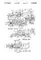
- FIG. 1shows a steering mechanism of the invention.
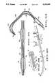
- FIG. 2is an enlarged perspective view of a portion of the mechanism of FIG. 1.
- FIG. 3is an enlarged perspective view similar to FIG. 2, showing a different position for the mechanism.
- FIG. 4is a sectional view of the mechanism of FIG. 1 in yet another position.
- FIG. 5is a sectional view taken along line 5--5 of FIG. 4.
- FIG. 6is a sectional view taken along line 6--6 of FIG. 1.
- FIG. 7is a perspective view of an alternative embodiment of the invention.
- FIG. 8is a sectional view of a distal end of the embodiment of FIG. 7.
- FIG. 9is a sectional view taken along line 9--9 of FIG. 7.
- FIG. 10is a sectional view taken along line 10--10 of FIG. 9.
- FIG. 11is a perspective view of another embodiment of the invention.
- FIG. 12is a sectional view taken along line 12--12 of FIG. 11.
- FIG. 13is a sectional view taken along line 13--13 of FIG. 12.
- FIG. 14is a perspective view of yet another embodiment of the invention.
- FIG. 15is a sectional view taken along line 15--15 of FIG. 14.
- FIG. 16is a perspective view, partially cut away, of another embodiment of the invention.
- FIG. 17Ais a top view, partly cut away, of the embodiment of FIG. 16.
- FIG. 17Bis a sectional view taken along line 17B--17B of FIG. 17A.
- FIG. 18is a perspective view of another embodiment of the invention.
- FIG. 19is a top view of the embodiment of FIG. 18.
- FIG. 20is a perspective view of another embodiment of the invention.
- FIG. 21is a sectional view of the distal end of the embodiment of FIG. 20.
- FIG. 22is a sectional view like that of FIG. 21, in a straightened position.
- FIG. 23is a top view, partially cut away, of the embodiment of FIG. 20.
- FIG. 24is a sectional view taken along line 24--24 of FIG. 23.
- FIG. 25is a sectional view of an alternative embodiment to the distal end of a steering mechanism of the invention.
- FIG. 26is a sectional view taken along line 26--26 of FIG. 25.
- FIG. 27is a sectional view taken along line 27--27 of FIG. 25.
- FIG. 28is a sectional view taken along line 28--28 of FIG. 25.
- FIG. 29is an exploded view showing detail of a portion of the invention.
- FIG. 30is a sectional view of a portion of the steering mechanism of the invention.
- FIG. 31is a sectional view taken along line 31--31 of FIG. 30.
- FIG. 32is a sectional view taken along line 32--32 of FIG. 30.
- FIGS. 33 and 34are sectional views of an alternative embodiment of the invention.
- FIG. 35shows the embodiment of FIG. 1 in use with a conventional medical catheter.
- FIG. 36shows an alternative embodiment to the distal tip of the invention.
- FIG. 1shows a steering mechanism 10 including a controller 15 with a handle 20.
- a flexible steering shaft 30is attached at its proximal end 40 to the controller 15.
- the shaft 30is formed from any conventional material which is flexible, slightly elastic to tolerate bending without permanent deformation, and biocompatible for applications in the medical field.
- the shaft 30is formed from TEFLON (tetrafluoroethylene) for minimizing friction with other elements of the apparatus.
- the mechanism 10may be used to steer and position many different types of apparatus, and the embodiment shown in FIG. 1 is adapted for use with medical catheters.
- the steering shaft 30is positioned within a lumen 45 of a catheter 40, the distal tip 48 of the catheter 40 is maneuvered to a desired position within a patient's body, and the steering mechanism may then be removed so that the lumen 45 may then be used by the physician for introduction of treatment drugs or the like to the patient.
- the cathetermay include also conventional ports for this purpose, such as ports 41 and 42 shown in FIG. 35 which communicate with one or more additional lumens (not separately shown) within the catheter 40.
- the catheter 40is any standard catheter, such as an angioplasty catheter (for laser angioplasty, balloon angioplasty, or other treatments), a catheter with pacing and/or sensing probes, or indeed any flexible or steerable device which one may wish to introduce into a place which is difficult to reach. Such devices need not be confined to the medical field. Other important applications include the introduction of tools (for inspection, adjustment, or repair) into engines or other machines, and the manipulation of objects in any type of conduit. For inspection purposes, fiber optics may be carried by the catheter 40 or other device. In machine repair and adjustment applications, any convention tool may be attached to the distal end of the steering shaft 30, such as drill bits, clamps, wrenches, grinders, and so on, and these tools may be remotely operated from the controller 15. Thus, although the present embodiments of the invention are described primarily in terms of use with a catheter, the invention has many other applications.
- the steering mechanism 10includes a first sleeve 50, as shown in FIGS. 1 and 6, adjacent which is positioned a second sleeve 60.
- the sleeve 50includes a stop 70 at its interior, as shown in FIG. 6, against which the second sleeve 60 abuts.
- the second sleeve 60has an outer diameter closely matching the inner diameter of the first sleeve 50.
- a third sleeve 80is positioned within a forward portion of the second sleeve 60, and has an outer diameter closely matching the inner diameter of the forward portion.
- the third sleeve 80has an inner diameter closely matching the outer diameter of the steering shaft 30.
- the sleeves 50, 60 and 80are firmly fixed so that they do not move relative to one another. As shown in FIG. 6, the steering shaft 30 is seated against a shoulder 85 of the sleeve 60.
- the sleeve 60acts as a cable or wire retainer for the steering wire 120.
- the sleeves 50, 60 and 80may be of a unitary design.
- the catheter 40includes a proximal end 43 which fits tightly against the sleeves 60 and 80 when the steering shaft 30 is inserted all the way into the lumen 45 and is seated against shoulder 85 shown in FIG. 6.
- the end 43may be attached to the controller 15 by means of a standard Luer lock 44.
- the handle 20 shown in FIGS. 1 and 6is generally cylindrical in shape and includes a forward section 90 (shown in dotted fashion in FIG. 1), a middle section 100, and a rear section 110.
- the forward section 90has an outer diameter closely matching the inner diameter of the first sleeve 50, and is positioned within the sleeve 50 in a slidable fashion.
- the middle section 100has a reduced outer diameter, and the rear section 110 has an outer diameter which is chosen for a comfortable grasp by the hand of the operator.
- the sleeves 50, 60, and 80 and the three sections of the handle 20all include central bores which are coaxially aligned for receiving a steering wire 120, as shown in FIG. 6.
- One end of the wire 120is clamped in position relative to the handle 20 by means of a screw 130, shown in FIG. 1, which is threaded into a bore 140, shown in FIG. 6.
- the steering wire 120includes a distal end 150 which is flattened in the preferred embodiment such that it has a rectangular cross section, and extends into a distal end 160 of the shaft 30.
- a coiled spring or sleeve 170defines a central lumen 180 within the steering shaft 30, in which lumen the steering wire 120 is positioned.
- a ferrule 190is positioned within the shaft 30 immediately distal of, and abutting, the coiled spring 170.
- the ferrule 190includes a central lumen 200, and two slots 210 and 220 (as shown in FIG. 29) which are disposed radially opposite one another, and together form a single transverse slot.
- a flat, flexible lead spring 230is positioned within the slots 210 and 220.
- the lead spring 230includes a tongue 240 on its proximal end, which has a width closely matching the inner diameter of the ferrule 190.
- the lead spring 230also includes a broader portion 250 with an outer diameter closely matching the outer diameter of the ferrule 190.
- the tongue 240FIG. 29
- the proximal end of the broader portion 250abuts the bottom ends of the slots 210 and 220.
- the ferrule 190 and the shaft 30have inner diameters which are substantially greater than the combined thickness 265 of the distal end 150 of the steering wire 120 and the lead spring 230.
- the ferrule 190may be omitted, in which case the lead spring 230 is inserted into the coiled spring 170 in much the same fashion as into the ferrule 190, with the same dimensions applying to this embodiment.
- the lead spring 230may be attached to the coiled spring 170 by adhesive, solder, welds, or the like.
- the middle section 100 of the handle 20includes a transverse slot therethrough, into which a control wedge 270 is positioned.
- the wedge 270includes a larger end 280 tapering towards a smaller end 290.
- the wedge 270also includes a slot 300 extending most of its length, as shown in FIGS. 1 and 6.
- the wedge 270is positioned such that the wire 120 passes through the slot 300, as shown in FIG. 6, in which position the slot 300 is generally parallel to the longitudinal axis of the handle 20, and also is parallel to the proximal end of the wire 120.
- the ends 280 and 290which form the ends of the slot 300, prevent the wedge 270 from accidental removal.
- the wire 120is thus pulled toward the right from the point of view of FIGS. 1-4 and 6, and thereby pulls the lead spring 230 at the weld 260, as shown in FIG. 3. This bends the lead spring 230 in the direction of the distal end 150 of the wire 120, thus bending the distal end 160 of the shaft 30, as shown in FIGS. 2 through 4.
- the materials for the wedge 270, the handle 20 and the sleeve 50are chosen to provide sufficient friction, such that the wedge 270 maintains its position wherever it is located by the operator, so that the distal end 160 can be fixed in a variety of positions simply by repositioning the wedge 270.
- the wire 120may be tightened by loosening the screw 130, pulling the wire 120 tight, and then retightening the screw 130, which results in a change in the frictional fit of the wedge 270. Access to the proximal end of the wire 120 may be had through an opening 310 in the rear section of the handle 130.
- the lead spring 230is affixed to the ferrule 190, and the ferrule 190 is in turn affixed to the coiled spring 170.
- Thismay be done by adhesive, welds or the like, and is especially useful in conjunction with a catheter which is to be emplaced permanently or for a long period of time within a patient.
- the ferrulemay alternatively simply be abutted against the coiled spring 170, in which case the distal end 160 of the steering shaft is preferably formed from a heat shrink or other tightly fitting material to maintain the ferrule firmly in place.
- a physicianwill insert the catheter 40 into a patient, such as into the femoral vein, and will insert the shaft 30 into the lumen 45.
- the physiciancan negotiate a path to the treatment site, such as the heart.
- the physicianmay, by operating the control wedge 270, steer past any junction, turn or obstacle which may be presented to the catheter simply by adjusting the control wedge such that the distal end 160 of the shaft 30, and hence also the distal end 48 of the catheter 40, takes on the necessary shape. Once a given obstacle or turn is negotiated by the end 160, it can then again be straightened out by operation of the wedge 270, or may be changed to a different shape as necessary.
- the wedge 270is pushed downward as shown in FIG. 1, such that the distal end 160 takes on the position shown in dotted fashion. If the vein then takes a turn to the left, the physician straightens out the distal end 160, rotates the handle 20 such that the distal end 160 rotates the necessary amount (such as 180°), and then again operates the wedge 270 to manipulate the distal end 160 around the left turn. In this way, complete control over steering and emplacement of the catheter 40 is achieved.
- FIGS. 7-10show an alternative embodiment, wherein left and right turns may be negotiated without rotation of the apparatus.
- the steering mechanism 315 shown in FIG. 7includes a flexible steering shaft 320 having a proximal end 330 and a distal end 340 and may be identical to the shaft 30 shown in FIG. 1.
- a lead spring 350carried within the distal end 340 are a lead spring 350 and two steering wires 360 and 370.
- the steering wires 360 and 370are preferably rounded towards their proximal ends, and flattened towards their distal ends, as with the steering wire 120 shown in FIG. 1.
- the steering wires 360 and 370are attached to the distal end of the lead string 350 by solder, adhesive, spot welds or the like, such as at welds 380 and 390.
- the steering wires 360 and 370(and the steering wires of any of the embodiments described herein) are preferably coated with TEFLON.
- the lead spring 350which may be identical to the lead spring 230 shown in FIG. 2, is seated in a ferrule 400, which is shown in FIG. 8 and may be identical to the ferrule 190 shown in FIG. 2.
- the configuration of the distal end 340 of the shaft 320 shown in FIG. 8is essentially identical to the distal end 160 of the shaft 30 shown in FIG. 2, except that an additional steering wire is attached to the lead spring 350.
- the mechanism 315may be used in the same applications as the mechanism 10.
- FIGS. 25-28show further detail of the distal tip of a steering shaft of the embodiment of FIGS. 7-10, with FIGS. 26, 27 and 28 showing cross-sectional views at the regions indicated in FIG. 25 along the length of the shaft 320.
- the numerals appearing in FIGS. 25-28are the same as those in FIGS. 7 and 8, but the details of these figures may be employed in any of the other embodiments described herein which utilize two steering wires.
- the shaft 320is shown as used in conjunction with the catheter 40 shown in FIG. 35.
- the catheter 40includes a standard braided or other torquable material, and the shaft 320 is adhered to the interior of the catheter 40 by adhesive means such as glue 405 shown in FIGS. 25 and 27.
- adhesive meanssuch as glue 405 shown in FIGS. 25 and 27.
- the shaft 320may be made of a torquable material.
- Distal end 340 of the shaft 320receives the lead spring 350 and the steering wires 360 and 370, as shown in FIG. 25.
- the rounded or circular proximal ends of the steering wires 360 and 370are positioned within a coiled sleeve 375, as shown in FIG. 28.
- the coiled sleeve 375may be a conventional metal coil such as those used in medical catheters to provide longitudinal stiffness but lateral flexibility.
- the steering wires 360 and 370are flattened into a rectangular shape in the region near the lead spring 350.
- the steering wires 360 and 370are attached at several places to the lead spring 350, such as at the three spot welds 380 and the three spot welds 390, respectively, shown in FIG. 25.
- the distal end 340may be a heat-shrink material which, once the elements of the steering mechanism are assembled, is heated to reduce its diameter relative to the main body of the shaft 320, thus tapering the tip in the region of the spot welds 380 and 390, as shown in FIG. 25.
- spot weldsare used to attach the steering wires to the lead spring, the use of heat-shrink is particularly advantageous in applying pressure to the welded region to prevent separation. When solder is used, this is not as important a consideration.
- FIGS. 30-32show an alternative embodiment of the distal end of the invention, wherein the proximal portions of the steering wires 360 and 370 are of noncircular cross section, such as the rectangular cross section shown in this embodiment.
- the steering wires 360 and 370may be further flattened, as shown in FIG. 31, in the region of the lead spring 350, thus providing greater clearance between the combined thickness 385 of the steering wires 360 and 370 and the lead spring 350, on the one hand, and the inner diameters of the ferrule 400 and the shaft 320, on the other hand.
- this clearanceallows greater torque to be placed upon the distal tip of the steering shaft when the physician turns the distal tip by placing tension on the steering wires.
- FIGS. 25-28allows either left or right turns to be effected by pulling on the wire 360 or the wire 370, as shown in dotted fashion for the distal end 340 in FIG. 7.
- FIG. 8shows the configuration of the distal end 340 of the shaft 320 for a right turn, wherein rearward tension is placed on the steering wire 370 (represented by the right-facing arrow), and a forward force is simultaneously applied to the steering wire 360 (as represented by the left-facing arrow).
- the forward force to the wire 360occurs both because of the push given to the wire 360 by the clockwise rotation of the spindle 450 (which is described in greater detail below), and because of the pull exerted by the wire 370 via the welds 390, the lead spring 350, and the welds 380.
- the spindle 450is rotated counterclockwise, force is placed on the steering wires 360 and 370 in directions opposite to the arrows shown in FIG. 8, thus bending the distal end 340 to the left, as shown in dotted fashion.
- a controller 410is provided, as shown in FIGS. 7, 9 and 10.
- the controller 410includes a housing 420 which receives the proximal end 330 of the shaft 320. Attached to the housing 420 is a coupling 430 which has a central bore 440 (shown in dotted fashion in FIG. 9) which is substantially coaxial with the lumen of the shaft 320.
- the guide wires 360 and 370pass through the bore 440, and are attached as shown in FIGS. 9 and 10 to a spindle 450.
- the preferred means of attachmentis by insertion through a bore 460 in the spindle 450, and the proximal tips 470 and 480 of the steering wires 360 and 370, respectively, are bent to prevent retraction through the bore 460.
- the wiresare chosen to be stiff enough that they will retain the bent shape at their proximal tips, and will not retract from the bore 460.
- a taper pin 485may also be used, being driven between the ends 470 and 480 into a frictional fit in a flared portion 465 of the bore 460, thus preventing the proximal tips 470 and 480 from accidental withdrawal.
- the housing 420includes a central passage 490, through which the steering wires 360 and 370 pass, and may include a threaded portion 500 in which an adjustable, threaded tension adjusting screw or bolt 510 is positioned.
- the tension bolt 510includes a central bore 520, as shown in FIG. 10, and a knurled knob 530 for adjustment by hand. As shown in FIG. 7, the knob 530 may be accessed by the operator of the controller 410 at any time, without disassembling the steering mechanism. The knob 530 is turned to adjust tension on the steering wires 360 and 370, and to adjust the amount of play in the lead spring 350, as described in greater detail below.
- the spindle 450is mounted on an axis which is preferably transverse to a longitudinal axis of the housing 420, and is rotatable by means of a steering handle 540, which is connected to the spindle 450 by a shaft 550.
- the spindle 450 and associated steering apparatusare affixed to the housing by means of a plate 552 which is mounted to the housing 420 by means of screws or bolts 554.
- the shaft 550includes a threaded bottom end 560, onto which a tightening knob 570 is threaded.
- a washer 580is preferably positioned between the knob 570 and the housing 420, and a resilient O-ring 590 is positioned adjacent the washer 580. Between the O-ring 590 and the knob 570 is positioned another washer 600.
- the washers 580 and 600 and the O-ring 590are all coaxial with and surrounding the threaded portion 560 of the shaft 550.
- the knob 570is rotated such that it is tightened (i.e., moved closer to the housing 420)
- the increased friction between the knob 570, the washers 580 and 600, the O-ring 590 and the housing 420inhibits the shaft 550 from turning, thereby maintaining the handle 540 in any position set by the operator of the steering mechanism.
- the resiliency of the O-ring 590allows the operator to adjust the friction by means of the knob 570 such that the handle 540 may be relatively easily rotated by pushing with the fingers, and yet such that the distal end 340 will not spring back to the straightened shape shown in FIG.
- knob 570may be loosened such that whenever the operator manipulates the handle 540, and then releases the handle, the distal end 340 is allowed to straighten out--which it will do because of the tension of one or the other of the steering wires, such as the tension due to the steering wire 360 in the position shown in FIG. 8.
- the knob 530is rotated such that it moves to the left from the point of view of FIG. 10 (which will be a counterclockwise rotation for right-hand threads), thereby exerting force on the proximal end 330 of the coiled sleeve 375 (the force being towards the left in FIG. 10).
- the sleeve 330is longitudinally relatively rigid, and thus the force on its proximal end is transmitted to its distal end, where it is exerted in turn on the ferrule 400, and thence onto the lead spring 350.
- the force on the lead spring 350is transmitted to the steering wires 360 and 370 via the welds 380 and 390.
- any longitudinal play in the systemis reduced or eliminated by the counterclockwise rotation of the tension bolt 510, which results in greater responsiveness in the rotational control of the lead spring 350 by means of the steering handle 540.
- FIGS. 7-10therefore, allows the operator of the steering mechanism to manipulate the catheter into whatever position desired, accommodating both left and right turns through the passages encountered in the body.
- the distal end 340 of the shaft 320will need to be rotated 90° to accommodate all possible twists and turns that might be encountered in the body.
- the controller 410may be manipulated entirely with one hand, including both operating the handle 540 to position the distal end 340 into the right and left turn configurations shown in dotted fashion in FIG. 7, and also including axial rotations of the distal end 340 should those become necessary.
- FIGS. 11-13show an alternative embodiment of the invention comprising a steering mechanism 635 which incorporates two steering wires 610 and 620 which extend through a flexible steering shaft 630.
- the portion of the mechanism extending to the left from the point of view of FIG. 11may be identical to the embodiment shown in FIGS. 7 and 8.
- the steering mechanism 635 of FIGS. 11-13includes a controller 640 which constitutes an alternative to the controller 410 shown in FIGS. 7, 9 and 10.
- the controller 640includes a left control wedge 650 and a right control wedge 660 mounted in a housing 670.
- the housing 670includes an opening 680 in which the control wedges 650 and 660 are positioned as shown in FIGS. 11 and 12, with control wedge 650 being tapered upwardly, and control wedge 660 being tapered downwardly.
- the wedges 650 and 660may be identical, except that they are carried in opposite directions in the housing 670.
- Control wedge 650includes a slot 690, and control wedge 660 includes a slot 700. These slots terminate at the upper and lower ends of the control wedges, as shown in FIG. 11.
- the housing 670includes a cavity 710 in which a left control block 720 and a right control block 730 are positioned, such that they may slide to the left and right from the point of view of FIGS. 11-13 (as shown by the double arrows in FIG. 13).
- the left control block 720includes a bore 740
- the right control block 730includes a bore 750, into which the extreme proximal ends of the steering wires 610 and 620 extend, as shown in FIG. 13.
- Screws 760 and 770are provided, as shown in FIGS. 12 and 13, and are threaded into the control blocks 720 and 730 for clamping down the proximal ends of the steering wires 610 and 620.
- the steering wires 610 and 620extend from the steering shaft 630 through a wire retainer 775 and through a bore 780 in the distal end of the housing 670, through the slots 690 and 700, and thence into the bores 740 and 750, where they are held in place by the screws 760 and 770.
- left control block 720is forced to the right from the point of view of FIG. 13, then tension is placed on steering wire 610, thereby turning the distal tip of the steering shaft 630 (and also the distal tip of the catheter in which the shaft is positioned) to the left (as shown in dotted fashion in FIG. 7).
- FIGS. 14 and 15show a controller 790 of the invention which is an alternative to the controller 640 of the embodiment of the invention shown in FIGS. 11-13.
- the controller 790forms a part of a steering mechanism having a distal end which may be identical to the embodiment of FIGS. 7 and 8, or may, as described below, be like the embodiment shown in FIGS. 21 and 22.
- the controller 790includes a housing 800 which receives a steering shaft 810, and also receives steering wires 820 and 830 through a wire retainer 835.
- the housing 800includes flanges 840 and 850 with coaxial bores (such as bore 860) therethrough, with bore 860 being formed through the flange 840 and another bore (not separately shown) being formed through flange 850.
- the boreshave an axis which is substantially at right angles to a longitudinal axis of the housing 800 and the steering shaft 810.
- the controller 790includes a handle 870 having forwardly disposed flanges 880 and 890 which include transverse bores therethrough (not separately shown) which are coaxial with the bores through the flanges 840 and 850. Extending through the bores in the flanges 840, 850, 880 and 890 is a shaft 900 (shown in FIG. 15).
- the shaftincludes an annular bearing 910. As shown in FIG. 15, the steering wires 820 and 830 are disposed on opposite sides of the bearing 910 and are affixed to the handle 870 by means of screws 920 and 930.
- a tightening knob 940(shown in FIG. 14) is coupled to the shaft 900, preferably by threading onto an end thereof, and is used to adjust friction in the same manner as the knob 570 shown in FIG. 9.
- FIGS. 16, 17A and 17Bshow another embodiment of the controller of the invention.
- the controller 950includes a housing 960 having an upper half 970 and a lower half 980. These halves are held together by screws 990.
- the housing 960includes a bore 1000 in its distal end, for receiving a proximal end of a steering shaft 1010, in which steering wires 1020 and 1030 are positioned.
- the portion of the steering shaft 1010 and steering wires 1020 and 1030 to the left of FIG. 16may be identical to the distal portion of the steering shaft shown in FIGS. 7 and 8.
- the housing 960includes a cavity 1040 defined between the two halves 970 and 980, in which a disk 1050 is rotatably mounted, with its axis of rotation defined by a shaft 1060 disposed substantially at right angles to a longitudinal axis of the housing 960.
- the disk 1050includes an upper half 1070 and a lower half 1080, into which are inserted dowels or pins 1090 and 1100.
- the pins 1090 and 1100are received by coaxial bores (not separately shown) in the upper and lower halves 1070 and 1080, respectively.
- the pins 1090 and 1100include heads or tips 1120 and 1130, which protrude above the upper half 1070 of the disk 1050.
- Corresponding arcuate slots 1140 and 1150are provided in the lower surface of the upper half 970 of the housing 960, thus limiting the rotational travel of the disk 1050.
- the steering wires 1020 and 1030are clamped between the upper half 1070 and the lower half 1080.
- Attached to the upper end of the shaft 1060is a knurled knob 1160, onto the lower end of which a nut 1170 is threaded, as shown in FIG. 17B.
- the nut 1170may include a press-nut portion 1110, which has a noncircular cross-section and is press-fit into the lower half 980 of the housing 960, as shown in FIG. 17B. This allows the nut 1170 to be tightened without the use of a wrench.
- the knob 1160is used to adjust the friction imparted by the housing 960 to the disk 1050, in similar fashion to the knob 940 of the controller 790 shown in FIG. 14.
- a tab 1180is formed on a side of the disk 1050, by protruding portions of the upper and lower halves 1070 and 1080.
- the tab 1180forms a grip for the thumb of the operator.
- An additional tab(not separately shown) may be formed diametrically opposite the tab 1180.
- a standard clamp 1200which may include a conventional taper pin (like the taper pin 485 shown in FIG. 10).
- the clamp 1200is tightly received in a flared indentation 1210 formed in one or both of the halves 970 and 980 of the disk 960.
- a tightening screw 1220is preferably threaded into a bore 1230 in the housing 960, by which the tension on the steering wires 1020 and 1030 may be adjusted by screwing the tightening screw 1220 into or out of the bore 1230. This operates in the same fashion as the threaded bolt 510 shown in FIGS. 9 and 10.
- FIGS. 18 and 19depicting a controller 1240 which is an alternative to the controllers described above.
- the controller 1240includes a housing 1250, including an upper half 1260 and a lower half 1270, which are held together by means of screws 1280.
- the housingreceives a steering shaft 1285, in which are disposed steering wires 1290 and 1300.
- the distal portion of the steering shaft 1285may be identical to the distal portion of the shaft 320 shown in FIG. 7.
- the steering wires 1290 and 1300are attached to a rotator 1310, as shown in FIG. 19. Any conventional attachment method may be used, but in the embodiment shown the extreme proximal end of the steering wire 1290 passes through a tapered slot 1320 formed in the rotator 1310, and a wedge or taper pin 1330 is tightly fitted into the slot 1320, thus preventing the steering wire 1290 from slipping out of the slot.
- the steering wire 1300is positioned in a slot 1340 and is maintained in position by a wedge or taper pin 1350. Tension on the steering wires 1290 and 1300 may be adjusted by means of a bolt 1360, just as with the tightening screw 1220 shown in FIG. 17A.
- the rotator 1310is rotatably mounted on a shaft 1370 which is substantially at right angles to a longitudinal axis of the housing 1250 and the longitudinal axis of the steering shaft 1285.
- a slot 1380is formed between the upper and lower housing halves 1260 and 1270, as shown in FIG. 18.
- Finger holes 1390 and 1400are formed by circular portions 1410 and 1420, which are in the preferred embodiment integral with the rotator 1310. This provides ease of operation of the controller 1240.
- a finger hole or thumb hole 1430is formed by a circular portion 1440 formed in the housing 1250.
- the rotator 1310is operated in essentially the same fashion as the disk 1050 shown in FIG. 16, but provides a different type of hand hold for the physician.
- a tightening knob 1450is provided to adjust the friction on the rotator 1310, just as with the knurled knob 1160 of the embodiment of FIG. 16.
- FIGS. 20-24show an alternative embodiment of the invention, including a steering mechanism 1460 including steering wires 1470 and 1480, which terminate in distal tips 1490 and 1500, respectively.
- the steering mechanism 1460includes a housing 1510, and shafts 1520 and 1530 which are transversely, rotatably mounted.
- a disk 1560Carried on the upper end of shaft 1520 is a disk 1560 having an arcuate groove 1570 around its circumference.
- the disk 1560is attached in a non-rotatable fashion to the shaft 1520.
- Mounted in the housing 1510is a stop 1580, for limiting the rotational motion of the disks 1560 and hence of the shaft 1520, with the limit of rotation being determined by the arc length of the groove 1570.
- the shaft 1520is rotated by turning the disk 1560.
- a disk 1590is rigidly attached to the shaft 1530, and includes an arcuate groove 1600 around its perimeter.
- Another stop 1610is mounted in the housing 1510, to limit the rotational motion of the disk 1590 and hence of the shaft 1530.
- Knobs 1540 and 1550are threaded onto the shafts 1520 and 1530, as shown in FIG. 24, and provide rotational friction to the disks 1560 and 1590, respectively, in the same manner as the knob 570 shown in the embodiment of FIG. 7.
- the steering wire 1470is attached to the shaft 1520 by passing the extreme proximal end thereof through a bore 1620 formed in the shaft 1520, and by fixing the proximal tip so that the steering wire 1470 cannot slip relative to the bore 1620.
- steering wire 1480is attached to the shaft 1530 through a bore 1630.
- each of the steering wires to the respective shaftsmay be accomplished by any standard means, such as by wrapping the steering wire around itself, or by welds, adhesives, clamps or the like.
- the steering wires 1470 and 1480are attached to the shafts 1520 and 1530, respectively, by means of conventional taper pins 1632 and 1634, in a friction fit to prevent the wires 1470 and 1480 from accidentally coming loose.
- the steering wire 1470is attached to the extreme distal tip of a lead spring 1640 carried within a steering shaft 1650.
- the lead springis positioned within a slot of a ferrule 1660.
- the configuration of the lead spring 1640, the ferrule 1660, and the attachment of the steering wire 1470 to the lead spring 1640may be identical to the configuration of lead spring 350, ferrule 400, and steering wire 360 shown in FIG. 8.
- the lead spring 1640is held in place relative to the steering shaft 1650 by means of an adhesive 1670.
- the adhesive 1670may include an electrically conductive material, if the steering shaft 1650 is to be utilized in an embodiment wherein an electrode is desired at the tip of the steering shaft.
- the steering wire 1480is attached at its distal tip to the lead spring 1640 at a point somewhat removed from the distal tip thereof, as shown in FIGS. 21 and 22.
- rotation of the shaft 1520 so as to place tension on the steering wire 1470will cause the extreme distal tip of the steering shaft 1650 to turn to the left, while placing tension on the steering wire 1480 (by rotating the shaft 1530) will cause the steering shaft 1650 to turn to the right at the point of attachment of the steering wire 1480 to the lead spring 1640.
- FIG. 21Such a configuration is shown in FIG. 21.
- This embodimenthas several advantages. For instance, tortuous paths may be negotiated by the tip of the steering shaft 1650 by operation of the knobs 1560 and 1590 while the physician views on a fluoroscope. Also, if the catheter (such as catheter 40 shown in FIG. 35) is to be positioned in a vessel which is complicated in shape, the configuration of FIG. 21, or variations thereon, may be the only way to position the distal tip of the steering shaft 1650 without placing too much stress on internal body structures. Another advantage is that the extreme distal tip of the steering shaft 1650 may be placed in position within the patient, and tension may then be taken off of the steering wire 1470, so that the distal tip of the steering shaft 1650 is free to flex, limited only by the flexibility of the lead spring 1640.
- a bendmay be retained in the portion of the steering shaft 1650 adjacent the attachment of the steering wire 1480 to the lead spring 1640, which is of particular importance where the catheter must make a turn very near the final emplacement point of the distal tip thereof, such as in the human heart.
- the embodiment of FIG. 20may take the hook-shaped configuration shown in FIGS. 20 and 21.
- the offset attachment of the steering wires 1470 and 1480 shown in FIG. 21may also be used with other embodiments of the invention herein, indeed wherever two steering wires are used, such as in the embodiments of FIGS. 7, 11, 13, 16, and 18.
- the hook-shaped configuration of FIG. 21is not achieved.
- flexibility in the guiding of the distal tip of the steering shaftis in each case provided, by allowing bends in the distal tip of the steering shaft to be made at different points along its length, such as at its extreme distal tip and somewhat further back thereof. This provides an extra measure of flexibility over the design of FIG. 1.
- Shapes other than the hook shape of FIG. 21may be achieved with different locations of attachment of the steering wires to the lead spring.
- more than two steering wiresmay be used, if desired, with the various embodiments described herein. For instance, it may be desirable to have two offset steering wires attached to one side of the lead spring and one steering wire attached to the other side of the lead spring, to accommodate a particular configuration of emplacement. Alternatively, it may be useful for particular applications to attach steering wires at different angles circumferentially around a lead spring (which may be oval or polygonal in cross section). Other variations on the number, attachment and positioning of the steering wires may be made, and the shapes of the steering wires and the lead spring may be adapted accordingly.
- a steering shaft 1680includes a distal tip 1690, having regions 1700 and 1710 of enlarged diameter.
- a lead spring 1720is positioned within the distal tip 1690, and has its proximal end mounted in a ferrule 1730.
- a steering wire 1740is attached at its extreme distal tip to the lead spring 1720, such as at weld 1750.
- the configuration of the lead spring 1720, ferrule 1730, and steering wire 1740may be essentially identical to the embodiment of FIG. 2.
- FIG. 34When tension is placed on the steering wire 1730, it will be seen from FIG. 34 that the distal end 1690 of the steering shaft 1680 takes sharp bends in two places, namely in the regions 1700 and 1710. This allows the physician greater flexibility in maneuvering around particular obstructions and negotiating difficult pathways through a vessel in the patient's body.
- Both this embodiment and the embodiment of FIGS. 20-24may be carefully constructed such that the distance between bends and the resultant radii of curvature are adapted for a particular medical or other applications.
- the embodiments of FIGS. 20-24 or 33-34may be custom designed for emplacement within the left ventricle of the heart, given the known shape of the heart. Other adaptations are easily accomplished with these designs.
Landscapes
- Health & Medical Sciences (AREA)
- Life Sciences & Earth Sciences (AREA)
- Engineering & Computer Science (AREA)
- Anesthesiology (AREA)
- Biophysics (AREA)
- Pulmonology (AREA)
- Biomedical Technology (AREA)
- Heart & Thoracic Surgery (AREA)
- Hematology (AREA)
- Animal Behavior & Ethology (AREA)
- General Health & Medical Sciences (AREA)
- Public Health (AREA)
- Veterinary Medicine (AREA)
- Mechanical Engineering (AREA)
- Media Introduction/Drainage Providing Device (AREA)
Abstract
Description
This is a continuation of copending application Ser. No. 07/736,384 filed on Jul. 26, 1991, now abandoned, which is a divisional application of Ser. No. 07/473,667 filed Feb. 2, 1990, now abandoned.
This invention relates to a steering mechanism for use with medical catheters or other devices which need to be positioned in difficult locations.
In many medical procedures, it is necessary to position a catheter at a location within a patient's body. A typical emplacement for the distal end of a catheter might be within a ventricle of the heart, by way of the femoral vein. In so passing a catheter through the femoral vein, it is necessary to avoid obstructions, vessel junctions and like, and to make sharp turns to position the distal end of the catheter within the ventricle. Other medical procedures involve similar difficulties in placing a catheter.
In conventional catheters used today, the tip of the catheter may be bent, or may include a stylet which is bent, such that a semipermanent curve is given to the distal end of the catheter so that a physician may guide the distal end thereof towards the treatment location. A disadvantage with this type of apparatus is that the curvature of the bend is not adjustable while the catheter is in the body, and any change in the curvature requires the physician to remove the catheter and reshape the distal end.
There is a need for a steering mechanism for catheters and other devices wherein the distal end of the device can be manipulated at will from a location outside the patient's body or outside the apparatus in which the device is placed. Accordingly, it is an object of the present invention to provide such a steering mechanism, and in particular to provide such a mechanism which provides a wide range of steerability.
It is another object of the invention to provide such a mechanism which may be completely manipulated with one hand.
It is a further object of the invention to provide such a steering mechanism wherein the distal end of the mechanism may be bent into varying shapes for placement in different positions while the mechanism is in use.
Other objects and advantages will more fully appear in the course of the following discussion.
The steering mechanism of the invention includes a flexible steering shaft attached to a controller. The controller includes a handle with a central bore in which one or more steering wires are carried. The steering shaft includes a flexible coil, at the distal end of which a ferrule is positioned. Mounted on the ferrule is a lead spring, which extends to the distal tip of the steering shaft. The steering wire has a distal end which is welded or otherwise affixed to the distal end of the lead spring. Tension may be placed on the steering wire by manipulating the controller, thus turning the distal end of the steering shaft.
In use, the steering shaft is inserted into a lumen of a catheter, and the controller is manipulated to turn the distal end of the catheter.
In a preferred embodiment, two steering wires are provided, one attached to each side of the lead spring at the distal end of the steering shaft. The two steering wires may be attached at points directly opposite one another on the lead spring, or they may be offset to provide for different configurations of the distal end of the steering shaft when tension is placed on one, the other, or both steering wires.
In one embodiment, the controller includes a wedge mounted transversely to the handle of the controller, the wedge receiving the steering wire and being tapered such that pushing the wedge in one direction places tension on the steering wire, and pushing it in the other direction releases tension from the steering wire. In a two steering wire embodiment, two wedges are provided, positioned such that their tapered portions run opposite to one another, for providing two-way steering of the distal end of the steering shaft.
In another embodiment of the invention, two steering wires may be attached to a rotatable shaft which is mounted on an axis transverse to a longitudinal axis of the handle of the controller. A central knob is attached to the shaft, such that turning it one way places tension on one of the steering wires and turning it the other way places tension on the other steering wire.
In an alternative embodiment of the invention, the two steering wires are attached to two separate rotatable shafts mounted on the controller, and the shafts may be independently rotated for independent control of the steering wires.
In a preferred embodiment of the invention, regions of the steering shaft at the distal end thereof are enlarged in diameter to allow for greater bending of the distal end at those regions.
Variations on these and other embodiments are described below.
FIG. 1 shows a steering mechanism of the invention.
FIG. 2 is an enlarged perspective view of a portion of the mechanism of FIG. 1.
FIG. 3 is an enlarged perspective view similar to FIG. 2, showing a different position for the mechanism.
FIG. 4 is a sectional view of the mechanism of FIG. 1 in yet another position.
FIG. 5 is a sectional view taken alongline 5--5 of FIG. 4.
FIG. 6 is a sectional view taken along line 6--6 of FIG. 1.
FIG. 7 is a perspective view of an alternative embodiment of the invention.
FIG. 8 is a sectional view of a distal end of the embodiment of FIG. 7.
FIG. 9 is a sectional view taken along line 9--9 of FIG. 7.
FIG. 10 is a sectional view taken alongline 10--10 of FIG. 9.
FIG. 11 is a perspective view of another embodiment of the invention.
FIG. 12 is a sectional view taken along line 12--12 of FIG. 11.
FIG. 13 is a sectional view taken alongline 13--13 of FIG. 12.
FIG. 14 is a perspective view of yet another embodiment of the invention.
FIG. 15 is a sectional view taken alongline 15--15 of FIG. 14.
FIG. 16 is a perspective view, partially cut away, of another embodiment of the invention.
FIG. 17A is a top view, partly cut away, of the embodiment of FIG. 16.
FIG. 17B is a sectional view taken alongline 17B--17B of FIG. 17A.
FIG. 18 is a perspective view of another embodiment of the invention.
FIG. 19 is a top view of the embodiment of FIG. 18.
FIG. 20 is a perspective view of another embodiment of the invention.
FIG. 21 is a sectional view of the distal end of the embodiment of FIG. 20.
FIG. 22 is a sectional view like that of FIG. 21, in a straightened position.
FIG. 23 is a top view, partially cut away, of the embodiment of FIG. 20.
FIG. 24 is a sectional view taken alongline 24--24 of FIG. 23.
FIG. 25 is a sectional view of an alternative embodiment to the distal end of a steering mechanism of the invention.
FIG. 26 is a sectional view taken alongline 26--26 of FIG. 25.
FIG. 27 is a sectional view taken alongline 27--27 of FIG. 25.
FIG. 28 is a sectional view taken alongline 28--28 of FIG. 25.
FIG. 29 is an exploded view showing detail of a portion of the invention.
FIG. 30 is a sectional view of a portion of the steering mechanism of the invention.
FIG. 31 is a sectional view taken alongline 31--31 of FIG. 30.
FIG. 32 is a sectional view taken alongline 32--32 of FIG. 30.
FIGS. 33 and 34 are sectional views of an alternative embodiment of the invention.
FIG. 35 shows the embodiment of FIG. 1 in use with a conventional medical catheter.
FIG. 36 shows an alternative embodiment to the distal tip of the invention.
FIG. 1 shows asteering mechanism 10 including acontroller 15 with ahandle 20. Aflexible steering shaft 30 is attached at itsproximal end 40 to thecontroller 15. Theshaft 30 is formed from any conventional material which is flexible, slightly elastic to tolerate bending without permanent deformation, and biocompatible for applications in the medical field. Preferably, theshaft 30 is formed from TEFLON (tetrafluoroethylene) for minimizing friction with other elements of the apparatus.
Themechanism 10 may be used to steer and position many different types of apparatus, and the embodiment shown in FIG. 1 is adapted for use with medical catheters. As shown in FIG. 35, the steeringshaft 30 is positioned within alumen 45 of acatheter 40, thedistal tip 48 of thecatheter 40 is maneuvered to a desired position within a patient's body, and the steering mechanism may then be removed so that thelumen 45 may then be used by the physician for introduction of treatment drugs or the like to the patient. The catheter may include also conventional ports for this purpose, such asports 41 and 42 shown in FIG. 35 which communicate with one or more additional lumens (not separately shown) within thecatheter 40.
Thecatheter 40 is any standard catheter, such as an angioplasty catheter (for laser angioplasty, balloon angioplasty, or other treatments), a catheter with pacing and/or sensing probes, or indeed any flexible or steerable device which one may wish to introduce into a place which is difficult to reach. Such devices need not be confined to the medical field. Other important applications include the introduction of tools (for inspection, adjustment, or repair) into engines or other machines, and the manipulation of objects in any type of conduit. For inspection purposes, fiber optics may be carried by thecatheter 40 or other device. In machine repair and adjustment applications, any convention tool may be attached to the distal end of the steeringshaft 30, such as drill bits, clamps, wrenches, grinders, and so on, and these tools may be remotely operated from thecontroller 15. Thus, although the present embodiments of the invention are described primarily in terms of use with a catheter, the invention has many other applications.
In the course of the following discussion, it will be understood that the manipulation, steering or positioning of the shaft 30 (or other shafts of the alternative embodiments) results in concomitant manipulation, steering or positioning of the catheter or other device with which the steering mechanism is used. Any of the following embodiments may be used with thecatheter 40 shown in FIG. 35 or other steerable device.
Thesteering mechanism 10 includes afirst sleeve 50, as shown in FIGS. 1 and 6, adjacent which is positioned asecond sleeve 60. Thesleeve 50 includes astop 70 at its interior, as shown in FIG. 6, against which thesecond sleeve 60 abuts. Thesecond sleeve 60 has an outer diameter closely matching the inner diameter of thefirst sleeve 50.
Athird sleeve 80 is positioned within a forward portion of thesecond sleeve 60, and has an outer diameter closely matching the inner diameter of the forward portion. Thethird sleeve 80 has an inner diameter closely matching the outer diameter of the steeringshaft 30. Thesleeves shaft 30 is seated against ashoulder 85 of thesleeve 60. Thesleeve 60 acts as a cable or wire retainer for thesteering wire 120.
Alternatively, for ease of manufacture thesleeves
As shown in FIG. 35, thecatheter 40 includes a proximal end 43 which fits tightly against thesleeves shaft 30 is inserted all the way into thelumen 45 and is seated againstshoulder 85 shown in FIG. 6. The end 43 may be attached to thecontroller 15 by means of astandard Luer lock 44.
Thehandle 20 shown in FIGS. 1 and 6 is generally cylindrical in shape and includes a forward section 90 (shown in dotted fashion in FIG. 1), amiddle section 100, and arear section 110. Theforward section 90 has an outer diameter closely matching the inner diameter of thefirst sleeve 50, and is positioned within thesleeve 50 in a slidable fashion. Themiddle section 100 has a reduced outer diameter, and therear section 110 has an outer diameter which is chosen for a comfortable grasp by the hand of the operator.
Thesleeves handle 20 all include central bores which are coaxially aligned for receiving asteering wire 120, as shown in FIG. 6. One end of thewire 120 is clamped in position relative to thehandle 20 by means of a screw 130, shown in FIG. 1, which is threaded into abore 140, shown in FIG. 6.
Thesteering wire 120 includes adistal end 150 which is flattened in the preferred embodiment such that it has a rectangular cross section, and extends into adistal end 160 of theshaft 30. A coiled spring orsleeve 170 defines acentral lumen 180 within the steeringshaft 30, in which lumen thesteering wire 120 is positioned. Aferrule 190 is positioned within theshaft 30 immediately distal of, and abutting, thecoiled spring 170. Theferrule 190 includes acentral lumen 200, and twoslots 210 and 220 (as shown in FIG. 29) which are disposed radially opposite one another, and together form a single transverse slot.
A flat,flexible lead spring 230 is positioned within theslots lead spring 230 includes atongue 240 on its proximal end, which has a width closely matching the inner diameter of theferrule 190. Thelead spring 230 also includes abroader portion 250 with an outer diameter closely matching the outer diameter of theferrule 190. Thus, when thelead spring 230 is positioned as shown in FIGS. 2 and 3, the tongue 240 (FIG. 29) is within theferrule 190, and the proximal end of thebroader portion 250 abuts the bottom ends of theslots ferrule 190 andlead spring 230 in the position shown in FIG. 1, thedistal end 150 of thesteering wire 120 is welded or otherwise attached to thelead spring 230, such as atweld 260.
As shown in FIG. 5, theferrule 190 and theshaft 30 have inner diameters which are substantially greater than the combinedthickness 265 of thedistal end 150 of thesteering wire 120 and thelead spring 230.
In an alternative embodiment, shown in FIG. 36, theferrule 190 may be omitted, in which case thelead spring 230 is inserted into thecoiled spring 170 in much the same fashion as into theferrule 190, with the same dimensions applying to this embodiment. Thelead spring 230 may be attached to thecoiled spring 170 by adhesive, solder, welds, or the like.
Referring now to FIGS. 1 and 6, themiddle section 100 of thehandle 20 includes a transverse slot therethrough, into which acontrol wedge 270 is positioned. Thewedge 270 includes alarger end 280 tapering towards asmaller end 290. Thewedge 270 also includes aslot 300 extending most of its length, as shown in FIGS. 1 and 6. Thewedge 270 is positioned such that thewire 120 passes through theslot 300, as shown in FIG. 6, in which position theslot 300 is generally parallel to the longitudinal axis of thehandle 20, and also is parallel to the proximal end of thewire 120. The ends 280 and 290, which form the ends of theslot 300, prevent thewedge 270 from accidental removal.
When thewedge 270 is in the upper position shown in FIGS. 1 and 6, thedistal end 160 of theshaft 30 has the configuration shown in FIG. 2. However, when thewedge 270 is pushed downward to the position shown in dotted fashion in FIGS. 1 and 6, this forces thefirst sleeve 50 forwardly relative to thehandle 20, by increasing the distance therebetween. Alternatively speaking, thehandle 20 is forced rearwardly relative to thesleeve 50, into the position shown in dotted fashion (at the extreme right end) in FIGS. 1 and 6. The proximal end of thewire 120, being affixed by the screw 130, is similarly moved towards the right from the point of view of FIG. 6, to the position shown in dotted fashion.
Thewire 120 is thus pulled toward the right from the point of view of FIGS. 1-4 and 6, and thereby pulls thelead spring 230 at theweld 260, as shown in FIG. 3. This bends thelead spring 230 in the direction of thedistal end 150 of thewire 120, thus bending thedistal end 160 of theshaft 30, as shown in FIGS. 2 through 4.
It will be appreciated that, because of the relatively large inner diameters of theferrule 190 and theshaft 30, lateral torque or leverage may be exerted by thedistal end 150 on thelead spring 230, in order to effect bending of thedistal end 160 of theshaft 30. Thus, by providing enough radial play to thedistal end 150 of thewire 120 and thelead spring 230, sufficient torque for steering thedistal end 160 may be assured. The amount of radial play may be determined empirically for a given application, but in most cases a minimum inner diameter of thelead spring 230 and theshaft 30 of approximately two to three times the combined thickness 165 shown in FIG. 5 will be sufficient to provide the necessary torque.
The materials for thewedge 270, thehandle 20 and thesleeve 50 are chosen to provide sufficient friction, such that thewedge 270 maintains its position wherever it is located by the operator, so that thedistal end 160 can be fixed in a variety of positions simply by repositioning thewedge 270. Thewire 120 may be tightened by loosening the screw 130, pulling thewire 120 tight, and then retightening the screw 130, which results in a change in the frictional fit of thewedge 270. Access to the proximal end of thewire 120 may be had through anopening 310 in the rear section of the handle 130.
In the preferred embodiment, thelead spring 230 is affixed to theferrule 190, and theferrule 190 is in turn affixed to thecoiled spring 170. This may be done by adhesive, welds or the like, and is especially useful in conjunction with a catheter which is to be emplaced permanently or for a long period of time within a patient. The ferrule may alternatively simply be abutted against thecoiled spring 170, in which case thedistal end 160 of the steering shaft is preferably formed from a heat shrink or other tightly fitting material to maintain the ferrule firmly in place.
In use, a physician will insert thecatheter 40 into a patient, such as into the femoral vein, and will insert theshaft 30 into thelumen 45. By manipulating thedistal end 160 as necessary and pushing on thehandle 20, the physician can negotiate a path to the treatment site, such as the heart. The physician may, by operating thecontrol wedge 270, steer past any junction, turn or obstacle which may be presented to the catheter simply by adjusting the control wedge such that thedistal end 160 of theshaft 30, and hence also thedistal end 48 of thecatheter 40, takes on the necessary shape. Once a given obstacle or turn is negotiated by theend 160, it can then again be straightened out by operation of thewedge 270, or may be changed to a different shape as necessary. If, for instance, the physician encounters a turn of the vein towards the right, thewedge 270 is pushed downward as shown in FIG. 1, such that thedistal end 160 takes on the position shown in dotted fashion. If the vein then takes a turn to the left, the physician straightens out thedistal end 160, rotates thehandle 20 such that thedistal end 160 rotates the necessary amount (such as 180°), and then again operates thewedge 270 to manipulate thedistal end 160 around the left turn. In this way, complete control over steering and emplacement of thecatheter 40 is achieved.
FIGS. 7-10 show an alternative embodiment, wherein left and right turns may be negotiated without rotation of the apparatus. Thesteering mechanism 315 shown in FIG. 7 includes aflexible steering shaft 320 having aproximal end 330 and adistal end 340 and may be identical to theshaft 30 shown in FIG. 1. As shown in FIG. 8, carried within thedistal end 340 are alead spring 350 and twosteering wires steering wires steering wire 120 shown in FIG. 1. Thesteering wires lead string 350 by solder, adhesive, spot welds or the like, such as atwelds steering wires 360 and 370 (and the steering wires of any of the embodiments described herein) are preferably coated with TEFLON.
Thelead spring 350, which may be identical to thelead spring 230 shown in FIG. 2, is seated in aferrule 400, which is shown in FIG. 8 and may be identical to theferrule 190 shown in FIG. 2. Thus, the configuration of thedistal end 340 of theshaft 320 shown in FIG. 8 is essentially identical to thedistal end 160 of theshaft 30 shown in FIG. 2, except that an additional steering wire is attached to thelead spring 350. Themechanism 315 may be used in the same applications as themechanism 10.
FIGS. 25-28 show further detail of the distal tip of a steering shaft of the embodiment of FIGS. 7-10, with FIGS. 26, 27 and 28 showing cross-sectional views at the regions indicated in FIG. 25 along the length of theshaft 320. The numerals appearing in FIGS. 25-28 are the same as those in FIGS. 7 and 8, but the details of these figures may be employed in any of the other embodiments described herein which utilize two steering wires.
In FIGS. 25-28, theshaft 320 is shown as used in conjunction with thecatheter 40 shown in FIG. 35. Preferably, thecatheter 40 includes a standard braided or other torquable material, and theshaft 320 is adhered to the interior of thecatheter 40 by adhesive means such asglue 405 shown in FIGS. 25 and 27. With this configuration, torque on the proximal end of thecatheter 40 will be transmitted to its distal end, and via theglue 405 will be transmitted to theshaft 320, thus allowing for turning of thedistal end 340. Alternatively, and especially in embodiments wherein no catheter is used, theshaft 320 may be made of a torquable material.
In the preferred embodiment, thesteering wires lead spring 350, such as at the threespot welds 380 and the threespot welds 390, respectively, shown in FIG. 25. Thedistal end 340 may be a heat-shrink material which, once the elements of the steering mechanism are assembled, is heated to reduce its diameter relative to the main body of theshaft 320, thus tapering the tip in the region of thespot welds
FIGS. 30-32 show an alternative embodiment of the distal end of the invention, wherein the proximal portions of thesteering wires steering wires lead spring 350, thus providing greater clearance between the combinedthickness 385 of thesteering wires lead spring 350, on the one hand, and the inner diameters of theferrule 400 and theshaft 320, on the other hand. As discussed above relative to FIGS. 1-5 (and as shown in FIG. 5), this clearance allows greater torque to be placed upon the distal tip of the steering shaft when the physician turns the distal tip by placing tension on the steering wires.
Referring again to FIGS. 7-10, it will be seen that the configuration shown in FIGS. 25-28 (or 30-32) allows either left or right turns to be effected by pulling on thewire 360 or thewire 370, as shown in dotted fashion for thedistal end 340 in FIG. 7. FIG. 8 shows the configuration of thedistal end 340 of theshaft 320 for a right turn, wherein rearward tension is placed on the steering wire 370 (represented by the right-facing arrow), and a forward force is simultaneously applied to the steering wire 360 (as represented by the left-facing arrow). The forward force to thewire 360 occurs both because of the push given to thewire 360 by the clockwise rotation of the spindle 450 (which is described in greater detail below), and because of the pull exerted by thewire 370 via thewelds 390, thelead spring 350, and thewelds 380. When thespindle 450 is rotated counterclockwise, force is placed on thesteering wires distal end 340 to the left, as shown in dotted fashion.
In order to provide such tension to the steering wires, acontroller 410 is provided, as shown in FIGS. 7, 9 and 10. Thecontroller 410 includes ahousing 420 which receives theproximal end 330 of theshaft 320. Attached to thehousing 420 is acoupling 430 which has a central bore 440 (shown in dotted fashion in FIG. 9) which is substantially coaxial with the lumen of theshaft 320.
Theguide wires bore 440, and are attached as shown in FIGS. 9 and 10 to aspindle 450. The preferred means of attachment is by insertion through abore 460 in thespindle 450, and theproximal tips steering wires bore 460. The wires are chosen to be stiff enough that they will retain the bent shape at their proximal tips, and will not retract from thebore 460. Optionally, a taper pin 485 may also be used, being driven between theends portion 465 of thebore 460, thus preventing theproximal tips
Thehousing 420 includes acentral passage 490, through which thesteering wires portion 500 in which an adjustable, threaded tension adjusting screw or bolt 510 is positioned. Thetension bolt 510 includes a central bore 520, as shown in FIG. 10, and aknurled knob 530 for adjustment by hand. As shown in FIG. 7, theknob 530 may be accessed by the operator of thecontroller 410 at any time, without disassembling the steering mechanism. Theknob 530 is turned to adjust tension on thesteering wires lead spring 350, as described in greater detail below.
Thespindle 450 is mounted on an axis which is preferably transverse to a longitudinal axis of thehousing 420, and is rotatable by means of asteering handle 540, which is connected to thespindle 450 by ashaft 550. Thespindle 450 and associated steering apparatus are affixed to the housing by means of aplate 552 which is mounted to thehousing 420 by means of screws orbolts 554.
Theshaft 550 includes a threadedbottom end 560, onto which a tighteningknob 570 is threaded. Awasher 580 is preferably positioned between theknob 570 and thehousing 420, and a resilient O-ring 590 is positioned adjacent thewasher 580. Between the O-ring 590 and theknob 570 is positioned anotherwasher 600.
Thewashers ring 590 are all coaxial with and surrounding the threadedportion 560 of theshaft 550. Thus, when theknob 570 is rotated such that it is tightened (i.e., moved closer to the housing 420), the increased friction between theknob 570, thewashers ring 590 and thehousing 420 inhibits theshaft 550 from turning, thereby maintaining thehandle 540 in any position set by the operator of the steering mechanism. The resiliency of the O-ring 590 allows the operator to adjust the friction by means of theknob 570 such that thehandle 540 may be relatively easily rotated by pushing with the fingers, and yet such that thedistal end 340 will not spring back to the straightened shape shown in FIG. 7 (which would cause the handle 542 spring back to the central position shown in FIG. 7) when the operator releases thehandle 540. Alternatively, theknob 570 may be loosened such that whenever the operator manipulates thehandle 540, and then releases the handle, thedistal end 340 is allowed to straighten out--which it will do because of the tension of one or the other of the steering wires, such as the tension due to thesteering wire 360 in the position shown in FIG. 8.
In order to increase the tension in thesteering wires handle 540, theknob 530 is rotated such that it moves to the left from the point of view of FIG. 10 (which will be a counterclockwise rotation for right-hand threads), thereby exerting force on theproximal end 330 of the coiled sleeve 375 (the force being towards the left in FIG. 10). Thesleeve 330 is longitudinally relatively rigid, and thus the force on its proximal end is transmitted to its distal end, where it is exerted in turn on theferrule 400, and thence onto thelead spring 350. The force on thelead spring 350 is transmitted to thesteering wires welds tension bolt 510, which results in greater responsiveness in the rotational control of thelead spring 350 by means of thesteering handle 540.
Conversely, tension on the steering wires is reduced, and greater play is given to the steering function, by rotating theknob 530 such that it moves towards the right from the point of view of FIG. 10.
The embodiment of FIGS. 7-10, therefore, allows the operator of the steering mechanism to manipulate the catheter into whatever position desired, accommodating both left and right turns through the passages encountered in the body. At most, thedistal end 340 of theshaft 320 will need to be rotated 90° to accommodate all possible twists and turns that might be encountered in the body. Thecontroller 410 may be manipulated entirely with one hand, including both operating thehandle 540 to position thedistal end 340 into the right and left turn configurations shown in dotted fashion in FIG. 7, and also including axial rotations of thedistal end 340 should those become necessary.
FIGS. 11-13 show an alternative embodiment of the invention comprising asteering mechanism 635 which incorporates twosteering wires flexible steering shaft 630. The portion of the mechanism extending to the left from the point of view of FIG. 11 may be identical to the embodiment shown in FIGS. 7 and 8. Thesteering mechanism 635 of FIGS. 11-13 includes acontroller 640 which constitutes an alternative to thecontroller 410 shown in FIGS. 7, 9 and 10.
Thecontroller 640 includes aleft control wedge 650 and aright control wedge 660 mounted in ahousing 670. Thehousing 670 includes anopening 680 in which thecontrol wedges control wedge 650 being tapered upwardly, andcontrol wedge 660 being tapered downwardly. Thewedges housing 670.
Thehousing 670 includes acavity 710 in which aleft control block 720 and a right control block 730 are positioned, such that they may slide to the left and right from the point of view of FIGS. 11-13 (as shown by the double arrows in FIG. 13). Theleft control block 720 includes abore 740, and theright control block 730 includes abore 750, into which the extreme proximal ends of thesteering wires Screws 760 and 770 are provided, as shown in FIGS. 12 and 13, and are threaded into the control blocks 720 and 730 for clamping down the proximal ends of thesteering wires
As shown in FIGS. 11-13, thesteering wires shaft 630 through awire retainer 775 and through abore 780 in the distal end of thehousing 670, through theslots bores screws 760 and 770. Thus, ifleft control block 720 is forced to the right from the point of view of FIG. 13, then tension is placed onsteering wire 610, thereby turning the distal tip of the steering shaft 630 (and also the distal tip of the catheter in which the shaft is positioned) to the left (as shown in dotted fashion in FIG. 7). Likewise, ifright control block 730 is forced to the right, tension is placed on thesteering wire 620, forcing the distal tip of the steering shaft 630 (and the distal tip of the catheter) to the right. Again, only one hand is needed to operate thecontroller 640, and at most a 90° turn of the distal tip of thesteering shaft 630 will be required to negotiate all twists and turns within the passages in the body of a patient. As will be discussed in further detail below, thecontroller 640 of FIGS. 11-13 has particular advantages when used with a distal tip of the configuration shown in FIGS. 21 and 22.
FIGS. 14 and 15 show acontroller 790 of the invention which is an alternative to thecontroller 640 of the embodiment of the invention shown in FIGS. 11-13. Thecontroller 790 forms a part of a steering mechanism having a distal end which may be identical to the embodiment of FIGS. 7 and 8, or may, as described below, be like the embodiment shown in FIGS. 21 and 22.
Thecontroller 790 includes ahousing 800 which receives asteering shaft 810, and also receives steeringwires wire retainer 835.
Thehousing 800 includesflanges bore 860 being formed through theflange 840 and another bore (not separately shown) being formed throughflange 850. The bores have an axis which is substantially at right angles to a longitudinal axis of thehousing 800 and thesteering shaft 810. Thecontroller 790 includes ahandle 870 having forwardly disposedflanges flanges flanges steering wires handle 870 by means ofscrews shaft 900, preferably by threading onto an end thereof, and is used to adjust friction in the same manner as theknob 570 shown in FIG. 9.
When thehandle 870 is pulled to the left, as shown in dotted fashion in the lower portion of FIG. 15, rearward tension is placed on thesteering wire 830 and a forward force is exerted on thesteering wire 820. This causes the distal tip of the steering shaft to bend to the right, as shown in dotted fashion on the upper side of thesteering shaft 320 in FIG. 7. Conversely, when thehandle 870 is pushed to the right with respect to thehousing 840, as shown in dotted fashion in the upper portion of FIG. 15, rearward tension is placed on thesteering wire 820 and a forward force is exerted on thesteering wire 830, causing the distal tip of the steering shaft to bend to the left, as shown in dotted fashion on the lower side of thesteering shaft 320 in FIG. 7. As with the embodiment of FIG. 9, theknob 570 may be tightened such that thehandle 870 will maintain whatever position it is placed in, or it may be loosened to allow much freer play to thehandle 870.
FIGS. 16, 17A and 17B show another embodiment of the controller of the invention. Thecontroller 950 includes ahousing 960 having anupper half 970 and alower half 980. These halves are held together byscrews 990. Thehousing 960 includes abore 1000 in its distal end, for receiving a proximal end of asteering shaft 1010, in whichsteering wires steering shaft 1010 andsteering wires
Thehousing 960 includes acavity 1040 defined between the twohalves disk 1050 is rotatably mounted, with its axis of rotation defined by ashaft 1060 disposed substantially at right angles to a longitudinal axis of thehousing 960. Thedisk 1050 includes anupper half 1070 and alower half 1080, into which are inserted dowels orpins pins lower halves pins tips 1120 and 1130, which protrude above theupper half 1070 of thedisk 1050. Correspondingarcuate slots upper half 970 of thehousing 960, thus limiting the rotational travel of thedisk 1050.
Thesteering wires upper half 1070 and thelower half 1080. Attached to the upper end of theshaft 1060 is aknurled knob 1160, onto the lower end of which anut 1170 is threaded, as shown in FIG. 17B. Thenut 1170 may include a press-nut portion 1110, which has a noncircular cross-section and is press-fit into thelower half 980 of thehousing 960, as shown in FIG. 17B. This allows thenut 1170 to be tightened without the use of a wrench.
Theknob 1160 is used to adjust the friction imparted by thehousing 960 to thedisk 1050, in similar fashion to theknob 940 of thecontroller 790 shown in FIG. 14.
Atab 1180 is formed on a side of thedisk 1050, by protruding portions of the upper andlower halves tab 1180 forms a grip for the thumb of the operator. An additional tab (not separately shown) may be formed diametrically opposite thetab 1180.
The extreme proximal ends of thesteering wires bearing 1190 by means of astandard clamp 1200, which may include a conventional taper pin (like the taper pin 485 shown in FIG. 10). Theclamp 1200 is tightly received in a flaredindentation 1210 formed in one or both of thehalves disk 960.
Thus, as thetab 1180 is pushed clockwise from the point of view of FIG. 17A, rearward tension is placed on thesteering wire 1030, and a forward force is exerted on thesteering wire 1020. The distal tip of thesteering shaft 1010 is thus turned to the right, as described previously with respect to thesteering shaft 320 shown in FIG. 7. Pushing on thetab 1180 counterclockwise from the point of view of FIG. 17A likewise turns the distal tip of thesteering shaft 1010 to the left.
A tightening screw 1220 is preferably threaded into abore 1230 in thehousing 960, by which the tension on thesteering wires bore 1230. This operates in the same fashion as the threadedbolt 510 shown in FIGS. 9 and 10.
Another embodiment of the invention is shown in FIGS. 18 and 19, depicting acontroller 1240 which is an alternative to the controllers described above. Thecontroller 1240 includes ahousing 1250, including anupper half 1260 and alower half 1270, which are held together by means ofscrews 1280. The housing receives asteering shaft 1285, in which are disposedsteering wires steering shaft 1285 may be identical to the distal portion of theshaft 320 shown in FIG. 7.
Thesteering wires rotator 1310, as shown in FIG. 19. Any conventional attachment method may be used, but in the embodiment shown the extreme proximal end of thesteering wire 1290 passes through a taperedslot 1320 formed in therotator 1310, and a wedge ortaper pin 1330 is tightly fitted into theslot 1320, thus preventing thesteering wire 1290 from slipping out of the slot. Likewise, thesteering wire 1300 is positioned in aslot 1340 and is maintained in position by a wedge ortaper pin 1350. Tension on thesteering wires bolt 1360, just as with the tightening screw 1220 shown in FIG. 17A.
Therotator 1310 is rotatably mounted on ashaft 1370 which is substantially at right angles to a longitudinal axis of thehousing 1250 and the longitudinal axis of thesteering shaft 1285. Aslot 1380 is formed between the upper andlower housing halves steering shaft 1285 to the left or right by rotating therotator 1310 counterclockwise or clockwise, respectively.Finger holes circular portions 1410 and 1420, which are in the preferred embodiment integral with therotator 1310. This provides ease of operation of thecontroller 1240. Likewise, a finger hole orthumb hole 1430 is formed by acircular portion 1440 formed in thehousing 1250.
Therotator 1310 is operated in essentially the same fashion as thedisk 1050 shown in FIG. 16, but provides a different type of hand hold for the physician. A tighteningknob 1450 is provided to adjust the friction on therotator 1310, just as with theknurled knob 1160 of the embodiment of FIG. 16.
FIGS. 20-24 show an alternative embodiment of the invention, including asteering mechanism 1460 includingsteering wires distal tips steering mechanism 1460 includes ahousing 1510, andshafts
Carried on the upper end ofshaft 1520 is adisk 1560 having anarcuate groove 1570 around its circumference. Thedisk 1560 is attached in a non-rotatable fashion to theshaft 1520. Mounted in thehousing 1510 is astop 1580, for limiting the rotational motion of thedisks 1560 and hence of theshaft 1520, with the limit of rotation being determined by the arc length of thegroove 1570. Theshaft 1520 is rotated by turning thedisk 1560.
Similarly, adisk 1590 is rigidly attached to theshaft 1530, and includes anarcuate groove 1600 around its perimeter. Anotherstop 1610 is mounted in thehousing 1510, to limit the rotational motion of thedisk 1590 and hence of theshaft 1530.
As shown in FIG. 23, thesteering wire 1470 is attached to theshaft 1520 by passing the extreme proximal end thereof through a bore 1620 formed in theshaft 1520, and by fixing the proximal tip so that thesteering wire 1470 cannot slip relative to the bore 1620. Similarly,steering wire 1480 is attached to theshaft 1530 through abore 1630.
Affixation of each of the steering wires to the respective shafts may be accomplished by any standard means, such as by wrapping the steering wire around itself, or by welds, adhesives, clamps or the like. In a preferred embodiment, thesteering wires shafts conventional taper pins wires
In the embodiment of FIGS. 20-24, thesteering wire 1470 is attached to the extreme distal tip of alead spring 1640 carried within asteering shaft 1650. The lead spring is positioned within a slot of aferrule 1660. The configuration of thelead spring 1640, theferrule 1660, and the attachment of thesteering wire 1470 to thelead spring 1640 may be identical to the configuration oflead spring 350,ferrule 400, andsteering wire 360 shown in FIG. 8. Thelead spring 1640 is held in place relative to thesteering shaft 1650 by means of an adhesive 1670. The adhesive 1670 may include an electrically conductive material, if thesteering shaft 1650 is to be utilized in an embodiment wherein an electrode is desired at the tip of the steering shaft.
In this embodiment, thesteering wire 1480 is attached at its distal tip to thelead spring 1640 at a point somewhat removed from the distal tip thereof, as shown in FIGS. 21 and 22. With this configuration, rotation of theshaft 1520 so as to place tension on thesteering wire 1470 will cause the extreme distal tip of thesteering shaft 1650 to turn to the left, while placing tension on the steering wire 1480 (by rotating the shaft 1530) will cause thesteering shaft 1650 to turn to the right at the point of attachment of thesteering wire 1480 to thelead spring 1640. Such a configuration is shown in FIG. 21.
This embodiment has several advantages. For instance, tortuous paths may be negotiated by the tip of thesteering shaft 1650 by operation of theknobs catheter 40 shown in FIG. 35) is to be positioned in a vessel which is complicated in shape, the configuration of FIG. 21, or variations thereon, may be the only way to position the distal tip of thesteering shaft 1650 without placing too much stress on internal body structures. Another advantage is that the extreme distal tip of thesteering shaft 1650 may be placed in position within the patient, and tension may then be taken off of thesteering wire 1470, so that the distal tip of thesteering shaft 1650 is free to flex, limited only by the flexibility of thelead spring 1640. However, at the same time, a bend may be retained in the portion of thesteering shaft 1650 adjacent the attachment of thesteering wire 1480 to thelead spring 1640, which is of particular importance where the catheter must make a turn very near the final emplacement point of the distal tip thereof, such as in the human heart.
Because theknobs steering wires
Shapes other than the hook shape of FIG. 21 may be achieved with different locations of attachment of the steering wires to the lead spring. Also, more than two steering wires may be used, if desired, with the various embodiments described herein. For instance, it may be desirable to have two offset steering wires attached to one side of the lead spring and one steering wire attached to the other side of the lead spring, to accommodate a particular configuration of emplacement. Alternatively, it may be useful for particular applications to attach steering wires at different angles circumferentially around a lead spring (which may be oval or polygonal in cross section). Other variations on the number, attachment and positioning of the steering wires may be made, and the shapes of the steering wires and the lead spring may be adapted accordingly.
Further flexibility may be accomplished by the present invention utilizing the configurations of FIGS. 33 and 34. In this embodiment, asteering shaft 1680 includes adistal tip 1690, havingregions lead spring 1720 is positioned within thedistal tip 1690, and has its proximal end mounted in aferrule 1730. Asteering wire 1740 is attached at its extreme distal tip to thelead spring 1720, such as atweld 1750. The configuration of thelead spring 1720,ferrule 1730, andsteering wire 1740 may be essentially identical to the embodiment of FIG. 2.
When tension is placed on thesteering wire 1730, it will be seen from FIG. 34 that thedistal end 1690 of thesteering shaft 1680 takes sharp bends in two places, namely in theregions
Claims (10)
1. A steering mechanism comprising:
a steering shaft having a proximal end and a distal end and a lumen therethrough;
a coiled spring mounted in the steering shaft and having a distal end that terminates within the steering shaft short of the distal end of the steering shaft, the distal end of the steering shaft being free of any coiled spring;
a lead spring having an axis and a bendable portion extending outside the distal end of coiled spring but still within the distal end of the steering shaft that is free of any coiled spring for bending the distal end of the steering shaft in response to an applied force relative to the coiled spring,
a first steering wire extending through the lumen, having a first end attached to the lead spring a first location outside at the distal end of the coiled spring and having a second end exiting the proximal end;
a second steering wire extending through the lumen, having a third end attached to the lead spring at a second location outside the distal end of the coiled and having a fourth end exiting the proximal end; and
a controller positioned at the proximal end and attached to the second and fourth ends, for placing tension on at least one of the first steering wire and the second steering wire, for applying force to the steering wire to bend the distal end of the steering shaft toward the tensed steering wire.
2. The steering mechanism of claim 1, wherein said first and second attachment locations for said steering wires are longitudinally offset from one another with respect to the axis of said lead spring, for causing a bend at said first location when said first steering wire is tensed, and for causing a bend at said second location when said second steering wire is tensed.
3. The steering mechanism of claim 1, wherein said controller includes:
a housing connected to said steering shaft;
a first shaft rotatably mounted in said housing, with said second end of said first steering wire being attached to said first shaft;
a second shaft rotatably mounted in said housing, with said fourth end of said second steering wire being attached to said second shaft;
first means attached to said first shaft for rotating said first shaft, and second means attached to said second shaft for rotating said second shaft, for placing tension on said first and second steering wires independently of one another.
4. The steering mechanism of claim 3, wherein said first and second attachment locations for said steering wires are on opposite sides of said lead spring from one another and are longitudinally offset, along the axis of the leading for causing a bend at said first location in a first direction when said first steering wire is tensed, and for causing a bend at said second location in a second direction when said second steering wire is tensed.
5. A steerable catheter including
a handle,
a steering shaft having a proximal end attached to the handle and a distal end and a lumen therethrough;
a coiled spring mounted in the steering shaft and having a distal end that terminates within the steering shaft short of the distal end of the steering shaft, the distal end of the steering shaft being free of any coiled spring;
a lead spring having an axis and a bendable portion extending outside the distal end of coiled spring but still within the distal end of the steering shaft that is free of any coiled spring for bending the distal end of the steering shaft in response to an applied force relative to the coiled spring;
a first steering wire extending through the lumen, having a first end attached to the lead spring at a first location outside the distal end of the coiled spring and having a second end exiting the proximal end;
a second steering wire extending through the lumen, having a third end attached to the lead spring at a second location outside the distal end of the coiled spring and having a fourth end exiting the proximal end; and
a controller positioned on the handle and attached to the second and fourth ends, for placing tension on at least one of the first steering wire and the second steering wire, for applying force to the steering wire to bend the distal end of the steering shaft toward the tensed steering wire.
6. A catheter according to claim 5
wherein the first and second attachments for the steering wires are longitudinally offset from one another along the axis of the lead spring.
7. A steering mechanism, including:
a steering shaft having a proximal end and a distal end and a lumen therethrough;
a coiled spring mounted in the steering shaft;
a lead spring positioned within the distal end and fixed relative to the coiled spring;
a first steering wire extending through the lumen, having a first end attached to the lead spring at a first location and having a second end exiting the proximal end;
a second steering wire extending through the lumen, having a third end attached to the lead spring at a second location and having a fourth end exiting the proximal end;
a controller positioned at the proximal end and attached to the second and fourth ends, for placing tension on at least one of the first steering wire and the second steering wire, for causing the distal end to bend toward the tensed steering wire, the controller comprising
a housing connected to the steering shaft;
a first shaft rotatably mounted in the housing, with the second end of the first steering wire being attached to the first shaft;
a second shaft rotatably mounted in the housing, with the fourth end of the second steering wire being attached to the second shaft; and
first means attached to the first shaft for rotating the first shaft, and second means attached to the second shaft for rotating the second shaft, for placing tension on the first and second steering wires independently of one another.
8. The steering mechanism of claim 7, wherein the first and second attachment locations for the steering wires are on opposite sides of the lead spring from one another and are longitudinally offset, for causing a bend at the first location in a fist direction when the first steering wire is tensed, and for causing a bend at the second location in a second direction when the second steering wire is tensed.
9. A steering mechanism comprising:
a steering shaft having a proximal end and a distal end and a lumen therethrough;
a coiled spring mounted in the steering shaft and having a distal end that terminates within the steering shaft short of the distal end of the steering shaft;
a lead spring extending outside the distal end of coiled spring but still within the distal end of the steering shaft for bending the distal end of the steering shaft in response to an applied force relative to the coiled spring;
a first steering wire extending through the lumen, having a first end attached to the lead spring at a first location outside the distal end of the coiled spring and having a second end exiting the proximal end;
a second steering wire extending through the lumen, having a third end attached to the lead spring at a second location outside the distal end of the coiled spring and having a fourth end exiting the proximal end; and
a controller positioned at the proximal end and attached to the second and fourth ends, for placing tension on at least one of the first steering wire and the second steering wire, for applying force to the steering wire to bend the distal end of the steering shaft toward the tensed steering wire, the controller comprising
a housing connected to said steering shaft;
a first shaft rotatably mounted in said housing, with the second end of the first steering wire being attached to the first shaft;
a second shaft rotatably mounted in the housing, with the fourth end of the second steering wire being attached to the second shaft; and
first means attached to the first shaft for rotating the first shaft, and second means attached to the second shaft for rotating the second shaft, for placing tension on the first and second steering wires independently of one another.
10. The steering mechanism of claim 9, wherein the first and second attachment locations for the steering wires are on opposite sides of the lead spring from one another and are longitudinally offset, for causing a bend at the first location in a fist direction when the first steering wire is tensed, and for causing a bend at the second location in a second direction when the second steering wire is tensed.
Priority Applications (13)
| Application Number | Priority Date | Filing Date | Title |
|---|---|---|---|
| US07/991,474US5254088A (en) | 1990-02-02 | 1992-12-16 | Catheter steering mechanism |
| US08/058,319US5358478A (en) | 1990-02-02 | 1993-05-06 | Catheter steering assembly providing asymmetric left and right curve configurations |
| US08/100,555US5336182A (en) | 1990-02-02 | 1993-07-30 | Catheter steering mechanism |
| US08/099,603US5395327A (en) | 1990-02-02 | 1993-07-30 | Catheter steering mechanism |
| US08/363,294US5531686A (en) | 1990-02-02 | 1994-12-23 | Catheter steering mechanism |
| US08/645,456US5820591A (en) | 1990-02-02 | 1996-05-13 | Assemblies for creating compound curves in distal catheter regions |
| US08/812,195US5891088A (en) | 1990-02-02 | 1997-03-06 | Catheter steering assembly providing asymmetric left and right curve configurations |
| US08/826,282US6033378A (en) | 1990-02-02 | 1997-03-27 | Catheter steering mechanism |
| US09/054,257US6602278B1 (en) | 1990-02-02 | 1998-04-02 | Devices for supporting diagnostic or therapeutic elements and assemblies for creating curves in the distal regions thereof |
| US09/273,044US6485455B1 (en) | 1990-02-02 | 1999-03-19 | Catheter steering assembly providing asymmetric left and right curve configurations |
| US09/579,394US6413234B1 (en) | 1990-02-02 | 2000-05-26 | Assemblies for creating compound curves in distal catheter regions |
| US10/057,478US7008401B2 (en) | 1990-02-02 | 2002-01-22 | Assemblies for creating compound curves in distal catheter regions |
| US10/719,727US20040106897A1 (en) | 1990-02-02 | 2003-11-20 | Assemblies for creating compound curves in distal catheter regions |
Applications Claiming Priority (3)
| Application Number | Priority Date | Filing Date | Title |
|---|---|---|---|
| US47366790A | 1990-02-02 | 1990-02-02 | |
| US73638491A | 1991-07-26 | 1991-07-26 | |
| US07/991,474US5254088A (en) | 1990-02-02 | 1992-12-16 | Catheter steering mechanism |
Related Parent Applications (1)
| Application Number | Title | Priority Date | Filing Date |
|---|---|---|---|
| US73638491AContinuation | 1990-02-02 | 1991-07-26 |
Related Child Applications (4)
| Application Number | Title | Priority Date | Filing Date |
|---|---|---|---|
| US07/790,207Continuation-In-PartUS5273535A (en) | 1990-02-02 | 1991-11-08 | Catheter with electrode tip having asymmetric left and right curve configurations |
| US08/058,319Continuation-In-PartUS5358478A (en) | 1990-02-02 | 1993-05-06 | Catheter steering assembly providing asymmetric left and right curve configurations |
| US08/100,555ContinuationUS5336182A (en) | 1990-02-02 | 1993-07-30 | Catheter steering mechanism |
| US08/099,603ContinuationUS5395327A (en) | 1990-02-02 | 1993-07-30 | Catheter steering mechanism |
Publications (1)
| Publication Number | Publication Date |
|---|---|
| US5254088Atrue US5254088A (en) | 1993-10-19 |
Family
ID=27413257
Family Applications (4)
| Application Number | Title | Priority Date | Filing Date |
|---|---|---|---|
| US07/991,474Expired - LifetimeUS5254088A (en) | 1990-02-02 | 1992-12-16 | Catheter steering mechanism |
| US08/099,603Expired - LifetimeUS5395327A (en) | 1990-02-02 | 1993-07-30 | Catheter steering mechanism |
| US08/100,555Expired - LifetimeUS5336182A (en) | 1990-02-02 | 1993-07-30 | Catheter steering mechanism |
| US08/363,294Expired - LifetimeUS5531686A (en) | 1990-02-02 | 1994-12-23 | Catheter steering mechanism |
Family Applications After (3)
| Application Number | Title | Priority Date | Filing Date |
|---|---|---|---|
| US08/099,603Expired - LifetimeUS5395327A (en) | 1990-02-02 | 1993-07-30 | Catheter steering mechanism |
| US08/100,555Expired - LifetimeUS5336182A (en) | 1990-02-02 | 1993-07-30 | Catheter steering mechanism |
| US08/363,294Expired - LifetimeUS5531686A (en) | 1990-02-02 | 1994-12-23 | Catheter steering mechanism |
Country Status (1)
| Country | Link |
|---|---|
| US (4) | US5254088A (en) |
Cited By (224)
| Publication number | Priority date | Publication date | Assignee | Title |
|---|---|---|---|---|
| US5318525A (en)* | 1992-04-10 | 1994-06-07 | Medtronic Cardiorhythm | Steerable electrode catheter |
| US5358479A (en)* | 1993-12-06 | 1994-10-25 | Electro-Catheter Corporation | Multiform twistable tip deflectable catheter |
| US5364351A (en)* | 1992-11-13 | 1994-11-15 | Ep Technologies, Inc. | Catheter steering mechanism |
| US5395328A (en)* | 1994-01-19 | 1995-03-07 | Daig Corporation | Steerable catheter tip having an X-shaped lumen |
| US5397321A (en)* | 1993-07-30 | 1995-03-14 | Ep Technologies, Inc. | Variable curve electrophysiology catheter |
| US5421819A (en) | 1992-08-12 | 1995-06-06 | Vidamed, Inc. | Medical probe device |
| US5435805A (en) | 1992-08-12 | 1995-07-25 | Vidamed, Inc. | Medical probe device with optical viewing capability |
| US5456662A (en) | 1993-02-02 | 1995-10-10 | Edwards; Stuart D. | Method for reducing snoring by RF ablation of the uvula |
| US5470308A (en) | 1992-08-12 | 1995-11-28 | Vidamed, Inc. | Medical probe with biopsy stylet |
| WO1996000036A1 (en) | 1994-06-27 | 1996-01-04 | Ep Technologies, Inc. | System for controlling tissue ablation using temperature sensors |
| WO1996000039A1 (en) | 1994-06-27 | 1996-01-04 | Ep Technologies, Inc. | Systems and methods for sensing temperature within the body |
| US5514131A (en) | 1992-08-12 | 1996-05-07 | Stuart D. Edwards | Method for the ablation treatment of the uvula |
| US5531781A (en)* | 1993-11-02 | 1996-07-02 | Alferness; Clifton A. | Implantable lead having a steering distal guide tip |
| US5542915A (en) | 1992-08-12 | 1996-08-06 | Vidamed, Inc. | Thermal mapping catheter with ultrasound probe |
| WO1996025097A1 (en) | 1995-02-17 | 1996-08-22 | Ep Technologies, Inc. | Systems and methods for examining heart tissue |
| WO1996025095A1 (en) | 1995-02-17 | 1996-08-22 | Ep Technologies, Inc. | Systems and methods for making time-sequential measurements of biological events |
| US5556377A (en) | 1992-08-12 | 1996-09-17 | Vidamed, Inc. | Medical probe apparatus with laser and/or microwave monolithic integrated circuit probe |
| US5562619A (en)* | 1993-08-19 | 1996-10-08 | Boston Scientific Corporation | Deflectable catheter |
| US5571085A (en)* | 1995-03-24 | 1996-11-05 | Electro-Catheter Corporation | Steerable open lumen catheter |
| WO1996034650A1 (en)* | 1995-05-02 | 1996-11-07 | Heart Rhythm Technologies, Inc. | Locking mechanism for catheters |
| WO1996040356A1 (en) | 1995-06-07 | 1996-12-19 | Ep Technologies, Inc. | Atrial appendage stasis reduction procedures and devices |
| US5599294A (en) | 1992-08-12 | 1997-02-04 | Vidamed, Inc. | Microwave probe device and method |
| US5599295A (en) | 1992-08-12 | 1997-02-04 | Vidamed, Inc. | Medical probe apparatus with enhanced RF, resistance heating, and microwave ablation capabilities |
| US5611777A (en)* | 1993-05-14 | 1997-03-18 | C.R. Bard, Inc. | Steerable electrode catheter |
| US5630794A (en) | 1992-08-12 | 1997-05-20 | Vidamed, Inc. | Catheter tip and method of manufacturing |
| WO1997017904A1 (en)* | 1995-11-13 | 1997-05-22 | Ep Technologies, Inc. | Flexible tissue ablation elements for making long lesions |
| USD381076S (en)* | 1995-05-02 | 1997-07-15 | Heart Rhythm Technologies, Inc. | Manipulation handle |
| US5662621A (en)* | 1995-07-06 | 1997-09-02 | Scimed Life Systems, Inc. | Guide catheter with shape memory retention |
| US5672153A (en) | 1992-08-12 | 1997-09-30 | Vidamed, Inc. | Medical probe device and method |
| US5681280A (en)* | 1995-05-02 | 1997-10-28 | Heart Rhythm Technologies, Inc. | Catheter control system |
| US5683382A (en)* | 1995-05-15 | 1997-11-04 | Arrow International Investment Corp. | Microwave antenna catheter |
| US5720719A (en) | 1992-08-12 | 1998-02-24 | Vidamed, Inc. | Ablative catheter with conformable body |
| US5733248A (en)* | 1995-11-29 | 1998-03-31 | Scimed Life Systems, Inc. | Universal guide catheter |
| EP0835634A1 (en) | 1996-07-12 | 1998-04-15 | Ep Technologies, Inc. | Systems and methods for guiding movable electrode elements within multiple-electrode structures |
| US5741320A (en)* | 1995-05-02 | 1998-04-21 | Heart Rhythm Technologies, Inc. | Catheter control system having a pulley |
| US5755760A (en)* | 1996-03-11 | 1998-05-26 | Medtronic, Inc. | Deflectable catheter |
| EP0723469A4 (en)* | 1993-10-14 | 1998-06-24 | Ep Technologies | Curvilinear electrode and method for forming lesions |
| US5833604A (en)* | 1993-07-30 | 1998-11-10 | E.P. Technologies, Inc. | Variable stiffness electrophysiology catheter |
| US5928191A (en)* | 1993-07-30 | 1999-07-27 | E.P. Technologies, Inc. | Variable curve electrophysiology catheter |
| US6014579A (en)* | 1997-07-21 | 2000-01-11 | Cardiac Pathways Corp. | Endocardial mapping catheter with movable electrode |
| US6030382A (en)* | 1994-08-08 | 2000-02-29 | Ep Technologies, Inc. | Flexible tissue ablatin elements for making long lesions |
| WO2000022981A1 (en)* | 1998-10-19 | 2000-04-27 | Eupalamus | A handle for manipulation of a stylet used for deflecting a tip of a lead or catheter |
| US6120499A (en)* | 1994-03-08 | 2000-09-19 | Cardima, Inc. | Intravascular RF occlusion catheter |
| EP1072281A1 (en) | 1999-07-30 | 2001-01-31 | BIOTRONIK Mess- und Therapiegeräte GmbH & Co Ingenieurbüro Berlin | Catheter with distance sensor |
| WO2001037746A1 (en) | 1999-11-22 | 2001-05-31 | Boston Scientific Limited | Apparatus for mapping and coagulating soft tissue in or around body orifices |
| EP1129745A2 (en) | 2000-03-02 | 2001-09-05 | BIOTRONIK Mess- und Therapiegeräte GmbH & Co Ingenieurbüro Berlin | Electrode device |
| US6322536B1 (en) | 1998-03-06 | 2001-11-27 | Cornell Research Foundation, Inc. | Minimally invasive gene therapy delivery and method |
| WO2002000129A1 (en) | 2000-06-30 | 2002-01-03 | Boston Scientific Limited | Medical probe with reduced number of temperature sensor wires |
| US20020068867A1 (en)* | 2000-06-07 | 2002-06-06 | Biotronik Mess-Und Therapiegeraete Gmbh & Co | System for determining the intracorporal position of a working catheter |
| EP1230892A1 (en)* | 2001-02-10 | 2002-08-14 | BIOTRONIK Mess- und Therapiegeräte GmbH & Co Ingenieurbüro Berlin | Endoscopic catheter |
| US20020161353A1 (en)* | 2001-04-30 | 2002-10-31 | Bart-Jan Kortelling | Steerable catheter with reinforced tip |
| US6475222B1 (en)* | 1998-11-06 | 2002-11-05 | St. Jude Medical Atg, Inc. | Minimally invasive revascularization apparatus and methods |
| US20020165535A1 (en)* | 2000-05-16 | 2002-11-07 | Lesh Michael D. | Deflectable tip catheter with guidewire tracking mechanism |
| US6485455B1 (en)* | 1990-02-02 | 2002-11-26 | Ep Technologies, Inc. | Catheter steering assembly providing asymmetric left and right curve configurations |
| US6508802B1 (en) | 2000-05-23 | 2003-01-21 | Cornell Research Foundation, Inc. | Remote sensing gene therapy delivery device and method of administering a therapeutic solution to a heart |
| US6533783B1 (en) | 1999-07-14 | 2003-03-18 | Biotronik Mess -Und Therapiegeraete Gmbh & Co. Ingenieurbuero Berlin | Catheter |
| US6569114B2 (en) | 2001-08-31 | 2003-05-27 | Biosense Webster, Inc. | Steerable catheter with struts |
| US6585718B2 (en) | 2001-05-02 | 2003-07-01 | Cardiac Pacemakers, Inc. | Steerable catheter with shaft support system for resisting axial compressive loads |
| US6605086B2 (en) | 2001-05-02 | 2003-08-12 | Cardiac Pacemakers, Inc. | Steerable catheter with torque transfer system |
| US6610058B2 (en) | 2001-05-02 | 2003-08-26 | Cardiac Pacemakers, Inc. | Dual-profile steerable catheter |
| US6613014B1 (en) | 2000-06-09 | 2003-09-02 | Advanced Cardiovascular Systems, Inc. | Catheter hub with detachable push device |
| US6648875B2 (en) | 2001-05-04 | 2003-11-18 | Cardiac Pacemakers, Inc. | Means for maintaining tension on a steering tendon in a steerable catheter |
| US6652506B2 (en) | 2001-05-04 | 2003-11-25 | Cardiac Pacemakers, Inc. | Self-locking handle for steering a single or multiple-profile catheter |
| US20040059288A1 (en)* | 2002-09-25 | 2004-03-25 | Webler William Earl | Controlling shaft bending moment and whipping in a tendon deflection or other tendon system |
| US6716207B2 (en) | 2001-05-22 | 2004-04-06 | Scimed Life Systems, Inc. | Torqueable and deflectable medical device shaft |
| US20040097788A1 (en)* | 2002-05-30 | 2004-05-20 | Mourlas Nicholas J. | Apparatus and methods for coronary sinus access |
| US20040098043A1 (en)* | 2002-07-09 | 2004-05-20 | Trout Hugh H. | Delivery apparatus for use during a surgical procedure and method of using the same |
| US20040106897A1 (en)* | 1990-02-02 | 2004-06-03 | Thompson Russell B. | Assemblies for creating compound curves in distal catheter regions |
| US20040122445A1 (en)* | 2002-10-04 | 2004-06-24 | Vance Products, Inc. | Rigid extractor |
| US20040193149A1 (en)* | 2003-03-28 | 2004-09-30 | Scimed Life Systems, Inc. | Cooled ablation catheter |
| US20050004515A1 (en)* | 2002-11-15 | 2005-01-06 | Hart Charles C. | Steerable kink resistant sheath |
| US20050059962A1 (en)* | 2003-09-12 | 2005-03-17 | Scimed Life Systems, Inc. | Ablation catheter with tissue protecting assembly |
| US20050059963A1 (en)* | 2003-09-12 | 2005-03-17 | Scimed Life Systems, Inc. | Systems and method for creating transmural lesions |
| US20050059862A1 (en)* | 2003-09-12 | 2005-03-17 | Scimed Life Systems, Inc. | Cannula with integrated imaging and optical capability |
| US20050065506A1 (en)* | 2003-09-12 | 2005-03-24 | Scimed Life Systems, Inc. | Vacuum-based catheter stabilizer |
| US20050080336A1 (en)* | 2002-07-22 | 2005-04-14 | Ep Medsystems, Inc. | Method and apparatus for time gating of medical images |
| US6895267B2 (en) | 2001-10-24 | 2005-05-17 | Scimed Life Systems, Inc. | Systems and methods for guiding and locating functional elements on medical devices positioned in a body |
| US20050124899A1 (en)* | 2002-01-16 | 2005-06-09 | Ep Medsystems, Inc. | Safety systems and methods for ensuring safe use of intra-cardiac ultrasound catheters |
| US20050124898A1 (en)* | 2002-01-16 | 2005-06-09 | Ep Medsystems, Inc. | Method and apparatus for isolating a catheter interface |
| US6926669B1 (en)* | 2000-10-10 | 2005-08-09 | Medtronic, Inc. | Heart wall ablation/mapping catheter and method |
| WO2005072603A1 (en) | 2004-01-27 | 2005-08-11 | Boston Scientific Scimed, Inc. | Systems for treating breast tissue |
| US20050197623A1 (en)* | 2004-02-17 | 2005-09-08 | Leeflang Stephen A. | Variable steerable catheters and methods for using them |
| US20050203410A1 (en)* | 2004-02-27 | 2005-09-15 | Ep Medsystems, Inc. | Methods and systems for ultrasound imaging of the heart from the pericardium |
| US20050228452A1 (en)* | 2004-02-11 | 2005-10-13 | Mourlas Nicholas J | Steerable catheters and methods for using them |
| US20050228290A1 (en)* | 2004-04-07 | 2005-10-13 | Ep Medsystems, Inc. | Steerable ultrasound catheter |
| US20050240103A1 (en)* | 2004-04-20 | 2005-10-27 | Ep Medsystems, Inc. | Method and apparatus for ultrasound imaging with autofrequency selection |
| WO2006012421A2 (en) | 2004-07-20 | 2006-02-02 | St. Jude Medical, Atrial Fibrillation Division, Inc. | Steerable catheter with hydraulic or pneumatic actuator |
| US20060064054A1 (en)* | 2002-11-15 | 2006-03-23 | Applied Medical Resources Corporation | Longitudinal sheath enforcement |
| US20060122514A1 (en)* | 2004-11-23 | 2006-06-08 | Ep Medsystems, Inc. | Method and apparatus for localizing an ultrasound catheter |
| US20060184106A1 (en)* | 2005-02-14 | 2006-08-17 | Mcdaniel Benjamin D | Steerable catheter with in-plane deflection |
| US20060217755A1 (en)* | 2004-10-04 | 2006-09-28 | Eversull Christian S | Expandable guide sheath with steerable backbone and methods for making and using them |
| US20060264820A1 (en)* | 2005-05-19 | 2006-11-23 | Ponzi Dean M | Steerable catheter with distal tip orientation sheaths |
| US20060270975A1 (en)* | 2005-05-31 | 2006-11-30 | Prorhythm, Inc. | Steerable catheter |
| US20060270976A1 (en)* | 2005-05-31 | 2006-11-30 | Prorhythm, Inc. | Steerable catheter |
| US20060293738A1 (en)* | 2005-06-27 | 2006-12-28 | Boston Scientific Scimed, Inc. | Systems and methods for creating a lesion using transjugular approach |
| US20070005008A1 (en)* | 2005-06-09 | 2007-01-04 | Brian Honebrink | Push-pull wire anchor |
| US20070010800A1 (en)* | 2005-06-22 | 2007-01-11 | Barry Weitzner | Medical device control system |
| US20070078455A1 (en)* | 1997-06-20 | 2007-04-05 | Rassoll Rashidi | Electrophysiology/ablation catheter and remote actuator therefor |
| US20070083217A1 (en)* | 2002-05-30 | 2007-04-12 | Eversull Christian S | Apparatus and Methods for Placing Leads Using Direct Visualization |
| US20070106304A1 (en)* | 2005-11-03 | 2007-05-10 | Vance Products Incorporated D/B/A Cook Urological Incorporated | Articulating basket with simultaneous basket extension or basket retraction |
| US20070167793A1 (en)* | 2005-12-14 | 2007-07-19 | Ep Medsystems, Inc. | Method and system for enhancing spectral doppler presentation |
| US20070167809A1 (en)* | 2002-07-22 | 2007-07-19 | Ep Medsystems, Inc. | Method and System For Estimating Cardiac Ejection Volume And Placing Pacemaker Electrodes Using Speckle Tracking |
| US20070167794A1 (en)* | 2005-12-14 | 2007-07-19 | Ep Medsystems, Inc. | Method and system for evaluating valvular function |
| US7264002B2 (en) | 1998-06-10 | 2007-09-04 | Asthmatx, Inc. | Methods of treating reversible obstructive pulmonary disease |
| US20070215268A1 (en)* | 2002-11-15 | 2007-09-20 | Applied Medical Resources Corporation | Method of making medical tubing having variable characteristics using thermal winding |
| US20070232949A1 (en)* | 2006-03-31 | 2007-10-04 | Ep Medsystems, Inc. | Method For Simultaneous Bi-Atrial Mapping Of Atrial Fibrillation |
| US20070244537A1 (en)* | 1997-06-20 | 2007-10-18 | Rassoll Rashidi | Electrophysiology/ablation catheter having second passage |
| US20070260225A1 (en)* | 2002-11-15 | 2007-11-08 | Applied Medical Resources Corporation | Steerable sheath actuator |
| US20070276362A1 (en)* | 2006-05-26 | 2007-11-29 | Boston Scientific Scimed, Inc. | Method of therapeutically treating tissue while preventing perfusion/ventilation of the tissue |
| US20070299479A1 (en)* | 2006-06-27 | 2007-12-27 | Ep Medsystems, Inc. | Method for Reversing Ventricular Dyssynchrony |
| US20080004618A1 (en)* | 2003-09-22 | 2008-01-03 | Michael Johnson | Medical device having integral traces and formed electrodes |
| WO2008030789A2 (en) | 2006-09-05 | 2008-03-13 | Boston Scientific Limited | Multi-bend steerable mapping catheter |
| US20080097139A1 (en)* | 2006-07-14 | 2008-04-24 | Boston Scientific Scimed, Inc. | Systems and methods for treating lung tissue |
| US20080146942A1 (en)* | 2006-12-13 | 2008-06-19 | Ep Medsystems, Inc. | Catheter Position Tracking Methods Using Fluoroscopy and Rotational Sensors |
| US20080146928A1 (en)* | 2006-12-14 | 2008-06-19 | Ep Medsystems, Inc. | Method and System for Configuration of a Pacemaker and For Placement of Pacemaker Electrodes |
| US20080188871A1 (en)* | 2006-12-01 | 2008-08-07 | Smith Paul J | Direct drive methods |
| US7425212B1 (en)* | 1998-06-10 | 2008-09-16 | Asthmatx, Inc. | Devices for modification of airways by transfer of energy |
| US20080243214A1 (en)* | 2007-03-26 | 2008-10-02 | Boston Scientific Scimed, Inc. | High resolution electrophysiology catheter |
| US20080287862A1 (en)* | 2007-05-18 | 2008-11-20 | Boston Scientific Scimed, Inc. | Drive systems and methods of use |
| US20080312536A1 (en)* | 2007-06-16 | 2008-12-18 | Ep Medsystems, Inc. | Oscillating Phased-Array Ultrasound Imaging Catheter System |
| US20080312505A1 (en)* | 2003-10-31 | 2008-12-18 | Polydiagnost Gmbh | Endoscope Comprising a Flexible Probe |
| US20090030427A1 (en)* | 2002-10-04 | 2009-01-29 | Vance Products Incorporated, D/B/A Cook Urological Incorporated | Handle for interchangeable medical device |
| US20090043299A1 (en)* | 2005-11-08 | 2009-02-12 | Racz N Sandor | Reinforced Catheter With Articulated Distal Tip |
| US20090076417A1 (en)* | 2007-08-08 | 2009-03-19 | Gregory Allen Jones | Glide Clip |
| US20090163794A1 (en)* | 2007-12-21 | 2009-06-25 | Masamitsu Muranushi | Devices and methods for cardiac mapping of an annular region |
| US7556624B2 (en) | 1997-04-07 | 2009-07-07 | Asthmatx, Inc. | Method of increasing gas exchange of a lung |
| US20090264759A1 (en)* | 2008-04-22 | 2009-10-22 | Ep Medsystems, Inc. | Ultrasound Imaging Catheter With Pivoting Head |
| US7740017B2 (en) | 1997-04-07 | 2010-06-22 | Asthmatx, Inc. | Method for treating an asthma attack |
| US20100168666A1 (en)* | 2008-12-31 | 2010-07-01 | Tegg Troy T | Catheter Having Independently-Deflectable Segments and Method of its Manufacture |
| US20100217184A1 (en)* | 2009-02-20 | 2010-08-26 | Boston Scientific Scimed, Inc. | Steerable catheter having intermediate stiffness transition zone |
| US7837679B2 (en) | 2000-10-17 | 2010-11-23 | Asthmatx, Inc. | Control system and process for application of energy to airway walls and other mediums |
| US7853331B2 (en) | 2004-11-05 | 2010-12-14 | Asthmatx, Inc. | Medical device with procedure improvement features |
| US20110077498A1 (en)* | 2009-09-29 | 2011-03-31 | Mcdaniel Benjamin D | Catheter with biased planar deflection |
| US7921855B2 (en) | 1998-01-07 | 2011-04-12 | Asthmatx, Inc. | Method for treating an asthma attack |
| US7931647B2 (en) | 2006-10-20 | 2011-04-26 | Asthmatx, Inc. | Method of delivering energy to a lung airway using markers |
| US20110098720A1 (en)* | 2009-09-14 | 2011-04-28 | The Spectranetics Corporation | Snaring systems and methods |
| US7949407B2 (en) | 2004-11-05 | 2011-05-24 | Asthmatx, Inc. | Energy delivery devices and methods |
| US7992572B2 (en) | 1998-06-10 | 2011-08-09 | Asthmatx, Inc. | Methods of evaluating individuals having reversible obstructive pulmonary disease |
| US7993350B2 (en) | 2004-10-04 | 2011-08-09 | Medtronic, Inc. | Shapeable or steerable guide sheaths and methods for making and using them |
| US8057394B2 (en) | 2007-06-30 | 2011-11-15 | St. Jude Medical, Atrial Fibrillation Division, Inc. | Ultrasound image processing to render three-dimensional images from two-dimensional images |
| US8181656B2 (en) | 1998-06-10 | 2012-05-22 | Asthmatx, Inc. | Methods for treating airways |
| US8235983B2 (en)* | 2007-07-12 | 2012-08-07 | Asthmatx, Inc. | Systems and methods for delivering energy to passageways in a patient |
| US8251070B2 (en) | 2000-03-27 | 2012-08-28 | Asthmatx, Inc. | Methods for treating airways |
| US8257413B2 (en) | 2000-10-17 | 2012-09-04 | Asthmatx, Inc. | Modification of airways by application of energy |
| EP2545844A1 (en)* | 2011-07-13 | 2013-01-16 | Biosense Webster (Israel), Ltd. | System for indicating catheter deflection |
| US20130053865A1 (en)* | 2011-08-31 | 2013-02-28 | Elliot Bridgeman | Adjustable wire length stylet handle |
| US8483831B1 (en) | 2008-02-15 | 2013-07-09 | Holaira, Inc. | System and method for bronchial dilation |
| US20130253442A1 (en)* | 2010-08-06 | 2013-09-26 | WalkMed Infusion LLC | Slide Clamp and Tubing Set for an Infusion Pump |
| US8556850B2 (en) | 2008-12-31 | 2013-10-15 | St. Jude Medical, Atrial Fibrillation Division, Inc. | Shaft and handle for a catheter with independently-deflectable segments |
| EP1886634A4 (en)* | 2005-05-31 | 2014-03-19 | Olympus Medical Systems Corp | APPARATUS AND METHOD FOR DETACHING A MUCOSA |
| US8715441B2 (en) | 2004-01-28 | 2014-05-06 | Applied Medical Resources Corporation | Medical tubing having variable characteristics and method of making same |
| US8740895B2 (en) | 2009-10-27 | 2014-06-03 | Holaira, Inc. | Delivery devices with coolable energy emitting assemblies |
| US8747352B1 (en) | 2013-01-23 | 2014-06-10 | Medtronic Cryocath Lp | Balloon deflection |
| WO2014100464A1 (en) | 2012-12-20 | 2014-06-26 | Boston Scientific Scimed, Inc. | Rotor identification using sequential pattern matching |
| US8808345B2 (en) | 2008-12-31 | 2014-08-19 | Medtronic Ardian Luxembourg S.A.R.L. | Handle assemblies for intravascular treatment devices and associated systems and methods |
| US8808280B2 (en) | 2008-05-09 | 2014-08-19 | Holaira, Inc. | Systems, assemblies, and methods for treating a bronchial tree |
| EP2777479A1 (en) | 2013-03-13 | 2014-09-17 | DePuy Synthes Products, LLC | Improved catheter stiffness adjustment system and method |
| WO2014182855A1 (en)* | 2013-05-07 | 2014-11-13 | St. Jude Medical, Atrial Fibrillation Division, Inc. | Steering actuator for deflectable catheter |
| US8911439B2 (en) | 2009-11-11 | 2014-12-16 | Holaira, Inc. | Non-invasive and minimally invasive denervation methods and systems for performing the same |
| US8920413B2 (en) | 2004-11-12 | 2014-12-30 | Asthmatx, Inc. | Energy delivery devices and methods |
| US8945015B2 (en) | 2012-01-31 | 2015-02-03 | Koninklijke Philips N.V. | Ablation probe with fluid-based acoustic coupling for ultrasonic tissue imaging and treatment |
| US8992421B2 (en) | 2010-10-22 | 2015-03-31 | Medrobotics Corporation | Highly articulated robotic probes and methods of production and use of such probes |
| USD726905S1 (en) | 2011-05-11 | 2015-04-14 | St. Jude Medical, Atrial Fibrillation Division, Inc. | Control handle for a medical device |
| US9089340B2 (en) | 2010-12-30 | 2015-07-28 | Boston Scientific Scimed, Inc. | Ultrasound guided tissue ablation |
| US9119636B2 (en) | 2011-06-27 | 2015-09-01 | Boston Scientific Scimed Inc. | Dispersive belt for an ablation system |
| US9149328B2 (en) | 2009-11-11 | 2015-10-06 | Holaira, Inc. | Systems, apparatuses, and methods for treating tissue and controlling stenosis |
| US9211156B2 (en) | 2012-09-18 | 2015-12-15 | Boston Scientific Scimed, Inc. | Map and ablate closed-loop cooled ablation catheter with flat tip |
| US9241761B2 (en) | 2011-12-28 | 2016-01-26 | Koninklijke Philips N.V. | Ablation probe with ultrasonic imaging capability |
| US9241687B2 (en) | 2011-06-01 | 2016-01-26 | Boston Scientific Scimed Inc. | Ablation probe with ultrasonic imaging capabilities |
| US9272132B2 (en) | 2012-11-02 | 2016-03-01 | Boston Scientific Scimed, Inc. | Medical device for treating airways and related methods of use |
| US9283374B2 (en) | 2012-11-05 | 2016-03-15 | Boston Scientific Scimed, Inc. | Devices and methods for delivering energy to body lumens |
| US9289147B2 (en) | 2010-05-11 | 2016-03-22 | St. Jude Medical, Atrial Fibrillation Division, Inc. | Multi-directional flexible wire harness for medical devices |
| WO2016041792A1 (en) | 2014-09-16 | 2016-03-24 | Koninklijke Philips N.V. | Interventional apparatus for performing an interventional procedure |
| US9308349B2 (en) | 2013-02-08 | 2016-04-12 | Vention Medical Advanced Components, Inc. | Universal catheter handle |
| US9339618B2 (en) | 2003-05-13 | 2016-05-17 | Holaira, Inc. | Method and apparatus for controlling narrowing of at least one airway |
| US9364955B2 (en) | 2011-12-21 | 2016-06-14 | Medrobotics Corporation | Stabilizing apparatus for highly articulated probes with link arrangement, methods of formation thereof, and methods of use thereof |
| US9370329B2 (en) | 2012-09-18 | 2016-06-21 | Boston Scientific Scimed, Inc. | Map and ablate closed-loop cooled ablation catheter |
| US9375550B2 (en) | 2013-03-15 | 2016-06-28 | St. Jude Medical, Atrial Fibrillation Division, Inc. | Catheter actuators providing mechanical advantage |
| US9393072B2 (en) | 2009-06-30 | 2016-07-19 | Boston Scientific Scimed, Inc. | Map and ablate open irrigated hybrid catheter |
| US9398933B2 (en) | 2012-12-27 | 2016-07-26 | Holaira, Inc. | Methods for improving drug efficacy including a combination of drug administration and nerve modulation |
| WO2016148889A1 (en)* | 2015-03-16 | 2016-09-22 | Ethicon Endo-Surgery, Llc | Methods and devices for actuating surgical instruments |
| US9463064B2 (en) | 2011-09-14 | 2016-10-11 | Boston Scientific Scimed Inc. | Ablation device with multiple ablation modes |
| US9468364B2 (en) | 2008-11-14 | 2016-10-18 | Intuitive Surgical Operations, Inc. | Intravascular catheter with hood and image processing systems |
| US9532725B2 (en) | 2014-03-07 | 2017-01-03 | Boston Scientific Scimed Inc. | Medical devices for mapping cardiac tissue |
| US9572628B2 (en) | 2011-09-13 | 2017-02-21 | Medrobotics Corporation | Highly articulated probes with anti-twist link arrangement, methods of formation thereof, and methods of performing medical procedures |
| WO2017011539A3 (en)* | 2015-07-13 | 2017-02-23 | Cook Regentec Llc | Catheters and systems useful for delivery of material to the lung |
| US9579034B2 (en) | 2013-05-16 | 2017-02-28 | Boston Scientific Scimed Inc. | Enhanced activation onset time optimization by similarity based pattern matching |
| US9592086B2 (en) | 2012-07-24 | 2017-03-14 | Boston Scientific Scimed, Inc. | Electrodes for tissue treatment |
| US9603659B2 (en) | 2011-09-14 | 2017-03-28 | Boston Scientific Scimed Inc. | Ablation device with ionically conductive balloon |
| US9649163B2 (en) | 2010-11-11 | 2017-05-16 | Medrobotics Corporation | Introduction devices for highly articulated robotic probes and methods of production and use of such probes |
| US9675380B2 (en) | 2012-08-09 | 2017-06-13 | Medrobotics Corporation | Surgical tool positioning system |
| US9687167B2 (en) | 2014-03-11 | 2017-06-27 | Boston Scientific Scimed, Inc. | Medical devices for mapping cardiac tissue |
| US9730603B2 (en) | 2014-06-20 | 2017-08-15 | Boston Scientific Scimed Inc. | Medical devices for mapping cardiac tissue |
| US9730600B2 (en) | 2013-10-31 | 2017-08-15 | Boston Scientific Scimed, Inc. | Medical device for high resolution mapping using localized matching |
| US9737227B2 (en) | 2013-08-28 | 2017-08-22 | Boston Scientific Scimed Inc. | Estimating the prevalence of activation patterns in data segments during electrophysiology mapping |
| US9743854B2 (en) | 2014-12-18 | 2017-08-29 | Boston Scientific Scimed, Inc. | Real-time morphology analysis for lesion assessment |
| US9757191B2 (en) | 2012-01-10 | 2017-09-12 | Boston Scientific Scimed, Inc. | Electrophysiology system and methods |
| US9764115B2 (en) | 2010-05-11 | 2017-09-19 | St. Jude Medical, Atrial Fibrillation Division, Inc. | Multi-directional catheter control handle |
| US9770293B2 (en) | 2012-06-04 | 2017-09-26 | Boston Scientific Scimed, Inc. | Systems and methods for treating tissue of a passageway within a body |
| US20170281090A1 (en)* | 2010-12-03 | 2017-10-05 | Biosense Webster, Inc. | Control handle with rotational cam mechanism for contraction/deflection of medical device |
| US9814618B2 (en) | 2013-06-06 | 2017-11-14 | Boston Scientific Scimed, Inc. | Devices for delivering energy and related methods of use |
| US9848906B1 (en) | 2017-06-20 | 2017-12-26 | Joe Michael Eskridge | Stent retriever having an expandable fragment guard |
| USD806244S1 (en) | 2014-01-31 | 2017-12-26 | Nordson Corporation | Catheter actuation handle |
| US9901410B2 (en) | 2010-07-28 | 2018-02-27 | Medrobotics Corporation | Surgical positioning and support system |
| US9913695B2 (en) | 2013-05-02 | 2018-03-13 | Medrobotics Corporation | Robotic system including a cable interface assembly |
| US10004568B2 (en) | 2013-12-30 | 2018-06-26 | Medrobotics Corporation | Articulating robotic probes |
| US20180256851A1 (en)* | 2017-03-07 | 2018-09-13 | Biomerics, LLC | Steerable guide catheter |
| US10076258B2 (en) | 2013-11-01 | 2018-09-18 | Boston Scientific Scimed, Inc. | Cardiac mapping using latency interpolation |
| WO2019021052A1 (en)* | 2017-07-25 | 2019-01-31 | Hoya Corporation | CONTROL ELEMENT FOR AN ENDOSCOPIC DEVICE AND ENDOSCOPIC DEVICE WITH SUCH A CONTROL ELEMENT |
| US10413289B2 (en)* | 2008-06-13 | 2019-09-17 | Covidien Lp | Endoscopic stitching devices |
| US10478247B2 (en) | 2013-08-09 | 2019-11-19 | Boston Scientific Scimed, Inc. | Expandable catheter and related methods of manufacture and use |
| US10492808B2 (en)* | 2014-09-08 | 2019-12-03 | Boston Scientific Scimed, Inc. | Retrieval devices and related methods of use |
| US10524684B2 (en) | 2014-10-13 | 2020-01-07 | Boston Scientific Scimed Inc | Tissue diagnosis and treatment using mini-electrodes |
| US10532187B2 (en)* | 2017-10-17 | 2020-01-14 | Biosense Webster (Israel) Ltd. | Reusable catheter handle system |
| USD874655S1 (en) | 2018-01-05 | 2020-02-04 | Medrobotics Corporation | Positioning arm for articulating robotic surgical system |
| EP3583974A4 (en)* | 2017-02-17 | 2020-02-26 | The Asan Foundation | MULTIPLE CURVED CATHETER AND MEDICAL DEVICE FOR SURGERY |
| US10603105B2 (en) | 2014-10-24 | 2020-03-31 | Boston Scientific Scimed Inc | Medical devices with a flexible electrode assembly coupled to an ablation tip |
| CN112057135A (en)* | 2020-08-31 | 2020-12-11 | 武汉佑康科技有限公司 | Electronic mirror catheter structure with stepless self-locking handle |
| US20210338984A1 (en)* | 2020-05-01 | 2021-11-04 | Robert Booker | Deflectable catheter systems and methods of use |
| US20210379334A1 (en)* | 2020-06-08 | 2021-12-09 | Oscor Inc. | Shaped pull wire for deflectable vascular catheter sheath |
| US11350815B2 (en)* | 2008-07-07 | 2022-06-07 | Intuitive Surgical Operations, Inc. | Catheter control systems |
| US11589893B2 (en)* | 2015-08-20 | 2023-02-28 | Boston Scientific Scimed, Inc. | Medical device and related methods |
| US11660119B2 (en) | 2015-05-19 | 2023-05-30 | Medtronic, Inc. | Catheter system for left heart access |
| US11684416B2 (en) | 2009-02-11 | 2023-06-27 | Boston Scientific Scimed, Inc. | Insulated ablation catheter devices and methods of use |
Families Citing this family (222)
| Publication number | Priority date | Publication date | Assignee | Title |
|---|---|---|---|---|
| US5820591A (en)* | 1990-02-02 | 1998-10-13 | E. P. Technologies, Inc. | Assemblies for creating compound curves in distal catheter regions |
| US5855560A (en)* | 1991-11-08 | 1999-01-05 | Ep Technologies, Inc. | Catheter tip assembly |
| US6346074B1 (en) | 1993-02-22 | 2002-02-12 | Heartport, Inc. | Devices for less invasive intracardiac interventions |
| US5797960A (en)* | 1993-02-22 | 1998-08-25 | Stevens; John H. | Method and apparatus for thoracoscopic intracardiac procedures |
| US5573522A (en)* | 1994-10-11 | 1996-11-12 | Ep Technologies, Inc. | Spring assembly for catheter |
| US5702433A (en)* | 1995-06-27 | 1997-12-30 | Arrow International Investment Corp. | Kink-resistant steerable catheter assembly for microwave ablation |
| US5758656A (en)* | 1995-09-11 | 1998-06-02 | Schroeder; Michael | Stylet for controlled deformation of a tube |
| US5826576A (en)* | 1996-08-08 | 1998-10-27 | Medtronic, Inc. | Electrophysiology catheter with multifunction wire and method for making |
| US5782828A (en)* | 1996-12-11 | 1998-07-21 | Irvine Biomedical, Inc. | Ablation catheter with multiple flexible curves |
| US5830188A (en)* | 1996-12-11 | 1998-11-03 | Board Of Regents, The University Of Texas System | Curved cannula for continuous spinal anesthesia |
| US6059771A (en)* | 1996-12-23 | 2000-05-09 | Johnson & Johnson Medical, Inc. | Stiffening member to increase fluid flow within a medical device |
| US5954654A (en)* | 1997-01-31 | 1999-09-21 | Acuson Corporation | Steering mechanism and steering line for a catheter-mounted ultrasonic transducer |
| US5938616A (en) | 1997-01-31 | 1999-08-17 | Acuson Corporation | Steering mechanism and steering line for a catheter-mounted ultrasonic transducer |
| US6464645B1 (en) | 1997-01-31 | 2002-10-15 | Acuson Corporation | Ultrasonic transducer assembly controller |
| USD455210S1 (en) | 1997-01-31 | 2002-04-02 | Acuson Corporation | Ultrasonic transducer assembly controller |
| US5895416A (en)* | 1997-03-12 | 1999-04-20 | Medtronic, Inc. | Method and apparatus for controlling and steering an electric field |
| US5904667A (en)* | 1997-03-17 | 1999-05-18 | C.R. Bard, Inc. | Rotatable control mechanism for steerable catheter |
| US6171277B1 (en) | 1997-12-01 | 2001-01-09 | Cordis Webster, Inc. | Bi-directional control handle for steerable catheter |
| USD465024S1 (en) | 1998-01-31 | 2002-10-29 | Acuson Corporation | Ultrasonic transducer assembly controller |
| US7491232B2 (en) | 1998-09-18 | 2009-02-17 | Aptus Endosystems, Inc. | Catheter-based fastener implantation apparatus and methods with implantation force resolution |
| US20010041891A1 (en)* | 1998-09-10 | 2001-11-15 | Thompson Russell B. | Catheter having improved torque transmission capability and method of making the same |
| US7344547B2 (en)* | 1998-09-15 | 2008-03-18 | Phavel Systems, Inc. | Laparoscopic instruments and trocar systems and related surgical method |
| US6544215B1 (en) | 1998-10-02 | 2003-04-08 | Scimed Life Systems, Inc. | Steerable device for introducing diagnostic and therapeutic apparatus into the body |
| US7972323B1 (en)* | 1998-10-02 | 2011-07-05 | Boston Scientific Scimed, Inc. | Steerable device for introducing diagnostic and therapeutic apparatus into the body |
| US6045530A (en)* | 1998-10-14 | 2000-04-04 | Heyer-Schulte Neurocare Inc. | Adjustable angle catheter |
| US6319195B1 (en)* | 1998-10-20 | 2001-11-20 | Nihon Kohden Corporation | Endoscope |
| US6210407B1 (en) | 1998-12-03 | 2001-04-03 | Cordis Webster, Inc. | Bi-directional electrode catheter |
| US20050228367A1 (en)* | 1999-01-25 | 2005-10-13 | Marwan Abboud | Leak detection system for catheter based medical device |
| US6374476B1 (en) | 1999-03-03 | 2002-04-23 | Codris Webster, Inc. | Method for making a catheter tip section |
| US6267746B1 (en) | 1999-03-22 | 2001-07-31 | Biosense Webster, Inc. | Multi-directional steerable catheters and control handles |
| US6471694B1 (en) | 2000-08-09 | 2002-10-29 | Cryogen, Inc. | Control system for cryosurgery |
| US7004936B2 (en)* | 2000-08-09 | 2006-02-28 | Cryocor, Inc. | Refrigeration source for a cryoablation catheter |
| DE19932022A1 (en)* | 1999-07-09 | 2001-02-08 | Etm Endoskopische Technik Gmbh | Endoscopic device, especially for emergency intubation |
| US6254568B1 (en)* | 1999-08-10 | 2001-07-03 | Biosense Webster, Inc. | Deflectable catheter with straightening element |
| US6332881B1 (en)* | 1999-09-01 | 2001-12-25 | Cardima, Inc. | Surgical ablation tool |
| US6702780B1 (en) | 1999-09-08 | 2004-03-09 | Super Dimension Ltd. | Steering configuration for catheter with rigid distal device |
| WO2001017579A2 (en)* | 1999-09-08 | 2001-03-15 | Super Dimension Ltd. | Steering configuration for catheter with rigid distal device |
| US6829497B2 (en)* | 1999-09-21 | 2004-12-07 | Jamil Mogul | Steerable diagnostic catheters |
| US6423059B1 (en)* | 1999-11-16 | 2002-07-23 | Sulzer Medica Usa Inc. | Radio frequency ablation apparatus with remotely articulating and self-locking electrode wand |
| DE19956764C2 (en)* | 1999-11-25 | 2002-01-03 | Steffen Hoffmann | Device for the treatment of vascular defects |
| AU2632001A (en)* | 2000-01-06 | 2001-07-16 | Raymond L. Bedell | Steerable fiberoptic epidural balloon catheter and scope |
| US6638268B2 (en)* | 2000-04-07 | 2003-10-28 | Imran K. Niazi | Catheter to cannulate the coronary sinus |
| AU2001248487A1 (en) | 2000-04-21 | 2001-11-07 | Universite Pierre Et Marie Curie (Paris Vi) | Device for positioning, exploring and/or operating in particular in the field ofendoscopy and/or minimally invasive surgery |
| US6579278B1 (en) | 2000-05-05 | 2003-06-17 | Scimed Life Systems, Inc. | Bi-directional steerable catheter with asymmetric fulcrum |
| DE10100533A1 (en)* | 2001-01-09 | 2002-07-18 | Xion Gmbh | Endoscope device especially for emergency medical intubations has improved positioning and control elements that are also more economical and easier to repair than existing devices |
| USD454951S1 (en) | 2001-02-27 | 2002-03-26 | Visionary Biomedical, Inc. | Steerable catheter |
| USD466209S1 (en) | 2001-02-27 | 2002-11-26 | Visionary Biomedical, Inc. | Steerable catheter |
| US20020177847A1 (en)* | 2001-03-30 | 2002-11-28 | Long Gary L. | Endoscopic ablation system with flexible coupling |
| US20030181900A1 (en)* | 2002-03-25 | 2003-09-25 | Long Gary L. | Endoscopic ablation system with a plurality of electrodes |
| DE10214174B4 (en)* | 2001-03-30 | 2008-08-28 | Fujinon Corp. | Curvature actuating device for an endoscope |
| US7097644B2 (en)* | 2001-03-30 | 2006-08-29 | Ethicon Endo-Surgery, Inc. | Medical device with improved wall construction |
| JP2002338688A (en)* | 2001-05-15 | 2002-11-27 | Sumitomo Chem Co Ltd | Method for producing purified polyether sulfone |
| US6572610B2 (en)* | 2001-08-21 | 2003-06-03 | Cryogen, Inc. | Cryogenic catheter with deflectable tip |
| US6730058B2 (en) | 2001-09-13 | 2004-05-04 | Cardiac Pacemakers, Inc. | Adjustable profile steerable catheter |
| US6591144B2 (en)* | 2001-10-23 | 2003-07-08 | The Administrators Of The Tulane Educational Fund | Steerable catheter and method for locating coronary sinus |
| US6616628B2 (en) | 2001-11-16 | 2003-09-09 | Cardiac Pacemakers, Inc. | Steerable catheter with a longitudinally adjustable curved core |
| US8231639B2 (en) | 2001-11-28 | 2012-07-31 | Aptus Endosystems, Inc. | Systems and methods for attaching a prosthesis within a body lumen or hollow organ |
| US7147657B2 (en)* | 2003-10-23 | 2006-12-12 | Aptus Endosystems, Inc. | Prosthesis delivery systems and methods |
| AU2002353807B2 (en) | 2001-11-28 | 2008-08-14 | Aptus Endosystems, Inc. | Endovascular aneurysm repair system |
| US9320503B2 (en) | 2001-11-28 | 2016-04-26 | Medtronic Vascular, Inc. | Devices, system, and methods for guiding an operative tool into an interior body region |
| US20070073389A1 (en) | 2001-11-28 | 2007-03-29 | Aptus Endosystems, Inc. | Endovascular aneurysm devices, systems, and methods |
| US20050177180A1 (en) | 2001-11-28 | 2005-08-11 | Aptus Endosystems, Inc. | Devices, systems, and methods for supporting tissue and/or structures within a hollow body organ |
| US20090112303A1 (en)* | 2001-11-28 | 2009-04-30 | Lee Bolduc | Devices, systems, and methods for endovascular staple and/or prosthesis delivery and implantation |
| US20080146943A1 (en)* | 2006-12-14 | 2008-06-19 | Ep Medsystems, Inc. | Integrated Beam Former And Isolation For An Ultrasound Probe |
| US7137981B2 (en)* | 2002-03-25 | 2006-11-21 | Ethicon Endo-Surgery, Inc. | Endoscopic ablation system with a distally mounted image sensor |
| US20050107811A1 (en) | 2002-06-13 | 2005-05-19 | Guided Delivery Systems, Inc. | Delivery devices and methods for heart valve repair |
| US7883538B2 (en) | 2002-06-13 | 2011-02-08 | Guided Delivery Systems Inc. | Methods and devices for termination |
| US8641727B2 (en) | 2002-06-13 | 2014-02-04 | Guided Delivery Systems, Inc. | Devices and methods for heart valve repair |
| US7758637B2 (en) | 2003-02-06 | 2010-07-20 | Guided Delivery Systems, Inc. | Delivery devices and methods for heart valve repair |
| US9949829B2 (en) | 2002-06-13 | 2018-04-24 | Ancora Heart, Inc. | Delivery devices and methods for heart valve repair |
| US7588582B2 (en) | 2002-06-13 | 2009-09-15 | Guided Delivery Systems Inc. | Methods for remodeling cardiac tissue |
| US20060122633A1 (en) | 2002-06-13 | 2006-06-08 | John To | Methods and devices for termination |
| US7666193B2 (en)* | 2002-06-13 | 2010-02-23 | Guided Delivery Sytems, Inc. | Delivery devices and methods for heart valve repair |
| US7753922B2 (en) | 2003-09-04 | 2010-07-13 | Guided Delivery Systems, Inc. | Devices and methods for cardiac annulus stabilization and treatment |
| US8287555B2 (en) | 2003-02-06 | 2012-10-16 | Guided Delivery Systems, Inc. | Devices and methods for heart valve repair |
| US20030236493A1 (en)* | 2002-06-25 | 2003-12-25 | Medamicus, Inc. | Articulating handle for a deflectable catheter and method therefor |
| US7560269B2 (en)* | 2002-12-20 | 2009-07-14 | Acea Biosciences, Inc. | Real time electronic cell sensing system and applications for cytotoxicity profiling and compound assays |
| US20050245822A1 (en)* | 2002-07-22 | 2005-11-03 | Ep Medsystems, Inc. | Method and apparatus for imaging distant anatomical structures in intra-cardiac ultrasound imaging |
| US20070083118A1 (en)* | 2002-07-22 | 2007-04-12 | Ep Medsystems, Inc. | Method and System For Estimating Cardiac Ejection Volume Using Ultrasound Spectral Doppler Image Data |
| US7004937B2 (en)* | 2002-07-31 | 2006-02-28 | Cryocor, Inc. | Wire reinforced articulation segment |
| US7087064B1 (en) | 2002-10-15 | 2006-08-08 | Advanced Cardiovascular Systems, Inc. | Apparatuses and methods for heart valve repair |
| US9149602B2 (en) | 2005-04-22 | 2015-10-06 | Advanced Cardiovascular Systems, Inc. | Dual needle delivery system |
| US7335213B1 (en) | 2002-11-15 | 2008-02-26 | Abbott Cardiovascular Systems Inc. | Apparatus and methods for heart valve repair |
| US7981152B1 (en) | 2004-12-10 | 2011-07-19 | Advanced Cardiovascular Systems, Inc. | Vascular delivery system for accessing and delivering devices into coronary sinus and other vascular sites |
| US7404824B1 (en) | 2002-11-15 | 2008-07-29 | Advanced Cardiovascular Systems, Inc. | Valve aptation assist device |
| US8187324B2 (en) | 2002-11-15 | 2012-05-29 | Advanced Cardiovascular Systems, Inc. | Telescoping apparatus for delivering and adjusting a medical device in a vessel |
| US7331972B1 (en) | 2002-11-15 | 2008-02-19 | Abbott Cardiovascular Systems Inc. | Heart valve chord cutter |
| US7485143B2 (en) | 2002-11-15 | 2009-02-03 | Abbott Cardiovascular Systems Inc. | Apparatuses and methods for heart valve repair |
| US20050256452A1 (en)* | 2002-11-15 | 2005-11-17 | Demarchi Thomas | Steerable vascular sheath |
| US6922579B2 (en)* | 2002-12-12 | 2005-07-26 | Scimed Life Systems, Inc. | La placian electrode |
| EP2113189B1 (en) | 2003-09-15 | 2013-09-04 | Covidien LP | System of accessories for use with bronchoscopes |
| EP2316328B1 (en) | 2003-09-15 | 2012-05-09 | Super Dimension Ltd. | Wrap-around holding device for use with bronchoscopes |
| US7850600B1 (en) | 2003-09-23 | 2010-12-14 | Tyco Healthcare Group Lp | Laparoscopic instrument and trocar system and related surgical method |
| US8764765B2 (en) | 2003-09-23 | 2014-07-01 | Covidien Lp | Laparoscopic instrument and related surgical method |
| US7753901B2 (en)* | 2004-07-21 | 2010-07-13 | Tyco Healthcare Group Lp | Laparoscopic instrument and cannula assembly and related surgical method |
| US7998112B2 (en)* | 2003-09-30 | 2011-08-16 | Abbott Cardiovascular Systems Inc. | Deflectable catheter assembly and method of making same |
| US7366557B2 (en)* | 2003-11-07 | 2008-04-29 | Biosense Webster, Inc. | Flower catheter |
| US7077823B2 (en)* | 2003-11-19 | 2006-07-18 | Biosense Webster, Inc. | Bidirectional steerable catheter with slidable mated puller wires |
| US20050273138A1 (en)* | 2003-12-19 | 2005-12-08 | Guided Delivery Systems, Inc. | Devices and methods for anchoring tissue |
| US8764725B2 (en) | 2004-02-09 | 2014-07-01 | Covidien Lp | Directional anchoring mechanism, method and applications thereof |
| US7727228B2 (en) | 2004-03-23 | 2010-06-01 | Medtronic Cryocath Lp | Method and apparatus for inflating and deflating balloon catheters |
| US8491636B2 (en) | 2004-03-23 | 2013-07-23 | Medtronic Cryopath LP | Method and apparatus for inflating and deflating balloon catheters |
| US7591799B2 (en)* | 2004-06-14 | 2009-09-22 | Biosense Webster, Inc. | Steering mechanism for bi-directional catheter |
| US7377906B2 (en)* | 2004-06-15 | 2008-05-27 | Biosense Webster, Inc. | Steering mechanism for bi-directional catheter |
| US7122020B2 (en)* | 2004-06-25 | 2006-10-17 | Mogul Enterprises, Inc. | Linkage steering mechanism for deflectable catheters |
| US7232438B2 (en)* | 2004-07-09 | 2007-06-19 | Ethicon Endo-Surgery, Inc. | Ablation device with clear probe |
| US8961407B2 (en) | 2004-07-21 | 2015-02-24 | Covidien Lp | Surgical port assembly |
| WO2006026520A2 (en) | 2004-08-31 | 2006-03-09 | Surgical Solutions Llc | Medical device with articulating shaft |
| US7344534B2 (en)* | 2004-09-03 | 2008-03-18 | Ethicon Endo-Surgery, Inc. | Ablation device |
| US7556627B2 (en)* | 2004-09-13 | 2009-07-07 | Ethicon Endo-Surgery, Inc. | Mucosal ablation device |
| US8858495B2 (en) | 2004-12-28 | 2014-10-14 | St. Jude Medical, Atrial Fibrillation Division, Inc. | Five degree of freedom ultrasound catheter and catheter control handle |
| US7691095B2 (en) | 2004-12-28 | 2010-04-06 | St. Jude Medical, Atrial Fibrillation Division, Inc. | Bi-directional steerable catheter control handle |
| US8206345B2 (en)* | 2005-03-07 | 2012-06-26 | Medtronic Cryocath Lp | Fluid control system for a medical device |
| JP2007000427A (en)* | 2005-06-24 | 2007-01-11 | Olympus Medical Systems Corp | Endoscope |
| US8968379B2 (en)* | 2005-09-02 | 2015-03-03 | Medtronic Vascular, Inc. | Stent delivery system with multiple evenly spaced pullwires |
| US7771388B2 (en)* | 2005-10-12 | 2010-08-10 | Daniel Olsen | Steerable catheter system |
| CN101466316B (en) | 2005-10-20 | 2012-06-27 | 阿普特斯内系统公司 | Devices systems and methods for prosthesis delivery and implantation including the use of a fastener tool |
| US20090138023A1 (en)* | 2005-12-13 | 2009-05-28 | Johnson Kirk L | Actuator Handle for Use With Medical Device Deployment Systems |
| US9833595B2 (en)* | 2005-12-30 | 2017-12-05 | Biosense Webster, Inc. | Dual-lever bi-directional handle |
| US9138250B2 (en)* | 2006-04-24 | 2015-09-22 | Ethicon Endo-Surgery, Inc. | Medical instrument handle and medical instrument having a handle |
| US20070249908A1 (en)* | 2006-04-24 | 2007-10-25 | Ifung Lu | Medical cannula and medical cannula system |
| US20070250012A1 (en)* | 2006-04-24 | 2007-10-25 | Ifung Lu | Medical instrument having a medical needle-knife |
| US8211114B2 (en)* | 2006-04-24 | 2012-07-03 | Ethicon Endo-Surgery, Inc. | Medical instrument having a medical snare |
| US7837620B2 (en)* | 2006-04-25 | 2010-11-23 | Ethicon Endo-Surgery, Inc. | Medical tubular assembly |
| US7927327B2 (en)* | 2006-04-25 | 2011-04-19 | Ethicon Endo-Surgery, Inc. | Medical instrument having an articulatable end effector |
| US7758593B2 (en)* | 2006-05-04 | 2010-07-20 | Ethicon Endo-Surgery, Inc. | Medical instrument handle and medical instrument having same |
| US7597661B2 (en)* | 2006-05-11 | 2009-10-06 | Ethicon Endo-Surgery, Inc. | Medical instrument having a catheter and method for using a catheter |
| US7959642B2 (en)* | 2006-05-16 | 2011-06-14 | Ethicon Endo-Surgery, Inc. | Medical instrument having a needle knife |
| US20070270639A1 (en)* | 2006-05-17 | 2007-11-22 | Long Gary L | Medical instrument having a catheter and having a catheter accessory device and method for using |
| US7892166B2 (en)* | 2006-05-18 | 2011-02-22 | Ethicon Endo-Surgery, Inc. | Medical instrument including a catheter having a catheter stiffener and method for using |
| AU2007257754A1 (en)* | 2006-06-08 | 2007-12-21 | Bannerman, Brett | Medical device with articulating shaft |
| US20080009733A1 (en)* | 2006-06-27 | 2008-01-10 | Ep Medsystems, Inc. | Method for Evaluating Regional Ventricular Function and Incoordinate Ventricular Contraction |
| US7931616B2 (en)* | 2006-10-31 | 2011-04-26 | Biosense Webster, Inc. | Insert molded catheter puller member connectors and method of making |
| EP2091603B1 (en)* | 2006-12-07 | 2011-02-02 | Cordis Corporation | Steerable catheter system |
| US20080146940A1 (en)* | 2006-12-14 | 2008-06-19 | Ep Medsystems, Inc. | External and Internal Ultrasound Imaging System |
| US8043288B2 (en)* | 2006-12-28 | 2011-10-25 | St. Jude Medical, Atrial Fibrillation Division, Inc. | Virtual electrode ablation catheter with electrode tip and variable radius capability actuated with at least one rack and pinion mechanisms |
| CA2676119C (en) | 2007-01-29 | 2021-01-19 | Simon Fraser University | Transvascular nerve stimulation apparatus and methods |
| AU2008233166B2 (en) | 2007-03-30 | 2013-05-16 | Covidien Lp | Laparoscopic port assembly |
| US20100152663A1 (en)* | 2007-04-05 | 2010-06-17 | Darr Allan J | Stylet for bilumenal flexible medical device |
| US8224416B2 (en)* | 2007-05-09 | 2012-07-17 | St. Jude Medical, Atrial Fibrillation Division, Inc. | Basket catheter having multiple electrodes |
| US8588885B2 (en)* | 2007-05-09 | 2013-11-19 | St. Jude Medical, Atrial Fibrillation Division, Inc. | Bendable catheter arms having varied flexibility |
| JP5362708B2 (en)* | 2007-05-31 | 2013-12-11 | ボストン サイエンティフィック リミテッド | Flexible endoscope |
| US8905920B2 (en) | 2007-09-27 | 2014-12-09 | Covidien Lp | Bronchoscope adapter and method |
| US9707003B2 (en)* | 2007-10-02 | 2017-07-18 | Covidien Lp | Articulating surgical instrument |
| US20090171161A1 (en)* | 2007-12-10 | 2009-07-02 | Usgi Medical, Inc. | Steerable endoscopic instruments |
| US8790367B2 (en) | 2008-02-06 | 2014-07-29 | Guided Delivery Systems Inc. | Multi-window guide tunnel |
| WO2009122273A2 (en) | 2008-04-03 | 2009-10-08 | Superdimension, Ltd. | Magnetic interference detection system and method |
| WO2009143177A2 (en)* | 2008-05-19 | 2009-11-26 | Nevro Corporation | Implantable neural stimulation electrode assemblies and methods for stimulating spinal neural sites |
| US8108052B2 (en)* | 2008-05-29 | 2012-01-31 | Nervo Corporation | Percutaneous leads with laterally displaceable portions, and associated systems and methods |
| EP2297673B1 (en) | 2008-06-03 | 2020-04-22 | Covidien LP | Feature-based registration method |
| US8218847B2 (en) | 2008-06-06 | 2012-07-10 | Superdimension, Ltd. | Hybrid registration method |
| US8118775B2 (en) | 2008-09-09 | 2012-02-21 | Biosense Webster, Inc. | Deflectable catheter with bonded center strut and method of manufacture for same |
| JP2012505049A (en) | 2008-10-10 | 2012-03-01 | ガイデッド デリバリー システムズ, インコーポレイテッド | Tether tensioning device and related methods |
| BRPI0920406A2 (en) | 2008-10-10 | 2019-09-24 | Guided Delivery Systems Inc | termination devices and related methods. |
| CA2740867C (en) | 2008-10-16 | 2018-06-12 | Aptus Endosystems, Inc. | Devices, systems, and methods for endovascular staple and/or prosthesis delivery and implantation |
| US9370324B2 (en)* | 2008-11-05 | 2016-06-21 | Fresenius Medical Care Holdings, Inc. | Hemodialysis patient data acquisition, management and analysis system |
| EP2387427B1 (en) | 2009-01-16 | 2014-08-27 | Claret Medical, Inc. | Intravascular blood filter |
| US9636205B2 (en) | 2009-01-16 | 2017-05-02 | Claret Medical, Inc. | Intravascular blood filters and methods of use |
| US20170202657A1 (en) | 2009-01-16 | 2017-07-20 | Claret Medical, Inc. | Intravascular blood filters and methods of use |
| US9326843B2 (en) | 2009-01-16 | 2016-05-03 | Claret Medical, Inc. | Intravascular blood filters and methods of use |
| US20100249520A1 (en)* | 2009-03-31 | 2010-09-30 | Shelton Iv Frederick E | Method Of Surgical Access |
| US20100280526A1 (en)* | 2009-04-29 | 2010-11-04 | Arch Day Design, Llc | Medical Device With Articulating Shaft Mechanism |
| US8974489B2 (en) | 2009-07-27 | 2015-03-10 | Claret Medical, Inc. | Dual endovascular filter and methods of use |
| US9033916B2 (en)* | 2009-08-28 | 2015-05-19 | Biosense Webster, Inc. | Catheter with multi-functional control handle having rotational mechanism |
| US9339631B2 (en)* | 2009-09-25 | 2016-05-17 | Boston Scientific Scimed, Inc. | Locking mechanism for a medical device |
| US8523844B2 (en)* | 2009-10-30 | 2013-09-03 | Covidien Lp | Surgical instrument with tendon preload-and-locking device |
| US20110213260A1 (en)* | 2010-02-26 | 2011-09-01 | Pacesetter, Inc. | Crt lead placement based on optimal branch selection and optimal site selection |
| US8906013B2 (en) | 2010-04-09 | 2014-12-09 | Endosense Sa | Control handle for a contact force ablation catheter |
| US9795765B2 (en) | 2010-04-09 | 2017-10-24 | St. Jude Medical International Holding S.À R.L. | Variable stiffness steering mechanism for catheters |
| US10582834B2 (en) | 2010-06-15 | 2020-03-10 | Covidien Lp | Locatable expandable working channel and method |
| WO2012031204A2 (en) | 2010-09-03 | 2012-03-08 | Guided Delivery Systems Inc. | Devices and methods for anchoring tissue |
| US9194792B2 (en) | 2010-09-07 | 2015-11-24 | Fresenius Medical Care Holdings, Inc. | Blood chamber for an optical blood monitoring system |
| USD641870S1 (en)* | 2010-10-06 | 2011-07-19 | Anteis Sa | Medical device hand piece |
| US12150851B2 (en) | 2010-12-30 | 2024-11-26 | Claret Medical, Inc. | Method of isolating the cerebral circulation during a cardiac procedure |
| US9492264B2 (en) | 2010-12-30 | 2016-11-15 | Claret Medical, Inc. | Embolic protection device for protecting the cerebral vasculature |
| WO2012096816A1 (en)* | 2011-01-10 | 2012-07-19 | Spotlight Technology Partners Llc | Apparatus and methods for accessing and treating a body cavity, lumen, or ostium |
| US8574263B2 (en) | 2011-07-20 | 2013-11-05 | Covidien Lp | Coaxial coil lock |
| US9579476B2 (en) | 2011-10-04 | 2017-02-28 | Cobra Stylet Llc | Device for introducing an airway tube into the trachea |
| US20130118626A1 (en)* | 2011-11-15 | 2013-05-16 | Illinois Tool Works Inc. | Method of attaching a stiffening wire inside a flexible hose assembly |
| IN2014MN01970A (en) | 2012-03-05 | 2015-07-03 | Univ Fraser Simon | |
| US9211134B2 (en) | 2012-04-09 | 2015-12-15 | Carefusion 2200, Inc. | Wrist assembly for articulating laparoscopic surgical instruments |
| EP2863987B1 (en) | 2012-06-21 | 2023-08-02 | Lungpacer Medical Inc. | Transvascular diaphragm pacing systems |
| US9022976B2 (en) | 2012-10-30 | 2015-05-05 | St. Jude Medical, Atrial Fibrillation Division, Inc. | Push-coil steering mechanism |
| US9855404B2 (en) | 2013-05-03 | 2018-01-02 | St. Jude Medical International Holding S.À R.L. | Dual bend radii steering catheter |
| CN105873630B (en) | 2013-11-22 | 2020-01-03 | 隆佩瑟尔医疗公司 | Device and method for assisted respiration by transvascular nerve stimulation |
| US10661057B2 (en) | 2013-12-20 | 2020-05-26 | Baylis Medical Company Inc. | Steerable medical device handle |
| AU2015208640B2 (en) | 2014-01-21 | 2020-02-20 | Lungpacer Medical Inc. | Systems and related methods for optimization of multi-electrode nerve pacing |
| US10952593B2 (en) | 2014-06-10 | 2021-03-23 | Covidien Lp | Bronchoscope adapter |
| JP6010267B1 (en)* | 2015-01-21 | 2016-10-19 | オリンパス株式会社 | Endoscope insertion part and endoscope |
| US9566144B2 (en) | 2015-04-22 | 2017-02-14 | Claret Medical, Inc. | Vascular filters, deflectors, and methods |
| AU2016260305B2 (en) | 2015-05-12 | 2022-01-06 | Ancora Heart, Inc. | Device and method for releasing catheters from cardiac structures |
| US10582937B2 (en) | 2016-10-24 | 2020-03-10 | Thomas Gast | Medical guide wire device for endovascular-intraluminal devices |
| US10446931B2 (en) | 2016-10-28 | 2019-10-15 | Covidien Lp | Electromagnetic navigation antenna assembly and electromagnetic navigation system including the same |
| US10517505B2 (en) | 2016-10-28 | 2019-12-31 | Covidien Lp | Systems, methods, and computer-readable media for optimizing an electromagnetic navigation system |
| US10638952B2 (en) | 2016-10-28 | 2020-05-05 | Covidien Lp | Methods, systems, and computer-readable media for calibrating an electromagnetic navigation system |
| US10722311B2 (en) | 2016-10-28 | 2020-07-28 | Covidien Lp | System and method for identifying a location and/or an orientation of an electromagnetic sensor based on a map |
| US10792106B2 (en) | 2016-10-28 | 2020-10-06 | Covidien Lp | System for calibrating an electromagnetic navigation system |
| US10751126B2 (en) | 2016-10-28 | 2020-08-25 | Covidien Lp | System and method for generating a map for electromagnetic navigation |
| US10615500B2 (en) | 2016-10-28 | 2020-04-07 | Covidien Lp | System and method for designing electromagnetic navigation antenna assemblies |
| US10418705B2 (en) | 2016-10-28 | 2019-09-17 | Covidien Lp | Electromagnetic navigation antenna assembly and electromagnetic navigation system including the same |
| EP3558436A4 (en) | 2016-12-22 | 2020-09-09 | Baylis Medical Company Inc. | STEERABLE MEDICAL DEVICE |
| US11357953B2 (en) | 2016-12-22 | 2022-06-14 | Baylis Medical Company Inc. | Feedback mechanisms for a steerable medical device |
| US11337790B2 (en) | 2017-02-22 | 2022-05-24 | Boston Scientific Scimed, Inc. | Systems and methods for protecting the cerebral vasculature |
| US10293164B2 (en) | 2017-05-26 | 2019-05-21 | Lungpacer Medical Inc. | Apparatus and methods for assisted breathing by transvascular nerve stimulation |
| CN111163834A (en) | 2017-06-30 | 2020-05-15 | 隆佩瑟尔医疗公司 | Device for preventing, reducing and/or treating cognitive impairment |
| US10195429B1 (en) | 2017-08-02 | 2019-02-05 | Lungpacer Medical Inc. | Systems and methods for intravascular catheter positioning and/or nerve stimulation |
| US10940308B2 (en) | 2017-08-04 | 2021-03-09 | Lungpacer Medical Inc. | Systems and methods for trans-esophageal sympathetic ganglion recruitment |
| EP3700464B1 (en) | 2017-10-27 | 2024-02-14 | Boston Scientific Scimed, Inc. | Systems for protecting the cerebral vasculature |
| US20190175908A1 (en) | 2017-12-11 | 2019-06-13 | Lungpacer Medical Inc. | Systems and methods for strengthening a respiratory muscle |
| US11154390B2 (en) | 2017-12-19 | 2021-10-26 | Claret Medical, Inc. | Systems for protection of the cerebral vasculature during a cardiac procedure |
| US11439491B2 (en) | 2018-04-26 | 2022-09-13 | Claret Medical, Inc. | Systems and methods for protecting the cerebral vasculature |
| US20200054859A1 (en) | 2018-08-14 | 2020-02-20 | Biosense Webster (Israel) Ltd. | Intra-Balloon Deflection Mechanism for Enhanced Balloon Maneuverability |
| JP2021535778A (en) | 2018-08-21 | 2021-12-23 | ボストン サイエンティフィック サイムド, インコーポレイテッドBoston Scientific Scimed, Inc. | A system to protect the cerebrovascular system |
| EP4548964A1 (en) | 2018-11-08 | 2025-05-07 | Lungpacer Medical Inc. | Stimulation systems and related user interfaces |
| US11045628B2 (en) | 2018-12-11 | 2021-06-29 | Biosense Webster (Israel) Ltd. | Balloon catheter with high articulation |
| WO2020232333A1 (en) | 2019-05-16 | 2020-11-19 | Lungpacer Medical Inc. | Systems and methods for sensing and stimulation |
| WO2020252037A1 (en) | 2019-06-12 | 2020-12-17 | Lungpacer Medical Inc. | Circuitry for medical stimulation systems |
| US11672524B2 (en) | 2019-07-15 | 2023-06-13 | Ancora Heart, Inc. | Devices and methods for tether cutting |
| US12089902B2 (en) | 2019-07-30 | 2024-09-17 | Coviden Lp | Cone beam and 3D fluoroscope lung navigation |
| US11654262B2 (en) | 2020-08-26 | 2023-05-23 | Freudenberg Medical, Llc | Handle assembly for controlling a steerable catheter |
| US20220105314A1 (en) | 2020-10-01 | 2022-04-07 | Teleflex Medical Incorporated | Stylet with improved threadability |
| CN113491816B (en)* | 2021-07-06 | 2023-06-27 | 上海康德莱医疗器械股份有限公司 | Electric positioning controllable bending guide wire |
Citations (24)
| Publication number | Priority date | Publication date | Assignee | Title |
|---|---|---|---|---|
| US2498692A (en)* | 1949-01-04 | 1950-02-28 | Mains Marshall Paul | Gastrointestinal tube |
| DE1213571B (en)* | 1964-12-08 | 1966-03-31 | Paul Ritzau | Device for distributing X-ray contrast media or medication in the gastrointestinal tract |
| US3470876A (en)* | 1966-09-28 | 1969-10-07 | John Barchilon | Dirigible catheter |
| US3500820A (en)* | 1965-07-05 | 1970-03-17 | Torsten Hakan Oskar Almen | Medical probe for injecting x-ray contrast medium into the body |
| US3521620A (en)* | 1967-10-30 | 1970-07-28 | William A Cook | Vascular coil spring guide with bendable tip |
| US3528406A (en)* | 1965-10-29 | 1970-09-15 | Us Catheter & Instr Corp | Flexible spring guide tip for insertion of vascular catheters |
| US3605725A (en)* | 1968-08-07 | 1971-09-20 | Medi Tech Inc | Controlled motion devices |
| US3625200A (en)* | 1969-08-26 | 1971-12-07 | Us Catheter & Instr Corp | Controlled curvable tip member |
| US3773034A (en)* | 1971-11-24 | 1973-11-20 | Itt Research Institute | Steerable catheter |
| US4582181A (en)* | 1983-08-12 | 1986-04-15 | Advanced Cardiovascular Systems, Inc. | Steerable dilatation catheter |
| US4586923A (en)* | 1984-06-25 | 1986-05-06 | Cordis Corporation | Curving tip catheter |
| US4641649A (en)* | 1985-10-30 | 1987-02-10 | Rca Corporation | Method and apparatus for high frequency catheter ablation |
| US4643720A (en)* | 1986-02-14 | 1987-02-17 | Medi-Tech | Drainage catheter |
| US4719924A (en)* | 1986-09-09 | 1988-01-19 | C. R. Bard, Inc. | Small diameter steerable guidewire with adjustable tip |
| US4740195A (en)* | 1986-02-14 | 1988-04-26 | Medi-Tech, Incorporated | Drainage catheter |
| US4758221A (en)* | 1986-02-18 | 1988-07-19 | St. Louis University | Catheter with a tip manipulation feature |
| US4838859A (en)* | 1987-05-19 | 1989-06-13 | Steve Strassmann | Steerable catheter |
| US4886067A (en)* | 1989-01-03 | 1989-12-12 | C. R. Bard, Inc. | Steerable guidewire with soft adjustable tip |
| US4921482A (en)* | 1989-01-09 | 1990-05-01 | Hammerslag Julius G | Steerable angioplasty device |
| US4934380A (en)* | 1987-11-27 | 1990-06-19 | Boston Scientific Corporation | Medical guidewire |
| US4944727A (en)* | 1986-06-05 | 1990-07-31 | Catheter Research, Inc. | Variable shape guide apparatus |
| US4985022A (en)* | 1988-11-23 | 1991-01-15 | Med Institute, Inc. | Catheter having durable and flexible segments |
| US5037391A (en)* | 1989-01-09 | 1991-08-06 | Pilot Cardiovascular Systems, Inc. | Steerable angioplasty device |
| US5055101A (en)* | 1983-10-31 | 1991-10-08 | Catheter Research, Inc. | Variable shape guide apparatus |
Family Cites Families (7)
| Publication number | Priority date | Publication date | Assignee | Title |
|---|---|---|---|---|
| US3934380A (en)* | 1974-03-29 | 1976-01-27 | Dubuque Awning & Tent Company | Loading dock shelters |
| JPS5586435A (en)* | 1978-12-22 | 1980-06-30 | Olympus Optical Co | Endoscope |
| US4543090A (en)* | 1983-10-31 | 1985-09-24 | Mccoy William C | Steerable and aimable catheter |
| GB8503547D0 (en)* | 1985-02-12 | 1985-03-13 | British Petroleum Co Plc | Nozzle |
| US4723936A (en)* | 1986-07-22 | 1988-02-09 | Versaflex Delivery Systems Inc. | Steerable catheter |
| US4984581A (en)* | 1988-10-12 | 1991-01-15 | Flexmedics Corporation | Flexible guide having two-way shape memory alloy |
| US4934340A (en)* | 1989-06-08 | 1990-06-19 | Hemo Laser Corporation | Device for guiding medical catheters and scopes |
- 1992
- 1992-12-16USUS07/991,474patent/US5254088A/ennot_activeExpired - Lifetime
- 1993
- 1993-07-30USUS08/099,603patent/US5395327A/ennot_activeExpired - Lifetime
- 1993-07-30USUS08/100,555patent/US5336182A/ennot_activeExpired - Lifetime
- 1994
- 1994-12-23USUS08/363,294patent/US5531686A/ennot_activeExpired - Lifetime
Patent Citations (24)
| Publication number | Priority date | Publication date | Assignee | Title |
|---|---|---|---|---|
| US2498692A (en)* | 1949-01-04 | 1950-02-28 | Mains Marshall Paul | Gastrointestinal tube |
| DE1213571B (en)* | 1964-12-08 | 1966-03-31 | Paul Ritzau | Device for distributing X-ray contrast media or medication in the gastrointestinal tract |
| US3500820A (en)* | 1965-07-05 | 1970-03-17 | Torsten Hakan Oskar Almen | Medical probe for injecting x-ray contrast medium into the body |
| US3528406A (en)* | 1965-10-29 | 1970-09-15 | Us Catheter & Instr Corp | Flexible spring guide tip for insertion of vascular catheters |
| US3470876A (en)* | 1966-09-28 | 1969-10-07 | John Barchilon | Dirigible catheter |
| US3521620A (en)* | 1967-10-30 | 1970-07-28 | William A Cook | Vascular coil spring guide with bendable tip |
| US3605725A (en)* | 1968-08-07 | 1971-09-20 | Medi Tech Inc | Controlled motion devices |
| US3625200A (en)* | 1969-08-26 | 1971-12-07 | Us Catheter & Instr Corp | Controlled curvable tip member |
| US3773034A (en)* | 1971-11-24 | 1973-11-20 | Itt Research Institute | Steerable catheter |
| US4582181A (en)* | 1983-08-12 | 1986-04-15 | Advanced Cardiovascular Systems, Inc. | Steerable dilatation catheter |
| US5055101A (en)* | 1983-10-31 | 1991-10-08 | Catheter Research, Inc. | Variable shape guide apparatus |
| US4586923A (en)* | 1984-06-25 | 1986-05-06 | Cordis Corporation | Curving tip catheter |
| US4641649A (en)* | 1985-10-30 | 1987-02-10 | Rca Corporation | Method and apparatus for high frequency catheter ablation |
| US4643720A (en)* | 1986-02-14 | 1987-02-17 | Medi-Tech | Drainage catheter |
| US4740195A (en)* | 1986-02-14 | 1988-04-26 | Medi-Tech, Incorporated | Drainage catheter |
| US4758221A (en)* | 1986-02-18 | 1988-07-19 | St. Louis University | Catheter with a tip manipulation feature |
| US4944727A (en)* | 1986-06-05 | 1990-07-31 | Catheter Research, Inc. | Variable shape guide apparatus |
| US4719924A (en)* | 1986-09-09 | 1988-01-19 | C. R. Bard, Inc. | Small diameter steerable guidewire with adjustable tip |
| US4838859A (en)* | 1987-05-19 | 1989-06-13 | Steve Strassmann | Steerable catheter |
| US4934380A (en)* | 1987-11-27 | 1990-06-19 | Boston Scientific Corporation | Medical guidewire |
| US4985022A (en)* | 1988-11-23 | 1991-01-15 | Med Institute, Inc. | Catheter having durable and flexible segments |
| US4886067A (en)* | 1989-01-03 | 1989-12-12 | C. R. Bard, Inc. | Steerable guidewire with soft adjustable tip |
| US4921482A (en)* | 1989-01-09 | 1990-05-01 | Hammerslag Julius G | Steerable angioplasty device |
| US5037391A (en)* | 1989-01-09 | 1991-08-06 | Pilot Cardiovascular Systems, Inc. | Steerable angioplasty device |
Non-Patent Citations (3)
| Title |
|---|
| Lenox Flexible Borescopes Article, undated.* |
| Surgery, vol. 27, No. 6, Jun. 1950, pp. 817 821, Smith et al., Preliminary report on a new method of intestinal intubation with the aid of a flexible stylet with controllable tip .* |
| Surgery, vol. 27, No. 6, Jun. 1950, pp. 817-821, Smith et al., "Preliminary report on a new method of intestinal intubation with the aid of a flexible stylet with controllable tip". |
Cited By (467)
| Publication number | Priority date | Publication date | Assignee | Title |
|---|---|---|---|---|
| US20040106897A1 (en)* | 1990-02-02 | 2004-06-03 | Thompson Russell B. | Assemblies for creating compound curves in distal catheter regions |
| US6485455B1 (en)* | 1990-02-02 | 2002-11-26 | Ep Technologies, Inc. | Catheter steering assembly providing asymmetric left and right curve configurations |
| US7008401B2 (en) | 1990-02-02 | 2006-03-07 | Boston Scientific Scimed, Inc. | Assemblies for creating compound curves in distal catheter regions |
| US5318525A (en)* | 1992-04-10 | 1994-06-07 | Medtronic Cardiorhythm | Steerable electrode catheter |
| US5599295A (en) | 1992-08-12 | 1997-02-04 | Vidamed, Inc. | Medical probe apparatus with enhanced RF, resistance heating, and microwave ablation capabilities |
| US5672153A (en) | 1992-08-12 | 1997-09-30 | Vidamed, Inc. | Medical probe device and method |
| US5720718A (en) | 1992-08-12 | 1998-02-24 | Vidamed, Inc. | Medical probe apparatus with enhanced RF, resistance heating, and microwave ablation capabilities |
| US5435805A (en) | 1992-08-12 | 1995-07-25 | Vidamed, Inc. | Medical probe device with optical viewing capability |
| US5895370A (en) | 1992-08-12 | 1999-04-20 | Vidamed, Inc. | Medical probe (with stylets) device |
| US5630794A (en) | 1992-08-12 | 1997-05-20 | Vidamed, Inc. | Catheter tip and method of manufacturing |
| US5470308A (en) | 1992-08-12 | 1995-11-28 | Vidamed, Inc. | Medical probe with biopsy stylet |
| US5470309A (en) | 1992-08-12 | 1995-11-28 | Vidamed, Inc. | Medical ablation apparatus utilizing a heated stylet |
| US5607389A (en) | 1992-08-12 | 1997-03-04 | Vidamed, Inc. | Medical probe with biopsy stylet |
| US6206847B1 (en) | 1992-08-12 | 2001-03-27 | Vidamed, Inc. | Medical probe device |
| US5514131A (en) | 1992-08-12 | 1996-05-07 | Stuart D. Edwards | Method for the ablation treatment of the uvula |
| US5599294A (en) | 1992-08-12 | 1997-02-04 | Vidamed, Inc. | Microwave probe device and method |
| US5542915A (en) | 1992-08-12 | 1996-08-06 | Vidamed, Inc. | Thermal mapping catheter with ultrasound probe |
| US6464661B2 (en) | 1992-08-12 | 2002-10-15 | Vidamed, Inc. | Medical probe with stylets |
| US5720719A (en) | 1992-08-12 | 1998-02-24 | Vidamed, Inc. | Ablative catheter with conformable body |
| US5554110A (en) | 1992-08-12 | 1996-09-10 | Vidamed, Inc. | Medical ablation apparatus |
| US5556377A (en) | 1992-08-12 | 1996-09-17 | Vidamed, Inc. | Medical probe apparatus with laser and/or microwave monolithic integrated circuit probe |
| US5421819A (en) | 1992-08-12 | 1995-06-06 | Vidamed, Inc. | Medical probe device |
| US5364351A (en)* | 1992-11-13 | 1994-11-15 | Ep Technologies, Inc. | Catheter steering mechanism |
| US5456664A (en)* | 1992-11-13 | 1995-10-10 | Ep Technologies, Inc. | Catheter steering mechanism |
| US5456662A (en) | 1993-02-02 | 1995-10-10 | Edwards; Stuart D. | Method for reducing snoring by RF ablation of the uvula |
| US5935102A (en)* | 1993-05-14 | 1999-08-10 | C. R. Bard | Steerable electrode catheter |
| US5611777A (en)* | 1993-05-14 | 1997-03-18 | C.R. Bard, Inc. | Steerable electrode catheter |
| US5928191A (en)* | 1993-07-30 | 1999-07-27 | E.P. Technologies, Inc. | Variable curve electrophysiology catheter |
| US5944689A (en)* | 1993-07-30 | 1999-08-31 | E.P. Technologies, Inc. | Variable curve electrophysiology catheter |
| US5397321A (en)* | 1993-07-30 | 1995-03-14 | Ep Technologies, Inc. | Variable curve electrophysiology catheter |
| US5833604A (en)* | 1993-07-30 | 1998-11-10 | E.P. Technologies, Inc. | Variable stiffness electrophysiology catheter |
| US6074351A (en)* | 1993-07-30 | 2000-06-13 | Ep Technologies, Inc. | Variable curve electrophysiology catheter |
| US5562619A (en)* | 1993-08-19 | 1996-10-08 | Boston Scientific Corporation | Deflectable catheter |
| US5865800A (en)* | 1993-08-19 | 1999-02-02 | Boston Scientific Corporation | Deflectable catheter |
| EP0723469A4 (en)* | 1993-10-14 | 1998-06-24 | Ep Technologies | Curvilinear electrode and method for forming lesions |
| US5531781A (en)* | 1993-11-02 | 1996-07-02 | Alferness; Clifton A. | Implantable lead having a steering distal guide tip |
| US5358479A (en)* | 1993-12-06 | 1994-10-25 | Electro-Catheter Corporation | Multiform twistable tip deflectable catheter |
| WO1995015713A1 (en)* | 1993-12-06 | 1995-06-15 | Electro-Catherer Corporation | Multiform twistable tip deflectable catheter |
| US5395328A (en)* | 1994-01-19 | 1995-03-07 | Daig Corporation | Steerable catheter tip having an X-shaped lumen |
| US6120499A (en)* | 1994-03-08 | 2000-09-19 | Cardima, Inc. | Intravascular RF occlusion catheter |
| WO1996000036A1 (en) | 1994-06-27 | 1996-01-04 | Ep Technologies, Inc. | System for controlling tissue ablation using temperature sensors |
| WO1996000039A1 (en) | 1994-06-27 | 1996-01-04 | Ep Technologies, Inc. | Systems and methods for sensing temperature within the body |
| US6030382A (en)* | 1994-08-08 | 2000-02-29 | Ep Technologies, Inc. | Flexible tissue ablatin elements for making long lesions |
| WO1996025097A1 (en) | 1995-02-17 | 1996-08-22 | Ep Technologies, Inc. | Systems and methods for examining heart tissue |
| WO1996025095A1 (en) | 1995-02-17 | 1996-08-22 | Ep Technologies, Inc. | Systems and methods for making time-sequential measurements of biological events |
| US5571085A (en)* | 1995-03-24 | 1996-11-05 | Electro-Catheter Corporation | Steerable open lumen catheter |
| US5666970A (en)* | 1995-05-02 | 1997-09-16 | Heart Rhythm Technologies, Inc. | Locking mechanism for catheters |
| WO1996034650A1 (en)* | 1995-05-02 | 1996-11-07 | Heart Rhythm Technologies, Inc. | Locking mechanism for catheters |
| USD381076S (en)* | 1995-05-02 | 1997-07-15 | Heart Rhythm Technologies, Inc. | Manipulation handle |
| US5681280A (en)* | 1995-05-02 | 1997-10-28 | Heart Rhythm Technologies, Inc. | Catheter control system |
| US5741320A (en)* | 1995-05-02 | 1998-04-21 | Heart Rhythm Technologies, Inc. | Catheter control system having a pulley |
| US5683382A (en)* | 1995-05-15 | 1997-11-04 | Arrow International Investment Corp. | Microwave antenna catheter |
| WO1996040356A1 (en) | 1995-06-07 | 1996-12-19 | Ep Technologies, Inc. | Atrial appendage stasis reduction procedures and devices |
| US5662621A (en)* | 1995-07-06 | 1997-09-02 | Scimed Life Systems, Inc. | Guide catheter with shape memory retention |
| WO1997017904A1 (en)* | 1995-11-13 | 1997-05-22 | Ep Technologies, Inc. | Flexible tissue ablation elements for making long lesions |
| US5733248A (en)* | 1995-11-29 | 1998-03-31 | Scimed Life Systems, Inc. | Universal guide catheter |
| US6132390A (en)* | 1996-02-28 | 2000-10-17 | Eupalamus Llc | Handle for manipulation of a stylet used for deflecting a tip of a lead or catheter |
| US6356790B1 (en) | 1996-03-11 | 2002-03-12 | Medtronic, Inc. | Apparatus for R-F ablation |
| US5755760A (en)* | 1996-03-11 | 1998-05-26 | Medtronic, Inc. | Deflectable catheter |
| US5957961A (en)* | 1996-03-11 | 1999-09-28 | Medtronic, Inc. | Multiple sensor, temperature controlled R-F ablation system |
| EP0835634A1 (en) | 1996-07-12 | 1998-04-15 | Ep Technologies, Inc. | Systems and methods for guiding movable electrode elements within multiple-electrode structures |
| US7770584B2 (en) | 1997-04-07 | 2010-08-10 | Asthmatx, Inc. | Modification of airways by application of microwave energy |
| US9956023B2 (en) | 1997-04-07 | 2018-05-01 | Boston Scientific Scimed, Inc. | System for treating a lung |
| US10058370B2 (en) | 1997-04-07 | 2018-08-28 | Boston Scientific Scimed, Inc. | Method for treating a lung |
| US9027564B2 (en) | 1997-04-07 | 2015-05-12 | Asthmatx, Inc. | Method for treating a lung |
| US8944071B2 (en) | 1997-04-07 | 2015-02-03 | Asthmatx, Inc. | Method for treating an asthma attack |
| US8640711B2 (en) | 1997-04-07 | 2014-02-04 | Asthmatx, Inc. | Method for treating an asthma attack |
| US7938123B2 (en) | 1997-04-07 | 2011-05-10 | Asthmatx, Inc. | Modification of airways by application of cryo energy |
| US7740017B2 (en) | 1997-04-07 | 2010-06-22 | Asthmatx, Inc. | Method for treating an asthma attack |
| US8161978B2 (en) | 1997-04-07 | 2012-04-24 | Asthmatx, Inc. | Methods for treating asthma by damaging nerve tissue |
| US11033317B2 (en) | 1997-04-07 | 2021-06-15 | Boston Scientific Scimed, Inc. | Methods for treating a lung |
| US8267094B2 (en) | 1997-04-07 | 2012-09-18 | Asthmatx, Inc. | Modification of airways by application of ultrasound energy |
| US7556624B2 (en) | 1997-04-07 | 2009-07-07 | Asthmatx, Inc. | Method of increasing gas exchange of a lung |
| US8000764B2 (en) | 1997-06-20 | 2011-08-16 | St. Jude Medical, Atrial Fibrillation Division, Inc. | Electrophysiology/ablation catheter having second passage |
| US7881809B2 (en) | 1997-06-20 | 2011-02-01 | St. Jude Medical, Atrial Fibrillation Division, Inc. | Electrophysiology/ablation catheter and remote actuator therefor |
| US20070078455A1 (en)* | 1997-06-20 | 2007-04-05 | Rassoll Rashidi | Electrophysiology/ablation catheter and remote actuator therefor |
| US20070244537A1 (en)* | 1997-06-20 | 2007-10-18 | Rassoll Rashidi | Electrophysiology/ablation catheter having second passage |
| US6014579A (en)* | 1997-07-21 | 2000-01-11 | Cardiac Pathways Corp. | Endocardial mapping catheter with movable electrode |
| US8584681B2 (en) | 1998-01-07 | 2013-11-19 | Asthmatx, Inc. | Method for treating an asthma attack |
| US7921855B2 (en) | 1998-01-07 | 2011-04-12 | Asthmatx, Inc. | Method for treating an asthma attack |
| US9789331B2 (en) | 1998-01-07 | 2017-10-17 | Boston Scientific Scimed, Inc. | Methods of treating a lung |
| US6322536B1 (en) | 1998-03-06 | 2001-11-27 | Cornell Research Foundation, Inc. | Minimally invasive gene therapy delivery and method |
| US8733367B2 (en) | 1998-06-10 | 2014-05-27 | Asthmatx, Inc. | Methods of treating inflammation in airways |
| US7542802B2 (en) | 1998-06-10 | 2009-06-02 | Asthmatx, Inc. | Methods of regenerating tissue in airways |
| US8534291B2 (en) | 1998-06-10 | 2013-09-17 | Asthmatx, Inc. | Methods of treating inflammation in airways |
| US7992572B2 (en) | 1998-06-10 | 2011-08-09 | Asthmatx, Inc. | Methods of evaluating individuals having reversible obstructive pulmonary disease |
| US8464723B2 (en) | 1998-06-10 | 2013-06-18 | Asthmatx, Inc. | Methods of evaluating individuals having reversible obstructive pulmonary disease |
| US7273055B2 (en) | 1998-06-10 | 2007-09-25 | Asthmatx, Inc. | Methods of treating asthma |
| US7264002B2 (en) | 1998-06-10 | 2007-09-04 | Asthmatx, Inc. | Methods of treating reversible obstructive pulmonary disease |
| US8181656B2 (en) | 1998-06-10 | 2012-05-22 | Asthmatx, Inc. | Methods for treating airways |
| US7425212B1 (en)* | 1998-06-10 | 2008-09-16 | Asthmatx, Inc. | Devices for modification of airways by transfer of energy |
| US8443810B2 (en) | 1998-06-10 | 2013-05-21 | Asthmatx, Inc. | Methods of reducing mucus in airways |
| WO2000022981A1 (en)* | 1998-10-19 | 2000-04-27 | Eupalamus | A handle for manipulation of a stylet used for deflecting a tip of a lead or catheter |
| US6475222B1 (en)* | 1998-11-06 | 2002-11-05 | St. Jude Medical Atg, Inc. | Minimally invasive revascularization apparatus and methods |
| US6533783B1 (en) | 1999-07-14 | 2003-03-18 | Biotronik Mess -Und Therapiegeraete Gmbh & Co. Ingenieurbuero Berlin | Catheter |
| US6547757B1 (en) | 1999-07-30 | 2003-04-15 | Biotronik Mess-und Therapiegeräte GmbH & Co. Ingenieurbüro Berlin | Catheter |
| EP1072281A1 (en) | 1999-07-30 | 2001-01-31 | BIOTRONIK Mess- und Therapiegeräte GmbH & Co Ingenieurbüro Berlin | Catheter with distance sensor |
| WO2001037746A1 (en) | 1999-11-22 | 2001-05-31 | Boston Scientific Limited | Apparatus for mapping and coagulating soft tissue in or around body orifices |
| EP1129745A2 (en) | 2000-03-02 | 2001-09-05 | BIOTRONIK Mess- und Therapiegeräte GmbH & Co Ingenieurbüro Berlin | Electrode device |
| US6556874B2 (en) | 2000-03-02 | 2003-04-29 | Biotronik Mess -Und Therapiegeraete Gmbh & Co. Ingenieurbuero Berlin | Electrode arrangement |
| US9358024B2 (en) | 2000-03-27 | 2016-06-07 | Asthmatx, Inc. | Methods for treating airways |
| US8251070B2 (en) | 2000-03-27 | 2012-08-28 | Asthmatx, Inc. | Methods for treating airways |
| US8459268B2 (en) | 2000-03-27 | 2013-06-11 | Asthmatx, Inc. | Methods for treating airways |
| US10278766B2 (en) | 2000-03-27 | 2019-05-07 | Boston Scientific Scimed, Inc. | Methods for treating airways |
| US10561458B2 (en) | 2000-03-27 | 2020-02-18 | Boston Scientific Scimed, Inc. | Methods for treating airways |
| US20020165535A1 (en)* | 2000-05-16 | 2002-11-07 | Lesh Michael D. | Deflectable tip catheter with guidewire tracking mechanism |
| US7089063B2 (en) | 2000-05-16 | 2006-08-08 | Atrionix, Inc. | Deflectable tip catheter with guidewire tracking mechanism |
| US6508802B1 (en) | 2000-05-23 | 2003-01-21 | Cornell Research Foundation, Inc. | Remote sensing gene therapy delivery device and method of administering a therapeutic solution to a heart |
| US20020068867A1 (en)* | 2000-06-07 | 2002-06-06 | Biotronik Mess-Und Therapiegeraete Gmbh & Co | System for determining the intracorporal position of a working catheter |
| US6613014B1 (en) | 2000-06-09 | 2003-09-02 | Advanced Cardiovascular Systems, Inc. | Catheter hub with detachable push device |
| WO2002000129A1 (en) | 2000-06-30 | 2002-01-03 | Boston Scientific Limited | Medical probe with reduced number of temperature sensor wires |
| US8706260B2 (en) | 2000-10-10 | 2014-04-22 | Medtronic, Inc. | Heart wall ablation/mapping catheter and method |
| US6926669B1 (en)* | 2000-10-10 | 2005-08-09 | Medtronic, Inc. | Heart wall ablation/mapping catheter and method |
| US7706894B2 (en) | 2000-10-10 | 2010-04-27 | Medtronic, Inc. | Heart wall ablation/mapping catheter and method |
| US8465486B2 (en) | 2000-10-17 | 2013-06-18 | Asthmatx, Inc. | Modification of airways by application of energy |
| US7854734B2 (en) | 2000-10-17 | 2010-12-21 | Asthmatx, Inc. | Control system and process for application of energy to airway walls and other mediums |
| US8888769B2 (en) | 2000-10-17 | 2014-11-18 | Asthmatx, Inc. | Control system and process for application of energy to airway walls and other mediums |
| US7837679B2 (en) | 2000-10-17 | 2010-11-23 | Asthmatx, Inc. | Control system and process for application of energy to airway walls and other mediums |
| US9033976B2 (en) | 2000-10-17 | 2015-05-19 | Asthmatx, Inc. | Modification of airways by application of energy |
| US8257413B2 (en) | 2000-10-17 | 2012-09-04 | Asthmatx, Inc. | Modification of airways by application of energy |
| US9931163B2 (en) | 2000-10-17 | 2018-04-03 | Boston Scientific Scimed, Inc. | Energy delivery devices |
| EP1230892A1 (en)* | 2001-02-10 | 2002-08-14 | BIOTRONIK Mess- und Therapiegeräte GmbH & Co Ingenieurbüro Berlin | Endoscopic catheter |
| US20020161353A1 (en)* | 2001-04-30 | 2002-10-31 | Bart-Jan Kortelling | Steerable catheter with reinforced tip |
| US6837867B2 (en) | 2001-04-30 | 2005-01-04 | Biosense Webster, Inc. | Steerable catheter with reinforced tip |
| US6610058B2 (en) | 2001-05-02 | 2003-08-26 | Cardiac Pacemakers, Inc. | Dual-profile steerable catheter |
| US6585718B2 (en) | 2001-05-02 | 2003-07-01 | Cardiac Pacemakers, Inc. | Steerable catheter with shaft support system for resisting axial compressive loads |
| US20040059326A1 (en)* | 2001-05-02 | 2004-03-25 | Jesse Flores | Dual-profile steerable catheter |
| US6976987B2 (en) | 2001-05-02 | 2005-12-20 | Cardiac Pacemakers, Inc. | Dual-profile steerable catheter |
| US6605086B2 (en) | 2001-05-02 | 2003-08-12 | Cardiac Pacemakers, Inc. | Steerable catheter with torque transfer system |
| US6648875B2 (en) | 2001-05-04 | 2003-11-18 | Cardiac Pacemakers, Inc. | Means for maintaining tension on a steering tendon in a steerable catheter |
| US6652506B2 (en) | 2001-05-04 | 2003-11-25 | Cardiac Pacemakers, Inc. | Self-locking handle for steering a single or multiple-profile catheter |
| US6716207B2 (en) | 2001-05-22 | 2004-04-06 | Scimed Life Systems, Inc. | Torqueable and deflectable medical device shaft |
| US7780646B2 (en) | 2001-05-22 | 2010-08-24 | Boston Scientific Scimed, Inc. | Torqueable and deflectable medical device shaft |
| US20100324482A1 (en)* | 2001-05-22 | 2010-12-23 | Boston Scientific Scimed, Inc. | Torqueable and Deflectable Medical Device Shaft |
| US8172829B2 (en) | 2001-05-22 | 2012-05-08 | Boston Scientific Scimed, Inc. | Torqueable and deflectable medical device shaft |
| US20040176741A1 (en)* | 2001-05-22 | 2004-09-09 | Scimed Life Systems, Inc. | Torqueable and deflectable medical device shaft |
| US6569114B2 (en) | 2001-08-31 | 2003-05-27 | Biosense Webster, Inc. | Steerable catheter with struts |
| US10016592B2 (en) | 2001-10-17 | 2018-07-10 | Boston Scientific Scimed, Inc. | Control system and process for application of energy to airway walls and other mediums |
| US6895267B2 (en) | 2001-10-24 | 2005-05-17 | Scimed Life Systems, Inc. | Systems and methods for guiding and locating functional elements on medical devices positioned in a body |
| US20050124898A1 (en)* | 2002-01-16 | 2005-06-09 | Ep Medsystems, Inc. | Method and apparatus for isolating a catheter interface |
| US7648462B2 (en) | 2002-01-16 | 2010-01-19 | St. Jude Medical, Atrial Fibrillation Division, Inc. | Safety systems and methods for ensuring safe use of intra-cardiac ultrasound catheters |
| US20050124899A1 (en)* | 2002-01-16 | 2005-06-09 | Ep Medsystems, Inc. | Safety systems and methods for ensuring safe use of intra-cardiac ultrasound catheters |
| US20060084839A1 (en)* | 2002-05-30 | 2006-04-20 | Mourlas Nicholas J | Apparatus and methods for coronary sinus access |
| US8016748B2 (en) | 2002-05-30 | 2011-09-13 | The Board Of Trustees Of The Leland Stanford Jr. University | Apparatus and methods for coronary sinus access |
| US6979290B2 (en) | 2002-05-30 | 2005-12-27 | The Board Of Trustees Of The Leland Stanford Junior University | Apparatus and methods for coronary sinus access |
| US11058458B2 (en) | 2002-05-30 | 2021-07-13 | Intuitive Surgical Operations, Inc. | Catheter systems with imaging assemblies |
| US8956280B2 (en) | 2002-05-30 | 2015-02-17 | Intuitive Surgical Operations, Inc. | Apparatus and methods for placing leads using direct visualization |
| US10368910B2 (en) | 2002-05-30 | 2019-08-06 | Intuitive Surgical Operations, Inc. | Apparatus and methods for placing leads using direct visualization |
| US20040097788A1 (en)* | 2002-05-30 | 2004-05-20 | Mourlas Nicholas J. | Apparatus and methods for coronary sinus access |
| US20070015964A1 (en)* | 2002-05-30 | 2007-01-18 | Eversull Christian S | Apparatus and Methods for Coronary Sinus Access |
| US8439824B2 (en) | 2002-05-30 | 2013-05-14 | The Board of Directors of the Leland Stanford, Jr. University | Apparatus and methods for coronary sinus access |
| US20070083217A1 (en)* | 2002-05-30 | 2007-04-12 | Eversull Christian S | Apparatus and Methods for Placing Leads Using Direct Visualization |
| US11633213B2 (en) | 2002-05-30 | 2023-04-25 | Intuitive Surgical Operations, Inc. | Catheter systems with imaging assemblies |
| US20040098043A1 (en)* | 2002-07-09 | 2004-05-20 | Trout Hugh H. | Delivery apparatus for use during a surgical procedure and method of using the same |
| US20050080336A1 (en)* | 2002-07-22 | 2005-04-14 | Ep Medsystems, Inc. | Method and apparatus for time gating of medical images |
| US20070167809A1 (en)* | 2002-07-22 | 2007-07-19 | Ep Medsystems, Inc. | Method and System For Estimating Cardiac Ejection Volume And Placing Pacemaker Electrodes Using Speckle Tracking |
| US7314446B2 (en) | 2002-07-22 | 2008-01-01 | Ep Medsystems, Inc. | Method and apparatus for time gating of medical images |
| US8075518B2 (en) | 2002-09-25 | 2011-12-13 | Abbott Cardiovascular Systems Inc. | Controlling shaft bending moment and whipping in a tendon deflection or other tendon system |
| US7594903B2 (en) | 2002-09-25 | 2009-09-29 | Abbott Cardiovascular Systems Inc. | Controlling shaft bending moment and whipping in a tendon deflection or other tendon system |
| US20090264818A1 (en)* | 2002-09-25 | 2009-10-22 | Abbott Cardiovascular Systems Inc. | Controlling shaft bending moment and whipping in a tendon deflection or other tendon system |
| US20040059288A1 (en)* | 2002-09-25 | 2004-03-25 | Webler William Earl | Controlling shaft bending moment and whipping in a tendon deflection or other tendon system |
| US20040122445A1 (en)* | 2002-10-04 | 2004-06-24 | Vance Products, Inc. | Rigid extractor |
| US8043303B2 (en) | 2002-10-04 | 2011-10-25 | Cook Medical Technologies Llc | Handle for interchangeable medical device |
| US20090030427A1 (en)* | 2002-10-04 | 2009-01-29 | Vance Products Incorporated, D/B/A Cook Urological Incorporated | Handle for interchangeable medical device |
| US8691035B2 (en) | 2002-11-15 | 2014-04-08 | Applied Medical Resources Corporation | Method of making medical tubing having variable characteristics using thermal winding |
| US8721826B2 (en) | 2002-11-15 | 2014-05-13 | Applied Medical Resources Corporation | Steerable kink-resistant sheath |
| US20060064054A1 (en)* | 2002-11-15 | 2006-03-23 | Applied Medical Resources Corporation | Longitudinal sheath enforcement |
| US20070277921A1 (en)* | 2002-11-15 | 2007-12-06 | Applied Medical Resources Corporation | Steerable kink-resistant sheath |
| US20050004515A1 (en)* | 2002-11-15 | 2005-01-06 | Hart Charles C. | Steerable kink resistant sheath |
| US7850811B2 (en) | 2002-11-15 | 2010-12-14 | Hart Charles C | Steerable kink-resistant sheath |
| US8529719B2 (en) | 2002-11-15 | 2013-09-10 | Applied Medical Resources Corporation | Method of making medical tubing having variable characteristics using thermal winding |
| US20070260225A1 (en)* | 2002-11-15 | 2007-11-08 | Applied Medical Resources Corporation | Steerable sheath actuator |
| US9675378B2 (en) | 2002-11-15 | 2017-06-13 | Applied Medical Resources Corporation | Steerable kink-resistant sheath |
| US20070215268A1 (en)* | 2002-11-15 | 2007-09-20 | Applied Medical Resources Corporation | Method of making medical tubing having variable characteristics using thermal winding |
| US20040193149A1 (en)* | 2003-03-28 | 2004-09-30 | Scimed Life Systems, Inc. | Cooled ablation catheter |
| US7938828B2 (en) | 2003-03-28 | 2011-05-10 | Boston Scientific Scimed, Inc. | Cooled ablation catheter |
| US10953170B2 (en) | 2003-05-13 | 2021-03-23 | Nuvaira, Inc. | Apparatus for treating asthma using neurotoxin |
| US9339618B2 (en) | 2003-05-13 | 2016-05-17 | Holaira, Inc. | Method and apparatus for controlling narrowing of at least one airway |
| WO2005025438A1 (en) | 2003-09-12 | 2005-03-24 | Boston Scientific Limited | Systems and apparatus for creating transmural lesions |
| US20050059962A1 (en)* | 2003-09-12 | 2005-03-17 | Scimed Life Systems, Inc. | Ablation catheter with tissue protecting assembly |
| US8632532B2 (en) | 2003-09-12 | 2014-01-21 | Boston Scientific Scimed, Inc. | Catheter with tissue protecting assembly |
| US8221407B2 (en) | 2003-09-12 | 2012-07-17 | Boston Scientific Scimed, Inc. | Catheter with tissue protecting assembly |
| US7438714B2 (en) | 2003-09-12 | 2008-10-21 | Boston Scientific Scimed, Inc. | Vacuum-based catheter stabilizer |
| WO2005032388A1 (en) | 2003-09-12 | 2005-04-14 | Boston Scientific Limited | Tissue probe assembly with vacuum-based stabilizer |
| US20050059963A1 (en)* | 2003-09-12 | 2005-03-17 | Scimed Life Systems, Inc. | Systems and method for creating transmural lesions |
| US20070049925A1 (en)* | 2003-09-12 | 2007-03-01 | Boston Scientific Scimed, Inc. | Methods for creating transmural lesions |
| US20100010487A1 (en)* | 2003-09-12 | 2010-01-14 | Boston Scientific Scimed, Inc. | Catheter with tissue protecting assembly |
| US20050059862A1 (en)* | 2003-09-12 | 2005-03-17 | Scimed Life Systems, Inc. | Cannula with integrated imaging and optical capability |
| US7569052B2 (en) | 2003-09-12 | 2009-08-04 | Boston Scientific Scimed, Inc. | Ablation catheter with tissue protecting assembly |
| US20050065506A1 (en)* | 2003-09-12 | 2005-03-24 | Scimed Life Systems, Inc. | Vacuum-based catheter stabilizer |
| US20080004618A1 (en)* | 2003-09-22 | 2008-01-03 | Michael Johnson | Medical device having integral traces and formed electrodes |
| US8221408B2 (en) | 2003-09-22 | 2012-07-17 | St. Jude Medical, Atrial Fibrillation Division, Inc. | Medical device having integral traces and formed electrodes |
| US20080312505A1 (en)* | 2003-10-31 | 2008-12-18 | Polydiagnost Gmbh | Endoscope Comprising a Flexible Probe |
| US8287448B2 (en)* | 2003-10-31 | 2012-10-16 | Polydiagnost Gmbh | Endoscope comprising a flexible probe |
| WO2005072603A1 (en) | 2004-01-27 | 2005-08-11 | Boston Scientific Scimed, Inc. | Systems for treating breast tissue |
| US9987460B2 (en) | 2004-01-28 | 2018-06-05 | Applied Medical Resources Corporation | Medical tubing having variable characteristcs and method of making same |
| US10765832B2 (en) | 2004-01-28 | 2020-09-08 | Applied Medical Resources Corporation | Medical tubing having variable characteristics and method of making same |
| US8715441B2 (en) | 2004-01-28 | 2014-05-06 | Applied Medical Resources Corporation | Medical tubing having variable characteristics and method of making same |
| US20050228452A1 (en)* | 2004-02-11 | 2005-10-13 | Mourlas Nicholas J | Steerable catheters and methods for using them |
| US20050197623A1 (en)* | 2004-02-17 | 2005-09-08 | Leeflang Stephen A. | Variable steerable catheters and methods for using them |
| US20050203410A1 (en)* | 2004-02-27 | 2005-09-15 | Ep Medsystems, Inc. | Methods and systems for ultrasound imaging of the heart from the pericardium |
| US7507205B2 (en) | 2004-04-07 | 2009-03-24 | St. Jude Medical, Atrial Fibrillation Division, Inc. | Steerable ultrasound catheter |
| US20050228290A1 (en)* | 2004-04-07 | 2005-10-13 | Ep Medsystems, Inc. | Steerable ultrasound catheter |
| US7654958B2 (en) | 2004-04-20 | 2010-02-02 | St. Jude Medical, Atrial Fibrillation Division, Inc. | Method and apparatus for ultrasound imaging with autofrequency selection |
| US20050240103A1 (en)* | 2004-04-20 | 2005-10-27 | Ep Medsystems, Inc. | Method and apparatus for ultrasound imaging with autofrequency selection |
| EP1786347A4 (en)* | 2004-07-20 | 2010-02-24 | St Jude Medical Atrial Fibrill | Steerable catheter with hydraulic or pneumatic actuator |
| WO2006012421A2 (en) | 2004-07-20 | 2006-02-02 | St. Jude Medical, Atrial Fibrillation Division, Inc. | Steerable catheter with hydraulic or pneumatic actuator |
| US20060217755A1 (en)* | 2004-10-04 | 2006-09-28 | Eversull Christian S | Expandable guide sheath with steerable backbone and methods for making and using them |
| US7993350B2 (en) | 2004-10-04 | 2011-08-09 | Medtronic, Inc. | Shapeable or steerable guide sheaths and methods for making and using them |
| US7875049B2 (en) | 2004-10-04 | 2011-01-25 | Medtronic, Inc. | Expandable guide sheath with steerable backbone and methods for making and using them |
| US8480667B2 (en) | 2004-11-05 | 2013-07-09 | Asthmatx, Inc. | Medical device with procedure improvement features |
| US10398502B2 (en) | 2004-11-05 | 2019-09-03 | Boston Scientific Scimed, Inc. | Energy delivery devices and methods |
| US10076380B2 (en) | 2004-11-05 | 2018-09-18 | Boston Scientific Scimed, Inc. | Energy delivery devices and methods |
| US7949407B2 (en) | 2004-11-05 | 2011-05-24 | Asthmatx, Inc. | Energy delivery devices and methods |
| US7853331B2 (en) | 2004-11-05 | 2010-12-14 | Asthmatx, Inc. | Medical device with procedure improvement features |
| US8920413B2 (en) | 2004-11-12 | 2014-12-30 | Asthmatx, Inc. | Energy delivery devices and methods |
| US7713210B2 (en) | 2004-11-23 | 2010-05-11 | St. Jude Medical, Atrial Fibrillation Division, Inc. | Method and apparatus for localizing an ultrasound catheter |
| US10639004B2 (en) | 2004-11-23 | 2020-05-05 | St. Jude Medical, Atrial Fibrillation Division, Inc. | Method and apparatus for localizing an ultrasound catheter |
| US20060122514A1 (en)* | 2004-11-23 | 2006-06-08 | Ep Medsystems, Inc. | Method and apparatus for localizing an ultrasound catheter |
| US8882705B2 (en) | 2005-02-14 | 2014-11-11 | Biosense Webster, Inc. | Steerable catheter with in-plane deflection |
| US20060184106A1 (en)* | 2005-02-14 | 2006-08-17 | Mcdaniel Benjamin D | Steerable catheter with in-plane deflection |
| US7959601B2 (en) | 2005-02-14 | 2011-06-14 | Biosense Webster, Inc. | Steerable catheter with in-plane deflection |
| US20060264820A1 (en)* | 2005-05-19 | 2006-11-23 | Ponzi Dean M | Steerable catheter with distal tip orientation sheaths |
| US9433751B2 (en) | 2005-05-19 | 2016-09-06 | Biosense Webster (Israel) Ltd. | Steerable catheter with distal tip orientation sheaths |
| US8376990B2 (en) | 2005-05-19 | 2013-02-19 | Biosense Webster, Inc. | Steerable catheter with distal tip orientation sheaths |
| US20060270976A1 (en)* | 2005-05-31 | 2006-11-30 | Prorhythm, Inc. | Steerable catheter |
| US20060270975A1 (en)* | 2005-05-31 | 2006-11-30 | Prorhythm, Inc. | Steerable catheter |
| EP1886634A4 (en)* | 2005-05-31 | 2014-03-19 | Olympus Medical Systems Corp | APPARATUS AND METHOD FOR DETACHING A MUCOSA |
| US20090235511A1 (en)* | 2005-06-09 | 2009-09-24 | Enpath Medical, Inc. | Push/pull wire anchor |
| US7553305B2 (en) | 2005-06-09 | 2009-06-30 | Enpath Medical, Inc. | Push-pull wire anchor |
| US8540697B2 (en)* | 2005-06-09 | 2013-09-24 | Greatbatch Ltd. | Push/pull wire anchor |
| US20120053569A1 (en)* | 2005-06-09 | 2012-03-01 | Greatbatch Ltd. | Push/Pull Wire Anchor |
| US8056207B2 (en) | 2005-06-09 | 2011-11-15 | Greatbatch Ltd. | Push/pull wire anchor |
| US20070005008A1 (en)* | 2005-06-09 | 2007-01-04 | Brian Honebrink | Push-pull wire anchor |
| US20100114116A1 (en)* | 2005-06-22 | 2010-05-06 | Boston Scientific Scimed, Inc. | Medical Device Control System |
| US9763650B2 (en) | 2005-06-22 | 2017-09-19 | Boston Scientific Scimed, Inc. | Medical device control system |
| US9089356B2 (en) | 2005-06-22 | 2015-07-28 | Boston Scientific Scimed, Inc. | Medical device control system |
| US7618413B2 (en)* | 2005-06-22 | 2009-11-17 | Boston Scientific Scimed, Inc. | Medical device control system |
| US20070010801A1 (en)* | 2005-06-22 | 2007-01-11 | Anna Chen | Medical device control system |
| US20070010800A1 (en)* | 2005-06-22 | 2007-01-11 | Barry Weitzner | Medical device control system |
| US8057462B2 (en)* | 2005-06-22 | 2011-11-15 | Boston Scientific Scimed, Inc. | Medical device control system |
| US9549716B2 (en) | 2005-06-22 | 2017-01-24 | Boston Scientific Scimed, Inc. | Medical device control system |
| US20100042098A1 (en)* | 2005-06-27 | 2010-02-18 | Boston Scientific Scimed, Inc. | Systems and methods for creating a lesion using transjugular approach |
| US7615050B2 (en) | 2005-06-27 | 2009-11-10 | Boston Scientific Scimed, Inc. | Systems and methods for creating a lesion using transjugular approach |
| US20060293738A1 (en)* | 2005-06-27 | 2006-12-28 | Boston Scientific Scimed, Inc. | Systems and methods for creating a lesion using transjugular approach |
| EP3111866A1 (en)* | 2005-11-03 | 2017-01-04 | Cook Medical Technologies LLC | Articulating basket with simultaneous basket extension or basket retraction |
| WO2007056003A1 (en)* | 2005-11-03 | 2007-05-18 | Vance Products Incorporated, D/B/A Cook Urological Incorporated | Articulating basket with simultaneous basket extension or basket retraction |
| US9597100B2 (en) | 2005-11-03 | 2017-03-21 | Cook Medical Technologies Llc | Articulating basket with simultaneous basket extension or basket retraction |
| US8597303B2 (en) | 2005-11-03 | 2013-12-03 | Cook Medical Technologies Llc | Articulating basket with simultaneous basket extension or basket retraction |
| US20070106304A1 (en)* | 2005-11-03 | 2007-05-10 | Vance Products Incorporated D/B/A Cook Urological Incorporated | Articulating basket with simultaneous basket extension or basket retraction |
| US20090043299A1 (en)* | 2005-11-08 | 2009-02-12 | Racz N Sandor | Reinforced Catheter With Articulated Distal Tip |
| US8206343B2 (en) | 2005-11-08 | 2012-06-26 | Custom Medical Applications, Inc. | Reinforced catheter with articulated distal tip |
| US20070167793A1 (en)* | 2005-12-14 | 2007-07-19 | Ep Medsystems, Inc. | Method and system for enhancing spectral doppler presentation |
| US8070684B2 (en) | 2005-12-14 | 2011-12-06 | St. Jude Medical, Atrial Fibrillation Division, Inc. | Method and system for evaluating valvular function |
| US20070167794A1 (en)* | 2005-12-14 | 2007-07-19 | Ep Medsystems, Inc. | Method and system for evaluating valvular function |
| US20070232949A1 (en)* | 2006-03-31 | 2007-10-04 | Ep Medsystems, Inc. | Method For Simultaneous Bi-Atrial Mapping Of Atrial Fibrillation |
| US8007496B2 (en) | 2006-05-26 | 2011-08-30 | Boston Scientific Scimed, Inc. | Method of therapeutically treating tissue while preventing perfusion/ventilation of the tissue |
| US20070276362A1 (en)* | 2006-05-26 | 2007-11-29 | Boston Scientific Scimed, Inc. | Method of therapeutically treating tissue while preventing perfusion/ventilation of the tissue |
| US20070299479A1 (en)* | 2006-06-27 | 2007-12-27 | Ep Medsystems, Inc. | Method for Reversing Ventricular Dyssynchrony |
| US20080097139A1 (en)* | 2006-07-14 | 2008-04-24 | Boston Scientific Scimed, Inc. | Systems and methods for treating lung tissue |
| US8229538B2 (en) | 2006-09-05 | 2012-07-24 | Boston Scientific Scimed, Inc. | Multi-bend steerable mapping catheter |
| US8700120B2 (en) | 2006-09-05 | 2014-04-15 | Boston Scientific Scimed, Inc. | Multi-bend steerable mapping catheter |
| WO2008030789A2 (en) | 2006-09-05 | 2008-03-13 | Boston Scientific Limited | Multi-bend steerable mapping catheter |
| JP2010502382A (en)* | 2006-09-05 | 2010-01-28 | ボストン サイエンティフィック リミテッド | Multi-bend steerable mapping catheter |
| WO2008030789A3 (en)* | 2006-09-05 | 2008-08-07 | Boston Scient Scimed Inc | Multi-bend steerable mapping catheter |
| US8423115B2 (en) | 2006-09-05 | 2013-04-16 | Boston Scientific Scimed, Inc. | Multi-bend steerable mapping catheter |
| US7774039B2 (en) | 2006-09-05 | 2010-08-10 | Boston Scientific Scimed, Inc. | Multi-bend steerable mapping catheter |
| US7931647B2 (en) | 2006-10-20 | 2011-04-26 | Asthmatx, Inc. | Method of delivering energy to a lung airway using markers |
| US11712150B2 (en) | 2006-12-01 | 2023-08-01 | Boston Scientific Scimed, Inc. | Medical systems comprising tool members |
| US11974718B2 (en) | 2006-12-01 | 2024-05-07 | Boston Scientific Scimed, Inc. | Guide tube systems and methods |
| US10299874B2 (en) | 2006-12-01 | 2019-05-28 | Boston Scientific Scimed, Inc. | Guide tube systems and methods |
| US9289266B2 (en) | 2006-12-01 | 2016-03-22 | Boston Scientific Scimed, Inc. | On-axis drive systems and methods |
| US9345462B2 (en) | 2006-12-01 | 2016-05-24 | Boston Scientific Scimed, Inc. | Direct drive endoscopy systems and methods |
| US10993606B2 (en) | 2006-12-01 | 2021-05-04 | Boston Scientific Scimed, Inc. | Medical systems comprising optical devices |
| EP2395902B1 (en) | 2006-12-01 | 2016-07-27 | Boston Scientific Limited | Direct drive endoscopy system |
| US10588707B2 (en) | 2006-12-01 | 2020-03-17 | Boston Scientific Scimed, Inc. | Medical systems comprising tool members |
| US10939807B2 (en) | 2006-12-01 | 2021-03-09 | Boston Scientific Scimed, Inc. | Medical systems comprising articulating devices |
| US12127730B2 (en) | 2006-12-01 | 2024-10-29 | Boston Scientific Scimed, Inc. | Direct drive endoscopy systems and methods |
| US9421071B2 (en) | 2006-12-01 | 2016-08-23 | Boston Scientific Scimed, Inc. | Direct drive methods |
| US20080221391A1 (en)* | 2006-12-01 | 2008-09-11 | Barry Weitzner | Direct drive instruments and methods of use |
| US20080188871A1 (en)* | 2006-12-01 | 2008-08-07 | Smith Paul J | Direct drive methods |
| US9084621B2 (en) | 2006-12-01 | 2015-07-21 | Boston Scientific Scimed, Inc. | Guide tube systems and methods |
| US9456877B2 (en) | 2006-12-01 | 2016-10-04 | Boston Scientific Scimed, Inc. | Direct drive instruments and methods of use |
| US11344185B2 (en) | 2006-12-01 | 2022-05-31 | Boston Scientific Scimed, Inc. | Guide tube systems and methods |
| US20080188868A1 (en)* | 2006-12-01 | 2008-08-07 | Barry Weitzner | Direct drive endoscopy systems and methods |
| US9566126B2 (en) | 2006-12-01 | 2017-02-14 | Boston Scientific Scimed, Inc. | Direct drive endoscopy systems and methods |
| US20080146942A1 (en)* | 2006-12-13 | 2008-06-19 | Ep Medsystems, Inc. | Catheter Position Tracking Methods Using Fluoroscopy and Rotational Sensors |
| US20080146928A1 (en)* | 2006-12-14 | 2008-06-19 | Ep Medsystems, Inc. | Method and System for Configuration of a Pacemaker and For Placement of Pacemaker Electrodes |
| US8187190B2 (en) | 2006-12-14 | 2012-05-29 | St. Jude Medical, Atrial Fibrillation Division, Inc. | Method and system for configuration of a pacemaker and for placement of pacemaker electrodes |
| US20080243214A1 (en)* | 2007-03-26 | 2008-10-02 | Boston Scientific Scimed, Inc. | High resolution electrophysiology catheter |
| EP3000390A1 (en) | 2007-03-26 | 2016-03-30 | Boston Scientific Limited | High resolution electrophysiology catheter |
| US20170072167A1 (en)* | 2007-05-18 | 2017-03-16 | Boston Scientific Scimed, Inc. | Drive systems and methods of use |
| US9533122B2 (en) | 2007-05-18 | 2017-01-03 | Boston Scientific Scimed, Inc. | Catheter drive system with control handle rotatable about two axes separated from housing by shaft |
| US11696998B2 (en) | 2007-05-18 | 2023-07-11 | Boston Scientific Scimed, Inc. | Drive systems and methods of use |
| US10617848B2 (en)* | 2007-05-18 | 2020-04-14 | Boston Scientific Scimed, Inc. | Drive systems and methods of use |
| US20080287862A1 (en)* | 2007-05-18 | 2008-11-20 | Boston Scientific Scimed, Inc. | Drive systems and methods of use |
| US8317711B2 (en) | 2007-06-16 | 2012-11-27 | St. Jude Medical, Atrial Fibrillation Division, Inc. | Oscillating phased-array ultrasound imaging catheter system |
| US20080312536A1 (en)* | 2007-06-16 | 2008-12-18 | Ep Medsystems, Inc. | Oscillating Phased-Array Ultrasound Imaging Catheter System |
| US8622915B2 (en) | 2007-06-30 | 2014-01-07 | St. Jude Medical, Atrial Fibrillation Division, Inc. | Ultrasound image processing to render three-dimensional images from two-dimensional images |
| US9697634B2 (en) | 2007-06-30 | 2017-07-04 | St. Jude Medical, Atrial Fibrillation Division, Inc. | Ultrasound image processing to render three-dimensional images from two-dimensional images |
| US11217000B2 (en) | 2007-06-30 | 2022-01-04 | St. Jude Medical, Atrial Fibrillation Division, Inc. | Ultrasound image processing to render three-dimensional images from two-dimensional images |
| US8057394B2 (en) | 2007-06-30 | 2011-11-15 | St. Jude Medical, Atrial Fibrillation Division, Inc. | Ultrasound image processing to render three-dimensional images from two-dimensional images |
| US10368941B2 (en) | 2007-07-12 | 2019-08-06 | Boston Scientific Scimed, Inc. | Systems and methods for delivering energy to passageways in a patient |
| US8235983B2 (en)* | 2007-07-12 | 2012-08-07 | Asthmatx, Inc. | Systems and methods for delivering energy to passageways in a patient |
| US11478299B2 (en) | 2007-07-12 | 2022-10-25 | Boston Scientific Scimed, Inc. | Systems and methods for delivering energy to passageways in a patient |
| US12029476B2 (en) | 2007-07-12 | 2024-07-09 | Boston Scientific Scimed, Inc. | Systems and methods for delivering energy to passageways in a patient |
| US20090076417A1 (en)* | 2007-08-08 | 2009-03-19 | Gregory Allen Jones | Glide Clip |
| US20090163794A1 (en)* | 2007-12-21 | 2009-06-25 | Masamitsu Muranushi | Devices and methods for cardiac mapping of an annular region |
| US7606609B2 (en)* | 2007-12-21 | 2009-10-20 | Irvine Biomedical, Inc. | Devices and methods for cardiac mapping of an annular region |
| US12357827B2 (en) | 2008-02-15 | 2025-07-15 | Nuvaira, Inc. | System and method for bronchial dilation |
| US8489192B1 (en) | 2008-02-15 | 2013-07-16 | Holaira, Inc. | System and method for bronchial dilation |
| US8483831B1 (en) | 2008-02-15 | 2013-07-09 | Holaira, Inc. | System and method for bronchial dilation |
| US11058879B2 (en) | 2008-02-15 | 2021-07-13 | Nuvaira, Inc. | System and method for bronchial dilation |
| US8731672B2 (en) | 2008-02-15 | 2014-05-20 | Holaira, Inc. | System and method for bronchial dilation |
| US9125643B2 (en) | 2008-02-15 | 2015-09-08 | Holaira, Inc. | System and method for bronchial dilation |
| US8052607B2 (en) | 2008-04-22 | 2011-11-08 | St. Jude Medical, Atrial Fibrillation Division, Inc. | Ultrasound imaging catheter with pivoting head |
| US20090264759A1 (en)* | 2008-04-22 | 2009-10-22 | Ep Medsystems, Inc. | Ultrasound Imaging Catheter With Pivoting Head |
| US10149714B2 (en) | 2008-05-09 | 2018-12-11 | Nuvaira, Inc. | Systems, assemblies, and methods for treating a bronchial tree |
| US8961508B2 (en) | 2008-05-09 | 2015-02-24 | Holaira, Inc. | Systems, assemblies, and methods for treating a bronchial tree |
| US8821489B2 (en) | 2008-05-09 | 2014-09-02 | Holaira, Inc. | Systems, assemblies, and methods for treating a bronchial tree |
| US8961507B2 (en) | 2008-05-09 | 2015-02-24 | Holaira, Inc. | Systems, assemblies, and methods for treating a bronchial tree |
| US11937868B2 (en) | 2008-05-09 | 2024-03-26 | Nuvaira, Inc. | Systems, assemblies, and methods for treating a bronchial tree |
| US8808280B2 (en) | 2008-05-09 | 2014-08-19 | Holaira, Inc. | Systems, assemblies, and methods for treating a bronchial tree |
| US9668809B2 (en) | 2008-05-09 | 2017-06-06 | Holaira, Inc. | Systems, assemblies, and methods for treating a bronchial tree |
| US11849936B2 (en) | 2008-06-13 | 2023-12-26 | Covidien Lp | Endoscopic stitching devices |
| US10413289B2 (en)* | 2008-06-13 | 2019-09-17 | Covidien Lp | Endoscopic stitching devices |
| US10945722B2 (en) | 2008-06-13 | 2021-03-16 | Covidien Lp | Endoscopic stitching devices |
| US11350815B2 (en)* | 2008-07-07 | 2022-06-07 | Intuitive Surgical Operations, Inc. | Catheter control systems |
| US12433490B2 (en) | 2008-11-14 | 2025-10-07 | Intuitive Surgical Operations, Inc. | Ablation and imaging catheter with user interface to catalogue ablation parameters and identification labels for lesions |
| US11622689B2 (en) | 2008-11-14 | 2023-04-11 | Intuitive Surgical Operations, Inc. | Mapping and real-time imaging a plurality of ablation lesions with registered ablation parameters received from treatment device |
| US9468364B2 (en) | 2008-11-14 | 2016-10-18 | Intuitive Surgical Operations, Inc. | Intravascular catheter with hood and image processing systems |
| US8808345B2 (en) | 2008-12-31 | 2014-08-19 | Medtronic Ardian Luxembourg S.A.R.L. | Handle assemblies for intravascular treatment devices and associated systems and methods |
| US20100168666A1 (en)* | 2008-12-31 | 2010-07-01 | Tegg Troy T | Catheter Having Independently-Deflectable Segments and Method of its Manufacture |
| US10898685B2 (en) | 2008-12-31 | 2021-01-26 | St. Jude Medical, Atrial Fibrillation Division, Inc. | Shaft and handle for a catheter with independently-deflectable segments |
| US9861787B2 (en) | 2008-12-31 | 2018-01-09 | St. Jude Medical, Atrial Fibrillation Division, Inc. | Shaft and handle for a catheter with independently-deflectable segments |
| US8556850B2 (en) | 2008-12-31 | 2013-10-15 | St. Jude Medical, Atrial Fibrillation Division, Inc. | Shaft and handle for a catheter with independently-deflectable segments |
| US8123721B2 (en) | 2008-12-31 | 2012-02-28 | St. Jude Medical, Atrial Fibrillation Division, Inc. | Catheter having independently-deflectable segments and method of its manufacture |
| US11684416B2 (en) | 2009-02-11 | 2023-06-27 | Boston Scientific Scimed, Inc. | Insulated ablation catheter devices and methods of use |
| US8725228B2 (en) | 2009-02-20 | 2014-05-13 | Boston Scientific Scimed, Inc. | Steerable catheter having intermediate stiffness transition zone |
| US20100217184A1 (en)* | 2009-02-20 | 2010-08-26 | Boston Scientific Scimed, Inc. | Steerable catheter having intermediate stiffness transition zone |
| US9393072B2 (en) | 2009-06-30 | 2016-07-19 | Boston Scientific Scimed, Inc. | Map and ablate open irrigated hybrid catheter |
| US20110098720A1 (en)* | 2009-09-14 | 2011-04-28 | The Spectranetics Corporation | Snaring systems and methods |
| US9220523B2 (en) | 2009-09-14 | 2015-12-29 | The Spectranetics Corporation | Snaring systems and methods |
| US20110077498A1 (en)* | 2009-09-29 | 2011-03-31 | Mcdaniel Benjamin D | Catheter with biased planar deflection |
| US9101733B2 (en) | 2009-09-29 | 2015-08-11 | Biosense Webster, Inc. | Catheter with biased planar deflection |
| US9931162B2 (en) | 2009-10-27 | 2018-04-03 | Nuvaira, Inc. | Delivery devices with coolable energy emitting assemblies |
| US9649153B2 (en) | 2009-10-27 | 2017-05-16 | Holaira, Inc. | Delivery devices with coolable energy emitting assemblies |
| US9675412B2 (en) | 2009-10-27 | 2017-06-13 | Holaira, Inc. | Delivery devices with coolable energy emitting assemblies |
| US9017324B2 (en) | 2009-10-27 | 2015-04-28 | Holaira, Inc. | Delivery devices with coolable energy emitting assemblies |
| US8740895B2 (en) | 2009-10-27 | 2014-06-03 | Holaira, Inc. | Delivery devices with coolable energy emitting assemblies |
| US8777943B2 (en) | 2009-10-27 | 2014-07-15 | Holaira, Inc. | Delivery devices with coolable energy emitting assemblies |
| US9005195B2 (en) | 2009-10-27 | 2015-04-14 | Holaira, Inc. | Delivery devices with coolable energy emitting assemblies |
| US8932289B2 (en) | 2009-10-27 | 2015-01-13 | Holaira, Inc. | Delivery devices with coolable energy emitting assemblies |
| US8911439B2 (en) | 2009-11-11 | 2014-12-16 | Holaira, Inc. | Non-invasive and minimally invasive denervation methods and systems for performing the same |
| US11389233B2 (en) | 2009-11-11 | 2022-07-19 | Nuvaira, Inc. | Systems, apparatuses, and methods for treating tissue and controlling stenosis |
| US9149328B2 (en) | 2009-11-11 | 2015-10-06 | Holaira, Inc. | Systems, apparatuses, and methods for treating tissue and controlling stenosis |
| US12290309B2 (en) | 2009-11-11 | 2025-05-06 | Nuvaira, Inc. | Systems, apparatuses, and methods for treating tissue and controlling stenosis |
| US10610283B2 (en) | 2009-11-11 | 2020-04-07 | Nuvaira, Inc. | Non-invasive and minimally invasive denervation methods and systems for performing the same |
| US9649154B2 (en) | 2009-11-11 | 2017-05-16 | Holaira, Inc. | Non-invasive and minimally invasive denervation methods and systems for performing the same |
| US12343060B2 (en) | 2009-11-11 | 2025-07-01 | Nuvaira, Inc. | Non-invasive and minimally invasive denervation methods and systems for performing the same |
| US11712283B2 (en) | 2009-11-11 | 2023-08-01 | Nuvaira, Inc. | Non-invasive and minimally invasive denervation methods and systems for performing the same |
| US9764115B2 (en) | 2010-05-11 | 2017-09-19 | St. Jude Medical, Atrial Fibrillation Division, Inc. | Multi-directional catheter control handle |
| US9289147B2 (en) | 2010-05-11 | 2016-03-22 | St. Jude Medical, Atrial Fibrillation Division, Inc. | Multi-directional flexible wire harness for medical devices |
| US9901410B2 (en) | 2010-07-28 | 2018-02-27 | Medrobotics Corporation | Surgical positioning and support system |
| US20130253442A1 (en)* | 2010-08-06 | 2013-09-26 | WalkMed Infusion LLC | Slide Clamp and Tubing Set for an Infusion Pump |
| US9216279B2 (en)* | 2010-08-06 | 2015-12-22 | WalkMed Infusion LLC | Slide clamp and tubing set for an infusion pump |
| US8992421B2 (en) | 2010-10-22 | 2015-03-31 | Medrobotics Corporation | Highly articulated robotic probes and methods of production and use of such probes |
| US10238460B2 (en) | 2010-10-22 | 2019-03-26 | Medrobotics Corporation | Highly articulated robotic probes and methods of production and use of such probes |
| US9649163B2 (en) | 2010-11-11 | 2017-05-16 | Medrobotics Corporation | Introduction devices for highly articulated robotic probes and methods of production and use of such probes |
| US11931527B2 (en) | 2010-12-03 | 2024-03-19 | Biosense Webster (Israel) Ltd. | Control handle with rotational cam mechanism for contraction/deflection of medical device |
| US20170281090A1 (en)* | 2010-12-03 | 2017-10-05 | Biosense Webster, Inc. | Control handle with rotational cam mechanism for contraction/deflection of medical device |
| US10252031B2 (en)* | 2010-12-03 | 2019-04-09 | Biosense Webster, Inc. | Control handle with rotational cam mechanism for contraction/deflection of medical device |
| US11213655B2 (en) | 2010-12-03 | 2022-01-04 | Biosense Webster, Inc. | Control handle with rotational cam mechanism for contraction/deflection of medical device |
| US9089340B2 (en) | 2010-12-30 | 2015-07-28 | Boston Scientific Scimed, Inc. | Ultrasound guided tissue ablation |
| USD726905S1 (en) | 2011-05-11 | 2015-04-14 | St. Jude Medical, Atrial Fibrillation Division, Inc. | Control handle for a medical device |
| USD762851S1 (en) | 2011-05-11 | 2016-08-02 | St. Jude Medical, Atrial Fibrillation Division, Inc. | Control handle for a medical device |
| US9241687B2 (en) | 2011-06-01 | 2016-01-26 | Boston Scientific Scimed Inc. | Ablation probe with ultrasonic imaging capabilities |
| US9119636B2 (en) | 2011-06-27 | 2015-09-01 | Boston Scientific Scimed Inc. | Dispersive belt for an ablation system |
| EP2545844A1 (en)* | 2011-07-13 | 2013-01-16 | Biosense Webster (Israel), Ltd. | System for indicating catheter deflection |
| US20130053865A1 (en)* | 2011-08-31 | 2013-02-28 | Elliot Bridgeman | Adjustable wire length stylet handle |
| US9320888B2 (en) | 2011-08-31 | 2016-04-26 | Greatbatch Ltd. | Adjustable wire length stylet handle |
| US8721659B2 (en)* | 2011-08-31 | 2014-05-13 | Greatbatch Ltd. | Adjustable wire length stylet handle |
| US9572628B2 (en) | 2011-09-13 | 2017-02-21 | Medrobotics Corporation | Highly articulated probes with anti-twist link arrangement, methods of formation thereof, and methods of performing medical procedures |
| US9757856B2 (en) | 2011-09-13 | 2017-09-12 | Medrobotics Corporation | Highly articulated probes with anti-twist link arrangement, methods of formation thereof, and methods of performing medical procedures |
| US9603659B2 (en) | 2011-09-14 | 2017-03-28 | Boston Scientific Scimed Inc. | Ablation device with ionically conductive balloon |
| US9463064B2 (en) | 2011-09-14 | 2016-10-11 | Boston Scientific Scimed Inc. | Ablation device with multiple ablation modes |
| US9364955B2 (en) | 2011-12-21 | 2016-06-14 | Medrobotics Corporation | Stabilizing apparatus for highly articulated probes with link arrangement, methods of formation thereof, and methods of use thereof |
| US9821477B2 (en) | 2011-12-21 | 2017-11-21 | Medrobotics Corporation | Stabilizing apparatus for highly articulated probes with link arrangement, methods of formation thereof, and methods of use thereof |
| US9241761B2 (en) | 2011-12-28 | 2016-01-26 | Koninklijke Philips N.V. | Ablation probe with ultrasonic imaging capability |
| US9757191B2 (en) | 2012-01-10 | 2017-09-12 | Boston Scientific Scimed, Inc. | Electrophysiology system and methods |
| US10420605B2 (en) | 2012-01-31 | 2019-09-24 | Koninklijke Philips N.V. | Ablation probe with fluid-based acoustic coupling for ultrasonic tissue imaging |
| US8945015B2 (en) | 2012-01-31 | 2015-02-03 | Koninklijke Philips N.V. | Ablation probe with fluid-based acoustic coupling for ultrasonic tissue imaging and treatment |
| US9770293B2 (en) | 2012-06-04 | 2017-09-26 | Boston Scientific Scimed, Inc. | Systems and methods for treating tissue of a passageway within a body |
| US9592086B2 (en) | 2012-07-24 | 2017-03-14 | Boston Scientific Scimed, Inc. | Electrodes for tissue treatment |
| US9675380B2 (en) | 2012-08-09 | 2017-06-13 | Medrobotics Corporation | Surgical tool positioning system |
| US9370329B2 (en) | 2012-09-18 | 2016-06-21 | Boston Scientific Scimed, Inc. | Map and ablate closed-loop cooled ablation catheter |
| US9211156B2 (en) | 2012-09-18 | 2015-12-15 | Boston Scientific Scimed, Inc. | Map and ablate closed-loop cooled ablation catheter with flat tip |
| US9272132B2 (en) | 2012-11-02 | 2016-03-01 | Boston Scientific Scimed, Inc. | Medical device for treating airways and related methods of use |
| US9572619B2 (en) | 2012-11-02 | 2017-02-21 | Boston Scientific Scimed, Inc. | Medical device for treating airways and related methods of use |
| US9283374B2 (en) | 2012-11-05 | 2016-03-15 | Boston Scientific Scimed, Inc. | Devices and methods for delivering energy to body lumens |
| US9974609B2 (en) | 2012-11-05 | 2018-05-22 | Boston Scientific Scimed, Inc. | Devices and methods for delivering energy to body lumens |
| US10492859B2 (en) | 2012-11-05 | 2019-12-03 | Boston Scientific Scimed, Inc. | Devices and methods for delivering energy to body lumens |
| US9332920B2 (en) | 2012-12-20 | 2016-05-10 | Boston Scientific Scimed Inc. | Rotor identification using sequential pattern matching |
| WO2014100464A1 (en) | 2012-12-20 | 2014-06-26 | Boston Scientific Scimed, Inc. | Rotor identification using sequential pattern matching |
| US9398933B2 (en) | 2012-12-27 | 2016-07-26 | Holaira, Inc. | Methods for improving drug efficacy including a combination of drug administration and nerve modulation |
| WO2014113863A1 (en)* | 2013-01-23 | 2014-07-31 | Medtronic Cryocath Lp | Balloon deflection |
| US8747352B1 (en) | 2013-01-23 | 2014-06-10 | Medtronic Cryocath Lp | Balloon deflection |
| US9308349B2 (en) | 2013-02-08 | 2016-04-12 | Vention Medical Advanced Components, Inc. | Universal catheter handle |
| EP2777479A1 (en) | 2013-03-13 | 2014-09-17 | DePuy Synthes Products, LLC | Improved catheter stiffness adjustment system and method |
| US9375550B2 (en) | 2013-03-15 | 2016-06-28 | St. Jude Medical, Atrial Fibrillation Division, Inc. | Catheter actuators providing mechanical advantage |
| US9913695B2 (en) | 2013-05-02 | 2018-03-13 | Medrobotics Corporation | Robotic system including a cable interface assembly |
| WO2014182855A1 (en)* | 2013-05-07 | 2014-11-13 | St. Jude Medical, Atrial Fibrillation Division, Inc. | Steering actuator for deflectable catheter |
| US10583272B2 (en)* | 2013-05-07 | 2020-03-10 | St. Jude Medical, Atrial Fibrillation Division, Inc. | Steering actuator for deflectable catheter |
| US9861788B2 (en) | 2013-05-07 | 2018-01-09 | St. Jude Medical, Atrial Fibrillation Division, Inc. | Steering actuator for deflectable catheter |
| US20180085558A1 (en)* | 2013-05-07 | 2018-03-29 | St. Jude Medical, Atrial Fibrillation Division, In | Steering actuator for deflectable catheter |
| US9579034B2 (en) | 2013-05-16 | 2017-02-28 | Boston Scientific Scimed Inc. | Enhanced activation onset time optimization by similarity based pattern matching |
| US9814618B2 (en) | 2013-06-06 | 2017-11-14 | Boston Scientific Scimed, Inc. | Devices for delivering energy and related methods of use |
| US10478247B2 (en) | 2013-08-09 | 2019-11-19 | Boston Scientific Scimed, Inc. | Expandable catheter and related methods of manufacture and use |
| US11801090B2 (en) | 2013-08-09 | 2023-10-31 | Boston Scientific Scimed, Inc. | Expandable catheter and related methods of manufacture and use |
| US10595739B2 (en) | 2013-08-28 | 2020-03-24 | Boston Scientific Scimed Inc | Estimating the prevalence of activation patterns in data segments during electrophysiology mapping |
| US9737227B2 (en) | 2013-08-28 | 2017-08-22 | Boston Scientific Scimed Inc. | Estimating the prevalence of activation patterns in data segments during electrophysiology mapping |
| US9730600B2 (en) | 2013-10-31 | 2017-08-15 | Boston Scientific Scimed, Inc. | Medical device for high resolution mapping using localized matching |
| US10076258B2 (en) | 2013-11-01 | 2018-09-18 | Boston Scientific Scimed, Inc. | Cardiac mapping using latency interpolation |
| US10004568B2 (en) | 2013-12-30 | 2018-06-26 | Medrobotics Corporation | Articulating robotic probes |
| USD806244S1 (en) | 2014-01-31 | 2017-12-26 | Nordson Corporation | Catheter actuation handle |
| US9532725B2 (en) | 2014-03-07 | 2017-01-03 | Boston Scientific Scimed Inc. | Medical devices for mapping cardiac tissue |
| US9687167B2 (en) | 2014-03-11 | 2017-06-27 | Boston Scientific Scimed, Inc. | Medical devices for mapping cardiac tissue |
| US10092204B2 (en) | 2014-06-20 | 2018-10-09 | Boston Scientific Scimed Inc. | Medical devices for mapping cardiac tissue |
| US9730603B2 (en) | 2014-06-20 | 2017-08-15 | Boston Scientific Scimed Inc. | Medical devices for mapping cardiac tissue |
| US10368767B2 (en) | 2014-06-20 | 2019-08-06 | Boston Scientific Scimed Inc. | Medical devices for mapping cardiac tissue |
| US11185342B2 (en) | 2014-09-08 | 2021-11-30 | Boston Scientific Scimed, Inc. | Retrieval devices and related methods of use |
| US10492808B2 (en)* | 2014-09-08 | 2019-12-03 | Boston Scientific Scimed, Inc. | Retrieval devices and related methods of use |
| WO2016041792A1 (en) | 2014-09-16 | 2016-03-24 | Koninklijke Philips N.V. | Interventional apparatus for performing an interventional procedure |
| US10561467B2 (en) | 2014-09-16 | 2020-02-18 | Koninklijke Philips N.V. | Interventional apparatus for performing an interventional procedure |
| US11589768B2 (en) | 2014-10-13 | 2023-02-28 | Boston Scientific Scimed Inc. | Tissue diagnosis and treatment using mini-electrodes |
| US10524684B2 (en) | 2014-10-13 | 2020-01-07 | Boston Scientific Scimed Inc | Tissue diagnosis and treatment using mini-electrodes |
| US10603105B2 (en) | 2014-10-24 | 2020-03-31 | Boston Scientific Scimed Inc | Medical devices with a flexible electrode assembly coupled to an ablation tip |
| US9743854B2 (en) | 2014-12-18 | 2017-08-29 | Boston Scientific Scimed, Inc. | Real-time morphology analysis for lesion assessment |
| EP3735927A1 (en)* | 2015-03-16 | 2020-11-11 | Ethicon LLC | Methods and devices for actuating surgical instruments |
| US10806478B2 (en) | 2015-03-16 | 2020-10-20 | Ethicon Llc | Methods for assembling surgical instruments |
| WO2016148889A1 (en)* | 2015-03-16 | 2016-09-22 | Ethicon Endo-Surgery, Llc | Methods and devices for actuating surgical instruments |
| US11986200B2 (en) | 2015-03-16 | 2024-05-21 | Cilag Gmbh International | Methods and devices for actuating surgical instruments |
| US10159506B2 (en) | 2015-03-16 | 2018-12-25 | Ethicon Llc | Methods and devices for actuating surgical instruments |
| US11660119B2 (en) | 2015-05-19 | 2023-05-30 | Medtronic, Inc. | Catheter system for left heart access |
| US11013888B2 (en) | 2015-07-13 | 2021-05-25 | Cook Regentee LLC | Catheters and systems useful for delivery of material to the lung |
| WO2017011539A3 (en)* | 2015-07-13 | 2017-02-23 | Cook Regentec Llc | Catheters and systems useful for delivery of material to the lung |
| US11589893B2 (en)* | 2015-08-20 | 2023-02-28 | Boston Scientific Scimed, Inc. | Medical device and related methods |
| EP3583974A4 (en)* | 2017-02-17 | 2020-02-26 | The Asan Foundation | MULTIPLE CURVED CATHETER AND MEDICAL DEVICE FOR SURGERY |
| US11253678B2 (en) | 2017-02-17 | 2022-02-22 | The Asan Foundation | Multi-curvature catheter and medical device for surgery |
| WO2018165345A1 (en)* | 2017-03-07 | 2018-09-13 | Edminster Darren | Steerable guide catheter |
| US11890431B2 (en) | 2017-03-07 | 2024-02-06 | Circa Scientific, Inc. | Steerable guide catheter |
| CN110913763A (en)* | 2017-03-07 | 2020-03-24 | 比奥梅斯公司 | Steerable guide catheter |
| US10786651B2 (en)* | 2017-03-07 | 2020-09-29 | Talon Medical, LLC | Steerable guide catheter |
| US20180256851A1 (en)* | 2017-03-07 | 2018-09-13 | Biomerics, LLC | Steerable guide catheter |
| EP3592232A4 (en)* | 2017-03-07 | 2021-02-24 | LLC Biomerics | ORIENTABLE GUIDANCE CATHETER |
| CN110913763B (en)* | 2017-03-07 | 2023-01-13 | 爪医疗有限公司 | Steerable guide catheter |
| US9848906B1 (en) | 2017-06-20 | 2017-12-26 | Joe Michael Eskridge | Stent retriever having an expandable fragment guard |
| US11266435B2 (en) | 2017-06-20 | 2022-03-08 | Joe Michael Eskridge | Stent retriever having an expandable fragment guard |
| US11497386B2 (en) | 2017-07-25 | 2022-11-15 | Hoya Corporation | Control element for an endoscopic apparatus, and endoscopic apparatus comprising a control element of this kind |
| WO2019021052A1 (en)* | 2017-07-25 | 2019-01-31 | Hoya Corporation | CONTROL ELEMENT FOR AN ENDOSCOPIC DEVICE AND ENDOSCOPIC DEVICE WITH SUCH A CONTROL ELEMENT |
| US10532187B2 (en)* | 2017-10-17 | 2020-01-14 | Biosense Webster (Israel) Ltd. | Reusable catheter handle system |
| USD874655S1 (en) | 2018-01-05 | 2020-02-04 | Medrobotics Corporation | Positioning arm for articulating robotic surgical system |
| US20210338984A1 (en)* | 2020-05-01 | 2021-11-04 | Robert Booker | Deflectable catheter systems and methods of use |
| EP3909634A1 (en)* | 2020-05-01 | 2021-11-17 | Robert Booker | Deflectable catheter systems and methods of use |
| US11890432B2 (en)* | 2020-06-08 | 2024-02-06 | Oscor Inc. | Shaped pull wire for deflectable vascular catheter sheath |
| US20210379334A1 (en)* | 2020-06-08 | 2021-12-09 | Oscor Inc. | Shaped pull wire for deflectable vascular catheter sheath |
| CN112057135A (en)* | 2020-08-31 | 2020-12-11 | 武汉佑康科技有限公司 | Electronic mirror catheter structure with stepless self-locking handle |
Also Published As
| Publication number | Publication date |
|---|---|
| US5336182A (en) | 1994-08-09 |
| US5395327A (en) | 1995-03-07 |
| US5531686A (en) | 1996-07-02 |
Similar Documents
| Publication | Publication Date | Title |
|---|---|---|
| US5254088A (en) | Catheter steering mechanism | |
| US6033378A (en) | Catheter steering mechanism | |
| US5195968A (en) | Catheter steering mechanism | |
| EP0513224B1 (en) | Catheter steering mechanism | |
| CA2105774C (en) | Catheter with electrode tip having asymmetric configurations | |
| US5328467A (en) | Catheter having a torque transmitting sleeve | |
| US5363861A (en) | Electrode tip assembly with variable resistance to bending | |
| US5257451A (en) | Method of making durable sleeve for enclosing a bendable electrode tip assembly | |
| JP4675686B2 (en) | Improved steering mechanism for bi-directional catheters | |
| US5487757A (en) | Multicurve deflectable catheter | |
| EP0904796B1 (en) | Omni-directional steerable catheter | |
| US5702433A (en) | Kink-resistant steerable catheter assembly for microwave ablation | |
| US5891088A (en) | Catheter steering assembly providing asymmetric left and right curve configurations | |
| US5358478A (en) | Catheter steering assembly providing asymmetric left and right curve configurations | |
| US6663588B2 (en) | Active counterforce handle for use in bidirectional deflectable tip instruments | |
| US5628775A (en) | Flexible bond for sleeves enclosing a bendable electrode tip assembly | |
| US6263224B1 (en) | Handle for catheter assembly with multifunction wire | |
| CA2224682C (en) | Kink-resistant steerable catheter assembly for microwave ablation | |
| US5327906A (en) | Steerable stylet handle | |
| US5855560A (en) | Catheter tip assembly | |
| US5395329A (en) | Control handle for steerable catheter | |
| US20050096590A1 (en) | Steerable catheter | |
| EP3658212B1 (en) | Tension adjustment for steering actuator for deflectable catheter | |
| JPH0759863A (en) | Catheter with an asymmetrically changing electrode | |
| JPH0779993A (en) | Catheter with an asymmetrically changing electrode |
Legal Events
| Date | Code | Title | Description |
|---|---|---|---|
| STCF | Information on status: patent grant | Free format text:PATENTED CASE | |
| CC | Certificate of correction | ||
| FEPP | Fee payment procedure | Free format text:PAT HLDR NO LONGER CLAIMS SMALL ENT STAT AS INDIV INVENTOR (ORIGINAL EVENT CODE: LSM1); ENTITY STATUS OF PATENT OWNER: LARGE ENTITY | |
| FPAY | Fee payment | Year of fee payment:4 | |
| FPAY | Fee payment | Year of fee payment:8 | |
| FPAY | Fee payment | Year of fee payment:12 |