US5253782A - Article dispensing apparatus - Google Patents
Article dispensing apparatusDownload PDFInfo
- Publication number
- US5253782A US5253782AUS07/886,037US88603792AUS5253782AUS 5253782 AUS5253782 AUS 5253782AUS 88603792 AUS88603792 AUS 88603792AUS 5253782 AUS5253782 AUS 5253782A
- Authority
- US
- United States
- Prior art keywords
- turret
- article
- channel member
- cable
- handle
- Prior art date
- Legal status (The legal status is an assumption and is not a legal conclusion. Google has not performed a legal analysis and makes no representation as to the accuracy of the status listed.)
- Expired - Fee Related
Links
- 230000001681protective effectEffects0.000claimsabstract2
- 238000007599dischargingMethods0.000abstract1
- 230000007246mechanismEffects0.000description24
- 230000033001locomotionEffects0.000description6
- 230000004913activationEffects0.000description4
- 230000009471actionEffects0.000description2
- 235000013361beverageNutrition0.000description2
- 238000005286illuminationMethods0.000description2
- 230000004048modificationEffects0.000description2
- 238000012986modificationMethods0.000description2
- 235000017060Arachis glabrataNutrition0.000description1
- 241001553178Arachis glabrataSpecies0.000description1
- 235000010777Arachis hypogaeaNutrition0.000description1
- 235000018262Arachis monticolaNutrition0.000description1
- 230000003213activating effectEffects0.000description1
- 238000013459approachMethods0.000description1
- 235000014510cookyNutrition0.000description1
- 238000013016dampingMethods0.000description1
- 230000001934delayEffects0.000description1
- 230000000694effectsEffects0.000description1
- 235000013305foodNutrition0.000description1
- 239000004615ingredientSubstances0.000description1
- 229940126601medicinal productDrugs0.000description1
- 235000014571nutsNutrition0.000description1
- 238000005192partitionMethods0.000description1
- 235000020232peanutNutrition0.000description1
- 230000004044responseEffects0.000description1
- 230000000717retained effectEffects0.000description1
- 235000011888snacksNutrition0.000description1
- 239000007787solidSubstances0.000description1
- 230000003068static effectEffects0.000description1
- 210000003813thumbAnatomy0.000description1
- 239000002699waste materialSubstances0.000description1
- XLYOFNOQVPJJNP-UHFFFAOYSA-NwaterSubstancesOXLYOFNOQVPJJNP-UHFFFAOYSA-N0.000description1
- 238000003466weldingMethods0.000description1
Images


Classifications
- G—PHYSICS
- G07—CHECKING-DEVICES
- G07F—COIN-FREED OR LIKE APPARATUS
- G07F11/00—Coin-freed apparatus for dispensing, or the like, discrete articles
- G07F11/46—Coin-freed apparatus for dispensing, or the like, discrete articles from movable storage containers or supports
- G07F11/50—Coin-freed apparatus for dispensing, or the like, discrete articles from movable storage containers or supports the storage containers or supports being rotatably mounted
- G07F11/54—Coin-freed apparatus for dispensing, or the like, discrete articles from movable storage containers or supports the storage containers or supports being rotatably mounted about vertical axes
Definitions
- the present inventionrelates generally to a dispensing apparatus and is particularly related to a dispensing apparatus for dispensing merchandise contained in sample packages. More specifically, this invention relates to an apparatus for dispensing packaged free sample packages individually, and which comprises a customer operated handle and a time lag means, for dispensing each package at a predetermined time interval after dispensing the prior package.
- Dispensing and vending machineshave been used, and are presently used in merchandising a variety of articles which include beverages, medicinal products, different foods and snacks, and a host of other packaged goods. Indeed the use of such machines is a matter of common experience and affords a convenient alternative to over-the-counter sales of products or hand and mail delivery of samples for the advertising and marketing of different goods to consumers.
- the merchandise packages to be sold to customersare stacked within a plurality of vertical compartments each having a bottom opening. These compartments are peripherally arranged around a rotatable column, and the columns are rotatable to successively bring each column into register with a package release element. Activation of the release element permits the lowermost package in the registered compartment to fall through the opening of said compartment.
- U.S. Pat. No. 3,706,395describes another dispenser for dispensing small articles, such as tablets, in preset quantities.
- the dispensercomprises a plurality of radially arranged storage containers for storage of the tablets, in bulk, in individualized plastic tube-type containers.
- the entire dispenser assemblyis rotatable so that when one container has been emptied the next radially adjacent container is moved into position to dispense additional tablets.
- U.S. Pat. No. 4,807,780describes a beverage vending machine for dispensing cups containing ingredients which require only the addition of water and possibly sugar.
- the machineincludes a turret mechanism which has radially arranged magazines adapted to hold a plurality of columns of pre-packed plastic cups. The columns are rotatable about a vertical axis as each column is emptied.
- the apparatus of this inventioncomprises a housing mounted upon a frame and divided into upper and lower chambers.
- a turretis mounted on a turret base plate in the upper chamber, said turret having an axis rotatably mounted on the housing frame and includes a plurality of vertically aligned channels circumferentially arranged about said axis. Each channel is open at its bottom and is adapted to hold a vertical stack of packaged samples.
- a hand-operated handleis mounted on the frame and is operatively connected to the turret to rotate the turret a partial turn each time the hand-operated handle is pulled down by the consumer.
- Sample ejection ram meansare reciprocally mounted on the turret base plate and reciprocate upon operation of the handle to eject the bottom sample from the channel. The sample is ejected onto a chute and into a sample receptacle underneath the chute, from where the sample can be retrieved by the consumer.
- the apparatuscomprises a time delay means which delays the return of the hand-operated handle to its initial position in order to provide a predetermined time delay between dispensing of each sample.
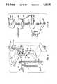
- FIG. 1is an elevational perspective exterior view of the apparatus of this invention
- FIG. 2is an elevational perspective interior view of the upper section of the apparatus of this invention showing the turret assembly partly exposed, and one sample storage chute pivoted to its horizontal loading position;
- FIG. 3is an exploded perspective view of the turret assembly
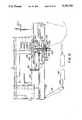
- FIG. 4is an exploded perspective view of the control panel of the apparatus of this invention and the handle-operated turret activating mechanism and timer associated with said panel;
- FIG. 5is an exploded, perspective view of the lower interior of the apparatus of this invention showing the cam assembly and the cable mechanism used to rotate the cams;
- FIG. 6is an enlarged exploded, perspective view of the cam assembly and its associated cable wheel mechanism
- FIG. 7is an exploded, perspective view of the trap door activation mechanism, the cam assembly and their associated elements
- FIG. 8is a front elevational, perspective view showing the turret assembly and the reciprocating rams used to push the sample onto the trap door located beneath the turret table;
- FIGS. 9A, 9B, 9C and 9Dare schematic sectional top views of the turret illustrating a cycle during rotation of the turret in the sample dispensing operation of the apparatus of this invention and showing the operation of the two reciprocating rams;
- FIGS. 10A, 10B, 10C and 10Dare top plan views illustrating the different cam effects during activation of the cam and dispensing of the sample;
- FIGS. 11A, 11B, 11C and 11Dare side plan views illustrating the timer mechanism used in the apparatus of this invention for time delay between dispensing successive samples
- FIG. 12is a side cross sectional view of a portion of the turret drive mechanism and the rams used to eject the package samples, and
- FIG. 13is a perspective view of the turret driving mechanism illustrating the operation of the rams.
- the apparatus of this inventionis in the general form of an upstanding housing designated as 10 and comprises a front swing door 11 which swings open as shown in FIG. 2.
- the apparatus of this inventionmay be 5 ft. high, 20 inches wide and 2 ft. deep although the exact dimensions are not per se critical. It comprises an upper section comprising a turret assembly and a lower section comprising a cam assembly and its associated cable mechanism, as hereinafter described.
- the apparatuswill be described for dispensing free samples of small 3 ⁇ 3 inch packages which may contain cookies, crackers, medicinal or other products which are generally packaged in such small packages.
- the swing door 11has a generally rectangular opening 13 for access to a control panel 12 on which is mounted an operating handle 15, whose function will be described hereinafter. Visible through the opening 13 above the handle 15 is an elongated coupon dispensing slot 17 and a coupon push button 19 which, in the coupon dispensing mode, (when the apparatus is empty of sample packages) can be pushed to dispense redemption coupons through the slot 17.
- a conventional coupon dispensing machinemay be employed.
- buttons A, B and Care also shown on the swing door 11, above the rectangular opening 13, are three electronically lighted push buttons A, B and C.
- push button AWhen push button A is illuminated, the apparatus is in the package dispensing mode. Illumination of push button B indicates that the machine is in the loading mode and illumination of push button C indicates that the apparatus is empty.
- push button 19When the apparatus is empty, push button 19 may be activated to dispense redeemable coupons.
- the push buttons A, B, and Care installed within the electronic circuit 21 as shown in FIG. 2.
- the coupon dispensing mechanismconstitutes an optional feature of the apparatus of this invention and its inclusion is not necessary.
- the swing door 11contains an access opening 23 for the removal of each sample that is dispensed into the sample receiving chute or compartment 24.
- the opening 23may state "Take free sample here."
- a slot 25 in the swing door 11is for waste so that users may insert empty packages into the lower housing compartment after their contents have been removed.
- FIGS. 2 and 3show the turret assembly 27 comprising a plurality of vertical sample-containing chutes 29 circumferentially arranged, preferably equidistantly, about the turret base plate 31.
- the turret assembly 27has 12 chutes, with each chute being sized to normally store 33 vertically loaded sample packages.
- FIG. 2illustrates one chute 29 opened to its full horizontal position, with the chute being nested within the elongated chute receiving channel 33, in order to load the chute 29 with the sample packages.
- Each chute 29is provided with a plurality of vertical slots 35 to observe the level to which the chute is packed with the packages, and has a bottom opening through which the package may drop freely.
- the turret support plate 31is fixed to the lower turret wheel 37.
- the turret support plate 31 and the lower turret wheel 37are aligned and secured to one another by a plurality of threaded screws 41, or by some other suitable means.
- the shaft 105extends through the turret base plate 31 and the turret wheel 37 and is secured (e.g. by welding) to a primary crankshaft 210 which has a primary orbiting shaft 211 secured thereto and spaced apart from the shaft 105.
- the driving wheel 212engages a right side slot (not shown) on the turret support plate 31, and as the shaft turns 180 degrees it will advance the turret until said slot assumes the position of the next adjacent slot (see also FIGS. 9A-9D and FIG. 12). The turret now will have rotated 30 degrees clockwise.
- cross link generally peanut shaped member 249secured (e.g. welded) at one end to the top of the primary orbiting shaft 211, and the other end is secured to the secondary orbiting shaft 215 which engages the driving wheel 213.
- member 249will be described in more detail in connection with description of FIG. 12.
- a sample containment channel 43which is U shaped in cross-section is positioned behind each of the chutes 29.
- the sample containment channel 43serves as the back wall of the chute 29 when the chute 29 is in its normal vertical position. Also the channel 43 spaces the support plate 31 from the turret top plate 53.
- each pair of adjacent chutes 29is rigidly secured by an intermediate vertical structural channel 45 by means of the threaded screws 47.
- each of the chutes 29has a central recess 49 adapted to releasably engage one end of the spring clip 51 which snaps into the recess.
- the other (horizontal) end of the clip 51is affixed to the top surface of the turret top plate 53 by means of the rivets 55.
- the clips 51are arranged circumferentially about the turret top plate 53 as shown in FIG. 3 so as to snap into the respective recesses of the sample-containing chutes 29.
- the chuteBy simply pushing the end of the clip 51 upward with the thumb, the chute is freed to pivot downward and drop to a horizontal position, as shown in FIG. 2.
- the chute 29may be lowered by service personnel when it needs to be refilled with a fresh supply of sample packages.
- the chute receiving channel 33is pivoted to the turret base plate 31 by means of an L-shaped brackets 57 and is held at about horizontal position, when released, by a link chain (not shown).
- a turret central plate 57is affixed (e.g., tab locked) to the chutes as shown in FIG. 3 in order to provide increased mechanical integrity to the turret assembly.
- FIG. 4the pulley or sear plate 59 which is coupled to and is activated by the operating handle 15 through the central shaft 61 which also extends through the cam 63.
- a cable 65extends from the circumferential groove 67 of the pulley 59 and over the cable spool 69 (see also FIG. 5) in the lower housing of the dispensing apparatus as will hereinafter be described.
- both the pulley 59 and the cam 63will be turned by the central shaft 61 causing the adjacent pivot weight plate 71 to fall as it is no longer held upward by the cam 63.
- the pivot weight plate 71rotates on the support bracket 79.
- a roller 81is held by means of pivotable bracket 83 against the pulley 59 by the spring 85 between the weight plate 71 and the pivotable bracket 83. After the operating handle 15 is pushed down to its lowermost position, the roller 81 engages the recessed surface 59a of the pulley 59 and holds the handle 15 in that position for a predetermined time, usually about 30 seconds. When the weight plate 71 returns to its previous down position, it disengages the roller 81 off the plate 59 and allows the handle 15 to return to its initial position. Ordinarily this weight plate 71 has a tendency to immediately drop back to its initial position, thus reversing the direction of rotation of the cam 63 and the plate 59 and raising the operating handle 15 to its initial position.
- the pivot weight plate 71is attached by means of the L-shaped bracket 73 to the air pot 75 which has a central reciprocating shaft 77.
- the shaft 77is secured at its lower end to the L-shaped bracket 73.
- the air pot 75is bolted to the control panel 12 by the L-shaped bracket 75b. Air pot 75 serves to retard the pivot weight plate 71 from returning to its initial position until a predetermined time, usually 25-30 seconds, has elapsed.
- the weight plate 71is secured to a timer by pass plate member 74 by the pivot pin 76 such that when the plate member 74 is pushed to the right, the pivotable bracket 83 will be prevented from engaging the recessed surface 59a of the pulley 59. Therefore when the operating handle 15 is pulled down and the plate member 74 is pushed to the right, the operating handle 15 will return quickly to its initial position without time delay.
- the time by pass mechanismallows quick loading and unloading of the chutes when desired.
- the cable 65 from the pulley 59extends down through the turret support table 87, then partly around an adjustable idler pulley 89 and the cable spool 69, extending to and terminating at 91 where the cable 65 is looped around the bolt 92 of the pivot rocker arm 93.
- Rocker arm 93pivots on a pin 94 in the support stanchion 97.
- the rocker arm 93is pivotly secured to shaft 250 (see FIG. 12) of cylinder 95 which is held within the support stanchion 97 and is fixed at its top end by bolting it to support table 87.
- the stanchion 97may be additionally secured to the lower interior walls of the apparatus by means of side bars or braces (not shown).
- the tension on the cable 65may be adjusted by removal of pin 96 from a pair of slots 98 of the support stanchion and placing it into an alternative pair of slots (only one slot of the pair being visible in FIG. 5).
- a hydraulic damping devicewhich is adjustable to vary the return speed of shaft 250.
- the cable spool 69is ratchetted to a pair of cams, i.e., an upper cam 101 and a lower cam 103, and may rotate and slide on shaft 105.
- the cams 101 and 103have central aligned openings through which extends the central shaft 105 and are fixed to the shaft 105 which is free to rotate in the bracket 107 and the turret support table 87.
- the cams 101, 103also rotate with the shaft 105 by the ratchet mechanism between the spool 69 and cam 103.
- the ratchetengages every 180 degrees to rotate the cams and shafts clockwise, while the spool 69 may oscillate clockwise to turn the cams and counterclockwise to engage the next tooth of the ratchet.
- the bracket 107has an L-shaped portion 109 which is secured to the turret support 87 as at 111 (see FIG. 7).
- the turret support table 87also serves to partition the upper chamber from the lower chamber of the apparatus.
- the coil spring 131is retained at one end to the plate 133 and at the other end to the bracket member 135.
- the bracket member 135is bolted to the turret table 87.
- a return coil spring 132is connected at one end to turret table 87 and is connected at its opposite end to door 115 to normally urge the door 115 in a clockwise (open) direction.
- the pivotable trap door 115having one arm 116 pivotally attached to the turret table by means of the pivot bolt 117, and a swing arm 119 which is operative to swing back and forth.
- the arm 119opens and closes the opening 121 in the turret support table 87, through which opening the sample packages drop into the sample receiving chute 24 for removal by the user (see FIGS. 2 and 8).
- a side chutemay lead from the side to opening 121, which permits the sample to be ejected onto the trap door arm 119 instead of directly through the opening 121.
- the trap door 115is attached to one end of a heavy coil spring 125, the other end of the coil spring 125 being connected to the pivotable trap door closer levers 143 and 141 by means of a nut and bolt 143b.
- the spring wire link 129has one end secured to the arm 116 of the swing door 115 and the other end hooked onto the plate 133.
- the wire link 129serves to pull the positive stop plates 127, 128 with the cam follower roller 139 away from the step in portion 103b of cam 103 whenever the trap door 115 is open. This allows the vend cycle to begin.
- FIG. 7Also shown in FIG. 7 are the pair of cams 101 and 103 with their respective cam follower rollers 137 and 139.
- the pair of levers 141 and 143 and the positive stop plates 127, 128rotatably mount the cam rollers 137 and 139, respectively.
- the cam roller 137is rotatably mounted in one end between the levers 141, 143 whereas the cam roller 139 is rotatably mounted between the positive stop plates 127, 128.
- the pivoting points of each of the levers 141 and 143, and the positive stop plates 127, 128are rotatably mounted on the stationery pin 145 which is fixed on the turret plate 87.
- the levers 141, 143will rotate freely clockwise when the cam 101 is rotated in response to the activation of the door handle 15 and the cam roller 137 rides up the lobe of cam 101 connecting spring 125 thereby closing the trap door 115.
- Cam 103rotates as well and the step in portion 103b moves past stop roller 139 before trap door 115 has closed, and spring 131 causes the positive plates 127 and 128 to rotate counterclockwise so roller 139 will ride down the lobe of cam 103 until the roller contacts the face of step in 103b thereby stopping all rotation of the cams 101, 103, respectively, and ceasing further rotation of the turret.
- roller 137drops off step in cam 101b and spring 132 opens trap door 115. The system will then return to the initial cycle.
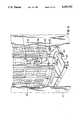
- FIG. 8a sample package is shown at the point of ejection from the bottom opening in the sample containing chute 29, the chute being shown partly in cutaway section to illustrate the lower oscillating sample ejector ram 147 and the upper oscillating sample ejector ram 149.
- the rams 147, 149are interconnected by means of linkage on shaft 105 which is illustrated in FIG. 13 and which allows the rams 147, 149 to reciprocate freely as the shaft 105 pivots.
- the linkage rollers 213 and 212cause the turret to advance approximately 30 degrees as the rams rotate 180 degrees.
- FIGS. 9-13The apparatus of this invention and its operation will now be described with particular reference to FIGS. 9-13. Although the operation and the use of the apparatus will be described for the best mode now contemplated, it must be understood that this description is not intended to limit the scope of the invention, but rather it is illustrative of the apparatus and its operation. Also, for the sake of illustration, the apparatus and its operation will be described in connection with dispensing sample packages, or simply samples of packaged products for use or try out by consumers.
- FIG. 9Aillustrates the beginning of a vend (dispensing) cycle showing the turret with only the last ten samples not yet vended in order to illustrate the mechanism of the operation more clearly.
- twelve sample-containing chutes 29are circumferentially arranged about the turret base plate 31, with each chute 29 typically containing 33 vertically stacked 3 ⁇ 3 samples. Each sample is held in position by the inner containment channel 151 and each chute 29 is open at the bottom. The opening is sufficiently large to allow only the lowermost sample to escape to the outside of the turret.
- the turret support table 87has an opening 121.
- Each inner containment channel 151extends from the top of the turret base plate 31 to a point slightly above the oscillating rams 147, 149, but slightly below the upper surface of the sample in order to prevent the sample from falling inside the turret, while allowing free movement of the rams below them.
- the next sample that will be dispensedis pushed by the lower oscillating ram 147 off the turret base plate 31 by said lower oscillating ram 147 out and over a staging ramp 153 which is located underneath the turret base plate 31.
- the sample indicator wire 155pivots in counterclockwise direction.
- the trap door opening 121(see FIG. 8) is open (see FIGS. 10A through 10D), the upper oscillating ram 147 is pulled slightly out from under the sample which was adjacently above the sample which was immediately dispensed.
- the turretis prevented from rotating by the turret advancing rollers 212 and 213 (see FIG. 9A) which are located under the oscillating rams as both rollers are engaged in the turret slots simultaneously.
- FIG. 9Bshows the driver mechanism advanced 58 degrees clockwise.
- the lower ram 147has pushed the sample almost off the turret base plate 31 as the sample drops to the staging ramp and the adjacently above sample begins to drop onto said ram 147.
- the upper ram 149is now fully escaped from the chute.
- the lower ram roller entering the turret table slotshas now rotated the turret 8.4 degrees clockwise and the trap door 115 has closed (see FIGS. 10A-10D).
- the samplehas also rotated with the turret and therefore it is partly off the staging ramp but not yet dropped from the staging ramp to the opening 121 below the ramp.
- the driver mechanismhas rotated approximately 106 degrees clockwise and the sample is pushed and dropped off the turret by the ram 147 which is extended beyond the edge of the turret base plate 31.
- the samplehas been pushed off of the staging ramp 153 and through the opening 121 of the turret plate 31 and rests on the trap door 115.
- the next samplehas dropped on top of the lower ram 147 as the upper ram 149 approaches the next sample, with the turret having turned approximately 18.4 degrees clockwise by this stage.
- the sample indicator wire 155is pivoted clockwise by an internal spring (not shown) and is caught by the next sample. If the mechanism is empty, however, the sample indicator wire 155 will rotate further and close the micro-switch 64 in order to illuminate the "empty" display.
- the driver mechanismhas been rotated a full 180 degrees with the turret having rotated 30 degrees clockwise.
- Trap door 115opens, the sample thus falls into the sample receptacle 123 wherefrom it may be retrieved by the customer.
- the relative positions of the ramsare now reversed by reciprocating motions about their common central control bushings and the cycle can be repeated upon pulling down the operating handle which has, by now, returned to its initial position.
- FIGS. 9A-9Ddescribe the different steps of operation at various degrees of rotation, in actual operation, upon pulling down the operating handle 15, the entire operation proceeds in a smooth continuous cycle.
- the turret wheel 37is both supported and permitted to rotate by rollers (not shown) circumferentially mounted underneath the turret wheel.
- FIGS. 10A-10DThe operation of the cams 101 and 103 and their associated mechanisms to open and close the trap door 115 is illustrated in FIGS. 10A-10D.
- the trap door 115is fully open by the action of the light coil return spring 132.
- the door closer lever 143is fully rotated in a counterclockwise direction about the stationery pivot 145 and the roller 137 rests against the valley portion of the cam 101.
- the positive stop lever 128 and the insulated roller 139are held away from the cam 103 by the spring wire link 129 (see FIG. 7).
- Heavy spring 125is at static length and is not extended. This spring may be considered a solid link since it will only extend if an obstruction prevents the swinging trap door 115 from closing fully thereby jamming the mechanism.
- FIG. 10Bthe shafts and the cams have rotated 58 degrees clockwise.
- the roller 137is now at the highest point of the cam 101 and will remain at this position until the end of the cycle when, once again, it drops to its lowest position as shown in FIG. 10A.
- the spring 125 and the door closer lever 141, 143move clockwise and pulls down the trap door 115 about the stationery pivot 117 to fully close the door before the sample is pushed from the turret into the opening 121 (see FIG. 8).
- the light spring 132is now in an extended position.
- FIG. 10Cthe cams have rotated 180 degrees clockwise.
- the roller 139has followed the contour of cam 103 to its lowest point by the action of the hairpin spring 129 and thus interrupts rotation of the cams immediately after the roller 137 has dropped off the high point of the cam 101 as shown in FIG. 10D, which shows the cams 101, 103 and their respective shafts rotating at 180 degrees, and the door closer lever 143 returned to its original position in FIG. 10A as the trap door 115 is opened by the light spring 132 and the sample thus drops into the sample receptacle chute 24 where it can be retrieved by the customer.
- one novel feature of the sample dispenser of this inventionis that it includes a time--delay mechanism so that a predetermined time of about say 25-30 seconds lapses after vending each sample before the next sample can be dispensed.
- time delay mechanismsare generally known, one such system for use in the present apparatus is illustrated in FIGS. 11A to 11D and will now be described.
- FIG. 11Aillustrates the relative positions of the operating handle 15, the pulley 59, the cam 63, the weight plate 71, the air pot 75, the link wire 74 and the timer roller 81 before a customer pushes down the operating handle 15.
- handle 15As handle 15 is pushed down in a clockwise direction (see FIG. 11B), it will rotate the cam 63 and the plate 59 in the clockwise direction and the timer roller 81 will assume the position shown in FIG. 11B against the face 59a of plate 59. Clockwise rotation of the plate 59 causes the cable 65 to be pulled in the clockwise direction.
- the weight plate 71has been separated from and is no longer in contact with the cam 63 and the microswitch 64 is operated by pin 63a on the cam 63.
- FIG. 11Billustrates the timer off-on lever 74. In the timer off position roller 81 is held away from the pulley 59 so the handle 15 may return immediately for quicker loading of the turret.
- the rotatable shaft 105(driver shaft) is shown mounted rotatably within the support bushing 200.
- the cam 103has protruding 180 degrees ratchet teeth 202 on its upper face which mesh with the protruding driving 180 degrees ratchet teeth 203 in the bottom face of the cable spool 69.
- Thisforms a one-way ratchet clutch mechanism so that clockwise motion (as seen from the top) of the cable spool 69 rotates the cam 103, but the counterclockwise motion of the cable spool 69 does not move the cam 103.
- the cable spool 69slides over the cam 103 during its counterclockwise rotation.
- the cams 101 and 103are fixed to the driver shaft 105.
- the cable spool 69is not fixed to this shaft but rather, is freely mounted rotatably thereon.
- a coil spring 201is held between the top of the cable spool 69 and the bottom of the cam 101 and urges the cable spool 69 downwardly against the cam 103.
- the ram 149is connected to the driver shaft 105 via arm 210, shaft 211 cross link 249 and pivot 215 so that the rotary movement of the driver shaft pivots the ram clockwise a given angle.
- the orbiting shaft 211drives the lower ram 147.
- a pin 150connects the lower ram 147 and the upper ram 149 and drives the lower ram 147.
- the turretis rotated by the rollers 212 and 213 which are inserted, in sequence, one after the other, in successive elongated slots 214 of the turret support plate 31 (see FIGS. 9A-9D).
- the ram, along with the inserted roller,is turned 180 degrees (for a 12 chute turret) while turning the turret support plate 30 degrees.
Landscapes
- Physics & Mathematics (AREA)
- General Physics & Mathematics (AREA)
- Vending Machines For Individual Products (AREA)
Abstract
Description
Claims (10)
Priority Applications (1)
| Application Number | Priority Date | Filing Date | Title |
|---|---|---|---|
| US07/886,037US5253782A (en) | 1992-05-20 | 1992-05-20 | Article dispensing apparatus |
Applications Claiming Priority (1)
| Application Number | Priority Date | Filing Date | Title |
|---|---|---|---|
| US07/886,037US5253782A (en) | 1992-05-20 | 1992-05-20 | Article dispensing apparatus |
Publications (1)
| Publication Number | Publication Date |
|---|---|
| US5253782Atrue US5253782A (en) | 1993-10-19 |
Family
ID=25388245
Family Applications (1)
| Application Number | Title | Priority Date | Filing Date |
|---|---|---|---|
| US07/886,037Expired - Fee RelatedUS5253782A (en) | 1992-05-20 | 1992-05-20 | Article dispensing apparatus |
Country Status (1)
| Country | Link |
|---|---|
| US (1) | US5253782A (en) |
Cited By (43)
| Publication number | Priority date | Publication date | Assignee | Title |
|---|---|---|---|---|
| US5472114A (en)* | 1994-07-11 | 1995-12-05 | Riverwood International Corporation | Turret magazine assembly |
| DE4420805A1 (en)* | 1994-06-16 | 1995-12-21 | P & P Materialflussysteme Gmbh | Storing and delivery system for articles esp. in chemist shop |
| US20040245278A1 (en)* | 2003-01-30 | 2004-12-09 | Steffens Lowell G. | Propane tank vending machine |
| US20050082308A1 (en)* | 2003-10-16 | 2005-04-21 | Simson Anton K. | Machine for controlled dispensing of small articles |
| US7207330B1 (en) | 1999-06-05 | 2007-04-24 | Innovata Biomed Limited | Delivery system |
| US7219665B1 (en)* | 1999-09-04 | 2007-05-22 | Innovata Biomed Limited | Delivery device |
| USD545373S1 (en) | 2004-01-30 | 2007-06-26 | Avalon Returnable Packaging, Inc | Propane tank vending machine assembly |
| US20070170201A1 (en)* | 2003-01-30 | 2007-07-26 | Steffens Lowell G | Propane tank vending machine assembly |
| US20070187423A1 (en)* | 2006-02-10 | 2007-08-16 | Cerner Innovation, Inc. | Apparatus for dispensing medications |
| US20070187424A1 (en)* | 2006-02-10 | 2007-08-16 | Cerner Innovation, Inc. | Method for dispensing medications |
| US20080201013A1 (en)* | 2005-08-03 | 2008-08-21 | Gerhard Schaefer | Device for Contactless Detection of Filling Levels |
| US7464704B2 (en) | 2001-11-23 | 2008-12-16 | Innovata Biomed Limited | Medicament delivery assembly |
| US20090242582A1 (en)* | 2003-10-17 | 2009-10-01 | Rock-Tenn Shared Services, Llc | Theft deterrent system |
| US20090284157A1 (en)* | 2006-01-09 | 2009-11-19 | Whirlpool Corporation | Control for a refrigerator door dispenser light |
| US20100193538A1 (en)* | 2007-06-18 | 2010-08-05 | Stephen William Clarke | Dispensing device |
| US20100294803A1 (en)* | 2008-03-28 | 2010-11-25 | Sedat Tetikli | Machine for the supply of the toothpaste by way of spreading the same on a toothbrush |
| US20120116578A1 (en)* | 2010-11-08 | 2012-05-10 | Junfang Zhang | Sales kiosk |
| US8225458B1 (en) | 2001-07-13 | 2012-07-24 | Hoffberg Steven M | Intelligent door restraint |
| US8353425B2 (en) | 2005-04-25 | 2013-01-15 | Rock-Tenn Shared Services, Llc | Time delay product pushing system |
| US8386075B2 (en) | 2003-10-17 | 2013-02-26 | Rock-Tenn Shared Services, Llc | Dispensing and display system |
| US8511302B2 (en) | 2004-04-24 | 2013-08-20 | Innovata Biomed Limited | Dose counter mechanisms for medicament delivery devices |
| US8646650B2 (en) | 2010-05-19 | 2014-02-11 | Rock-Tenn Shared Services, Llc | Product dispensing system |
| WO2014080088A1 (en) | 2012-11-23 | 2014-05-30 | Gip Finland Oy | Device and method for storing and dispensing articles |
| US8851069B2 (en) | 2004-04-21 | 2014-10-07 | Innovata Biomed Limited | Inhaler |
| US8910827B2 (en) | 2011-05-10 | 2014-12-16 | Rock-Tenn Shared Services, Llc | Secure merchandising display with tunnel feature |
| US8984644B2 (en) | 2003-07-01 | 2015-03-17 | Securityprofiling, Llc | Anti-vulnerability system, method, and computer program product |
| US9100431B2 (en) | 2003-07-01 | 2015-08-04 | Securityprofiling, Llc | Computer program product and apparatus for multi-path remediation |
| US9118708B2 (en) | 2003-07-01 | 2015-08-25 | Securityprofiling, Llc | Multi-path remediation |
| US9118709B2 (en) | 2003-07-01 | 2015-08-25 | Securityprofiling, Llc | Anti-vulnerability system, method, and computer program product |
| US9118711B2 (en) | 2003-07-01 | 2015-08-25 | Securityprofiling, Llc | Anti-vulnerability system, method, and computer program product |
| US9118710B2 (en) | 2003-07-01 | 2015-08-25 | Securityprofiling, Llc | System, method, and computer program product for reporting an occurrence in different manners |
| US9117069B2 (en) | 2003-07-01 | 2015-08-25 | Securityprofiling, Llc | Real-time vulnerability monitoring |
| US9119488B2 (en) | 2009-09-25 | 2015-09-01 | Rock-Tenn Shared Services, Llc | Secure merchandising display with blocker mechanisms |
| US9289078B2 (en) | 2004-02-03 | 2016-03-22 | Rtc Industries, Inc. | Product securement and management system |
| US9350752B2 (en) | 2003-07-01 | 2016-05-24 | Securityprofiling, Llc | Anti-vulnerability system, method, and computer program product |
| US9375100B2 (en) | 2004-02-03 | 2016-06-28 | Rtc Industries, Inc. | Product securement and management system |
| US9706857B2 (en) | 2004-02-03 | 2017-07-18 | Rtc Industries, Inc. | Product securement and management system |
| US10217310B2 (en)* | 2017-04-21 | 2019-02-26 | Noodle Time Holdings Limited | Vending machine |
| US20210043024A1 (en)* | 2018-02-02 | 2021-02-11 | Jukka, Inc. | Assembly for product support and deployment for a vending machine |
| EP3879503A1 (en)* | 2020-03-11 | 2021-09-15 | Becton Dickinson Rowa Germany GmbH | Storage and discharge station for medicines |
| US20210284430A1 (en)* | 2020-03-11 | 2021-09-16 | Becton Dickinson Rowa Germany Gmbh | Storage and dispensing station for drugs |
| US11375826B2 (en) | 2004-02-03 | 2022-07-05 | Rtc Industries, Inc. | Product securement and management system |
| US11763622B2 (en) | 2019-03-21 | 2023-09-19 | Xinsuo Group Co., Ltd. | Vending machine for vending luggage |
Citations (11)
| Publication number | Priority date | Publication date | Assignee | Title |
|---|---|---|---|---|
| US844431A (en)* | 1906-08-09 | 1907-02-19 | Didrich H Wehagen | Delivery-cabinet. |
| US1044591A (en)* | 1911-12-16 | 1912-11-19 | Theodore Stocker | Vending apparatus. |
| US1777269A (en)* | 1928-03-17 | 1930-09-30 | Polar Vend Corp | Distributing machine |
| US2338335A (en)* | 1941-08-19 | 1944-01-04 | King Julius | Vending machine |
| US2777604A (en)* | 1953-11-13 | 1957-01-15 | Welch Grant | Shell dispenser |
| US3162287A (en)* | 1963-05-29 | 1964-12-22 | Lupovici David | Vending machine |
| US3179289A (en)* | 1963-04-09 | 1965-04-20 | Moyer & Diebel Metalcrafts Ltd | Article dispenser with selection from plural rotatable stacks |
| US3722739A (en)* | 1970-03-23 | 1973-03-27 | M Blumberg | Pill dispenser having clockwork for periodic dispensing |
| US4872591A (en)* | 1987-11-19 | 1989-10-10 | Konopka Richard O | Medication dispenser |
| US5127544A (en)* | 1990-04-13 | 1992-07-07 | Design Technology Corporation | Method and apparatus for handling buns and meat patties |
| US5152422A (en)* | 1990-12-17 | 1992-10-06 | Springer Reinhold A | Medication dispenser |
- 1992
- 1992-05-20USUS07/886,037patent/US5253782A/ennot_activeExpired - Fee Related
Patent Citations (11)
| Publication number | Priority date | Publication date | Assignee | Title |
|---|---|---|---|---|
| US844431A (en)* | 1906-08-09 | 1907-02-19 | Didrich H Wehagen | Delivery-cabinet. |
| US1044591A (en)* | 1911-12-16 | 1912-11-19 | Theodore Stocker | Vending apparatus. |
| US1777269A (en)* | 1928-03-17 | 1930-09-30 | Polar Vend Corp | Distributing machine |
| US2338335A (en)* | 1941-08-19 | 1944-01-04 | King Julius | Vending machine |
| US2777604A (en)* | 1953-11-13 | 1957-01-15 | Welch Grant | Shell dispenser |
| US3179289A (en)* | 1963-04-09 | 1965-04-20 | Moyer & Diebel Metalcrafts Ltd | Article dispenser with selection from plural rotatable stacks |
| US3162287A (en)* | 1963-05-29 | 1964-12-22 | Lupovici David | Vending machine |
| US3722739A (en)* | 1970-03-23 | 1973-03-27 | M Blumberg | Pill dispenser having clockwork for periodic dispensing |
| US4872591A (en)* | 1987-11-19 | 1989-10-10 | Konopka Richard O | Medication dispenser |
| US5127544A (en)* | 1990-04-13 | 1992-07-07 | Design Technology Corporation | Method and apparatus for handling buns and meat patties |
| US5152422A (en)* | 1990-12-17 | 1992-10-06 | Springer Reinhold A | Medication dispenser |
Cited By (80)
| Publication number | Priority date | Publication date | Assignee | Title |
|---|---|---|---|---|
| DE4420805A1 (en)* | 1994-06-16 | 1995-12-21 | P & P Materialflussysteme Gmbh | Storing and delivery system for articles esp. in chemist shop |
| WO1996002045A1 (en)* | 1994-07-11 | 1996-01-25 | Riverwood International Corporation | Turret magazine assembly |
| US5472114A (en)* | 1994-07-11 | 1995-12-05 | Riverwood International Corporation | Turret magazine assembly |
| US7207330B1 (en) | 1999-06-05 | 2007-04-24 | Innovata Biomed Limited | Delivery system |
| US7571723B2 (en) | 1999-09-04 | 2009-08-11 | Innovata Biomed Limited | Delivery device |
| US7571724B2 (en) | 1999-09-04 | 2009-08-11 | Innovata Biomed Limited | Delivery device |
| US8205614B2 (en) | 1999-09-04 | 2012-06-26 | Innovata Biomed Limited | Delivery device |
| US7219665B1 (en)* | 1999-09-04 | 2007-05-22 | Innovata Biomed Limited | Delivery device |
| US8225458B1 (en) | 2001-07-13 | 2012-07-24 | Hoffberg Steven M | Intelligent door restraint |
| US9995076B1 (en) | 2001-07-13 | 2018-06-12 | Steven M. Hoffberg | Intelligent door restraint |
| US9121217B1 (en) | 2001-07-13 | 2015-09-01 | Steven M. Hoffberg | Intelligent door restraint |
| US9045927B1 (en) | 2001-07-13 | 2015-06-02 | Steven M. Hoffberg | Intelligent door restraint |
| US11187022B1 (en) | 2001-07-13 | 2021-11-30 | Steven M. Hoffberg | Intelligent door restraint |
| US7464704B2 (en) | 2001-11-23 | 2008-12-16 | Innovata Biomed Limited | Medicament delivery assembly |
| US8800550B2 (en) | 2001-11-23 | 2014-08-12 | Innovata Biomed Limited | Medicament delivery assembly |
| US20070170201A1 (en)* | 2003-01-30 | 2007-07-26 | Steffens Lowell G | Propane tank vending machine assembly |
| US20040245278A1 (en)* | 2003-01-30 | 2004-12-09 | Steffens Lowell G. | Propane tank vending machine |
| US10050988B2 (en) | 2003-07-01 | 2018-08-14 | Securityprofiling, Llc | Computer program product and apparatus for multi-path remediation |
| US8984644B2 (en) | 2003-07-01 | 2015-03-17 | Securityprofiling, Llc | Anti-vulnerability system, method, and computer program product |
| US9118710B2 (en) | 2003-07-01 | 2015-08-25 | Securityprofiling, Llc | System, method, and computer program product for reporting an occurrence in different manners |
| US10154055B2 (en) | 2003-07-01 | 2018-12-11 | Securityprofiling, Llc | Real-time vulnerability monitoring |
| US10104110B2 (en) | 2003-07-01 | 2018-10-16 | Securityprofiling, Llc | Anti-vulnerability system, method, and computer program product |
| US9100431B2 (en) | 2003-07-01 | 2015-08-04 | Securityprofiling, Llc | Computer program product and apparatus for multi-path remediation |
| US10021124B2 (en) | 2003-07-01 | 2018-07-10 | Securityprofiling, Llc | Computer program product and apparatus for multi-path remediation |
| US9118711B2 (en) | 2003-07-01 | 2015-08-25 | Securityprofiling, Llc | Anti-vulnerability system, method, and computer program product |
| US9350752B2 (en) | 2003-07-01 | 2016-05-24 | Securityprofiling, Llc | Anti-vulnerability system, method, and computer program product |
| US9118708B2 (en) | 2003-07-01 | 2015-08-25 | Securityprofiling, Llc | Multi-path remediation |
| US9118709B2 (en) | 2003-07-01 | 2015-08-25 | Securityprofiling, Llc | Anti-vulnerability system, method, and computer program product |
| US9225686B2 (en) | 2003-07-01 | 2015-12-29 | Securityprofiling, Llc | Anti-vulnerability system, method, and computer program product |
| US9117069B2 (en) | 2003-07-01 | 2015-08-25 | Securityprofiling, Llc | Real-time vulnerability monitoring |
| US20050082308A1 (en)* | 2003-10-16 | 2005-04-21 | Simson Anton K. | Machine for controlled dispensing of small articles |
| US8386075B2 (en) | 2003-10-17 | 2013-02-26 | Rock-Tenn Shared Services, Llc | Dispensing and display system |
| US20090242582A1 (en)* | 2003-10-17 | 2009-10-01 | Rock-Tenn Shared Services, Llc | Theft deterrent system |
| US8485391B2 (en)* | 2003-10-17 | 2013-07-16 | Rock-Tenn Shared Services, Llc | Theft deterrent system |
| US9052994B2 (en) | 2003-10-17 | 2015-06-09 | Rock-Tenn Shared Services, Llc | Dispensing and display system |
| US9483896B2 (en) | 2003-10-17 | 2016-11-01 | Westrock Shared Services, Llc | Dispensing and display system |
| USD545373S1 (en) | 2004-01-30 | 2007-06-26 | Avalon Returnable Packaging, Inc | Propane tank vending machine assembly |
| US9289078B2 (en) | 2004-02-03 | 2016-03-22 | Rtc Industries, Inc. | Product securement and management system |
| US10667630B2 (en) | 2004-02-03 | 2020-06-02 | Rtc Industries, Inc. | Product securement and management system |
| US11659943B2 (en) | 2004-02-03 | 2023-05-30 | Rtc Industries, Inc. | Product securement and management system |
| US11375826B2 (en) | 2004-02-03 | 2022-07-05 | Rtc Industries, Inc. | Product securement and management system |
| US11058234B2 (en) | 2004-02-03 | 2021-07-13 | Rtc Industries, Inc. | Product securement and management system |
| US10945538B2 (en) | 2004-02-03 | 2021-03-16 | Rtc Industries, Inc. | Product securement and management system |
| US10349755B2 (en) | 2004-02-03 | 2019-07-16 | Rtc Industries, Inc. | Product securement and management system |
| US10258169B2 (en) | 2004-02-03 | 2019-04-16 | Rtc Industries, Inc. | Product securement and management system |
| US10051977B2 (en) | 2004-02-03 | 2018-08-21 | Rtc Industries, Inc. | Product securement and management system |
| US9993091B2 (en) | 2004-02-03 | 2018-06-12 | Rtc Industries, Inc. | Product securement and management system |
| US9844280B2 (en) | 2004-02-03 | 2017-12-19 | Rtc Industries, Inc. | Product securement and management system |
| US9723934B2 (en) | 2004-02-03 | 2017-08-08 | Rtc Industries, Inc. | Product securement and management system |
| US9375100B2 (en) | 2004-02-03 | 2016-06-28 | Rtc Industries, Inc. | Product securement and management system |
| US9706857B2 (en) | 2004-02-03 | 2017-07-18 | Rtc Industries, Inc. | Product securement and management system |
| US9526351B2 (en) | 2004-02-03 | 2016-12-27 | Rtc Industries, Inc. | Product securement and management system |
| US9687085B2 (en)* | 2004-02-03 | 2017-06-27 | Rtc Industries, Inc. | Product securement and management system |
| US8851069B2 (en) | 2004-04-21 | 2014-10-07 | Innovata Biomed Limited | Inhaler |
| US8511302B2 (en) | 2004-04-24 | 2013-08-20 | Innovata Biomed Limited | Dose counter mechanisms for medicament delivery devices |
| US8353425B2 (en) | 2005-04-25 | 2013-01-15 | Rock-Tenn Shared Services, Llc | Time delay product pushing system |
| US20080201013A1 (en)* | 2005-08-03 | 2008-08-21 | Gerhard Schaefer | Device for Contactless Detection of Filling Levels |
| US20090284157A1 (en)* | 2006-01-09 | 2009-11-19 | Whirlpool Corporation | Control for a refrigerator door dispenser light |
| US7921658B2 (en)* | 2006-01-09 | 2011-04-12 | Whirlpool Corporation | Control for a refrigerator door dispenser light |
| US7673771B2 (en)* | 2006-02-10 | 2010-03-09 | Cerner Innovation, Inc. | Apparatus for dispensing medications |
| US7673772B2 (en)* | 2006-02-10 | 2010-03-09 | Cerner Innovation, Inc. | Method for dispensing medications |
| US20070187424A1 (en)* | 2006-02-10 | 2007-08-16 | Cerner Innovation, Inc. | Method for dispensing medications |
| US20070187423A1 (en)* | 2006-02-10 | 2007-08-16 | Cerner Innovation, Inc. | Apparatus for dispensing medications |
| US20100193538A1 (en)* | 2007-06-18 | 2010-08-05 | Stephen William Clarke | Dispensing device |
| US10555622B2 (en)* | 2007-06-18 | 2020-02-11 | Stephen William Clarke | Dispensing device |
| US20100294803A1 (en)* | 2008-03-28 | 2010-11-25 | Sedat Tetikli | Machine for the supply of the toothpaste by way of spreading the same on a toothbrush |
| US9119488B2 (en) | 2009-09-25 | 2015-09-01 | Rock-Tenn Shared Services, Llc | Secure merchandising display with blocker mechanisms |
| US8646650B2 (en) | 2010-05-19 | 2014-02-11 | Rock-Tenn Shared Services, Llc | Product dispensing system |
| US8720742B2 (en)* | 2010-11-08 | 2014-05-13 | Junfang Zhang | Sales kiosk |
| US20120116578A1 (en)* | 2010-11-08 | 2012-05-10 | Junfang Zhang | Sales kiosk |
| US8910827B2 (en) | 2011-05-10 | 2014-12-16 | Rock-Tenn Shared Services, Llc | Secure merchandising display with tunnel feature |
| US9603467B2 (en) | 2011-05-10 | 2017-03-28 | Westrock Shared Services, Llc | Secure merchandising display with tunnel feature |
| WO2014080088A1 (en) | 2012-11-23 | 2014-05-30 | Gip Finland Oy | Device and method for storing and dispensing articles |
| US10217310B2 (en)* | 2017-04-21 | 2019-02-26 | Noodle Time Holdings Limited | Vending machine |
| US20210043024A1 (en)* | 2018-02-02 | 2021-02-11 | Jukka, Inc. | Assembly for product support and deployment for a vending machine |
| US12154406B2 (en)* | 2018-02-02 | 2024-11-26 | Automated Retail Technologies. LLC | Assembly for product support and deployment for a vending machine |
| US11763622B2 (en) | 2019-03-21 | 2023-09-19 | Xinsuo Group Co., Ltd. | Vending machine for vending luggage |
| US20210284430A1 (en)* | 2020-03-11 | 2021-09-16 | Becton Dickinson Rowa Germany Gmbh | Storage and dispensing station for drugs |
| US11577905B2 (en)* | 2020-03-11 | 2023-02-14 | Becton Dickinson Rowa Germany Gmbh | Storage and dispensing station for drugs |
| EP3879503A1 (en)* | 2020-03-11 | 2021-09-15 | Becton Dickinson Rowa Germany GmbH | Storage and discharge station for medicines |
Similar Documents
| Publication | Publication Date | Title |
|---|---|---|
| US5253782A (en) | Article dispensing apparatus | |
| US5167345A (en) | Dual dispenser | |
| US4542834A (en) | Dispensing mechanism for vending machines | |
| US5199598A (en) | Dispensing apparatus for tennis ball containers | |
| KR910001095B1 (en) | Vending Basket | |
| US3737071A (en) | Product dispensing apparatus | |
| US4632274A (en) | Beverage dispenser | |
| US4359935A (en) | Apparatus for cooking and dispensing food | |
| US4574980A (en) | Vending machine dispensing mechanism | |
| US4591070A (en) | Article dispenser adjustable for different size articles | |
| US5038969A (en) | Lid dispenser | |
| KR20020054350A (en) | Centralized vending method using cartridge-loaded machines | |
| US3712507A (en) | Article dispensing apparatus and methods | |
| US4312461A (en) | Newspaper vending machine | |
| CA1211417A (en) | Dispensing mechanism for vending machines or the like | |
| US4369896A (en) | Helical vending machine with pivot panel adjustment | |
| JPS6013230B2 (en) | Goods vending machine | |
| GB2344679A (en) | Rotary arcade game | |
| US3904076A (en) | Adaptable dispensing apparatus with unique escrow bar and associated latch mechanism | |
| EP1008116B1 (en) | Coin dispensing apparatus | |
| CA2197421C (en) | Co-dispensing snack food products and beverages from a vending machine | |
| US2888165A (en) | Package vending machine | |
| US3424345A (en) | Cradle mechanism | |
| US4454961A (en) | Package dispensing mechanism for vending machine | |
| AU2005202193A1 (en) | System for removing the selected product in automatic vending machines |
Legal Events
| Date | Code | Title | Description |
|---|---|---|---|
| AS | Assignment | Owner name:WIEBEL, PAUL A.S., NEW JERSEY Free format text:ASSIGNMENT OF ASSIGNORS INTEREST.;ASSIGNORS:GATES, LAWRENCE B.;CRAWLEY, CHARLES P.;REEL/FRAME:006166/0694;SIGNING DATES FROM 19920527 TO 19920608 | |
| AS | Assignment | Owner name:F.O. PHOENIX, INC., NEW JERSEY Free format text:ASSIGNMENT OF ASSIGNORS INTEREST;ASSIGNOR:WIEBEL, PAUL A.S.;REEL/FRAME:008133/0493 Effective date:19960524 | |
| REMI | Maintenance fee reminder mailed | ||
| FPAY | Fee payment | Year of fee payment:4 | |
| SULP | Surcharge for late payment | ||
| AS | Assignment | Owner name:NATIONSBANK, N.A., AS AGENT, NORTH CAROLINA Free format text:SECURITY AGREEMENT;ASSIGNOR:F.O. PHOENIX, INC.;REEL/FRAME:010033/0408 Effective date:19990331 | |
| AS | Assignment | Owner name:BANK OF AMERICA, N.A. AS AGENT, ILLINOIS Free format text:SECURITY AGREEMENT;ASSIGNOR:P.O.P. DISPLAYS;REEL/FRAME:010795/0630 Effective date:20000404 | |
| AS | Assignment | Owner name:BANK OF AMERICA, N.A. AS AGENT, ILLINOIS Free format text:SECURITY INTEREST;ASSIGNOR:F.O. PHOENIX, INC.;REEL/FRAME:010795/0571 Effective date:20000404 | |
| REMI | Maintenance fee reminder mailed | ||
| LAPS | Lapse for failure to pay maintenance fees | ||
| STCH | Information on status: patent discontinuation | Free format text:PATENT EXPIRED DUE TO NONPAYMENT OF MAINTENANCE FEES UNDER 37 CFR 1.362 | |
| FP | Lapsed due to failure to pay maintenance fee | Effective date:20011019 | |
| AS | Assignment | Owner name:FOOTHILL CAPITAL CORPORATION, CALIFORNIA Free format text:SECURITY INTEREST;ASSIGNOR:F.O. PHOENIX, INC., A NEW JERSEY CORPORATION;REEL/FRAME:013645/0456 Effective date:20021022 |