US5253260A - Apparatus and method for passive heat pipe cooling of solid state laser heads - Google Patents
Apparatus and method for passive heat pipe cooling of solid state laser headsDownload PDFInfo
- Publication number
- US5253260A US5253260AUS07/812,505US81250591AUS5253260AUS 5253260 AUS5253260 AUS 5253260AUS 81250591 AUS81250591 AUS 81250591AUS 5253260 AUS5253260 AUS 5253260A
- Authority
- US
- United States
- Prior art keywords
- heat
- heat pipe
- laser
- solid state
- state laser
- Prior art date
- Legal status (The legal status is an assumption and is not a legal conclusion. Google has not performed a legal analysis and makes no representation as to the accuracy of the status listed.)
- Expired - Lifetime
Links
- 239000007787solidSubstances0.000titleclaimsabstractdescription23
- 238000001816coolingMethods0.000titleclaimsdescription31
- 238000000034methodMethods0.000titleclaimsdescription6
- 238000005086pumpingMethods0.000claimsabstractdescription36
- 230000000712assemblyEffects0.000claimsabstractdescription21
- 238000000429assemblyMethods0.000claimsabstractdescription21
- 238000003491arrayMethods0.000claimsabstractdescription12
- 230000007480spreadingEffects0.000claimsabstractdescription4
- 238000005338heat storageMethods0.000claimsdescription17
- 239000012782phase change materialSubstances0.000claimsdescription8
- 239000004020conductorSubstances0.000claimsdescription3
- 230000008878couplingEffects0.000claims6
- 238000010168coupling processMethods0.000claims6
- 238000005859coupling reactionMethods0.000claims6
- 229920001971elastomerPolymers0.000description6
- 239000000806elastomerSubstances0.000description6
- 230000008901benefitEffects0.000description5
- 238000010276constructionMethods0.000description3
- 229910052594sapphireInorganic materials0.000description3
- 239000010980sapphireSubstances0.000description3
- 229910052782aluminiumInorganic materials0.000description2
- XAGFODPZIPBFFR-UHFFFAOYSA-NaluminiumChemical compound[Al]XAGFODPZIPBFFR-UHFFFAOYSA-N0.000description2
- 238000010438heat treatmentMethods0.000description2
- 239000007788liquidSubstances0.000description2
- 230000007246mechanismEffects0.000description2
- 229910052751metalInorganic materials0.000description2
- 239000002184metalSubstances0.000description2
- 239000012808vapor phaseSubstances0.000description2
- RYGMFSIKBFXOCR-UHFFFAOYSA-NCopperChemical compound[Cu]RYGMFSIKBFXOCR-UHFFFAOYSA-N0.000description1
- 230000009471actionEffects0.000description1
- 230000002411adverseEffects0.000description1
- 230000005540biological transmissionEffects0.000description1
- 239000003990capacitorSubstances0.000description1
- 230000001427coherent effectEffects0.000description1
- 229910052802copperInorganic materials0.000description1
- 239000010949copperSubstances0.000description1
- 230000001419dependent effectEffects0.000description1
- 239000013536elastomeric materialSubstances0.000description1
- 238000005516engineering processMethods0.000description1
- YVVOLRMUSPYVJE-UHFFFAOYSA-Glithium;neodymium(3+);yttrium(3+);heptafluorideChemical compound[Li+].[F-].[F-].[F-].[F-].[F-].[F-].[F-].[Y+3].[Nd+3]YVVOLRMUSPYVJE-UHFFFAOYSA-G0.000description1
- 238000012986modificationMethods0.000description1
- 230000004048modificationEffects0.000description1
- 238000005057refrigerationMethods0.000description1
- 239000000565sealantSubstances0.000description1
- 230000004936stimulating effectEffects0.000description1
Images


Classifications
- H—ELECTRICITY
- H01—ELECTRIC ELEMENTS
- H01S—DEVICES USING THE PROCESS OF LIGHT AMPLIFICATION BY STIMULATED EMISSION OF RADIATION [LASER] TO AMPLIFY OR GENERATE LIGHT; DEVICES USING STIMULATED EMISSION OF ELECTROMAGNETIC RADIATION IN WAVE RANGES OTHER THAN OPTICAL
- H01S3/00—Lasers, i.e. devices using stimulated emission of electromagnetic radiation in the infrared, visible or ultraviolet wave range
- H01S3/02—Constructional details
- H01S3/04—Arrangements for thermal management
- H01S3/042—Arrangements for thermal management for solid state lasers
- F—MECHANICAL ENGINEERING; LIGHTING; HEATING; WEAPONS; BLASTING
- F28—HEAT EXCHANGE IN GENERAL
- F28D—HEAT-EXCHANGE APPARATUS, NOT PROVIDED FOR IN ANOTHER SUBCLASS, IN WHICH THE HEAT-EXCHANGE MEDIA DO NOT COME INTO DIRECT CONTACT
- F28D15/00—Heat-exchange apparatus with the intermediate heat-transfer medium in closed tubes passing into or through the conduit walls ; Heat-exchange apparatus employing intermediate heat-transfer medium or bodies
- F28D15/02—Heat-exchange apparatus with the intermediate heat-transfer medium in closed tubes passing into or through the conduit walls ; Heat-exchange apparatus employing intermediate heat-transfer medium or bodies in which the medium condenses and evaporates, e.g. heat pipes
- F28D15/0275—Arrangements for coupling heat-pipes together or with other structures, e.g. with base blocks; Heat pipe cores
- F—MECHANICAL ENGINEERING; LIGHTING; HEATING; WEAPONS; BLASTING
- F28—HEAT EXCHANGE IN GENERAL
- F28D—HEAT-EXCHANGE APPARATUS, NOT PROVIDED FOR IN ANOTHER SUBCLASS, IN WHICH THE HEAT-EXCHANGE MEDIA DO NOT COME INTO DIRECT CONTACT
- F28D15/00—Heat-exchange apparatus with the intermediate heat-transfer medium in closed tubes passing into or through the conduit walls ; Heat-exchange apparatus employing intermediate heat-transfer medium or bodies
- F28D15/02—Heat-exchange apparatus with the intermediate heat-transfer medium in closed tubes passing into or through the conduit walls ; Heat-exchange apparatus employing intermediate heat-transfer medium or bodies in which the medium condenses and evaporates, e.g. heat pipes
- F28D15/06—Control arrangements therefor
- H—ELECTRICITY
- H01—ELECTRIC ELEMENTS
- H01S—DEVICES USING THE PROCESS OF LIGHT AMPLIFICATION BY STIMULATED EMISSION OF RADIATION [LASER] TO AMPLIFY OR GENERATE LIGHT; DEVICES USING STIMULATED EMISSION OF ELECTROMAGNETIC RADIATION IN WAVE RANGES OTHER THAN OPTICAL
- H01S3/00—Lasers, i.e. devices using stimulated emission of electromagnetic radiation in the infrared, visible or ultraviolet wave range
- H01S3/02—Constructional details
- H01S3/04—Arrangements for thermal management
- H01S3/0405—Conductive cooling, e.g. by heat sinks or thermo-electric elements
- H—ELECTRICITY
- H01—ELECTRIC ELEMENTS
- H01S—DEVICES USING THE PROCESS OF LIGHT AMPLIFICATION BY STIMULATED EMISSION OF RADIATION [LASER] TO AMPLIFY OR GENERATE LIGHT; DEVICES USING STIMULATED EMISSION OF ELECTROMAGNETIC RADIATION IN WAVE RANGES OTHER THAN OPTICAL
- H01S3/00—Lasers, i.e. devices using stimulated emission of electromagnetic radiation in the infrared, visible or ultraviolet wave range
- H01S3/09—Processes or apparatus for excitation, e.g. pumping
- H01S3/091—Processes or apparatus for excitation, e.g. pumping using optical pumping
- H01S3/094—Processes or apparatus for excitation, e.g. pumping using optical pumping by coherent light
- H01S3/0941—Processes or apparatus for excitation, e.g. pumping using optical pumping by coherent light of a laser diode
- H—ELECTRICITY
- H01—ELECTRIC ELEMENTS
- H01S—DEVICES USING THE PROCESS OF LIGHT AMPLIFICATION BY STIMULATED EMISSION OF RADIATION [LASER] TO AMPLIFY OR GENERATE LIGHT; DEVICES USING STIMULATED EMISSION OF ELECTROMAGNETIC RADIATION IN WAVE RANGES OTHER THAN OPTICAL
- H01S5/00—Semiconductor lasers
- H01S5/02—Structural details or components not essential to laser action
- H01S5/024—Arrangements for thermal management
- H01S5/02469—Passive cooling, e.g. where heat is removed by the housing as a whole or by a heat pipe without any active cooling element like a TEC
- H—ELECTRICITY
- H01—ELECTRIC ELEMENTS
- H01S—DEVICES USING THE PROCESS OF LIGHT AMPLIFICATION BY STIMULATED EMISSION OF RADIATION [LASER] TO AMPLIFY OR GENERATE LIGHT; DEVICES USING STIMULATED EMISSION OF ELECTROMAGNETIC RADIATION IN WAVE RANGES OTHER THAN OPTICAL
- H01S5/00—Semiconductor lasers
- H01S5/40—Arrangement of two or more semiconductor lasers, not provided for in groups H01S5/02 - H01S5/30
- H01S5/4025—Array arrangements, e.g. constituted by discrete laser diodes or laser bar
Definitions
- the present inventionrelates to cooling of solid state lasers and, more particularly, to passive cooling of such lasers by fixed and/or variable conductance heat pipes.
- the removal of heat, generated in the course of stimulating coherent emission from a laser devicecan be effected through the use of any one of many conventional active and passive cooling methods and implementations, and is dependent upon the specific type of laser to be cooled and the environment in which it is to be used.
- the present inventionis directed specifically to solid state lasers which are pumped by such pumping means as laser amplifier diodes and flash lamps. Because the preferred pumping implementation comprises laser diodes used in combination with a solid state laser, the following discussion will be specifically directed to this combination. However, it is to be understood that the present invention is not intended to be limited to this specific combination, but to a combination of a solid state laser and pumping means therefor.
- thermal management systemsinclude liquid cooling, conduction cooling (e.g., by a metal strap), heat pump cooling (e.g., by a thermoelectric cooler), vapor phase refrigeration, and heat pipe cooling.
- liquid coolingconduction cooling (e.g., by a metal strap)
- heat pump coolinge.g., by a thermoelectric cooler
- vapor phase refrigeratione.g., by a thermoelectric cooler
- liquid coolingcan provide a low incremental temperature, it is complex, has moving parts, consumes power, is susceptible to clogging and, therefore, is unreliable, and requires active temperature control.
- the major attractions of the conductive cooling techniqueis its simplicity, as not having any moving parts, and its reliability. However, it is heavy and thus unsuitable such as for use in air or space borne vehicles. It cannot be readily packaged in different configurations, and is limited to conduction from fixed points. Auxiliary heating and cooling control is required.
- the heat pump or thermoelectric cooleris compact and lightweight, but consumes power and requires active temperature control.
- the major advantage of the vapor phase refrigeratoris its ability to handle large differential temperatures. However, it is heavy, large and inefficient. Its reliability is questionable, as being subject to leaks. Like all of the above techniques, active temperature control is required.
- the present inventionrecognizes the advantages and disadvantages of the above-described mechanisms, and improves upon them.
- a solid state laser assemblywhich includes the combination of a laser pumping device positioned adjacent to a laser rod, is maintained at an operating temperature by at least one heat pipe thermally coupled to both the pumping device and the laser rod assembly for removing heat therefrom.
- the laser assemblyincludes a pump cavity configured as an I-beam having two pairs of terminal faces respectively bounding a pair of elongated U-shaped channels.
- the preferred pumping meanscomprises a plurality of laser diode arrays which comprise diode bars and which are assembled into two groups. The diode array groups are placed on opposed sides of the laser rod.
- a pair of heat pipe assembliesare physically and thermally secured at their evaporator sections respectively both to the mounting block of the diode array assemblies and to the pairs of terminal interfaces.
- Each diode array mounting blockphysically and thermally supports each diode array assembly for spreading heat therefrom to its evaporator section. Heat is thus removed from the laser rod through the pump cavity to the heat pipe assemblies, and from the diodes also to the heat pipe assemblies.
- Both the solid state laser rod and its pumping mediumare passively cooled, while the pumping medium is maintained at its optimum operating temperature. Because passive cooling requires no power therefor, the overall efficiency of the system is improved. No moving parts are needed. Adjustment to changes in external temperatures over even a broad range is automatic.
- the heat pipe designis relatively simple, and thereby enhances system reliability and efficiency.
- FIG. 1is a perspective view of the present invention embodied as a passively cooled solid state laser head utilizing a heat pipe cooling arrangement, which may include, if desired, a space radiator;
- FIG. 2is an exploded and enlarged perspective view of the laser head and the evaporative end of the heat pipe assembly depicted in FIG. 1;
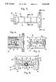
- FIG. 3is a top view of the pump cavity housing portion of the laser head shown in FIG. 2;
- FIG. 4is a cross-sectional view of the pump cavity housing taken along line 4-4 of FIG. 3;
- FIG. 5is a cross-sectional view of the pump cavity housing taken along line 5-5 of FIG. 3;
- FIG. 6is view, partially in cross-section and partially cut away, of the laser head depicted in FIG. 2;
- FIG. 7is cross-section of the laser head taken along line 7--7 of FIG. 6;
- FIG. 8is a view of a portion of the laser head and heat pipe cooling arrangement therefor illustrating the heat flow from both the laser rod assembly and its pumping diode arrays.
- FIG. 1illustrates an assemblage 10 of a passively cooled solid state laser head 12 and a heat pipe cooling arrangement therefor generally denoted by indicium 14.
- Heat pipe cooling arrangement 14includes at least one heat pipe cooling mechanism defined, preferably, as a pair of heat pipe assemblies 16.
- laser head 12includes a laser rod 36 and a pumping medium, such as an array 60 of laser diode bars 62 (shown in FIG. 7) or a flash lamp.
- a pumping mediumsuch as an array 60 of laser diode bars 62 (shown in FIG. 7) or a flash lamp.
- the output wavelength of the pumping mediummust be controlled within a specified range; otherwise, the pumping efficiency will be adversely affected.
- Heat pipe assemblies 16are of conventional design and each may comprise a fixed or a variable conductance type having evaporator and condenser portions 18 and 20 coupled together by an adiabatic portion 22. Each heat pipe assembly 16 is thermally coupled to laser head 12 at its evaporator portion 18 in order that heat, which is generated by the laser head, can be transferred through its condenser portion 20 to a heat sink.
- the thermal connection to the heat sinkmay be direct or indirect, depending upon the environment in which the present invention is to be used.
- heat pipe cooling arrangement 14 and the heat sink connectionhave the following preferable construction.
- Assemblies 16utilize fixed conductance heat pipes.
- the heat sink connectioncomprises the use of a heat storage device 24 thermally coupled at one side 26 to condenser sections 20 of heat pipe assemblies 16 and at its other side 28 to a space radiator 30 through a variable conductance heat pipe 32.
- Heat storage device 24includes a phase change material (PCM).
- PCMphase change material
- heat pipe assembliesembodied as fixed conductance heat pipes, connect laser head 12 and any associated electronics and, if desired, other heat generating components to heat storage device 24, which thereby acts as a dedicated heat capacitor.
- Variable conductance heat pipe 32is then used to connect storage device 24 to space radiator 30 or other suitable heat sink.
- This arrangementlimits the temperature variation at laser head 12 and, most importantly, its laser diode bars 62 for reasons given below, to a variation of a few degrees-while the ambient temperature at radiator 30 can vary over a wide range, e.g., from the heat of the sun to the cold of space.
- diode arrays 60be operated at a junction temperature, e.g., of 70° C., which is defined as the actual temperature at the emitting diode surface. It is this temperature which controls the output wavelength of the diode array which, in turn, controls the laser pumping efficiency. Studies show that the diode temperature variation should be restricted to ⁇ 10° C. to limit the wavelength variation of the diode output to about 3 nanometer. Accordingly, because the temperature of the diode junction must be controlled to within several degrees, the temperature of heat storage device 24 is also restricted to the same range. This result is accomplished by using a fixed capacitance heat pipe as each assembly 16 between laser head 12 and heat storage device 24. However, because the surface temperature of space radiator 30 may differ from that of heat storage device 24 over a period of time, variable conductance heat pipe 32 is used to maintain a relatively constant temperature of heat storage device 24 and, therefore, of the diode junction.
- a junction temperaturee.g., of 70° C.
- laser head 12includes a two piece laser pump cavity housing 34 which supports a laser rod 36, for example a Nd:YLF (neodymium-yttrium lithium fluoride) laser rod.
- Housing 34is formed from any suitable thermally conductive material, such as aluminum.
- Laser rod 36is supported in housing 34 in any suitable manner, such as by the arrangement disclosed in U.S. Pat. No. 4,637,028, and which is also shown in FIGS. 6 and 7.
- the FIG. 6 and 7 supporting arrangementdepicts a sapphire tube or sleeve 38, an elastomer 40 between sleeve 38 and rod 36, and another elastomer 42 between sleeve 38 and housing 34.
- the laser rodis encased in sapphire tube 38 and is supported therein by elastomer 40, which comprises a suitable thermally conductive, transparent elastomeric material and which fills a small gap between rod 36 and sleeve 38.
- a sealantis used as an end seal for sleeve 38.
- the elastomerboth structurally supports the laser rod and eliminates stress induced bifringence due to thermal expansion of the rod, and additionally maintains thermal contact between the rod and the sapphire sleeve for efficient heat transfer from the rod to the sleeve.
- Elastomer 42comprises a suitable thermally conductive material, for example, an aluminum filled elastomer, to ensure that heat generated in laser rod 36 will be conducted to pump housing 34.
- two piece housing 34includes a central portion 44 having an I-beam configuration closed and supported by ends 46.
- the I-beam configurationdefines a pair of opposed, outwardly facing U-shaped channels 48 which open at their centers.
- the two piece construction of housing 34forms two T-shaped structures whose legs 50 extend towards each other from cross-bars 52 and terminate in curved surfaces 54 that are spaced from one another. Curved surfaces 54 not only thus form a cylindrically shaped opening, which defines the cavity for laser rod 36, but also side openings 56 extending into U-shaped channels 48.
- Cross-bars 52terminate in surfaces 58, to- which evaporator sections 18 of heat pipe assemblies 16 are structurally and thermally secured.
- each U-shaped channel 48there are a group of array assemblies.
- the array assembliescomprise an array 60 of laser diode bars 62 mounted on a mounting block 64, for example of copper, which acts also as a heat spreader. Each assembly is structurally and thermally secured to its associated evaporator section 18.
- Laser diode arrays 60are positioned adjacent openings 56 so that the light from the laser diode bars will cause a laser pumping action in laser rod 36.
- Laser diode bars 62 of arrays 60may comprise any conventional construction, provided that, as arrays, they provide sufficient energy to obtain stimulated emission in the laser rod.
- Diode arrays 60may be replaced with a flash lamp, provided also that it produces sufficient pumping energy.
- laser head 12is configured to provide a two-sided pumping. However, if desired or needed, greater or lesser pumping may be provided. As an example of further or additional pumping, another pair of diode array groups may be positioned 90° with respect to the first pair about laser rod 36. If space does not permit, the second pair may be axially, as well as normally, displaced about the laser rod with respect to the first pair. Accordingly, depending upon the laser pumping needs, laser head can be configured to provide one sided pumping or multiple sided pumping.
- Operation of the present inventionmay be understood with reference to FIG. 8.
- Energization of arrays 60 of the laser diode barspumps light into laser rod 36, causing it to produce stimulated emission.
- the temperatures of both the laser diode bars and the laser rodincrease. Heat is conducted from rod 36 into legs 50 of pump housing 34 and thence through the four surfaces 58 of cross-bars 52 into evaporator sections 18 of heat pipe assemblies 16. Heat from diode arrays 60 is conducted into heat spreader mounting block 64 and thence also into evaporator sections 18.
Landscapes
- Engineering & Computer Science (AREA)
- Physics & Mathematics (AREA)
- Electromagnetism (AREA)
- Life Sciences & Earth Sciences (AREA)
- Sustainable Development (AREA)
- Thermal Sciences (AREA)
- Mechanical Engineering (AREA)
- General Engineering & Computer Science (AREA)
- Plasma & Fusion (AREA)
- Optics & Photonics (AREA)
- Lasers (AREA)
Abstract
Description
Claims (15)
Priority Applications (1)
| Application Number | Priority Date | Filing Date | Title |
|---|---|---|---|
| US07/812,505US5253260A (en) | 1991-12-20 | 1991-12-20 | Apparatus and method for passive heat pipe cooling of solid state laser heads |
Applications Claiming Priority (1)
| Application Number | Priority Date | Filing Date | Title |
|---|---|---|---|
| US07/812,505US5253260A (en) | 1991-12-20 | 1991-12-20 | Apparatus and method for passive heat pipe cooling of solid state laser heads |
Publications (1)
| Publication Number | Publication Date |
|---|---|
| US5253260Atrue US5253260A (en) | 1993-10-12 |
Family
ID=25209783
Family Applications (1)
| Application Number | Title | Priority Date | Filing Date |
|---|---|---|---|
| US07/812,505Expired - LifetimeUS5253260A (en) | 1991-12-20 | 1991-12-20 | Apparatus and method for passive heat pipe cooling of solid state laser heads |
Country Status (1)
| Country | Link |
|---|---|
| US (1) | US5253260A (en) |
Cited By (51)
| Publication number | Priority date | Publication date | Assignee | Title |
|---|---|---|---|---|
| US5315609A (en)* | 1991-10-30 | 1994-05-24 | Hitachi, Ltd. | Semiconductor laser module with lens holder compensating for thermal stress |
| US5475702A (en)* | 1994-05-31 | 1995-12-12 | General Electric Company | Diode pumped slab module |
| US5504764A (en)* | 1994-11-30 | 1996-04-02 | The United States Of America As Represented By The Secretary Of The Army | Micro-heatpipe cooling of solid-state slab |
| US5802087A (en)* | 1995-01-11 | 1998-09-01 | Miyachi Technos Corporation | Laser apparatus |
| GB2329758A (en)* | 1997-09-26 | 1999-03-31 | Marconi Gec Ltd | A semiconductor laser diode bar assembly |
| US5892783A (en)* | 1997-05-19 | 1999-04-06 | Spectra Physics Lasers, Inc. | Laser with temperature controller positioned in laser head |
| US5963574A (en)* | 1995-10-11 | 1999-10-05 | Raytheon Company | Compact diode pumped solid state laser |
| US5982792A (en)* | 1997-04-21 | 1999-11-09 | Nec Corporation | Solid-state laser device |
| US5991317A (en)* | 1994-02-04 | 1999-11-23 | Spectra Physics Lasers, Inc. | Retinal photocoagulator including diode pumped, multi-axial mode intracavity doubled laser |
| US6026109A (en)* | 1998-01-22 | 2000-02-15 | Cutting Edge Optronics, Inc. | High-power, solid-state laser in a cylindrical package |
| WO2000028671A3 (en)* | 1998-06-10 | 2001-01-04 | Lsa Inc | Laser communication system and methods |
| EP0987799A3 (en)* | 1998-09-11 | 2001-01-10 | Cutting Edge Optronics, Inc. | Laser system using phase change material for thermal control |
| US6240116B1 (en) | 1997-08-14 | 2001-05-29 | Sdl, Inc. | Laser diode array assemblies with optimized brightness conservation |
| US6351478B1 (en)* | 1998-09-11 | 2002-02-26 | Cutting Edge Optronics, Inc. | Passively cooled solid-state laser |
| US6352873B1 (en)* | 1997-10-14 | 2002-03-05 | Decade Products, Inc. | Method for modular laser diode assembly |
| EP1241752A3 (en)* | 2001-03-16 | 2004-04-07 | The Furukawa Electric Co., Ltd. | Light source having plural laser diode modules |
| US20040114657A1 (en)* | 2001-01-22 | 2004-06-17 | Jan Vetrovec | Side-pumped solid-state disk for high-average power |
| US6768751B2 (en) | 2002-06-17 | 2004-07-27 | The Boeing Company | Methods and apparatus for removing heat from a lasing medium of a solid-state laser assembly |
| US20040226695A1 (en)* | 2003-04-28 | 2004-11-18 | Bolle Cristian A. | Temperature control of thermooptic devices |
| US20050058173A1 (en)* | 2001-01-22 | 2005-03-17 | Jan Vetrovec | Side-pumped solid-state disk laser for high-average power |
| US20050158687A1 (en)* | 2002-07-25 | 2005-07-21 | Dahm Jonathan S. | Method and apparatus for using light emitting diodes for curing |
| US20050254013A1 (en)* | 2004-05-11 | 2005-11-17 | Engle T S | Projection LED cooling |
| US20060203866A1 (en)* | 2005-03-10 | 2006-09-14 | Northrop Grumman | Laser diode package with an internal fluid cooling channel |
| US7170919B2 (en) | 2003-06-23 | 2007-01-30 | Northrop Grumman Corporation | Diode-pumped solid-state laser gain module |
| US20070258493A1 (en)* | 2006-05-02 | 2007-11-08 | Northrop Grumman Corporation | Laser power reduction without mode change |
| US20080025357A1 (en)* | 2006-07-26 | 2008-01-31 | Northrop Grumman Corporation | Microchannel cooler for high efficiency laser diode heat extraction |
| US20080056314A1 (en)* | 2006-08-31 | 2008-03-06 | Northrop Grumman Corporation | High-power laser-diode package system |
| US7345320B2 (en) | 2002-08-23 | 2008-03-18 | Dahm Jonathan S | Light emitting apparatus |
| US7495848B2 (en) | 2003-07-24 | 2009-02-24 | Northrop Grumman Corporation | Cast laser optical bench |
| US20090049845A1 (en)* | 2007-05-30 | 2009-02-26 | Mcstravick David | Medical travel pack with cooling system |
| US7540634B2 (en) | 2004-06-15 | 2009-06-02 | Henkel Corporation | High power LED electro-optic assembly |
| US20090185593A1 (en)* | 2008-01-18 | 2009-07-23 | Northrop Grumman Space & Mission Systems Corp. | Method of manufacturing laser diode packages and arrays |
| US7586958B2 (en) | 2006-09-29 | 2009-09-08 | Northrop Grumman Corporation | Electro-opto switching of unpolarized lasers |
| US7645056B1 (en) | 1997-09-25 | 2010-01-12 | Koninklijke Philips Electronics N V | Optical irradiation device having LED and heat pipe |
| US8047686B2 (en) | 2006-09-01 | 2011-11-01 | Dahm Jonathan S | Multiple light-emitting element heat pipe assembly |
| US8345720B2 (en) | 2009-07-28 | 2013-01-01 | Northrop Grumman Systems Corp. | Laser diode ceramic cooler having circuitry for control and feedback of laser diode performance |
| US8937976B2 (en) | 2012-08-15 | 2015-01-20 | Northrop Grumman Systems Corp. | Tunable system for generating an optical pulse based on a double-pass semiconductor optical amplifier |
| US20170054265A1 (en)* | 2015-08-17 | 2017-02-23 | Hamilton Sundstrand Corporation | Thermal management systems |
| US9590388B2 (en) | 2011-01-11 | 2017-03-07 | Northrop Grumman Systems Corp. | Microchannel cooler for a single laser diode emitter based system |
| US20180023864A1 (en)* | 2014-12-15 | 2018-01-25 | Qingdao Haier Joint Stock Co., Ltd. | Bent pipe and semiconductor refrigeration refrigerator with bent pipe |
| US10158210B2 (en) | 2014-12-17 | 2018-12-18 | Nlight, Inc. | Optical loss management in high power diode laser packages |
| EP3589100A1 (en)* | 2018-06-29 | 2020-01-01 | Juniper Networks, Inc. | Thermal management with variable conductance heat pipe |
| CN112612137A (en)* | 2020-12-25 | 2021-04-06 | 江苏金海创科技有限公司 | Laser galvanometer with cooling structure |
| US11056854B2 (en) | 2018-08-14 | 2021-07-06 | Leonardo Electronics Us Inc. | Laser assembly and related methods |
| WO2022050071A1 (en)* | 2020-09-04 | 2022-03-10 | 浜松ホトニクス株式会社 | Laser device and method for manufacturing laser device |
| US11296481B2 (en) | 2019-01-09 | 2022-04-05 | Leonardo Electronics Us Inc. | Divergence reshaping array |
| US11406004B2 (en) | 2018-08-13 | 2022-08-02 | Leonardo Electronics Us Inc. | Use of metal-core printed circuit board (PCB) for generation of ultra-narrow, high-current pulse driver |
| US11705690B2 (en) | 2016-11-29 | 2023-07-18 | Leonardo Electronics Us Inc. | Dual junction fiber-coupled laser diode and related methods |
| US11752571B1 (en) | 2019-06-07 | 2023-09-12 | Leonardo Electronics Us Inc. | Coherent beam coupler |
| CN117773365A (en)* | 2024-02-23 | 2024-03-29 | 深圳欧斯普瑞智能科技有限公司 | Laser cutting head and cooling device thereof |
| US12253685B2 (en) | 2019-09-16 | 2025-03-18 | Leonardo Electronics Us Inc. | Asymmetric input intensity hexagonal homogenizer |
Citations (12)
| Publication number | Priority date | Publication date | Assignee | Title |
|---|---|---|---|---|
| US3619808A (en)* | 1970-07-06 | 1971-11-09 | Union Carbide Corp | Laser head cooling system |
| US3784929A (en)* | 1972-10-30 | 1974-01-08 | Rca Corp | Thermally-controlled crystalline lasers |
| US4003074A (en)* | 1973-12-03 | 1977-01-11 | Nippon Selfoc Co., Ltd. | Hermetically-sealed injection semiconductor laser device |
| US4232276A (en)* | 1977-10-11 | 1980-11-04 | Quanta-Ray, Inc. | Laser apparatus |
| US4637028A (en)* | 1984-08-02 | 1987-01-13 | Hughes Aircraft Company | Conductively cooled laser rod |
| US4673030A (en)* | 1980-10-20 | 1987-06-16 | Hughes Aircraft Company | Rechargeable thermal control system |
| US4791634A (en)* | 1987-09-29 | 1988-12-13 | Spectra-Physics, Inc. | Capillary heat pipe cooled diode pumped slab laser |
| US5031184A (en)* | 1989-07-01 | 1991-07-09 | Carl-Zeiss-Stiftung | Cooling arrangement for a semiconductor pump source |
| US5084886A (en)* | 1990-10-01 | 1992-01-28 | Laser Diode, Inc. | Side-pumped laser system with independent heat controls |
| US5105429A (en)* | 1990-07-06 | 1992-04-14 | The United States Of America As Represented By The Department Of Energy | Modular package for cooling a laser diode array |
| US5181214A (en)* | 1991-11-18 | 1993-01-19 | Harmonic Lightwaves, Inc. | Temperature stable solid-state laser package |
| US5195102A (en)* | 1991-09-13 | 1993-03-16 | Litton Systems Inc. | Temperature controlled laser diode package |
- 1991
- 1991-12-20USUS07/812,505patent/US5253260A/ennot_activeExpired - Lifetime
Patent Citations (12)
| Publication number | Priority date | Publication date | Assignee | Title |
|---|---|---|---|---|
| US3619808A (en)* | 1970-07-06 | 1971-11-09 | Union Carbide Corp | Laser head cooling system |
| US3784929A (en)* | 1972-10-30 | 1974-01-08 | Rca Corp | Thermally-controlled crystalline lasers |
| US4003074A (en)* | 1973-12-03 | 1977-01-11 | Nippon Selfoc Co., Ltd. | Hermetically-sealed injection semiconductor laser device |
| US4232276A (en)* | 1977-10-11 | 1980-11-04 | Quanta-Ray, Inc. | Laser apparatus |
| US4673030A (en)* | 1980-10-20 | 1987-06-16 | Hughes Aircraft Company | Rechargeable thermal control system |
| US4637028A (en)* | 1984-08-02 | 1987-01-13 | Hughes Aircraft Company | Conductively cooled laser rod |
| US4791634A (en)* | 1987-09-29 | 1988-12-13 | Spectra-Physics, Inc. | Capillary heat pipe cooled diode pumped slab laser |
| US5031184A (en)* | 1989-07-01 | 1991-07-09 | Carl-Zeiss-Stiftung | Cooling arrangement for a semiconductor pump source |
| US5105429A (en)* | 1990-07-06 | 1992-04-14 | The United States Of America As Represented By The Department Of Energy | Modular package for cooling a laser diode array |
| US5084886A (en)* | 1990-10-01 | 1992-01-28 | Laser Diode, Inc. | Side-pumped laser system with independent heat controls |
| US5195102A (en)* | 1991-09-13 | 1993-03-16 | Litton Systems Inc. | Temperature controlled laser diode package |
| US5181214A (en)* | 1991-11-18 | 1993-01-19 | Harmonic Lightwaves, Inc. | Temperature stable solid-state laser package |
Non-Patent Citations (2)
| Title |
|---|
| "Variable Conductance Heat Pipe Technology for Precise Temperature Control of the NASA/DDLT Transmitter" by D. E. Vanevenhoven and D. Antoniak, presented in SPIE vol. 1044 Optomechanical Design of Laser Transmitters and Receivers (1989), pp. 135-144. |
| Variable Conductance Heat Pipe Technology for Precise Temperature Control of the NASA/DDLT Transmitter by D. E. Vanevenhoven and D. Antoniak, presented in SPIE vol. 1044 Optomechanical Design of Laser Transmitters and Receivers (1989), pp. 135 144.* |
Cited By (81)
| Publication number | Priority date | Publication date | Assignee | Title |
|---|---|---|---|---|
| US5315609A (en)* | 1991-10-30 | 1994-05-24 | Hitachi, Ltd. | Semiconductor laser module with lens holder compensating for thermal stress |
| US5991317A (en)* | 1994-02-04 | 1999-11-23 | Spectra Physics Lasers, Inc. | Retinal photocoagulator including diode pumped, multi-axial mode intracavity doubled laser |
| US5475702A (en)* | 1994-05-31 | 1995-12-12 | General Electric Company | Diode pumped slab module |
| US5504764A (en)* | 1994-11-30 | 1996-04-02 | The United States Of America As Represented By The Secretary Of The Army | Micro-heatpipe cooling of solid-state slab |
| US5802087A (en)* | 1995-01-11 | 1998-09-01 | Miyachi Technos Corporation | Laser apparatus |
| US6241720B1 (en) | 1995-02-04 | 2001-06-05 | Spectra Physics, Inc. | Diode pumped, multi axial mode intracavity doubled laser |
| US5963574A (en)* | 1995-10-11 | 1999-10-05 | Raytheon Company | Compact diode pumped solid state laser |
| US5982792A (en)* | 1997-04-21 | 1999-11-09 | Nec Corporation | Solid-state laser device |
| US5892783A (en)* | 1997-05-19 | 1999-04-06 | Spectra Physics Lasers, Inc. | Laser with temperature controller positioned in laser head |
| US6240116B1 (en) | 1997-08-14 | 2001-05-29 | Sdl, Inc. | Laser diode array assemblies with optimized brightness conservation |
| US7645056B1 (en) | 1997-09-25 | 2010-01-12 | Koninklijke Philips Electronics N V | Optical irradiation device having LED and heat pipe |
| US8096691B2 (en) | 1997-09-25 | 2012-01-17 | Koninklijke Philips Electronics N V | Optical irradiation device |
| GB2329758B (en)* | 1997-09-26 | 1999-08-25 | Gec Marconi Avionics Holdings | A semiconductor laser diode bar assembly |
| WO1999017411A1 (en)* | 1997-09-26 | 1999-04-08 | Gec-Marconi Avionics (Holdings) Ltd | A semiconductor laser diode bar assembly |
| GB2329758A (en)* | 1997-09-26 | 1999-03-31 | Marconi Gec Ltd | A semiconductor laser diode bar assembly |
| US6352873B1 (en)* | 1997-10-14 | 2002-03-05 | Decade Products, Inc. | Method for modular laser diode assembly |
| US6026109A (en)* | 1998-01-22 | 2000-02-15 | Cutting Edge Optronics, Inc. | High-power, solid-state laser in a cylindrical package |
| US6285476B1 (en)* | 1998-06-10 | 2001-09-04 | Lsa, Inc. | Laser communication system and methods |
| WO2000028671A3 (en)* | 1998-06-10 | 2001-01-04 | Lsa Inc | Laser communication system and methods |
| US6307871B1 (en) | 1998-09-11 | 2001-10-23 | Cutting Edge Optronics, Inc. | Laser system using phase change material for thermal control |
| US6351478B1 (en)* | 1998-09-11 | 2002-02-26 | Cutting Edge Optronics, Inc. | Passively cooled solid-state laser |
| US6570895B2 (en)* | 1998-09-11 | 2003-05-27 | Cutting Edge Optronics, Inc. | Laser system using phase change material for thermal control |
| EP0987799A3 (en)* | 1998-09-11 | 2001-01-10 | Cutting Edge Optronics, Inc. | Laser system using phase change material for thermal control |
| US20040114657A1 (en)* | 2001-01-22 | 2004-06-17 | Jan Vetrovec | Side-pumped solid-state disk for high-average power |
| US20050058173A1 (en)* | 2001-01-22 | 2005-03-17 | Jan Vetrovec | Side-pumped solid-state disk laser for high-average power |
| US7200161B2 (en) | 2001-01-22 | 2007-04-03 | The Boeing Company | Side-pumped solid-state disk laser for high-average power |
| US6999839B2 (en) | 2001-01-22 | 2006-02-14 | The Boeing Company | Side-pumped solid-state disk for high-average power |
| EP1241752A3 (en)* | 2001-03-16 | 2004-04-07 | The Furukawa Electric Co., Ltd. | Light source having plural laser diode modules |
| US6768751B2 (en) | 2002-06-17 | 2004-07-27 | The Boeing Company | Methods and apparatus for removing heat from a lasing medium of a solid-state laser assembly |
| US9726435B2 (en) | 2002-07-25 | 2017-08-08 | Jonathan S. Dahm | Method and apparatus for using light emitting diodes for curing |
| US20050158687A1 (en)* | 2002-07-25 | 2005-07-21 | Dahm Jonathan S. | Method and apparatus for using light emitting diodes for curing |
| US7345320B2 (en) | 2002-08-23 | 2008-03-18 | Dahm Jonathan S | Light emitting apparatus |
| US7989839B2 (en) | 2002-08-23 | 2011-08-02 | Koninklijke Philips Electronics, N.V. | Method and apparatus for using light emitting diodes |
| US20100219736A1 (en)* | 2002-08-23 | 2010-09-02 | Dahm Jonathan S | Method and apparatus for using light emitting diodes |
| US7299859B2 (en)* | 2003-04-28 | 2007-11-27 | Lucent Technologies Inc. | Temperature control of thermooptic devices |
| US20040226695A1 (en)* | 2003-04-28 | 2004-11-18 | Bolle Cristian A. | Temperature control of thermooptic devices |
| US7170919B2 (en) | 2003-06-23 | 2007-01-30 | Northrop Grumman Corporation | Diode-pumped solid-state laser gain module |
| US7495848B2 (en) | 2003-07-24 | 2009-02-24 | Northrop Grumman Corporation | Cast laser optical bench |
| US7252385B2 (en)* | 2004-05-11 | 2007-08-07 | Infocus Corporation | Projection LED cooling |
| US20050254013A1 (en)* | 2004-05-11 | 2005-11-17 | Engle T S | Projection LED cooling |
| US20080007696A1 (en)* | 2004-05-11 | 2008-01-10 | Infocus Corporation | Projection led cooling |
| CN100592196C (en)* | 2004-05-11 | 2010-02-24 | 富可视公司 | Cooling of Projected LEDs |
| US7553028B2 (en) | 2004-05-11 | 2009-06-30 | Infocus Corporation | Projection LED cooling |
| US7540634B2 (en) | 2004-06-15 | 2009-06-02 | Henkel Corporation | High power LED electro-optic assembly |
| US7466732B2 (en) | 2005-03-10 | 2008-12-16 | Northrop Grumman Corporation | Laser diode package with an internal fluid cooling channel |
| US7305016B2 (en) | 2005-03-10 | 2007-12-04 | Northrop Grumman Corporation | Laser diode package with an internal fluid cooling channel |
| US20060203866A1 (en)* | 2005-03-10 | 2006-09-14 | Northrop Grumman | Laser diode package with an internal fluid cooling channel |
| US20070258493A1 (en)* | 2006-05-02 | 2007-11-08 | Northrop Grumman Corporation | Laser power reduction without mode change |
| US7460566B2 (en) | 2006-05-02 | 2008-12-02 | Northrop Grumman Corporation | Laser power reduction without mode change |
| US7957439B2 (en) | 2006-07-26 | 2011-06-07 | Northrop Grumman Space & Missions | Microchannel cooler for high efficiency laser diode heat extraction |
| US7656915B2 (en) | 2006-07-26 | 2010-02-02 | Northrop Grumman Space & Missions Systems Corp. | Microchannel cooler for high efficiency laser diode heat extraction |
| US20100074285A1 (en)* | 2006-07-26 | 2010-03-25 | Northrop Grumman Space & Mission Systems Corp. | Microchannel Cooler For High Efficiency Laser Diode Heat Extraction |
| US20080025357A1 (en)* | 2006-07-26 | 2008-01-31 | Northrop Grumman Corporation | Microchannel cooler for high efficiency laser diode heat extraction |
| US20080056314A1 (en)* | 2006-08-31 | 2008-03-06 | Northrop Grumman Corporation | High-power laser-diode package system |
| US8047686B2 (en) | 2006-09-01 | 2011-11-01 | Dahm Jonathan S | Multiple light-emitting element heat pipe assembly |
| US7586958B2 (en) | 2006-09-29 | 2009-09-08 | Northrop Grumman Corporation | Electro-opto switching of unpolarized lasers |
| US20090049845A1 (en)* | 2007-05-30 | 2009-02-26 | Mcstravick David | Medical travel pack with cooling system |
| US20090185593A1 (en)* | 2008-01-18 | 2009-07-23 | Northrop Grumman Space & Mission Systems Corp. | Method of manufacturing laser diode packages and arrays |
| US7724791B2 (en) | 2008-01-18 | 2010-05-25 | Northrop Grumman Systems Corporation | Method of manufacturing laser diode packages and arrays |
| US8345720B2 (en) | 2009-07-28 | 2013-01-01 | Northrop Grumman Systems Corp. | Laser diode ceramic cooler having circuitry for control and feedback of laser diode performance |
| US9590388B2 (en) | 2011-01-11 | 2017-03-07 | Northrop Grumman Systems Corp. | Microchannel cooler for a single laser diode emitter based system |
| US8937976B2 (en) | 2012-08-15 | 2015-01-20 | Northrop Grumman Systems Corp. | Tunable system for generating an optical pulse based on a double-pass semiconductor optical amplifier |
| US9276375B2 (en) | 2012-08-15 | 2016-03-01 | Northrop Grumman Systems Corp. | Tunable system for generating an optical pulse based on a double-pass semiconductor optical amplifier |
| US20180023864A1 (en)* | 2014-12-15 | 2018-01-25 | Qingdao Haier Joint Stock Co., Ltd. | Bent pipe and semiconductor refrigeration refrigerator with bent pipe |
| US10612822B2 (en)* | 2014-12-15 | 2020-04-07 | Qingdao Haier Joint Stock Co., Ltd | Bent pipe with retention member and semiconductor refrigerator having same |
| US10158210B2 (en) | 2014-12-17 | 2018-12-18 | Nlight, Inc. | Optical loss management in high power diode laser packages |
| US9899789B2 (en)* | 2015-08-17 | 2018-02-20 | Hamilton Sundstrand Corporation | Thermal management systems |
| US20170054265A1 (en)* | 2015-08-17 | 2017-02-23 | Hamilton Sundstrand Corporation | Thermal management systems |
| US11705690B2 (en) | 2016-11-29 | 2023-07-18 | Leonardo Electronics Us Inc. | Dual junction fiber-coupled laser diode and related methods |
| US11051431B2 (en) | 2018-06-29 | 2021-06-29 | Juniper Networks, Inc. | Thermal management with variable conductance heat pipe |
| US11653477B2 (en) | 2018-06-29 | 2023-05-16 | Juniper Networks, Inc. | Thermal management with variable conductance heat pipe |
| EP3589100A1 (en)* | 2018-06-29 | 2020-01-01 | Juniper Networks, Inc. | Thermal management with variable conductance heat pipe |
| US11406004B2 (en) | 2018-08-13 | 2022-08-02 | Leonardo Electronics Us Inc. | Use of metal-core printed circuit board (PCB) for generation of ultra-narrow, high-current pulse driver |
| US11056854B2 (en) | 2018-08-14 | 2021-07-06 | Leonardo Electronics Us Inc. | Laser assembly and related methods |
| US11296481B2 (en) | 2019-01-09 | 2022-04-05 | Leonardo Electronics Us Inc. | Divergence reshaping array |
| US11752571B1 (en) | 2019-06-07 | 2023-09-12 | Leonardo Electronics Us Inc. | Coherent beam coupler |
| US12253685B2 (en) | 2019-09-16 | 2025-03-18 | Leonardo Electronics Us Inc. | Asymmetric input intensity hexagonal homogenizer |
| WO2022050071A1 (en)* | 2020-09-04 | 2022-03-10 | 浜松ホトニクス株式会社 | Laser device and method for manufacturing laser device |
| CN112612137A (en)* | 2020-12-25 | 2021-04-06 | 江苏金海创科技有限公司 | Laser galvanometer with cooling structure |
| CN117773365A (en)* | 2024-02-23 | 2024-03-29 | 深圳欧斯普瑞智能科技有限公司 | Laser cutting head and cooling device thereof |
| CN117773365B (en)* | 2024-02-23 | 2024-05-10 | 深圳欧斯普瑞智能科技有限公司 | Laser cutting head and cooling device thereof |
Similar Documents
| Publication | Publication Date | Title |
|---|---|---|
| US5253260A (en) | Apparatus and method for passive heat pipe cooling of solid state laser heads | |
| US4901324A (en) | Heat transfer device for cooling and transferring heat from a laser diode device and associated heat generating elements | |
| US6570895B2 (en) | Laser system using phase change material for thermal control | |
| US4602679A (en) | Capillary-pumped heat transfer panel and system | |
| US4791634A (en) | Capillary heat pipe cooled diode pumped slab laser | |
| CA2305647C (en) | Modular thermoelectric unit and cooling system using same | |
| US4685512A (en) | Capillary-pumped heat transfer panel and system | |
| US7448222B2 (en) | Thermoelectric refrigeration system | |
| US4969155A (en) | Integrating laser diode pumped laser apparatus | |
| US5269146A (en) | Thermoelectric closed-loop heat exchange system | |
| CN101965490B (en) | Method and apparatus for switched thermoelectric cooling of fluids | |
| US3100969A (en) | Thermoelectric refrigeration | |
| JPH073917B2 (en) | Electronic module with self-activating heat pipe | |
| JP2002280659A (en) | Light source consisting of laser diode module | |
| US20160141825A1 (en) | Air cooled laser systems using oscillating heat pipes | |
| CN217062830U (en) | Wide temperature range laser instrument temperature control device | |
| CA3006217A1 (en) | System for improving the usage of a thermoelectric cooler in a downhole tool | |
| US6130902A (en) | Solid state laser chip | |
| EP1324440A2 (en) | Diode-pumped solid-state laser oscillator | |
| US4696010A (en) | Thermally stabilized laser cavity | |
| CA2121905A1 (en) | Cooling System | |
| CN106936056B (en) | Thermal capacity cooling liquid laser | |
| CN115842283B (en) | Pump packaging shell | |
| Huddle et al. | Thermal management of diode laser arrays | |
| US7818977B2 (en) | Rotary absorption heat pump |
Legal Events
| Date | Code | Title | Description |
|---|---|---|---|
| AS | Assignment | Owner name:HUGHES AIRCRAFT COMPANY A CORP. OF DELAWARE, CA Free format text:ASSIGNMENT OF ASSIGNORS INTEREST.;ASSIGNOR:PALOMBO, MARIO P.;REEL/FRAME:006063/0205 Effective date:19911216 | |
| STCF | Information on status: patent grant | Free format text:PATENTED CASE | |
| FEPP | Fee payment procedure | Free format text:PAYOR NUMBER ASSIGNED (ORIGINAL EVENT CODE: ASPN); ENTITY STATUS OF PATENT OWNER: LARGE ENTITY | |
| FPAY | Fee payment | Year of fee payment:4 | |
| FEPP | Fee payment procedure | Free format text:PAYOR NUMBER ASSIGNED (ORIGINAL EVENT CODE: ASPN); ENTITY STATUS OF PATENT OWNER: LARGE ENTITY | |
| FEPP | Fee payment procedure | Free format text:PAYER NUMBER DE-ASSIGNED (ORIGINAL EVENT CODE: RMPN); ENTITY STATUS OF PATENT OWNER: LARGE ENTITY | |
| FPAY | Fee payment | Year of fee payment:8 | |
| AS | Assignment | Owner name:HE HOLDINGS, INC., A DELAWARE CORP., CALIFORNIA Free format text:CHANGE OF NAME;ASSIGNOR:HUGHES AIRCRAFT COMPANY, A CORPORATION OF THE STATE OF DELAWARE;REEL/FRAME:016087/0541 Effective date:19971217 Owner name:RAYTHEON COMPANY, MASSACHUSETTS Free format text:MERGER;ASSIGNOR:HE HOLDINGS, INC. DBA HUGHES ELECTRONICS;REEL/FRAME:016116/0506 Effective date:19971217 | |
| FPAY | Fee payment | Year of fee payment:12 |