US5253188A - Built-in system for antenna calibration, performance monitoring and fault isolation of phased array antenna using signal injections and RF switches - Google Patents
Built-in system for antenna calibration, performance monitoring and fault isolation of phased array antenna using signal injections and RF switchesDownload PDFInfo
- Publication number
- US5253188A US5253188AUS07/688,651US68865191AUS5253188AUS 5253188 AUS5253188 AUS 5253188AUS 68865191 AUS68865191 AUS 68865191AUS 5253188 AUS5253188 AUS 5253188A
- Authority
- US
- United States
- Prior art keywords
- transmit
- receive
- switch
- module
- transmitter
- Prior art date
- Legal status (The legal status is an assumption and is not a legal conclusion. Google has not performed a legal analysis and makes no representation as to the accuracy of the status listed.)
- Expired - Lifetime
Links
- 238000002347injectionMethods0.000titleclaimsabstractdescription7
- 239000007924injectionSubstances0.000titleclaimsabstractdescription7
- 238000012544monitoring processMethods0.000titleclaimsdescription13
- 238000002955isolationMethods0.000titledescription4
- 230000005540biological transmissionEffects0.000claimsabstractdescription45
- 238000012360testing methodMethods0.000claimsabstractdescription42
- 230000008878couplingEffects0.000claimsdescription7
- 238000010168coupling processMethods0.000claimsdescription7
- 238000005859coupling reactionMethods0.000claimsdescription7
- 238000001514detection methodMethods0.000claimsdescription4
- 238000000034methodMethods0.000description4
- 238000010586diagramMethods0.000description3
- 230000002153concerted effectEffects0.000description2
- 238000010276constructionMethods0.000description1
- 238000012937correctionMethods0.000description1
- 230000002950deficientEffects0.000description1
- 238000013461designMethods0.000description1
- 238000004519manufacturing processMethods0.000description1
- 238000012986modificationMethods0.000description1
- 230000004048modificationEffects0.000description1
- 230000005404monopoleEffects0.000description1
- 230000000737periodic effectEffects0.000description1
- 230000005855radiationEffects0.000description1
- 238000012163sequencing techniqueMethods0.000description1
Images

Classifications
- H—ELECTRICITY
- H01—ELECTRIC ELEMENTS
- H01Q—ANTENNAS, i.e. RADIO AERIALS
- H01Q3/00—Arrangements for changing or varying the orientation or the shape of the directional pattern of the waves radiated from an antenna or antenna system
- H01Q3/26—Arrangements for changing or varying the orientation or the shape of the directional pattern of the waves radiated from an antenna or antenna system varying the relative phase or relative amplitude of energisation between two or more active radiating elements; varying the distribution of energy across a radiating aperture
- H01Q3/267—Phased-array testing or checking devices
Definitions
- the present inventionpertains generally to microwave phased array antennas. More particularly, the present invention pertains to systems and apparatus which are useful for monitoring, calibrating and isolating faults in the components of a microwave phased array antenna. The present invention is particularly, but not exclusively, useful for calibration, monitoring and fault isolation techniques associated with airborne antennas.
- a phased array antennahas an array of identical radiators (waveguides, horns, slots, dipoles etc.) with electronic means for altering the phase of power fed to each of them.
- Thisallows the shape and direction of the radiation pattern to be altered without mechanical movement and with sufficient rapidity to be made on a pulse-to-pulse basis.
- the proper operation of a phased array antennarequires periodic monitoring for faults in the system, with the consequent need for calibration of misaligned components or the replacement of defective components.
- the two most important performance parameters of the antennaare; 1) the radio frequency (RF) amplitude; and 2) the phase of each-signal path from each antenna radiator to the receiver.
- RFradio frequency
- other antenna performance factorssuch as gain, monopulse null depth and sidelobe pattern can be determined.
- an object of the present inventionto provide an antenna calibration system which will maintain low sidelobes under operational conditions, e.g. while airborne. Another object of the present invention is to provide an antenna calibration system which is capable of performance monitoring, antenna calibration, fault isolation and fault correction for either an active or a passive phased array antenna. Still another object of the present invention is to provide an antenna calibration system which can be relatively easily incorporated into existing antenna systems. Yet another object of the present invention is to provide an antenna calibration system which is simple to use, relatively easy to manufacture and implement, and comparatively cost effective.
- An apparatus for testing a microwave phased array antenna having a plurality of radiating elementsincludes a transmission line and switching components to selectively establish signal paths from a transmitter, and through a plurality of transmit/receive modules, to a performance monitor.
- the switching componentscan be set to establish a receive signal path through the apparatus to test the receive mode of the individual modules.
- the switching componentscan be set to establish a transmit signal path through the apparatus to test the transmit mode of the individual modules.
- the switching componentscan be set to selectively establish a receive signal path or a transmit signal path through either isolated individual modules or through all modules simultaneously. In this way, the system monitor tests the signals which pass through the modules on the receive signal path and on the transmit signal path to determine the operational status of the module.
- the transmitter of the apparatusis connectable via a transmitter switch to a transmit feed to generate a transmit signal.
- the transmitter switchdisconnects the transmitter from the transmit feed while a directional coupler couples a signal from the transmitter to a signal injector feed for generating a receive signal.
- This transmitter switch and specific other switches in the apparatusare concertedly operated by a microprocessor to send either the transmit signal or the receive signal through the testing apparatus.
- a line switchis used to alternatively connect the transmission line to either the signal injector or to the system monitor.
- each transmit/receive module in the apparatushas a high power switch which can connect the module to a radiating element of the antenna. The signal is coupled between the radiating element and the transmission line.
- Each modulealso has a low power switch which is connectable to either the receive feed and the performance monitor or the transmit feed.
- the receive signal pathis established when the transmitter switch disconnects the transmitter from the transmit row feed, while a signal from the transmitter couples to the signal injector feed through a directional coupler.
- the line switchis set to connect the signal injector feed to the transmission line.
- the high power switch on the particular module to be testedconnects the receive components of the module with the associated antenna radiating element.
- a receive signalis coupled from the transmission line through the radiating element to the T/R module's receive path. While the module is so coupled with the transmission line the module's low power switch connects the module to the receive feed and consequently to the performance monitor. With these connections, a receive signal generated at the signal injector feed will pass through the module for test and analysis by the system monitor.
- the transmit signal path through the apparatusis established when the transmitter switch is set to connect the transmitter with the transmit feed. Additionally, the low-power switch of the particular module to be tested is set to connect the module to the transmit feed, and its high power switch is set to connect the transmit components of the module with the radiating element for coupling with the transmission line. The line switch is set to connect the transmission line to the performance monitor. With these connections, a transmit signal generated by the transmitter at the transmit row feed will pass through the module for test and analysis by the system monitor.
- Performance monitoring of the antenna arraycan be accomplished by programming the microprocessor to send transmit signals or receive signals simultaneously through all modules in the apparatus. Further, by properly sequencing the selector switches of the apparatus, each module can be and thus to be the only module through which a transmit or a receive signal is passed. Consequently, the testing apparatus of the present invention can identify specific modules which are faulty, or determine a fault which is external to the modules based on a determination that all modules indicate the same fault condition. Additionally, the present invention can include a performance display which creates a fault detection map for individually and collectively indicating module operating status.
- a signal injectorcan be provided for a passive array microwave antenna.
- the receive signal generated by the transmitteris sent from the signal injector feed and through the transmission line and module and through the receive feed to the performance monitor through a switching system similar to the receive signal path disclosed for the preferred embodiment.
- FIG. 1is a perspective view of an embodiment for the phased array antenna of the present invention with selected electronic components shown schematically for clarity;
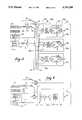
- FIG. 2is a schematic block diagram of the electronic components of the present invention for an active antenna array with an isolated transmit/receive module switched for test in the receive mode;
- FIG. 3is a schematic block diagram of the electronic components of the present invention for an active antenna array with an isolated transmit/receive module switched for test in the transmit mode;
- FIG. 4is a schematic block diagram of the electronic components of the present invention for a passive antenna.
- the antenna 10includes a ground plane 12 on which a plurality of parallel plates are mounted to establish a series of parallel plate wave guides.
- a plurality of monopole radiating elementsare mounted along the wave guide between the plates 14 and 16.
- a single wire transmission line 20is positioned in the wave guide for coupling with the radiating elements 18.
- a coaxial line 22connects individual radiating elements 18 with components (not shown in FIG. 1) for transmitting signals with the antenna 10, and the transmission line 20 is connectable with a signal injector feed 24.
- FIG. 2it will be seen that a transmitter 26, of any type well known in the art, is connected to a power amplifier 28.
- the output of the power amplifier 28is connected to a transmitter switch 30 which, when closed, connects the transmitter 26 to a transmit row feed 32.
- a transmitter switch 30When open, this connection between transmitter 26 and transmit row feed 32 is broken and signals from transmitter 26 are coupled to the signal injector feed 24 through a coupler 34.
- a line switch 36is positioned to connect signal injector feed 24 with the transmission line 20 when in one of its switching configurations.
- the phased array antenna 10 of the present inventionincludes a plurality of transmit/receive (T/R) modules 38.
- the modules 38 a, b, and care, of course, only exemplary. As will be appreciated by the skilled artisan, there are many more such T/R modules 38 in a typical phased array antenna 10.
- the T/R module 38ais singled out here only for purposes of disclosure.
- each module 38 in the antenna 10establishes the phase and amplitude of the portion of the signal radiated from the associated radiating element 18 of the antenna 10.
- the T/R modules 38are of a L-BAND type which is manufactured by Hughes Aircraft Company, Ground Systems Group.
- the T/R module 38ahas a high power T/R switch 40a which connects the T/R module 38a and the radiating element 18a.
- High power T/R switch 40ais also connected with the receive path components 42 (including low noise amplifier and limiter) in T/R module 38a and these receive path components 42 are, in turn connected with an intermediate switch 44.
- the switch 44is connected to one port of a phase shifter 46 and the other port of phase shifter 46 is connected to a low power T/R switch 48a.
- the T/R module 38ais connectable with a receive column feed 50 through the low power T/R switch 48a.
- the receive column feed 50is in connection with a receive switch 52 which connects the receive column feed 50 with a receiver and an analog to digital A/D converter 54.
- Digital signals from the A/D converter 54are passed to a performance monitor 56 where the signal is compared with preprogrammed input from a microprocessor 58 and then analyzed for future use in determining the operation status of the antenna 10.
- a receive signal pathis established through the T/R module 38a.
- the transmitter 26is coupled to the signal injector feed 24 to transmit a signal from the transmitter to the transmission line 20.
- the radiating element 18a of T/R module 38ais then coupled with the transmission line 20 to carry the signal through T/R module 38a.
- T/R module 38ais connected through the receive feed 50 and the A/D converter 54 to pass the signal to the performance monitor 56 and complete the receive signal path.
- T/R module 38aWhile a receive signal path has been shown established through the T/R module 38a, the other T/R modules 38b et seq. are shown in a dummy mode and will not pass a signal. Specifically, the high power T/R switches 40b and c, in concert with the intermediate switches 44b and c of T/R modules 38b and c, respectively, break the signal path and place these modules 38 in a dummy mode. Consequently, only T/R module 38a is monitored. It is to be appreciated, however, that signal paths can be simultaneously established through all of the modules 38, as well as individually. Further, signal paths can be sequentially established through the T/R modules 38.
- FIG. 3provides a schematic for the transmit signal path of the antenna 10 which can be established to test the transmission capability of the antenna 10.
- the transmitter switch 30is closed to create a signal path from the transmitter 26 through the transmit row feed 32 to the transmit column feed 60.
- the low power T/R switch 48ais set for connection between transmit column feed 60 and phase shifter 46.
- the intermediate switch 44athen directs the signal through the transmit path components 62 (including high power amplifier and circulator) and high power T/R switch 40a is configured to connect T/R module 38a with the radiating element 18a.
- Radiating element 18ais, as always, positioned to be coupled with the transmission line 20 and the transmit signal path is continued through line switch 36 to connect the transmission line 20 with A/D converter 54 through the coupler 64. As with the receive signal path, the transmit signal path ends at the performance monitor 56 and the microprocessor 58.
- While the transmit signal pathcan be established through T/R module 38a as disclosed above, the other modules 38 can be placed in a dummy mode. Specifically, as shown in FIG. 3, each of the low power T/R switches 48 on the modules 38 which are not in the transmit signal path are set to not allow the passage of the signal through the particular T/R module 38. Thus, these modules 38 can be isolated. As was disclosed above for the receive signal path, a transmit signal path can be simultaneously established through all of the modules 38. Further, a transmit signal path can be established through each T/R module 38 in sequence.
- the receive signal paths and the transmit signal pathsare established through the antenna 10 by the proper and concerted operation of the switches 30, 36, 40 a-c, 44 a-c, 48 a-c, and 52.
- Thiscan be accomplished in a manner well known in the pertinent art by properly programming the microprocessor 58.
- each module 38can be individually monitored and a fault detection map generated which will precisely locate the faulty module 38. In the event all modules 38 indicate a low amplitude, the trouble may be isolated to be in either the receive feed 50 or the transmission feed 60. In any event, component replacement can be made.
- a system for monitoring a passive array antennacan be established. As shown in FIG. 4 such a system is established using a T/R module 66 which incorporates two single pole, double throw switches 68a and 68b. For this configuration the switch 68b is connected with the transmission feed 60 and a selector switch 70 can alternately connect the transmission feed 60 with either the transmitter 58 or the A/D converter 54 and performance monitor 56. Simultaneously, depending on the configuration of selector switch 70, line switch 36 can be set to couple the transmission line 20 with either the transmitter 26 or with the A/D converter 54 and performance monitor 56. Specifically, with the selector switch 70 set to connect the transmitter 26 to the transmission feed 60, line switch 36 is set to couple the transmission line 20 with the performance monitor 56.
- module 66In its normal operating mode.
- the line switch 36is set to couple the transmitter 26 with transmission 20 and the selector switch 70 is set to connect the transmission feed 60 to the performance monitor 56.
- the modules 66can be either individually or collectively test monitored for the reasons and purposes disclosed above for the modules 38 of an active phased array antenna 10.
Landscapes
- Variable-Direction Aerials And Aerial Arrays (AREA)
- Testing Electric Properties And Detecting Electric Faults (AREA)
- Radar Systems Or Details Thereof (AREA)
Abstract
Description
Claims (13)
Priority Applications (3)
| Application Number | Priority Date | Filing Date | Title |
|---|---|---|---|
| US07/688,651US5253188A (en) | 1991-04-19 | 1991-04-19 | Built-in system for antenna calibration, performance monitoring and fault isolation of phased array antenna using signal injections and RF switches |
| EP19920303032EP0509694A3 (en) | 1991-04-19 | 1992-04-06 | A built-in system for antenna calibration and performance monitoring of a phased array antenna |
| JP4098249AJPH0743405B2 (en) | 1991-04-19 | 1992-04-17 | Embedded system for phase array antenna antenna calibration, performance monitoring and fault isolation using signal injector and RF switch |
Applications Claiming Priority (1)
| Application Number | Priority Date | Filing Date | Title |
|---|---|---|---|
| US07/688,651US5253188A (en) | 1991-04-19 | 1991-04-19 | Built-in system for antenna calibration, performance monitoring and fault isolation of phased array antenna using signal injections and RF switches |
Publications (1)
| Publication Number | Publication Date |
|---|---|
| US5253188Atrue US5253188A (en) | 1993-10-12 |
Family
ID=24765224
Family Applications (1)
| Application Number | Title | Priority Date | Filing Date |
|---|---|---|---|
| US07/688,651Expired - LifetimeUS5253188A (en) | 1991-04-19 | 1991-04-19 | Built-in system for antenna calibration, performance monitoring and fault isolation of phased array antenna using signal injections and RF switches |
Country Status (3)
| Country | Link |
|---|---|
| US (1) | US5253188A (en) |
| EP (1) | EP0509694A3 (en) |
| JP (1) | JPH0743405B2 (en) |
Cited By (28)
| Publication number | Priority date | Publication date | Assignee | Title |
|---|---|---|---|---|
| US5867123A (en)* | 1997-06-19 | 1999-02-02 | Motorola, Inc. | Phased array radio frequency (RF) built-in-test equipment (BITE) apparatus and method of operation therefor |
| US6127966A (en)* | 1997-05-16 | 2000-10-03 | Telefonaktiebolaget Lm Ericsson | Method and device for antenna calibration |
| US6208287B1 (en)* | 1998-03-16 | 2001-03-27 | Raytheoncompany | Phased array antenna calibration system and method |
| US6252542B1 (en) | 1998-03-16 | 2001-06-26 | Thomas V. Sikina | Phased array antenna calibration system and method using array clusters |
| US20020103013A1 (en)* | 2001-01-31 | 2002-08-01 | Watson Stephen J. | Signal detection using a phased array antenna |
| US6445343B1 (en)* | 2000-02-16 | 2002-09-03 | Hughes Electronics Corporation | Antenna element array alignment system |
| US6563966B1 (en) | 1999-03-04 | 2003-05-13 | Finisar Corporation, Inc. | Method, systems and apparatus for providing true time delayed signals using optical inputs |
| US6573862B2 (en)* | 2000-12-12 | 2003-06-03 | Harris Corporation | Phased array antenna including element control device providing fault detection and related methods |
| US20080055150A1 (en)* | 2006-09-06 | 2008-03-06 | Garmin International, Inc. | Method and system for detecting and decoding air traffic control reply signals |
| US20080122693A1 (en)* | 2006-08-08 | 2008-05-29 | Garmin International, Inc. | Active phased array antenna for aircraft surveillance systems |
| US20080204310A1 (en)* | 2007-02-28 | 2008-08-28 | Garmin International, Inc. | Methods and systems for frequency independent bearing detection |
| US20080246649A1 (en)* | 2007-04-09 | 2008-10-09 | Honeywell International Inc. | Method for phase calibrating antennas in a radar system |
| US20080284637A1 (en)* | 2007-02-28 | 2008-11-20 | Garmin International, Inc. | Digital tas transmitter and receiver systems and methods |
| US20090109085A1 (en)* | 2006-08-07 | 2009-04-30 | Garmin International, Inc. | Method and system for calibrating an antenna array for an aircraft surveillance system |
| WO2010092082A1 (en)* | 2009-02-13 | 2010-08-19 | Socowave Technologies Limited | Communication system, apparatus and methods for calibrating an antenna array |
| US20100220003A1 (en)* | 2007-08-31 | 2010-09-02 | Bae Systems Plc | Antenna calibration |
| US20100245158A1 (en)* | 2007-08-31 | 2010-09-30 | Bae Systems Plc | Antenna calibration |
| US20100253571A1 (en)* | 2007-08-31 | 2010-10-07 | Bae Systems Plc | Antenna calibration |
| US20100253570A1 (en)* | 2007-08-31 | 2010-10-07 | Bae Systems Plc | Antenna calibration |
| US20130217343A1 (en)* | 2012-02-22 | 2013-08-22 | Mediatek Singapore Pte. Ltd. | Wireless communication unit, integrated circuit and method therefor |
| EP2747203A1 (en)* | 2012-12-18 | 2014-06-25 | Panasonic Avionics Corporation | Antenna system calibration |
| US9360549B1 (en) | 2014-06-05 | 2016-06-07 | Thales-Raytheon Systems Company Llc | Methods and apparatus for a self-calibrated signal injection setup for in-field receive phased array calibration system |
| US20170040710A1 (en)* | 2015-08-09 | 2017-02-09 | The United States Of America As Represented By The Secretary Of The Navy | System including a hybrid active array |
| US10148367B1 (en)* | 2017-12-22 | 2018-12-04 | Raytheon Company | Built-in-test (BIT) for assignment-based AESA systems |
| JP2019092021A (en)* | 2017-11-14 | 2019-06-13 | 日本電気株式会社 | Connection device, inspection device, and inspection method |
| US10425172B2 (en) | 2017-12-22 | 2019-09-24 | Raytheon Company | Clutter rejecting built in test for assignment-based AESA systems |
| CN112904095A (en)* | 2021-02-05 | 2021-06-04 | 西安交通大学 | Array antenna near field calibration system and method |
| US11114757B2 (en)* | 2018-08-31 | 2021-09-07 | Rockwell Collins, Inc. | Embedded antenna array metrology systems and methods |
Families Citing this family (10)
| Publication number | Priority date | Publication date | Assignee | Title |
|---|---|---|---|---|
| US6157343A (en)* | 1996-09-09 | 2000-12-05 | Telefonaktiebolaget Lm Ericsson | Antenna array calibration |
| NL9500580A (en)* | 1995-03-27 | 1996-11-01 | Hollandse Signaalapparaten Bv | Phased array antenna equipped with a calibration network. |
| KR20040052064A (en)* | 2002-12-13 | 2004-06-19 | 엘지전자 주식회사 | A device of revising phase error for array antenna |
| JP5038708B2 (en)* | 2006-12-27 | 2012-10-03 | 株式会社東芝 | DVOR apparatus and sideband antenna abnormality detection method |
| JP2010071653A (en)* | 2008-09-16 | 2010-04-02 | Japan Radio Co Ltd | Distance measuring device |
| FR2960100B1 (en)* | 2010-05-12 | 2013-02-15 | Thales Sa | CALIBRATIONS OF AN ELECTRONIC SCANNING ANTENNA COMPRISING A NETWORK OF RADIANT ELEMENTS |
| JP5605422B2 (en)* | 2012-11-21 | 2014-10-15 | 日本電気株式会社 | Radar apparatus and radar apparatus monitoring method |
| CN110609260B (en)* | 2019-10-25 | 2021-08-31 | 北京无线电测量研究所 | T/R module test circuit |
| CN113866522B (en)* | 2021-12-07 | 2022-02-22 | 成都锐芯盛通电子科技有限公司 | Directional diagram test method and system of phased array antenna |
| CN114814692B (en)* | 2022-03-11 | 2024-10-15 | 中国科学技术大学 | Self-calibration method and storage medium based on phased array chip state RMS error calculation |
Citations (2)
| Publication number | Priority date | Publication date | Assignee | Title |
|---|---|---|---|---|
| US4949090A (en)* | 1988-02-22 | 1990-08-14 | Mitsubishi Denki Kabushiki Kaisha | Transmit/receive module test system |
| US5086302A (en)* | 1991-04-10 | 1992-02-04 | Allied-Signal Inc. | Fault isolation in a Butler matrix fed circular phased array antenna |
Family Cites Families (1)
| Publication number | Priority date | Publication date | Assignee | Title |
|---|---|---|---|---|
| JPS6340403A (en)* | 1986-08-06 | 1988-02-20 | Mitsubishi Electric Corp | Antenna diagnosing device |
- 1991
- 1991-04-19USUS07/688,651patent/US5253188A/ennot_activeExpired - Lifetime
- 1992
- 1992-04-06EPEP19920303032patent/EP0509694A3/ennot_activeWithdrawn
- 1992-04-17JPJP4098249Apatent/JPH0743405B2/ennot_activeExpired - Lifetime
Patent Citations (2)
| Publication number | Priority date | Publication date | Assignee | Title |
|---|---|---|---|---|
| US4949090A (en)* | 1988-02-22 | 1990-08-14 | Mitsubishi Denki Kabushiki Kaisha | Transmit/receive module test system |
| US5086302A (en)* | 1991-04-10 | 1992-02-04 | Allied-Signal Inc. | Fault isolation in a Butler matrix fed circular phased array antenna |
Cited By (42)
| Publication number | Priority date | Publication date | Assignee | Title |
|---|---|---|---|---|
| US6127966A (en)* | 1997-05-16 | 2000-10-03 | Telefonaktiebolaget Lm Ericsson | Method and device for antenna calibration |
| US5867123A (en)* | 1997-06-19 | 1999-02-02 | Motorola, Inc. | Phased array radio frequency (RF) built-in-test equipment (BITE) apparatus and method of operation therefor |
| US6208287B1 (en)* | 1998-03-16 | 2001-03-27 | Raytheoncompany | Phased array antenna calibration system and method |
| US6252542B1 (en) | 1998-03-16 | 2001-06-26 | Thomas V. Sikina | Phased array antenna calibration system and method using array clusters |
| US6563966B1 (en) | 1999-03-04 | 2003-05-13 | Finisar Corporation, Inc. | Method, systems and apparatus for providing true time delayed signals using optical inputs |
| US6445343B1 (en)* | 2000-02-16 | 2002-09-03 | Hughes Electronics Corporation | Antenna element array alignment system |
| US6573862B2 (en)* | 2000-12-12 | 2003-06-03 | Harris Corporation | Phased array antenna including element control device providing fault detection and related methods |
| US20020103013A1 (en)* | 2001-01-31 | 2002-08-01 | Watson Stephen J. | Signal detection using a phased array antenna |
| US7576686B2 (en) | 2006-08-07 | 2009-08-18 | Garmin International, Inc. | Method and system for calibrating an antenna array for an aircraft surveillance system |
| US20090109085A1 (en)* | 2006-08-07 | 2009-04-30 | Garmin International, Inc. | Method and system for calibrating an antenna array for an aircraft surveillance system |
| US7439901B2 (en)* | 2006-08-08 | 2008-10-21 | Garmin International, Inc. | Active phased array antenna for aircraft surveillance systems |
| US20080122693A1 (en)* | 2006-08-08 | 2008-05-29 | Garmin International, Inc. | Active phased array antenna for aircraft surveillance systems |
| US20080055150A1 (en)* | 2006-09-06 | 2008-03-06 | Garmin International, Inc. | Method and system for detecting and decoding air traffic control reply signals |
| US20080204310A1 (en)* | 2007-02-28 | 2008-08-28 | Garmin International, Inc. | Methods and systems for frequency independent bearing detection |
| US20080284637A1 (en)* | 2007-02-28 | 2008-11-20 | Garmin International, Inc. | Digital tas transmitter and receiver systems and methods |
| US7825858B2 (en) | 2007-02-28 | 2010-11-02 | Garmin International, Inc. | Methods and systems for frequency independent bearing detection |
| US20080246649A1 (en)* | 2007-04-09 | 2008-10-09 | Honeywell International Inc. | Method for phase calibrating antennas in a radar system |
| US7522096B2 (en)* | 2007-04-09 | 2009-04-21 | Honeywell International Inc | Method for phase calibrating antennas in a radar system |
| US20100253571A1 (en)* | 2007-08-31 | 2010-10-07 | Bae Systems Plc | Antenna calibration |
| US8085189B2 (en)* | 2007-08-31 | 2011-12-27 | Bae Systems Plc | Antenna calibration |
| US20100220003A1 (en)* | 2007-08-31 | 2010-09-02 | Bae Systems Plc | Antenna calibration |
| US20100253570A1 (en)* | 2007-08-31 | 2010-10-07 | Bae Systems Plc | Antenna calibration |
| US20100245158A1 (en)* | 2007-08-31 | 2010-09-30 | Bae Systems Plc | Antenna calibration |
| US7990312B2 (en) | 2007-08-31 | 2011-08-02 | Bae Systems Plc | Antenna calibration |
| US8004456B2 (en) | 2007-08-31 | 2011-08-23 | Bae Systems Plc | Antenna calibration |
| US8004457B2 (en) | 2007-08-31 | 2011-08-23 | Bae Systems Plc | Antenna calibration |
| WO2010092082A1 (en)* | 2009-02-13 | 2010-08-19 | Socowave Technologies Limited | Communication system, apparatus and methods for calibrating an antenna array |
| CN102396105A (en)* | 2009-02-13 | 2012-03-28 | 索科波技术有限公司 | Communication system, apparatus and methods for calibrating an antenna array |
| US9035828B2 (en) | 2009-02-13 | 2015-05-19 | Socowave Technologies, Ltd. | Communication system, apparatus and methods for calibrating an antenna array |
| CN102396105B (en)* | 2009-02-13 | 2015-01-07 | 索科波技术有限公司 | Communication system, apparatus and methods for calibrating an antenna array |
| US20130217343A1 (en)* | 2012-02-22 | 2013-08-22 | Mediatek Singapore Pte. Ltd. | Wireless communication unit, integrated circuit and method therefor |
| US9338664B2 (en)* | 2012-02-22 | 2016-05-10 | Mediatek Singapore Pte. Ltd. | Wireless communication unit, integrated circuit and method therefor |
| EP2747203A1 (en)* | 2012-12-18 | 2014-06-25 | Panasonic Avionics Corporation | Antenna system calibration |
| US8964891B2 (en) | 2012-12-18 | 2015-02-24 | Panasonic Avionics Corporation | Antenna system calibration |
| US9360549B1 (en) | 2014-06-05 | 2016-06-07 | Thales-Raytheon Systems Company Llc | Methods and apparatus for a self-calibrated signal injection setup for in-field receive phased array calibration system |
| US20170040710A1 (en)* | 2015-08-09 | 2017-02-09 | The United States Of America As Represented By The Secretary Of The Navy | System including a hybrid active array |
| US9742075B2 (en)* | 2015-08-09 | 2017-08-22 | The United States Of America As Represented By The Secretary Of The Navy | System including a hybrid active array |
| JP2019092021A (en)* | 2017-11-14 | 2019-06-13 | 日本電気株式会社 | Connection device, inspection device, and inspection method |
| US10148367B1 (en)* | 2017-12-22 | 2018-12-04 | Raytheon Company | Built-in-test (BIT) for assignment-based AESA systems |
| US10425172B2 (en) | 2017-12-22 | 2019-09-24 | Raytheon Company | Clutter rejecting built in test for assignment-based AESA systems |
| US11114757B2 (en)* | 2018-08-31 | 2021-09-07 | Rockwell Collins, Inc. | Embedded antenna array metrology systems and methods |
| CN112904095A (en)* | 2021-02-05 | 2021-06-04 | 西安交通大学 | Array antenna near field calibration system and method |
Also Published As
| Publication number | Publication date |
|---|---|
| JPH0743405B2 (en) | 1995-05-15 |
| EP0509694A2 (en) | 1992-10-21 |
| EP0509694A3 (en) | 1994-07-27 |
| JPH05142277A (en) | 1993-06-08 |
Similar Documents
| Publication | Publication Date | Title |
|---|---|---|
| US5253188A (en) | Built-in system for antenna calibration, performance monitoring and fault isolation of phased array antenna using signal injections and RF switches | |
| CA2324273C (en) | Phased array antenna calibration system and method using array clusters | |
| US4864315A (en) | Phased array antenna testing arrangement | |
| US6208287B1 (en) | Phased array antenna calibration system and method | |
| US5864317A (en) | Simplified quadrant-partitioned array architecture and measure sequence to support mutual-coupling based calibration | |
| US5682165A (en) | Active array self calibration | |
| US5493304A (en) | Calibration system for wide band array using true-time-delay beamsteering | |
| EP3824572A1 (en) | System and method for over-the-air (ota) testing to detect faulty elements in an active array antenna of an extremely high frequency (ehf) wireless communication device | |
| CN107219526B (en) | Calibration system and method in double-star Ka FMCW SAR and imaging system | |
| US7038633B2 (en) | Antenna system and net drift verification | |
| US6121925A (en) | Data-link and antenna selection assembly | |
| GB2289798A (en) | Improvements relating to radar antenna systems | |
| CA1193713A (en) | Self contained antenna test device | |
| WO2020180708A1 (en) | Systems and methods for automated testing and calibration of phased array antenna systems | |
| US11705974B2 (en) | Efficient in-situ radiative loop-back AESA calibration and prognostic health monitoring | |
| US4700192A (en) | Test configuration and procedure for determining the operational status of a phased array antenna | |
| Lee et al. | A performance monitoring/fault isolation and correction system of a phased array antenna using transmission-line signal injection with phase toggling method | |
| JP2674165B2 (en) | Phased array radar system | |
| US20210211210A1 (en) | Beamforming Device Testing | |
| Thompson et al. | Huffman Radar Site: Far-Field Calibration and Testing Range | |
| CN120016159A (en) | A phased array antenna system based on secondary radar and its use method | |
| JPH02309278A (en) | Active phased-array radar |
Legal Events
| Date | Code | Title | Description |
|---|---|---|---|
| AS | Assignment | Owner name:HUGHES AIRCRAFT COMPANY, LOS ANGELES, CA A DE CORP Free format text:ASSIGNMENT OF ASSIGNORS INTEREST.;ASSIGNORS:LEE, KUAN M.;CHU, RUEY S.;LIU, SIEN-CHANG C.;REEL/FRAME:005684/0252 Effective date:19910416 | |
| STCF | Information on status: patent grant | Free format text:PATENTED CASE | |
| FEPP | Fee payment procedure | Free format text:PAYOR NUMBER ASSIGNED (ORIGINAL EVENT CODE: ASPN); ENTITY STATUS OF PATENT OWNER: LARGE ENTITY | |
| FPAY | Fee payment | Year of fee payment:4 | |
| FEPP | Fee payment procedure | Free format text:PAYOR NUMBER ASSIGNED (ORIGINAL EVENT CODE: ASPN); ENTITY STATUS OF PATENT OWNER: LARGE ENTITY | |
| FEPP | Fee payment procedure | Free format text:PAYER NUMBER DE-ASSIGNED (ORIGINAL EVENT CODE: RMPN); ENTITY STATUS OF PATENT OWNER: LARGE ENTITY | |
| FPAY | Fee payment | Year of fee payment:8 | |
| AS | Assignment | Owner name:HE HOLDINGS, INC., A DELAWARE CORP., CALIFORNIA Free format text:CHANGE OF NAME;ASSIGNOR:HUGHES AIRCRAFT COMPANY, A CORPORATION OF THE STATE OF DELAWARE;REEL/FRAME:016087/0541 Effective date:19971217 Owner name:RAYTHEON COMPANY, MASSACHUSETTS Free format text:MERGER;ASSIGNOR:HE HOLDINGS, INC. DBA HUGHES ELECTRONICS;REEL/FRAME:016116/0506 Effective date:19971217 | |
| FPAY | Fee payment | Year of fee payment:12 |