US5253059A - Method and circuit for adjusting the size of a video frame - Google Patents
Method and circuit for adjusting the size of a video frameDownload PDFInfo
- Publication number
- US5253059A US5253059AUS07/884,730US88473092AUS5253059AUS 5253059 AUS5253059 AUS 5253059AUS 88473092 AUS88473092 AUS 88473092AUS 5253059 AUS5253059 AUS 5253059A
- Authority
- US
- United States
- Prior art keywords
- coding
- frame
- horizontal
- frames
- video
- Prior art date
- Legal status (The legal status is an assumption and is not a legal conclusion. Google has not performed a legal analysis and makes no representation as to the accuracy of the status listed.)
- Expired - Lifetime
Links
- 238000000034methodMethods0.000titleclaimsdescription23
- 230000005540biological transmissionEffects0.000claimsdescription9
- 238000001914filtrationMethods0.000claimsdescription2
- 230000001419dependent effectEffects0.000claims1
- 238000007781pre-processingMethods0.000abstractdescription23
- 238000005070samplingMethods0.000abstractdescription8
- 230000007423decreaseEffects0.000abstractdescription4
- 230000001934delayEffects0.000description4
- 230000006835compressionEffects0.000description3
- 238000007906compressionMethods0.000description3
- 238000005549size reductionMethods0.000description3
- 230000002123temporal effectEffects0.000description3
- 238000006243chemical reactionMethods0.000description2
- 230000003044adaptive effectEffects0.000description1
- 230000003247decreasing effectEffects0.000description1
- 230000000694effectsEffects0.000description1
- 238000009499grossingMethods0.000description1
- 238000013139quantizationMethods0.000description1
Images


Classifications
- H—ELECTRICITY
- H04—ELECTRIC COMMUNICATION TECHNIQUE
- H04N—PICTORIAL COMMUNICATION, e.g. TELEVISION
- H04N7/00—Television systems
- H04N7/01—Conversion of standards, e.g. involving analogue television standards or digital television standards processed at pixel level
- H04N7/0102—Conversion of standards, e.g. involving analogue television standards or digital television standards processed at pixel level involving the resampling of the incoming video signal
- H—ELECTRICITY
- H04—ELECTRIC COMMUNICATION TECHNIQUE
- H04N—PICTORIAL COMMUNICATION, e.g. TELEVISION
- H04N19/00—Methods or arrangements for coding, decoding, compressing or decompressing digital video signals
- H04N19/10—Methods or arrangements for coding, decoding, compressing or decompressing digital video signals using adaptive coding
- H04N19/102—Methods or arrangements for coding, decoding, compressing or decompressing digital video signals using adaptive coding characterised by the element, parameter or selection affected or controlled by the adaptive coding
- H04N19/117—Filters, e.g. for pre-processing or post-processing
- H—ELECTRICITY
- H04—ELECTRIC COMMUNICATION TECHNIQUE
- H04N—PICTORIAL COMMUNICATION, e.g. TELEVISION
- H04N19/00—Methods or arrangements for coding, decoding, compressing or decompressing digital video signals
- H04N19/10—Methods or arrangements for coding, decoding, compressing or decompressing digital video signals using adaptive coding
- H04N19/134—Methods or arrangements for coding, decoding, compressing or decompressing digital video signals using adaptive coding characterised by the element, parameter or criterion affecting or controlling the adaptive coding
- H04N19/146—Data rate or code amount at the encoder output
- H04N19/152—Data rate or code amount at the encoder output by measuring the fullness of the transmission buffer
- H—ELECTRICITY
- H04—ELECTRIC COMMUNICATION TECHNIQUE
- H04N—PICTORIAL COMMUNICATION, e.g. TELEVISION
- H04N19/00—Methods or arrangements for coding, decoding, compressing or decompressing digital video signals
- H04N19/10—Methods or arrangements for coding, decoding, compressing or decompressing digital video signals using adaptive coding
- H04N19/169—Methods or arrangements for coding, decoding, compressing or decompressing digital video signals using adaptive coding characterised by the coding unit, i.e. the structural portion or semantic portion of the video signal being the object or the subject of the adaptive coding
- H04N19/17—Methods or arrangements for coding, decoding, compressing or decompressing digital video signals using adaptive coding characterised by the coding unit, i.e. the structural portion or semantic portion of the video signal being the object or the subject of the adaptive coding the unit being an image region, e.g. an object
- H04N19/172—Methods or arrangements for coding, decoding, compressing or decompressing digital video signals using adaptive coding characterised by the coding unit, i.e. the structural portion or semantic portion of the video signal being the object or the subject of the adaptive coding the unit being an image region, e.g. an object the region being a picture, frame or field
- H—ELECTRICITY
- H04—ELECTRIC COMMUNICATION TECHNIQUE
- H04N—PICTORIAL COMMUNICATION, e.g. TELEVISION
- H04N19/00—Methods or arrangements for coding, decoding, compressing or decompressing digital video signals
- H04N19/50—Methods or arrangements for coding, decoding, compressing or decompressing digital video signals using predictive coding
- H04N19/59—Methods or arrangements for coding, decoding, compressing or decompressing digital video signals using predictive coding involving spatial sub-sampling or interpolation, e.g. alteration of picture size or resolution
- H—ELECTRICITY
- H04—ELECTRIC COMMUNICATION TECHNIQUE
- H04N—PICTORIAL COMMUNICATION, e.g. TELEVISION
- H04N19/00—Methods or arrangements for coding, decoding, compressing or decompressing digital video signals
- H04N19/60—Methods or arrangements for coding, decoding, compressing or decompressing digital video signals using transform coding
- H04N19/61—Methods or arrangements for coding, decoding, compressing or decompressing digital video signals using transform coding in combination with predictive coding
- H—ELECTRICITY
- H04—ELECTRIC COMMUNICATION TECHNIQUE
- H04N—PICTORIAL COMMUNICATION, e.g. TELEVISION
- H04N19/00—Methods or arrangements for coding, decoding, compressing or decompressing digital video signals
- H04N19/80—Details of filtering operations specially adapted for video compression, e.g. for pixel interpolation
- H—ELECTRICITY
- H04—ELECTRIC COMMUNICATION TECHNIQUE
- H04N—PICTORIAL COMMUNICATION, e.g. TELEVISION
- H04N19/00—Methods or arrangements for coding, decoding, compressing or decompressing digital video signals
- H04N19/10—Methods or arrangements for coding, decoding, compressing or decompressing digital video signals using adaptive coding
- H04N19/134—Methods or arrangements for coding, decoding, compressing or decompressing digital video signals using adaptive coding characterised by the element, parameter or criterion affecting or controlling the adaptive coding
- H04N19/146—Data rate or code amount at the encoder output
Definitions
- the present inventionrelates to a method and circuit for coding video signals. More specifically, the present invention relates to a technique for adjusting the size of a frame of video to be coded to control the amount of bits generated by a video coding circuit.
- Video servicescan be provided to subscribers by compressing a video signal using a coding circuit at a transmitting station.
- the compressed video signalis then transmitted via a telecommunication network such as a packet network to a remotely located subscriber station.
- the video signalis decompressed through use of a decoding circuit to reconstruct the original signal. It is expected that High Definition Television (HDTV) signals will be transmitted to subscribers in this manner.
- HDMIHigh Definition Television
- a video coding circuitincludes a processor for performing an orthogonal transform such as a discrete cosine transfer (DCT) and a quantizer for quantizing the transform coefficients resulting from the orthogonal transform.
- the coding circuitcan code a frame of video using an intra-frame or an inter-frame compression technique.
- a frame of video to be codedis divided into blocks of pixels which may be 8 ⁇ 8 or 16 ⁇ 16 blocks. If the frame is coded using an intra-frame compression technique, the orthogonal transform is applied directly to each block of pixels and the resulting transform coefficients are quantized.
- the predictionis a motion-compensated prediction based on a previous frame.
- Some video coding circuitsutilize only the intra-frame mode while other video coding circuits code some frames with an intra-frame mode and some frames with an inter-frame mode.
- the quantized transform coefficientsare converted by a coder into variable length (VLC) or fixed length (FLC) code words for transmission to a remote location.
- the codercomprises a run-length coder followed by a variable length coder.
- an intra-frame coding moderesults in more code bits than an inter-frame coding mode.
- busy frames and frame portionsresult in the generation of more code bits than smooth frames and frame portions.
- a video coding circuitgenerates code bits at a variable bit rate.
- Some networkscan handle the local fluctuations in bit rate produced by the coding circuit and the code bits are transmitted at a variable bit rate directly into the network.
- the rate smoothingcan be accomplished by use of a rate buffer which interfaces between the coding circuit and the network. Code bits are written into the rate buffer at a variable rate by the coding circuit and transmitted from the rate buffer into the network at a desired constant or approximately constant rate. To carry out this scheme, it is necessary to maintain the fraction of the rate buffer which is occupied within predetermined upper and lower limits. Thus, in a typical scheme, the contents of the rate buffer are fed back to the coding circuit to control the amount of code bits generated by the coding circuit.
- the prior artdiscloses a number of techniques for controlling the rate at which code bits are generated by the coding circuit.
- the coarseness of the quantizermay be adjusted (see e.g. W. Chen and W. K. Pratt, "Scene Adaptive Coder", IEEE Trans. Commun., Vol. COM-32, pp. 225-232, March 1984 and C. T. Chen et al, U.S. patent application Ser. No. 381,860 filed Jul. 19, 1989 and assigned to the assignee hereof).
- a coarse quantizeri.e. a quantizer with a large step size
- results in fewer code bits than a fine quantizeri.e. a quantizer with a small step size.
- a problem with this approach for controlling the rate at which code bits are generated by a video coding circuitis that unacceptable artifacts may be produced when the quantizer is made very coarse to fit the signal within a specified bandwidth.
- the source signalis decimated horizontally and vertically by a factor of two to obtain a quarter-size frame.
- use of a quarter-size framecan result in a coded image which is of poor quality.
- the drastic reduction in samples which occurs when there is a conversion to a quarter-size framemakes it difficult to achieve a desired amount of code bits while also maintaining a desired level of quality in the coded video signal.
- the coding algorithmcannot make up for the reduced number of samples in a quarter-size frame through quantization with a fine quantizer having a very small step size. There is a range of rates for which using a fine quantizer does not make up for the loss of quality resulting from use of a quarter-size frame in forming a coded image.
- the present inventionuses a coding circuit and coding method which achieve a more gradual reduction in frame size than the reduction to quarter-size frames utilized in the prior art.
- the present inventionutilizes spatial reduction of M/N in each of the horizontal and vertical dimensions for a total frame size reduction of M 2 /N 2 , where M and N are integers and where O ⁇ M/N ⁇ 1.
- the normal procedure for a conversion by a factor M/Nconsists of first using interpolation (sampling rate increase) by a factor of M followed by decimation (sampling rate decrease) by a factor of N (see e.g., R. E. Crochiere et al., "Multirate Digital Signal Processing", Prentice Hall, Englewood Cliffs, N.J., 1983)
- these interpolation and decimation operationsare carried out using periodically shift-varying filters that are derived from interpolation and decimation filters using a polyphase representation.
- filtersare quite complex and are difficult to implement, especially when the flexibility to select among different M/N ratios is desired.
- One reason for the difficulty in achieving flexibilityis that the polyphase periodically shift-varying filters combine both low pass anti-aliasing filtering and interpolation and decimation.
- a video coding circuitincludes a preprocessing stage and a coding stage.
- the inventionmay utilize any type of coding stage.
- the coding stageincludes a processor for performing a discrete cosine transform and a quantizer for quantizing the discrete cosine transform coefficients.
- the coding stagemay utilize an intra-frame or an inter-frame compression technique.
- the preprocessing stageachieves a desired reduction in frame size to control the number of bits generated by the coding stage.
- the input to the preprocessing stageis a sequence of full-size video frames.
- the output of the preprocessing stageis a sequence of video frames of reduced size. This sequence of video frames of reduced size is input into the coding stage which outputs a coded video signal for transmission to a remotely located decoder.
- the frames of videoare processed by both low pass anti-aliasing filters and shift varying sample reduction filters.
- the video framesare filtered in the horizontal direction by a low pass anti-aliasing filter with a normalized cutoff frequency which is equal to or less than M H ⁇ /N H .
- the video framesare also filtered in the vertical direction by a low pass anti-aliasing filter with a normalized cutoff frequency which is equal to or less than M v ⁇ /N v .
- the desired reduction factor in the horizontal directionis M H /N H and the desired reduction factor is in the vertical direction is M v /N v , wherein M H ,N H , M v , and N v are non-negative integers.
- the desired reduction factoris the same in the horizontal and vertical directions and is represented by M/N.
- the low pass filters for the horizontal and vertical directionsare implemented by finite impulse response (FIR) linear transverse filters.
- FIRfinite impulse response
- a lookup tableis associated with each of the filters to provide the filter coefficients for a selected value of M/N or for selected values of M N /N N and M v /N v .
- the vertical and horizontal low pass filtersdo not change the number of pixel values (i.e. samples) in a frame. These filters only eliminate frequency components which are above the cutoff in both dimensions to suppress the aliasing that normally occurs due to reducing the number of samples in a frame.
- a shift varying filteris then applied horizontally and vertically.
- a first particular shift varying filter out of a plurality of available shift varying filtersis selected to reduce the horizontal sample rate by a selected value of M H /N H .
- a second particular shift varying filteris selected to reduce the vertical sampling rate by a selected value M v /N v .
- the resulting reduced size framesare then coded by the coding stage and transmitted to a remotely located subscriber station.
- the arriving coded signalis decoded to reconstruct the reduced-size frames.
- the reduced-size framesare interpolated at the subscriber station to restore the original sampling rate if this is required by a display at the subscriber station.
- the preprocessing stageincludes a plurality of low pass filters and a plurality of shift varying filters for the horizontal and vertical directions corresponding to different values of M/N or M H /N H and M v /N v .
- a feedback signal from the network or from a rate buffer which interfaces the coding stage to the networkis applied to the preprocessing stage to select the desired frame size reduction factor to control the number of code bits generated by the coding stage.
- the inventive preprocessing stagemay be used in combination with a technique for controlling the step size of the quantizer used in the coding stage to further control the number of bits generated by the coding stage.
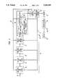
- FIG. 1schematically illustrates a video coding circuit in accordance with an illustrative embodiment of the present invention.
- FIGS. 2A, 2B, 2C, and 2Dillustrate the transmission characteristics of low pass filters utilized in the coding circuit of FIG. 1.
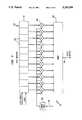
- FIG. 3schematically illustrates a low pass filter for use in the coding circuit of FIG. 1.
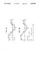
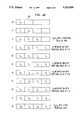
- FIGS. 4A, 4B, 4C and 4Dschematically illustrate the operation of a shift varying filter for use in the coding circuit of FIG. 1.
- FIG. 1schematically illustrates a video coding circuit 10, a transmission network 20 and a remotely located subscriber station 30.
- the coding circuit 10includes a preprocessing stage 40 and a coding stage 50.
- the purpose of the preprocessing stage 40is to receive frames of video to be coded at the input 41 and to reduce the size of the frames by a particular reduction factor.
- the reduced-size framesare outputted at the output 42 of the preprocessing stage 40 and are transmitted to the coding stage 50 at the input 51.
- the coding stage 50converts each frame into a series of code bits at the output 52.
- the number of code bits generated by the coding stage 50 for each framedepends on the reduction factor used by the preprocessing stage 40 to reduce the frame size. Thus by controlling the reduction factor utilized by the preprocessing stage 40, it is possible to control the number of code bits generated for a frame by the coding stage 50.
- the coding stage 50is now considered.
- the present inventionis applicable for any video coding scheme. For purposes of illustration, one particular coding scheme is briefly described herein.
- the coding stage 50comprises a DCT processor 53, a quantizer 54, a predictive error processor 55 and a coder 56.
- a coding stagesuch as the coding stage 50 can code in an intra-frame and in an interframe (e.g., a predictive) mode.
- the frameis divided into blocks of pixels such as 8 ⁇ 8 or 16 ⁇ 16 blocks.
- the DCT processor 53applies a DCT transform to each block of pixels and the resulting transform coefficients are quantized by the quantizer 54.
- the resulting coefficientsare then coded by the coder 56.
- the coder 56is, for example, a variable length coder or a run length coder in combination with a variable length coder.
- the output of the quantizer 54is fed to the predictive error processor 56.
- the predictive error processorincludes an inverse quantizer and an inverse DCT processor for reconstructing each block of pixels.
- the reconstructed blocks of pixelsare stored for use in coding earlier or later frames in an inter-frame mode.
- each block of pixelsis transmitted to the predictive error processor 55.
- the predictive error processor 55outputs a predictive error.
- the predictive erroris the difference between the input block of pixels and a motion compensated prediction from a previous frame which is stored in the predictive error processor 55.
- the block of pixelsis directly coded by the DCT processor 53 and quantizer 54 or the predictive error is coded by the DCT processor 53 and quantizer 54. In either case, the resulting quantized transform coefficients are processed by the coder 56 to generate code bits.
- the coder 56may be a variable length or a fixed length coder.
- the first frameis typically intra-frame coded and the remainder of the frames are inter-frame coded.
- code bitsare generated at a constant or a variable rate.
- the bit rate at the output 52is variable, depending for example on whether intra-frame or predictive coding is used for a given frame, as predictive coding results in fewer code bits than intra-frame coding.
- the number of bits generatedvaries with image content, with busy portions of frames resulting in more code bits than still portions of frames.
- the optional rate buffer 60is utilized.
- the code bits generated by the coding stage 50are transmitted directly into the network 20 at a variable rate.
- the coding stage 50is directly connected to the transmission network 20 is considered first. In some situations, such as when there is network congestion, it may be desirable to reduce the average rate at which code bits are produced by the coding stage 50.
- the network 20transmits via the feedback path 70 a signal to the preprocessing stage 40.
- the feedback signalis utilized by the preprocessing stage 40 to determine a frame reduction factor which in turn determines the size of the frames at the preprocessing stage output 42. For example, if it is desired to reduce the number of code bits produced by the coding stage 50 because of congestion in the network 20, the feedback path 70 transmits a signal which causes the frame size to be reduced.
- the size of reductionmay be established once per group of frames.
- the rate buffer 60receives code bits at a variable rate from the coding stage 50 and transmits code bits into the network 20 at a constant rate.
- the fraction of the rate buffer which is occupiedhas to be maintained between certain upper and lower limits.
- a signal indicative of the occupancy fraction of the bufferis fed back via the feedback path 70' to the preprocessing stage 40 to control the frame size, and therefore, the number of bits generated by the coding stage 50. If the occupancy of the rate buffer 60 is too low, the frame size is increased to increase the number of code bits produced by the coding stage 50. If the occupancy of the buffer 60 is too high, the frame size is decreased to decrease the number of code bits produced by the coding stage 50.
- the code bits generated by the coding stage 50are transmitted to the remotely located subscriber station 30.
- the subscriber station 30comprises a decoder 31, which reconstructs the reduced-size frames by reversing the operations of the coding stage 50, and an interpolator 32 which increases the size of the reduced-size frames back to full-size (i.e., reversing the frame size reducing operation of the preprocessing stage 40) if this is required by the display 33.
- the preprocessing stage 40comprises a horizontal low pass filter 43, a vertical low pass filter 44, a horizontal shift varying filter 45 and a vertical shift varying filter 46.
- Full-size video framesare received at the input 41 of the stage 40.
- the framesare processed in the horizontal and vertical directions by the low pass filters 43 and 44 and then the number of samples in the horizontal and vertical directions is reduced by the shift varying filters 45 and 46 to generate reduced-sized frames at the output 42.
- the cutoff frequency of the horizontal low pass filter 43is M H ⁇ /N H and the cutoff frequency of the vertical low pass filter is M v ⁇ /N v .
- the quantities M H ⁇ /N H and M v ⁇ /N vrepresent frequencies in radians which are normalized to the Nyquist frequency. (Thus, in an unfiltered signal the range of frequencies in radians is from 0 to ⁇ ).
- M H /N His the desired reduction factor in the horizontal direction
- M v /N vis the desired reduction factor in the vertical direction.
- the horizontal and vertical reduction factorsmay be selected in response to the feedback signals transmitted via the path 70 from the network 20 or via the path 70' from the rate buffer 60, if such a rate buffer is utilized.
- N H and N vare set to 8 and M H and M v may be selected from 4, 5, 6 and 7.
- the low pass filters 45 and 46may be implemented using finite impulse response filters with monotone passband frequency responses.
- a lookup tableis provided so that different filter coefficients can be selected corresponding to different values of M H /N H and M v /N v .
- the quality of the reconstructed signal at the subscriber station 30depends on the responses of the filters utilized.
- the filtersare of duration eleven (see FIG. 3) and the frequency responses are such that they result in some but not excessive aliasing.
- Each of the filters 43 and 44comprises a shift register 110 for storing video samples.
- the shift register 110illustratively comprises eleven individual storage elements 120. At each clock cycle, all the video samples are shifted one location to the right, the rightmost sample is eliminated, and a new sample is stored in the leftmost storage element. For each clock cycle, an output sample appears at the output 130.
- Each output sampleis a weighted sum of the input samples stored in the storage elements 120. To obtain the weighted sum, each of the samples stored in the storage elements 120 is multiplied by a weighting coefficient using a multiplier 140. The outputs of the multipliers 140 are added by the adder 145 to obtain an output sample at the output 130.
- the horizontal shift varying filter 45reduces the number of samples in the horizontal direction by M H /N H and the vertical shift varying filter 46 reduces the number of samples in the vertical direction by M v /N v .
- FIG. 4Ashows the temporal locations of nine input samples for the shift varying filter 45.
- the input samplesare labeled i 0 , i 7 , . . . ,i 8 .
- the temporal spacing between the input samplesis T.
- the sample spacingis about 9.6 ⁇ 10 -8 seconds.
- FIG. 4Bshows the locations of the output samples 0 0 ,0 1 , . . . ,0 5 . Relative to the input samples, the temporal spacing of the output samples is 1.6 T.
- the output sample O 0is obtained by retaining the input sample i 0 .
- the output sample O 1is a weighted sum of the two nearest preceding and two nearest succeeding input samples i 0 ,i 1 ,i 2 and i 3 .
- the output sample O 2is a weighted sum of the two nearest preceding and two nearest succeeding input samples i 2 ,i 3 ,i 4 and i 5 .
- the output sample O 3is a weighted sum of i 4 ,i 5 ,i 6 and i 7 and the output sample 0 4 is a weighted sum of i 5 ,i 6 ,i 7 and i 8 .
- the output sample O 5is obtained by retaining the input sample i 5 .
- the filter 45illustratively comprises a shift register 200 for storing the input video samples i 0 ,i 1 . . .
- the shift register 200comprises four individual storage elements 205. Four storage elements are needed because each output sample is a weighted sum of four input samples. To generate an output sample, a weighted sum of input samples is obtained using the multipliers 210.
- the weighting coefficientsare supplied by a lookup table 230 which provides specific weighting coefficients depending on a selected value of M/N. The value of M/N may be selected by a signal applied to the input 240 of the lookup table 230.
- the signal applied to the input 240 of the lookup table 230may be generated via one of the feedback paths 70 or 70' (see FIG. 1).
- the outputs of the multipliers 210are added by the adder 250.
- the variable delay 260is utilized.
- a variable delay device 260provides a sequence of delays to implement the proper output sample spacing. In the case where M/N is 5/8, fractional delays of 0, 0.6 T, 0.2 T, 0.8 T, and 0.4 T are used. This may be understood as follows:
- FIG. 4Dshows the contents of the shift register 200 at particular values of the discrete time variable nT.
- the output O 0is formed by transmitting the input sample i 1 directly to the output 270. This is accomplished by setting all the weighting coefficients to zero except the coefficient of i 1 which is set to 1 and by setting the variable delay 260 to zero.
- the number of samplesis reduced. This is accomplished in the horizontal direction using the shift varying filter 45 and in the vertical direction using the shift varying filter 46.
- the resulting reduced-size framesare then coded by the coding stage 50 in the manner described above.
- each frame of videois processed by a low pass anti-aliasing filter in the horizontal and vertical directions.
- the cutoff frequencies in the horizonal and vertical directionsare determined by a selected frame reduction factor in the corresponding direction.
- each frame of videois processed horizontally and vertically by a shift varying filter.
- the strategy of the present invention for controlling video frame sizemay be used in combination with a strategy for controlling the quantizer step size to control the number of bits utilized to code a frame of video.
- a signalmay be sent from the rate buffer 60 via path 70' to the quantizer 54 to control the quantizer step size based on buffer content, for example.
- a signalmay be sent from the network 20 via the path 70 to the quantizer 54 to control the quantizer step size.
Landscapes
- Engineering & Computer Science (AREA)
- Multimedia (AREA)
- Signal Processing (AREA)
- Compression Or Coding Systems Of Tv Signals (AREA)
Abstract
Description
Claims (11)
Priority Applications (1)
| Application Number | Priority Date | Filing Date | Title |
|---|---|---|---|
| US07/884,730US5253059A (en) | 1992-05-15 | 1992-05-15 | Method and circuit for adjusting the size of a video frame |
Applications Claiming Priority (1)
| Application Number | Priority Date | Filing Date | Title |
|---|---|---|---|
| US07/884,730US5253059A (en) | 1992-05-15 | 1992-05-15 | Method and circuit for adjusting the size of a video frame |
Publications (1)
| Publication Number | Publication Date |
|---|---|
| US5253059Atrue US5253059A (en) | 1993-10-12 |
Family
ID=25385264
Family Applications (1)
| Application Number | Title | Priority Date | Filing Date |
|---|---|---|---|
| US07/884,730Expired - LifetimeUS5253059A (en) | 1992-05-15 | 1992-05-15 | Method and circuit for adjusting the size of a video frame |
Country Status (1)
| Country | Link |
|---|---|
| US (1) | US5253059A (en) |
Cited By (43)
| Publication number | Priority date | Publication date | Assignee | Title |
|---|---|---|---|---|
| US5363213A (en)* | 1992-06-08 | 1994-11-08 | Xerox Corporation | Unquantized resolution conversion of bitmap images using error diffusion |
| US5440653A (en)* | 1993-09-24 | 1995-08-08 | Genesis Microchip Inc. | Image mirroring and image extension for digital filtering |
| US5446499A (en)* | 1992-12-23 | 1995-08-29 | Daewoo Electronics Co., Inc. | Window signal generating apparatus |
| WO1996005701A1 (en)* | 1994-08-09 | 1996-02-22 | Picturetel Corporation | Spatially adaptive blur filter |
| US5502489A (en)* | 1994-01-03 | 1996-03-26 | Daewoo Electronics Co., Ltd. | Method for the motion adaptive spatial filtering of video signals in an image coding apparatus |
| US5594495A (en)* | 1992-06-03 | 1997-01-14 | Digital Equipment Corporation | Video data scaling for video teleconferencing workstations communicating by digital data network |
| US5602599A (en)* | 1993-10-08 | 1997-02-11 | Genesis Microchip Inc. | Apparatus and method incorporating digital video processing for reduction/magnification of digital video images to produce low-pass filtered images |
| US5617135A (en)* | 1993-09-06 | 1997-04-01 | Hitachi, Ltd. | Multi-point visual communication system |
| US5631644A (en)* | 1993-12-22 | 1997-05-20 | Sharp Kabushiki Kaisha | Image encoding apparatus |
| EP0778707A3 (en)* | 1995-12-06 | 1997-07-16 | Thomson Multimedia Sa | |
| WO1998010587A1 (en)* | 1996-09-04 | 1998-03-12 | Winbond Systems Laboratory, Inc. | Moving picture camera with universal serial bus interface |
| US5731835A (en)* | 1996-02-26 | 1998-03-24 | David Sarnoff Research Center, Inc. | Dynamic coding rate control in a block-based video coding system |
| US5777679A (en)* | 1996-03-15 | 1998-07-07 | International Business Machines Corporation | Video decoder including polyphase fir horizontal filter |
| US5907363A (en)* | 1994-10-21 | 1999-05-25 | Lucent Technologies Inc. | Method for controlling a compressed data buffer |
| WO1999033273A1 (en)* | 1997-12-23 | 1999-07-01 | Thomson Licensing S.A. | Low noise encoding and decoding method |
| US5930397A (en)* | 1995-08-31 | 1999-07-27 | Sony Corporation | Apparatus and method for processing image signal |
| US6023296A (en)* | 1997-07-10 | 2000-02-08 | Sarnoff Corporation | Apparatus and method for object based rate control in a coding system |
| US6064450A (en)* | 1995-12-06 | 2000-05-16 | Thomson Licensing S.A. | Digital video preprocessor horizontal and vertical filters |
| US6101220A (en)* | 1994-12-20 | 2000-08-08 | Victor Company Of Japan, Ltd. | Method and apparatus for limiting band of moving-picture signal |
| US6160846A (en)* | 1995-10-25 | 2000-12-12 | Sarnoff Corporation | Apparatus and method for optimizing the rate control in a coding system |
| US6188729B1 (en)* | 1993-04-01 | 2001-02-13 | Scientific-Atlanta, Inc. | Method and apparatus for effecting seamless data rate changes in a video compression system |
| US6192081B1 (en) | 1995-10-26 | 2001-02-20 | Sarnoff Corporation | Apparatus and method for selecting a coding mode in a block-based coding system |
| US6243497B1 (en) | 1997-02-12 | 2001-06-05 | Sarnoff Corporation | Apparatus and method for optimizing the rate control in a coding system |
| US20010017653A1 (en)* | 2000-02-24 | 2001-08-30 | Hajime Hata | Image capturing apparatus and method, and recording medium therefor |
| US20010024527A1 (en)* | 2000-03-17 | 2001-09-27 | Matsushita Electric Industrial Co., Ltd | Image signal encoding device and images signal encoding method |
| WO2002054780A1 (en)* | 2001-01-04 | 2002-07-11 | Northshore Laboratories, Inc. | Apparatus for artifacts reduction in the display of decompressed motion pictures |
| EP1239679A3 (en)* | 1997-12-23 | 2002-10-02 | Thomson Licensing S.A. | Low noise encoding and decoding apparatus and method |
| US20020196846A1 (en)* | 2001-06-18 | 2002-12-26 | Shankar Moni | Methods and systems for compressing a video stream with minimal loss after subsampled decoding |
| US20030223501A1 (en)* | 2002-06-04 | 2003-12-04 | Koninklijke Philips Electronics N.V. | Video decoding system and method having post-processing to reduce sharpness prediction drift |
| US6690833B1 (en) | 1997-07-14 | 2004-02-10 | Sarnoff Corporation | Apparatus and method for macroblock based rate control in a coding system |
| US20050063475A1 (en)* | 2003-09-19 | 2005-03-24 | Vasudev Bhaskaran | Adaptive video prefilter |
| US6873368B1 (en) | 1997-12-23 | 2005-03-29 | Thomson Licensing Sa. | Low noise encoding and decoding method |
| US20050249424A1 (en)* | 2004-04-22 | 2005-11-10 | Sanyo Electric Co., Ltd. | Encoding control circuit and encoding circuit |
| US20060262847A1 (en)* | 2005-05-17 | 2006-11-23 | Benq Corporation | Method of adaptive encoding video signal and apparatus thereof |
| US20070098086A1 (en)* | 2005-10-28 | 2007-05-03 | Vasudev Bhaskaran | Spatio-temporal noise filter for digital video |
| EP1837826A1 (en)* | 2006-03-20 | 2007-09-26 | Matsushita Electric Industrial Co., Ltd. | Image acquisition considering super-resolution post-interpolation |
| US20080056366A1 (en)* | 2006-09-01 | 2008-03-06 | Vasudev Bhaskaran | In-Loop Noise Reduction Within an Encoder Framework |
| US20080151992A1 (en)* | 2006-12-25 | 2008-06-26 | Shih-Fang Chuang | Method for dynamically adjusting video frame |
| US20100171762A1 (en)* | 1998-11-09 | 2010-07-08 | Macinnis Alexander G | Graphics display system with anti-flutter filtering and vertical scaling feature |
| US8063916B2 (en) | 2003-10-22 | 2011-11-22 | Broadcom Corporation | Graphics layer reduction for video composition |
| CN101247496B (en)* | 2007-02-13 | 2012-10-10 | 华晶科技股份有限公司 | Method for Dynamically Adjusting Image Frame |
| EP2924658A1 (en)* | 2014-03-28 | 2015-09-30 | Patents Factory Ltd. Sp. z o.o. | A method and system for reducing video resolution |
| USRE50496E1 (en) | 2011-02-23 | 2025-07-15 | Qualcomm Incorporated | Multi-metric filtering |
Citations (8)
| Publication number | Priority date | Publication date | Assignee | Title |
|---|---|---|---|---|
| US2996581A (en)* | 1955-12-16 | 1961-08-15 | Marconi Wireless Telegraph Co | Quantising of television signals |
| US3299204A (en)* | 1962-08-29 | 1967-01-17 | Nat Res Dev | Television and like data transmission systems |
| US3324237A (en)* | 1962-08-29 | 1967-06-06 | Nat Res Dev | Television and like data transmission systems |
| US4282546A (en)* | 1979-11-28 | 1981-08-04 | Rca Corporation | Television image size altering apparatus |
| US4496974A (en)* | 1981-07-06 | 1985-01-29 | Robert Bosch Gmbh | Conversion of the scanning line count of television pictures |
| US4682227A (en)* | 1984-04-26 | 1987-07-21 | U.S. Philips Corporation | Digital video signal processing apparatus for providing zoom and compressive images with soft focus |
| US4691233A (en)* | 1986-09-30 | 1987-09-01 | Rca Corporation | Rate buffer control of difference signal decimation and interpolation for adaptive differential pulse code modulator |
| US4706260A (en)* | 1986-11-07 | 1987-11-10 | Rca Corporation | DPCM system with rate-of-fill control of buffer occupancy |
- 1992
- 1992-05-15USUS07/884,730patent/US5253059A/ennot_activeExpired - Lifetime
Patent Citations (8)
| Publication number | Priority date | Publication date | Assignee | Title |
|---|---|---|---|---|
| US2996581A (en)* | 1955-12-16 | 1961-08-15 | Marconi Wireless Telegraph Co | Quantising of television signals |
| US3299204A (en)* | 1962-08-29 | 1967-01-17 | Nat Res Dev | Television and like data transmission systems |
| US3324237A (en)* | 1962-08-29 | 1967-06-06 | Nat Res Dev | Television and like data transmission systems |
| US4282546A (en)* | 1979-11-28 | 1981-08-04 | Rca Corporation | Television image size altering apparatus |
| US4496974A (en)* | 1981-07-06 | 1985-01-29 | Robert Bosch Gmbh | Conversion of the scanning line count of television pictures |
| US4682227A (en)* | 1984-04-26 | 1987-07-21 | U.S. Philips Corporation | Digital video signal processing apparatus for providing zoom and compressive images with soft focus |
| US4691233A (en)* | 1986-09-30 | 1987-09-01 | Rca Corporation | Rate buffer control of difference signal decimation and interpolation for adaptive differential pulse code modulator |
| US4706260A (en)* | 1986-11-07 | 1987-11-10 | Rca Corporation | DPCM system with rate-of-fill control of buffer occupancy |
Non-Patent Citations (8)
| Title |
|---|
| Huang et al. "Design Considerations in PCM Transmission Low-Resolution Monochrome Still Pictures" IEEE vol. 55 No. 3 Mar. 1967. |
| Huang et al. Design Considerations in PCM Transmission Low Resolution Monochrome Still Pictures IEEE vol. 55 No. 3 Mar. 1967.* |
| Pratt, William K. "Image Transmission Techniques" Academic Press Inc. pp. 129-135 1979. |
| Pratt, William K. Image Transmission Techniques Academic Press Inc. pp. 129 135 1979.* |
| R. E. Crochiere et al., "Multirate Digital Signal Processing," 1983, Prentice Hall, Englewood Cliffs, New Jersey, pp. 29-42. |
| R. E. Crochiere et al., Multirate Digital Signal Processing, 1983, Prentice Hall, Englewood Cliffs, New Jersey, pp. 29 42.* |
| W. Chen et al., "Scene Adaptive Coder," IEEE Transactions on Communications, Mar. 1984, vol. COM-32, pp. 225-232. |
| W. Chen et al., Scene Adaptive Coder, IEEE Transactions on Communications, Mar. 1984, vol. COM 32, pp. 225 232.* |
Cited By (66)
| Publication number | Priority date | Publication date | Assignee | Title |
|---|---|---|---|---|
| US5831666A (en)* | 1992-06-03 | 1998-11-03 | Digital Equipment Corporation | Video data scaling for video teleconferencing workstations communicating by digital data network |
| US5594495A (en)* | 1992-06-03 | 1997-01-14 | Digital Equipment Corporation | Video data scaling for video teleconferencing workstations communicating by digital data network |
| US5363213A (en)* | 1992-06-08 | 1994-11-08 | Xerox Corporation | Unquantized resolution conversion of bitmap images using error diffusion |
| US5446499A (en)* | 1992-12-23 | 1995-08-29 | Daewoo Electronics Co., Inc. | Window signal generating apparatus |
| US6188729B1 (en)* | 1993-04-01 | 2001-02-13 | Scientific-Atlanta, Inc. | Method and apparatus for effecting seamless data rate changes in a video compression system |
| US5617135A (en)* | 1993-09-06 | 1997-04-01 | Hitachi, Ltd. | Multi-point visual communication system |
| US5440653A (en)* | 1993-09-24 | 1995-08-08 | Genesis Microchip Inc. | Image mirroring and image extension for digital filtering |
| US5602599A (en)* | 1993-10-08 | 1997-02-11 | Genesis Microchip Inc. | Apparatus and method incorporating digital video processing for reduction/magnification of digital video images to produce low-pass filtered images |
| US5631644A (en)* | 1993-12-22 | 1997-05-20 | Sharp Kabushiki Kaisha | Image encoding apparatus |
| US5502489A (en)* | 1994-01-03 | 1996-03-26 | Daewoo Electronics Co., Ltd. | Method for the motion adaptive spatial filtering of video signals in an image coding apparatus |
| US5742346A (en)* | 1994-08-09 | 1998-04-21 | Picture Tel Corporation | Spatially adaptive blur filter |
| WO1996005701A1 (en)* | 1994-08-09 | 1996-02-22 | Picturetel Corporation | Spatially adaptive blur filter |
| US5907363A (en)* | 1994-10-21 | 1999-05-25 | Lucent Technologies Inc. | Method for controlling a compressed data buffer |
| US6101220A (en)* | 1994-12-20 | 2000-08-08 | Victor Company Of Japan, Ltd. | Method and apparatus for limiting band of moving-picture signal |
| US5930397A (en)* | 1995-08-31 | 1999-07-27 | Sony Corporation | Apparatus and method for processing image signal |
| US6160846A (en)* | 1995-10-25 | 2000-12-12 | Sarnoff Corporation | Apparatus and method for optimizing the rate control in a coding system |
| US6192081B1 (en) | 1995-10-26 | 2001-02-20 | Sarnoff Corporation | Apparatus and method for selecting a coding mode in a block-based coding system |
| EP0778707A3 (en)* | 1995-12-06 | 1997-07-16 | Thomson Multimedia Sa | |
| US6064450A (en)* | 1995-12-06 | 2000-05-16 | Thomson Licensing S.A. | Digital video preprocessor horizontal and vertical filters |
| US5731835A (en)* | 1996-02-26 | 1998-03-24 | David Sarnoff Research Center, Inc. | Dynamic coding rate control in a block-based video coding system |
| US5777679A (en)* | 1996-03-15 | 1998-07-07 | International Business Machines Corporation | Video decoder including polyphase fir horizontal filter |
| US5969750A (en)* | 1996-09-04 | 1999-10-19 | Winbcnd Electronics Corporation | Moving picture camera with universal serial bus interface |
| WO1998010587A1 (en)* | 1996-09-04 | 1998-03-12 | Winbond Systems Laboratory, Inc. | Moving picture camera with universal serial bus interface |
| US6243497B1 (en) | 1997-02-12 | 2001-06-05 | Sarnoff Corporation | Apparatus and method for optimizing the rate control in a coding system |
| US6023296A (en)* | 1997-07-10 | 2000-02-08 | Sarnoff Corporation | Apparatus and method for object based rate control in a coding system |
| US7372903B1 (en)* | 1997-07-10 | 2008-05-13 | Mediatek, Inc. | Apparatus and method for object based rate control in a coding system |
| US6690833B1 (en) | 1997-07-14 | 2004-02-10 | Sarnoff Corporation | Apparatus and method for macroblock based rate control in a coding system |
| US7800690B2 (en) | 1997-12-23 | 2010-09-21 | Thomson Licensing | Low noise encoding and decoding apparatus and method |
| KR100591211B1 (en)* | 1997-12-23 | 2006-06-19 | 톰슨 라이센싱 | Low noise encoding and decoding method |
| EP1239679A3 (en)* | 1997-12-23 | 2002-10-02 | Thomson Licensing S.A. | Low noise encoding and decoding apparatus and method |
| WO1999033273A1 (en)* | 1997-12-23 | 1999-07-01 | Thomson Licensing S.A. | Low noise encoding and decoding method |
| US20050190292A1 (en)* | 1997-12-23 | 2005-09-01 | Haoping Yu | Low noise encoding and decoding appratus and method |
| US6873368B1 (en) | 1997-12-23 | 2005-03-29 | Thomson Licensing Sa. | Low noise encoding and decoding method |
| US20100171762A1 (en)* | 1998-11-09 | 2010-07-08 | Macinnis Alexander G | Graphics display system with anti-flutter filtering and vertical scaling feature |
| US20100171761A1 (en)* | 1998-11-09 | 2010-07-08 | Macinnis Alexander G | Graphics display system with anti-flutter filtering and vertical scaling feature |
| US20010017653A1 (en)* | 2000-02-24 | 2001-08-30 | Hajime Hata | Image capturing apparatus and method, and recording medium therefor |
| US8134605B2 (en) | 2000-02-24 | 2012-03-13 | Sony Corporation | Apparatus for transmitting an HTML file with a captured or stored image to an electronic device over a network |
| US20070252897A1 (en)* | 2000-02-24 | 2007-11-01 | Hajime Hata | Image capturing apparatus and method, and recording medium therefor |
| US7256821B2 (en)* | 2000-02-24 | 2007-08-14 | Sony Corporation | Network compatible image capturing apparatus and method |
| US6859560B2 (en) | 2000-03-17 | 2005-02-22 | Matsushita Electric Industrial Co., Ltd. | Image signal encoding device and images signal encoding method |
| EP1134982A3 (en)* | 2000-03-17 | 2005-02-09 | Matsushita Electric Industrial Co., Ltd. | Image signal encoding device and image signal encoding method |
| US20010024527A1 (en)* | 2000-03-17 | 2001-09-27 | Matsushita Electric Industrial Co., Ltd | Image signal encoding device and images signal encoding method |
| WO2002054780A1 (en)* | 2001-01-04 | 2002-07-11 | Northshore Laboratories, Inc. | Apparatus for artifacts reduction in the display of decompressed motion pictures |
| US20050053153A1 (en)* | 2001-06-18 | 2005-03-10 | Webtv Networks, Inc. | Methods and systems for compressing a video stream with minimal loss after subsampled decoding |
| US6868124B2 (en)* | 2001-06-18 | 2005-03-15 | Webtv Networks Inc. (Microsoft) | Method and systems for compressing a video stream with minimal loss after subsampled decoding |
| US20020196846A1 (en)* | 2001-06-18 | 2002-12-26 | Shankar Moni | Methods and systems for compressing a video stream with minimal loss after subsampled decoding |
| US7627038B2 (en) | 2001-06-18 | 2009-12-01 | Microsoft Corporation | Methods and systems for compressing a video stream with minimal loss after subsampled decoding |
| US20030223501A1 (en)* | 2002-06-04 | 2003-12-04 | Koninklijke Philips Electronics N.V. | Video decoding system and method having post-processing to reduce sharpness prediction drift |
| US6980599B2 (en) | 2002-06-04 | 2005-12-27 | Koninklijke Philips Electronics N.V. | Video decoding system and method having post-processing to reduce sharpness prediction drift |
| WO2003103267A3 (en)* | 2002-06-04 | 2004-02-05 | Koninkl Philips Electronics Nv | Video decoding system and method having post-processing to reduce sharpness prediction drift |
| US7394856B2 (en) | 2003-09-19 | 2008-07-01 | Seiko Epson Corporation | Adaptive video prefilter |
| US20050063475A1 (en)* | 2003-09-19 | 2005-03-24 | Vasudev Bhaskaran | Adaptive video prefilter |
| US8063916B2 (en) | 2003-10-22 | 2011-11-22 | Broadcom Corporation | Graphics layer reduction for video composition |
| US7680344B2 (en)* | 2004-04-22 | 2010-03-16 | Sanyo Electric Co., Ltd. | Encoding control circuit and encoding circuit |
| US20050249424A1 (en)* | 2004-04-22 | 2005-11-10 | Sanyo Electric Co., Ltd. | Encoding control circuit and encoding circuit |
| US20060262847A1 (en)* | 2005-05-17 | 2006-11-23 | Benq Corporation | Method of adaptive encoding video signal and apparatus thereof |
| US20070098086A1 (en)* | 2005-10-28 | 2007-05-03 | Vasudev Bhaskaran | Spatio-temporal noise filter for digital video |
| EP1837826A1 (en)* | 2006-03-20 | 2007-09-26 | Matsushita Electric Industrial Co., Ltd. | Image acquisition considering super-resolution post-interpolation |
| US8009732B2 (en) | 2006-09-01 | 2011-08-30 | Seiko Epson Corporation | In-loop noise reduction within an encoder framework |
| US20080056366A1 (en)* | 2006-09-01 | 2008-03-06 | Vasudev Bhaskaran | In-Loop Noise Reduction Within an Encoder Framework |
| US20080151992A1 (en)* | 2006-12-25 | 2008-06-26 | Shih-Fang Chuang | Method for dynamically adjusting video frame |
| TWI399090B (en)* | 2006-12-25 | 2013-06-11 | Altek Corp | Method for dynamically adjusting video frame |
| CN101247496B (en)* | 2007-02-13 | 2012-10-10 | 华晶科技股份有限公司 | Method for Dynamically Adjusting Image Frame |
| USRE50496E1 (en) | 2011-02-23 | 2025-07-15 | Qualcomm Incorporated | Multi-metric filtering |
| EP2924658A1 (en)* | 2014-03-28 | 2015-09-30 | Patents Factory Ltd. Sp. z o.o. | A method and system for reducing video resolution |
| WO2015144899A1 (en)* | 2014-03-28 | 2015-10-01 | Patents Factory Ltd Sp. Z O.O. | A method and system for reducing video resolution |
Similar Documents
| Publication | Publication Date | Title |
|---|---|---|
| US5253059A (en) | Method and circuit for adjusting the size of a video frame | |
| US5241383A (en) | Pseudo-constant bit rate video coding with quantization parameter adjustment | |
| EP0396360B1 (en) | Apparatus for inter-frame predictive encoding of video signal | |
| US6658157B1 (en) | Method and apparatus for converting image information | |
| US6990241B2 (en) | Circuit and method for decoding an encoded version of an image having a first resolution directly into a decoded version of the image having a second resolution | |
| EP1701552B1 (en) | Image conversion apparatus | |
| US4691233A (en) | Rate buffer control of difference signal decimation and interpolation for adaptive differential pulse code modulator | |
| US5617135A (en) | Multi-point visual communication system | |
| US4969040A (en) | Apparatus and method for differential sub-band coding of video signals | |
| US4706260A (en) | DPCM system with rate-of-fill control of buffer occupancy | |
| US5650782A (en) | Variable length coder using two VLC tables | |
| EP0608092B1 (en) | Apparatuses and methods for scalable encoding and decoding of video signalss | |
| US5412484A (en) | Variable rate coder/decoder system | |
| US4897855A (en) | DPCM system with adaptive quantizer having unchanging bin number ensemble | |
| JPH0364188A (en) | Discrete cosine transform coder of digital video signal | |
| EP0779742A2 (en) | Noise estimation and reduction apparatus for video signal processing | |
| JP3025610B2 (en) | Encoding method and apparatus | |
| Karlsson et al. | Subband coding of video for packet networks | |
| US20060088098A1 (en) | Method and arrangement for reducing the volume or rate of an encoded digital video bitstream | |
| Schiller et al. | Efficient coding of side information in a low bitrate hybrid image coder | |
| JP2806957B2 (en) | 2 resolution level DPCM system | |
| EP0741946A1 (en) | Video coding method using subsampling for reducing the frame memory size | |
| JPH08228156A (en) | Method and apparatus for partially recompressing digital signals | |
| US4700226A (en) | Rate buffer control of predicted signal decimation and interpolation for adaptive differential pulse code modulator | |
| US5555029A (en) | Method and apparatus for post-processing decoded image data |
Legal Events
| Date | Code | Title | Description |
|---|---|---|---|
| AS | Assignment | Owner name:BELL COMMUNICATIONS RESEARCH, NEW JERSEY Free format text:ASSIGNMENT OF ASSIGNORS INTEREST.;ASSIGNOR:ANSARI, RASHID;REEL/FRAME:006218/0064 Effective date:19920514 | |
| AS | Assignment | Owner name:BELL COMMUNICATIONS RESEARCH, A CORP. OF DE Free format text:ASSIGNMENT OF ASSIGNORS INTEREST.;ASSIGNOR:GUILLEMOT, CHRISTINE M.;REEL/FRAME:006280/0168 Effective date:19920602 | |
| AS | Assignment | Owner name:FRANCE TELECOM Free format text:ASSIGN 1/2 UNIDIVIDED INTEREST TO ASSIGNEE.;ASSIGNOR:BELL COMMUNICATIONS RESEARCH, INC.;REEL/FRAME:006624/0176 Effective date:19930610 Owner name:TELEDIFFUSION DE FRANCE Free format text:ASSIGN 1/2 UNIDIVIDED INTEREST TO ASSIGNEE.;ASSIGNOR:BELL COMMUNICATIONS RESEARCH, INC.;REEL/FRAME:006624/0176 Effective date:19930610 Owner name:FRANCE TELECOM, FRANCE Free format text:ASSIGN 1/2 UNIDIVIDED INTEREST TO ASSIGNEE;ASSIGNOR:BELL COMMUNICATIONS RESEARCH, INC.;REEL/FRAME:006624/0176 Effective date:19930610 Owner name:TELEDIFFUSION DE FRANCE, FRANCE Free format text:ASSIGN 1/2 UNIDIVIDED INTEREST TO ASSIGNEE;ASSIGNOR:BELL COMMUNICATIONS RESEARCH, INC.;REEL/FRAME:006624/0176 Effective date:19930610 | |
| STCF | Information on status: patent grant | Free format text:PATENTED CASE | |
| FEPP | Fee payment procedure | Free format text:PAYOR NUMBER ASSIGNED (ORIGINAL EVENT CODE: ASPN); ENTITY STATUS OF PATENT OWNER: LARGE ENTITY | |
| FPAY | Fee payment | Year of fee payment:4 | |
| AS | Assignment | Owner name:TELCORDIA TECHNOLOGIES, INC., NEW JERSEY Free format text:CHANGE OF NAME;ASSIGNOR:BELL COMMUNICATIONS RESEARCH, INC.;REEL/FRAME:010263/0311 Effective date:19990316 | |
| FPAY | Fee payment | Year of fee payment:8 | |
| AS | Assignment | Owner name:JPMORGAN CHASE BANK, N.A., AS ADMINISTRATIVE AGENT Free format text:SECURITY AGREEMENT;ASSIGNOR:TELCORDIA TECHNOLOGIES, INC.;REEL/FRAME:015886/0001 Effective date:20050315 | |
| REMI | Maintenance fee reminder mailed | ||
| FPAY | Fee payment | Year of fee payment:12 | |
| SULP | Surcharge for late payment | Year of fee payment:11 | |
| AS | Assignment | Owner name:TELCORDIA TECHNOLOGIES, INC., NEW JERSEY Free format text:TERMINATION AND RELEASE OF SECURITY INTEREST IN PATENT RIGHTS (PREVIOUSLY RECORDED AT REEL 15886 FRAME 0001);ASSIGNOR:JPMORGAN CHASE BANK, N.A., AS ADMINISTRATIVE AGENT;REEL/FRAME:017073/0061 Effective date:20060126 | |
| AS | Assignment | Owner name:TELCORDIA TECHNOLOGIES, INC., NEW JERSEY Free format text:TERMINATION AND RELEASE OF SECURITY INTEREST IN PATENT RIGHTS;ASSIGNOR:JPMORGAN CHASE BANK, N.A., AS ADMINISTRATIVE AGENT;REEL/FRAME:019520/0174 Effective date:20070629 Owner name:TELCORDIA TECHNOLOGIES, INC.,NEW JERSEY Free format text:TERMINATION AND RELEASE OF SECURITY INTEREST IN PATENT RIGHTS;ASSIGNOR:JPMORGAN CHASE BANK, N.A., AS ADMINISTRATIVE AGENT;REEL/FRAME:019520/0174 Effective date:20070629 | |
| AS | Assignment | Owner name:WILMINGTON TRUST COMPANY, AS COLLATERAL AGENT, DEL Free format text:SECURITY AGREEMENT;ASSIGNOR:TELCORDIA TECHNOLOGIES, INC.;REEL/FRAME:019562/0309 Effective date:20070629 Owner name:WILMINGTON TRUST COMPANY, AS COLLATERAL AGENT,DELA Free format text:SECURITY AGREEMENT;ASSIGNOR:TELCORDIA TECHNOLOGIES, INC.;REEL/FRAME:019562/0309 Effective date:20070629 | |
| AS | Assignment | Owner name:TELCORDIA TECHNOLOGIES, INC.,NEW JERSEY Free format text:RELEASE;ASSIGNOR:WILMINGTON TRUST COMPANY, AS COLLATERAL AGENT;REEL/FRAME:024515/0622 Effective date:20100430 Owner name:TELCORDIA TECHNOLOGIES, INC., NEW JERSEY Free format text:RELEASE;ASSIGNOR:WILMINGTON TRUST COMPANY, AS COLLATERAL AGENT;REEL/FRAME:024515/0622 Effective date:20100430 | |
| AS | Assignment | Owner name:JPMORGAN CHASE BANK, N.A., AS ADMINISTRATIVE AGENT Free format text:SECURITY AGREEMENT;ASSIGNOR:TELCORDIA TECHNOLOGIES, INC.;REEL/FRAME:024523/0734 Effective date:20100430 | |
| AS | Assignment | Owner name:WILMINGTON TRUST COMPANY, AS SECOND LIEN AGENT,DEL Free format text:SECURITY AGREEMENT;ASSIGNOR:TELCORDIA TECHNOLOGIES, INC.;REEL/FRAME:024523/0756 Effective date:20100430 | |
| AS | Assignment | Owner name:TELCORDIA TECHNOLOGIES, INC., NEW JERSEY Free format text:TERMINATION AND RELEASE OF SECURITY INTEREST IN PATENTS;ASSIGNOR:JPMORGAN CHASE BANK, N.A., AS ADMINISTRATIVE AGENT;REEL/FRAME:027567/0060 Effective date:20120111 | |
| AS | Assignment | Owner name:TELCORDIA TECHNOLOGIES, INC., NEW JERSEY Free format text:TERMINATION AND RELEASE OF SECURITY INTEREST IN PATENTS;ASSIGNOR:WILMINGTON TRUST COMPANY, AS SECOND LIEN AGENT;REEL/FRAME:027585/0773 Effective date:20120111 |