US5252967A - Reader/programmer for two and three wire utility data communications system - Google Patents
Reader/programmer for two and three wire utility data communications systemDownload PDFInfo
- Publication number
- US5252967A US5252967AUS07/903,203US90320392AUS5252967AUS 5252967 AUS5252967 AUS 5252967AUS 90320392 AUS90320392 AUS 90320392AUS 5252967 AUS5252967 AUS 5252967A
- Authority
- US
- United States
- Prior art keywords
- reader
- programmer
- meter
- data
- register
- Prior art date
- Legal status (The legal status is an assumption and is not a legal conclusion. Google has not performed a legal analysis and makes no representation as to the accuracy of the status listed.)
- Expired - Lifetime
Links
- 238000004891communicationMethods0.000titleclaimsabstractdescription20
- 230000001939inductive effectEffects0.000claimsdescription18
- 230000008859changeEffects0.000claimsdescription10
- 230000004044responseEffects0.000claimsdescription4
- 230000013011matingEffects0.000claimsdescription2
- 150000001875compoundsChemical class0.000abstractdescription16
- 238000001514detection methodMethods0.000abstractdescription12
- 238000012795verificationMethods0.000abstractdescription2
- XLYOFNOQVPJJNP-UHFFFAOYSA-NwaterSubstancesOXLYOFNOQVPJJNP-UHFFFAOYSA-N0.000description28
- 230000015654memoryEffects0.000description22
- 235000014676Phragmites communisNutrition0.000description15
- 230000008878couplingEffects0.000description10
- 238000010168coupling processMethods0.000description10
- 238000005859coupling reactionMethods0.000description10
- 239000003990capacitorSubstances0.000description8
- 238000010586diagramMethods0.000description8
- 230000007246mechanismEffects0.000description8
- 239000000523sampleSubstances0.000description8
- 238000005070samplingMethods0.000description7
- 230000006870functionEffects0.000description6
- 230000008901benefitEffects0.000description5
- 239000000872bufferSubstances0.000description5
- 238000012546transferMethods0.000description5
- 230000001360synchronised effectEffects0.000description4
- 230000009471actionEffects0.000description3
- 230000005540biological transmissionEffects0.000description3
- 238000013500data storageMethods0.000description3
- 230000001965increasing effectEffects0.000description3
- 238000000034methodMethods0.000description3
- 230000008672reprogrammingEffects0.000description3
- 230000007704transitionEffects0.000description3
- 230000004913activationEffects0.000description2
- 239000013078crystalSubstances0.000description2
- 230000008569processEffects0.000description2
- 230000001105regulatory effectEffects0.000description2
- 239000002699waste materialSubstances0.000description2
- 240000007320Pinus strobusSpecies0.000description1
- 230000003044adaptive effectEffects0.000description1
- 230000004075alterationEffects0.000description1
- OJIJEKBXJYRIBZ-UHFFFAOYSA-Ncadmium nickelChemical compound[Ni].[Cd]OJIJEKBXJYRIBZ-UHFFFAOYSA-N0.000description1
- 238000012512characterization methodMethods0.000description1
- 230000000295complement effectEffects0.000description1
- 238000012790confirmationMethods0.000description1
- 238000010276constructionMethods0.000description1
- 230000001351cycling effectEffects0.000description1
- 230000000694effectsEffects0.000description1
- 230000005611electricityEffects0.000description1
- 238000001914filtrationMethods0.000description1
- 238000007667floatingMethods0.000description1
- 239000012530fluidSubstances0.000description1
- 238000003780insertionMethods0.000description1
- 230000037431insertionEffects0.000description1
- 238000009434installationMethods0.000description1
- 238000005259measurementMethods0.000description1
- 238000012986modificationMethods0.000description1
- 230000004048modificationEffects0.000description1
- 238000012544monitoring processMethods0.000description1
- 238000011022operating instructionMethods0.000description1
- 238000000926separation methodMethods0.000description1
- 229920002379silicone rubberPolymers0.000description1
- 239000004945silicone rubberSubstances0.000description1
- 230000002459sustained effectEffects0.000description1
- 230000000007visual effectEffects0.000description1
- 238000005406washingMethods0.000description1
Images


Classifications
- G—PHYSICS
- G01—MEASURING; TESTING
- G01D—MEASURING NOT SPECIALLY ADAPTED FOR A SPECIFIC VARIABLE; ARRANGEMENTS FOR MEASURING TWO OR MORE VARIABLES NOT COVERED IN A SINGLE OTHER SUBCLASS; TARIFF METERING APPARATUS; MEASURING OR TESTING NOT OTHERWISE PROVIDED FOR
- G01D4/00—Tariff metering apparatus
- G01D4/002—Remote reading of utility meters
- G01D4/004—Remote reading of utility meters to a fixed location
- G—PHYSICS
- G08—SIGNALLING
- G08C—TRANSMISSION SYSTEMS FOR MEASURED VALUES, CONTROL OR SIMILAR SIGNALS
- G08C17/00—Arrangements for transmitting signals characterised by the use of a wireless electrical link
- G08C17/04—Arrangements for transmitting signals characterised by the use of a wireless electrical link using magnetically coupled devices
- G—PHYSICS
- G08—SIGNALLING
- G08C—TRANSMISSION SYSTEMS FOR MEASURED VALUES, CONTROL OR SIMILAR SIGNALS
- G08C19/00—Electric signal transmission systems
- G08C19/16—Electric signal transmission systems in which transmission is by pulses
- G08C19/28—Electric signal transmission systems in which transmission is by pulses using pulse code
- H—ELECTRICITY
- H04—ELECTRIC COMMUNICATION TECHNIQUE
- H04Q—SELECTING
- H04Q9/00—Arrangements in telecontrol or telemetry systems for selectively calling a substation from a main station, in which substation desired apparatus is selected for applying a control signal thereto or for obtaining measured values therefrom
- H—ELECTRICITY
- H04—ELECTRIC COMMUNICATION TECHNIQUE
- H04Q—SELECTING
- H04Q2209/00—Arrangements in telecontrol or telemetry systems
- H04Q2209/60—Arrangements in telecontrol or telemetry systems for transmitting utility meters data, i.e. transmission of data from the reader of the utility meter
- Y—GENERAL TAGGING OF NEW TECHNOLOGICAL DEVELOPMENTS; GENERAL TAGGING OF CROSS-SECTIONAL TECHNOLOGIES SPANNING OVER SEVERAL SECTIONS OF THE IPC; TECHNICAL SUBJECTS COVERED BY FORMER USPC CROSS-REFERENCE ART COLLECTIONS [XRACs] AND DIGESTS
- Y02—TECHNOLOGIES OR APPLICATIONS FOR MITIGATION OR ADAPTATION AGAINST CLIMATE CHANGE
- Y02B—CLIMATE CHANGE MITIGATION TECHNOLOGIES RELATED TO BUILDINGS, e.g. HOUSING, HOUSE APPLIANCES OR RELATED END-USER APPLICATIONS
- Y02B90/00—Enabling technologies or technologies with a potential or indirect contribution to GHG emissions mitigation
- Y02B90/20—Smart grids as enabling technology in buildings sector
- Y—GENERAL TAGGING OF NEW TECHNOLOGICAL DEVELOPMENTS; GENERAL TAGGING OF CROSS-SECTIONAL TECHNOLOGIES SPANNING OVER SEVERAL SECTIONS OF THE IPC; TECHNICAL SUBJECTS COVERED BY FORMER USPC CROSS-REFERENCE ART COLLECTIONS [XRACs] AND DIGESTS
- Y04—INFORMATION OR COMMUNICATION TECHNOLOGIES HAVING AN IMPACT ON OTHER TECHNOLOGY AREAS
- Y04S—SYSTEMS INTEGRATING TECHNOLOGIES RELATED TO POWER NETWORK OPERATION, COMMUNICATION OR INFORMATION TECHNOLOGIES FOR IMPROVING THE ELECTRICAL POWER GENERATION, TRANSMISSION, DISTRIBUTION, MANAGEMENT OR USAGE, i.e. SMART GRIDS
- Y04S20/00—Management or operation of end-user stationary applications or the last stages of power distribution; Controlling, monitoring or operating thereof
- Y04S20/30—Smart metering, e.g. specially adapted for remote reading
Definitions
- the inventionrelates to the field of data communications, and more particularly to a system for communicating utility meter readings over two or three wire lines.
- Utility data communication systemsare used to transmit consumption data from a meter, such as an electric, gas, or water meter, to remote meter reading units.
- each meterincludes an encoder which converts consumption information displayed by a mechanical or electronic register associated with the meter to a form which can be transmitted over wires or the like to a remotely located meter reading unit.
- One such encoder for use with meter registersis shown in U.S. Pat. No. 4,085,287.
- a series of conductive pads and a movable contactare associated with one or more odometer-type register display wheels. The position of the movable contact with respect to the conductive pads indicates the register wheel position and hence the quantity being displayed by the meter register.
- the register position informationis transmitted via three conductive wires to the remote meter reading unit. Data is transmitted from the encoder to the remote reader.
- the remote unitmay be portable and include a plug for insertion into a receptacle connected to the three wire data line.
- a meter readerthus can carry the portable meter reading unit and, by plugging it into the appropriate receptacle, remotely read an individual meter register.
- each encoded registeris permanently connected to an MIU.
- the MIUcontains an interface allowing it to respond to interrogation signals applied over a telephone line.
- a utilitymay call the MIU, via special telephone central office equipment, to "wake it up”.
- the MIUthen interrogates one or more encoded registers connected to it and sends the meter reading data over the telephone line back to the utility.
- a portable meter reading unitis provided with an inductive loop or coil which mates with a similar loop or coil arranged on a receptacle.
- the coil of the receptacleis coupled via two lines to a meter register.
- the coil of the reading unitis brought into proximity with the coil of the receptacle and an AC interrogation signal is applied to the coil connected to the meter.
- This AC signalis transmitted to the remote meter register by means of the mutual inductive coupling of the two coils.
- This interrogation signalto used to "wake up" the encoded meter register which then sends back the meter reading data by modulating an AC carrier signal.
- the AC carrier signalcan be generated internally by the meter encoder or may be the AC interrogation signal itself.
- each different utilitye.g. gas, water, and electric
- These utilitiesnot infrequently utilize different data formats from each other making it infeasible for a single meter reader to read all the meters of different types of utilities.
- the foregoing desired featuresare provided by the present invention which concerns a system for communicating data between a utility meter or the like over at least two wire lines.
- the systemincludes a remote reader/programmer coupled to the lines, with the remote reader/programmer having a signal generator and a data storage area.
- a register encoderis coupled to a meter register and is responsive to a quantity of a commodity being measured by the utility meter and displayed by the register.
- the encoderis responsive to an interrogate signal produced by the signal generator and produces a modulated data signal indicative of the quantity measured by the meter and communicates this data signal to the remote reader/programmer via the lines.
- the reader/programmerstores the quantity indicative data signal in the data storage area.
- the interrogate signalis modulated by the encoder so as to vary the current flowing between the remote reader/programmer and the encoder when the remote reader/programmer and encoder are coupled via two wires.
- the interrogate signalacts as a clock and this clock signal is used by the encoder to generate an encoded data signal.
- This data signalis indicative of, among other things, the quantity of the commodity being measured by the meter register.
- the utility meter data communication system of the present inventionis adaptable for operation in both two-wire and three-wire modes.
- the remote reader/programmer and encoderare inductively coupled.
- the encoderincludes circuitry for varying an impedance in accordance with data representing the quantity being measured by the meter to cause the current flowing between the encoder and the remote reader/programmer to be modulated in accordance with the data.
- the remote reader/programmer and encoderWhen in the three-wire mode, the remote reader/programmer and encoder are directly, electrically coupled over at least three wires with the first wire carrying clock signals generated by the reader/programmer, a second line carrying data signals from the encoder, and a third line constituting electrical ground.
- the clock signalsare applied by the reader/programmer to the encoder.
- the encoderincludes circuitry for generating an encoded data signal which represents the quantity being measured by the meter.
- a plurality of encodersmay be coupled over either the two-wire or three-wire lines in parallel and to a common reader/programmer.
- the reader/programmersequentially polls each of the encoders. While each encoder may have its own unique identifying number or address (e.g. a serial number) in the preferred form of the sequential polling scheme, each encoder may be assigned a "register select" number from a block of such numbers, e.g. one of the numbers 1-99. This register select number would be unique for an encoder with respect to all other encoders attached to the same two or three wire communications line or bus. However, the register select numbering scheme could be repeated for other groups of encoded registers which are electrically separate from each other.
- the reader/programmermerely addresses each of the register select numbers in the assigned block of numbers (e.g. it sequences through the numbers 1, 2, 3 . . . 99).
- an encoder registersees its "register select" number being interrogated by the reader/programmer it "wakes up” and sends its meter reading data back to the reader/programmer.
- the reader/programmerassumes that all encoded registers have been read.
- the reader/programmerdoes not have to know how many encoders are attached to a single line, nor does it have to be programmed with a unique identification or serial number for each of the registers it will be reading; instead, it merely has to cycle through all possible register select numbers.
- one of the encoder registersmay be assigned a special register select number which is interrogated first, prior to interrogating other registers.
- This initially interrogated registercontains data bits indicative of the number of registers connected to the particular communications line or bus. This information is used by the reader/programmer to determine how many register select numbers to cycle through, so that no time is wasted interrogating register select numbers which are not used by a particular group of registers.
- Each encodermay include a non-volatile memory for storing various types of data including data indicative of one or more characteristics of the utility meter with which it is associated.
- This datacould include a meter serial number, register select number, meter type, and data indicative of the presence of a further meter register.
- the data indicative of the presence of a further meter registeris used in the case where two meter registers are to be read in tandem with each other.
- some types of water meters known as compound metersinclude a first register and metering mechanism for measuring the consumption of water at relatively low flow rates and a second register and metering mechanism for measuring the flow of water at relatively high flow rates.
- the memory associated with the first encoded register of the compound metercan include data bits indicative of the presence of the second register of the compound meter so that when the first register is interrogated by the reader/programmer, the reader/programmer is alerted to the fact that there is a second register to be read, thus causing the reader/programmer to read the second register after reading the first register.
- the non-volatile memory of the encoderis an EEPROM and may be reprogrammed through the use of a special reprogramming mode signal having an initial frequency or other characteristic different from that of the interrogate signal to indicate that the memory is to be reprogrammed.
- the format, data length and type of datathus may be easily reprogrammed by means of the reader/programmer.
- the encoderis solely powered by power supplied by the reader/programmer so that no batteries or other source of electrical power is necessary to operate the encoder.
- Register select and other types of interrogation data and reprogramming dataare transmitted from the remote reader/programmer or MIU through the use of a special data encoding scheme.
- the pulses or other time-varying signals generated by the remote reader/programmer or MIU, which constitute the interrogate signalare periodically interrupted so as to vary the number of pulses emitted by the pulse generator in accordance with the interrogation or reprogramming data.
- Additional features of the present inventioninclude checking the position of at least one display wheel associated with the encoded register at least twice to ensure the generated data signal is accurately indicative of the actual position of the register display wheel, and comparing the first and second readings of the register display wheel and generating an error indication after one or more attempts if the readings do not match.
- the reader/programmermay further include an I/O port or modem for communicating with a external general purpose program-able data processor, such as a so-called personal computer, over a multi-wire cable or over a telephone line. This enables transfer of the meter reading data to the data processor and/or the programming of the reader/programmer by the data processor. Programming information may include information indicative of meter locations, route information, meter serial number and type, and previous meter reading.
- the reader/programmermay be a meter interface unit (MIU) which is permanently, electrically coupled to these lines and, hence, its associated encoded meter registers.
- MIUmeter interface unit
- the reader/programmermay be portable and powered by a battery.
- the reader/programmerwould then include a connector for temporarily mating with a communications port connected to the two-wire or three-wire lines to enable communication between the reader/programmer and the encoder.
- the encodermay further include circuitry for counting pulses generated from a pulse generator-type meter register or switch closures caused by movement of the meter or register mechanism.
- Such type of registersinstead of generating an encoded representation of the meter register reading, generate an electrical pulse or cause a switch closure upon the measurement of a predetermined quantity of the commodity being measured by the utility meter.
- These pulses or switch closuresmay be accumulated in a mechanical totalizer or in an electronic shift register, or the like.
- the quantity of pulses or switch closures accumulated over timeis indicative of the quantity of the measured commodity which has been consumed, while the frequency of the pulses or switch closures is indicative of the instantaneous consumption rate of the commodity, i.e.
- the pulse or switch closure informationis transmitted to the reader/programmer in response to an interrogate signal. If the reader/programmer interrogates the encoder twice, the difference between the first and second readings may be compared and, using the elapsed time between the first and second interrogations, the rate of change of the quantity of the commodity being measured by the utility meter can be calculated. This is useful, for example, to determine if there is a gas or water leak at a customer' s premises and to check that the meter and encoder are operating properly and have not been tampered with.
- FIG. 1shows the general configuration of a two and three wire utility data communication system constructed in accordance with the principles of the present invention
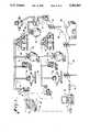
- FIG. 2is a schematic diagram showing the circuitry for encoding the meter registers of FIG. 1;
- FIG. 3schematically shows the arrangement of the meter dial encoding mechanism used with the present invention
- FIG. 4is a more detailed schematic of the interface circuitry which forms part of the encoder circuitry shown in FIG. 2;
- FIG. 5is a diagram showing the relationship of the reader/programmer clock signal and biphase data signal of the encoder circuitry of FIG. 2;
- FIG. 6is a diagram showing the relationship of the reader/programmer clock signal and its demodulated data signal
- FIG. 7is a diagram illustrating the pulse-length data encoding scheme employed by the present invention.
- FIG. 8is a schematic diagram showing the general components making up the reader/programmer of the present invention.
- FIGS. 9A and 9B togetherare a more detailed schematic diagram of the two wire I/O circuitry shown in FIG. 8;
- FIG. 10is a side plan view showing the two wire inductive probe/adaptor and port as used with the present invention.
- FIGS. 11A and 11B togetherare a more detailed schematic diagram of additional circuitry comprising the reader/programmer shown in FIG. 8.
- FIG. 1shows the general configuration of a two and three wire utility data communication system constructed in accordance with the principles of the present invention.
- the systemcomprises a reader/programmer 1 having a connector 3 which is adapted to be connected directly to a three wire receptacle 5 or a two wire port 7 (when used with adaptor 9 disposed between connector 3 and port 7).
- Reader/programmer 1includes a display 11 and a rechargeable battery pack or power source 13. Reader/programmer 1 may further include a data storage memory, a microprocessor and input/output circuits as described in more detail below with respect to FIG. 8. Reader/programmer 1 may further include a recharging and data transfer connector 15 which is adapted to mate with a recharging cradle/data transfer unit 17, as shown in FIG. 1. Recharger/data transfer cradle 17 is connected to a computer 19, such as an IBMTM compatible personal computer, or the like, via a standard RS232 serial interface. The computer 19 may further include an internal or external modem 21 for transferring data over telephone lines 23 back to a utility's home office 25 for billing or load survey purposes.
- a computer 19such as an IBMTM compatible personal computer, or the like
- Reader/programmer 1is designed to be portable and to be carried around by a meter reader as he makes his rounds to read meters along a predesignated route.
- reader/programmer 1may be preprogrammed, preferably when connected to computer 19 via recharger/data transfer unit 17, to load routing information into a memory contained within reader/programmer 1.
- This routing informationwhich may be called up by the meter reader is displayed on display 11.
- This routing informationtells the meter reader where the next meter to be read is located, and may also indicate the meter type (e.g. water, gas or electric), the meter serial number, and the last meter reading for that particular location.
- an encoderis associated with the meter register with the encoder having a series of conductive pads and a moveable contact associated with one or more odometer- type register display wheels.
- the position of the moveable contact with respect to the conductive padsindicates the register wheel position and hence the quantity being displayed by the meter register.
- the registered position informationis transmitted via three or fourteen conductive wires to the reader/programmer. Data is transmitted from the encoder to the remote reader.
- a second type of systemutilizes an encoded meter register connected to a two wire port which, in turn, is inductively coupled to a portable meter reading device.
- a portable meter reading unitis provided with an inductive loop or coil which mates with a similar loop or coil arranged on a receptacle.
- the receptacleis coupled via two lines to an encoded meter register.
- the coil of the reading unitis brought into proximity with the coil of the receptacle and an AC interrogation signal is applied to the coil connected to the meter.
- This AC signalis transmitted to the remote meter register by means of the inductive coupling between the two coils.
- This interrogation signalis used to "wake up" the encoded meter register which sends back the meter reading data by modulating an AC carrier signal.
- the AC carrier signalcan be generated internally by the meter encoder or may be the interrogation signal itself.
- the present inventionenables a portable reader/programmer 1, such as shown in FIG. 1, to interrogate and read encoded water, gas, and electric meters over both three wire direct, electrical connections and two wire inductively coupled connections.
- the systemis also designed to be self-powered, that is to be powered solely by the power source 13 contained by the portable reader/programmer 1.
- the systemis also designed to remotely read more than one encoded meter register at a time, so that multiple encoded registers may be connected to a common two or three wire bus.
- Each of these encoded registersis responsive to interrogation signals generated by reader/programmer 1 to transmit back via bus 27 their register readings.
- the interrogation signal generated by reader/programmer 1is transmitted via adaptor 9, which includes an inductive loop or coil (shown in more detail in FIG. 10) which, when placed in proximity to port 7 induces an interrogation signal over two wire bus 43.
- Inductive port 7includes a complementary loop or coil to complete the inductive coupling with adaptor 9.
- encoded water meter 45Connected to two wire bus 43 are encoded water meter 45, encoded electric meter 47, encoded gas meter 49 and encoded compound meter 51.
- Each of these metersincludes an encoded meter register whose characteristics and circuitry are described in more detail below with respect to FIGS. 2, 3, and 4.
- FIG. 1the number and types of meters and registers shown in FIG. 1 are merely illustrative. Additional meters and registers of other types can be easily accommodated by the present invention.
- FIG. 1is the ability of reader/programmer 1 to read multiple remote encoded registers over a single two or three wire bus. This capability also enables reader/programmer 1 to read so-called "compound" meters, such as compound meters 35 and 51.
- a compound meteris a type of water meter which has a first register associated with a low flow measuring element and a second register associated with a high flow measuring element. Both registers must be read in order to obtain an accurate reading of water consumption.
- Another advantage of the present inventionis that the encoded registers, which are described in more detail below, can be used or interchanged with existing two or three wire remote meter reading equipment. This means that a customer does not have to concerned about making a choice between either a two or three- wire system and can select whichever one is suitable for his purposes while maintaining compatibility.
- Reader/programmer 1is specifically designed to be able to read encoded registers in either a two wire or a three wire system.
- a meter interface unit (MIU) 37may also be connected over a three wire bus 53 to encoded meter registers of the type described below with respect to FIGS. 2, 3, and 4.
- MIU 37preferably of the type as shown in U.S. Pat. No. 4,852,152.
- MIU 37may include up to four data ports for connection to up to four encoded registers or other data generating devices.
- FIG. 1shows an additional encoded water meter 39, encoded electric meter 41, and encoded gas meter 42 connected to the inputs of MIU 37 over three wire lines 53.
- MIU 37periodically interrogates encoded registers associated with meters 39 and 41 and stores signals indicative of the measured quantities in a memory provided in MIU 37.
- the data stored in the memory in MIU 37is responsive to an interrogation signal initiated at the utility home office 25 or by personal computer 19 to send the register readings from meters 39, 41, and 42 stored in the memory of MIU 37 over phone lines 55 or 23 to utility office 25 or computer 19.
- data indicative of the quantity of a commodity being measured by meters 39, 41, or 42may be transmitted back to a utility's central office 25 or to a computer 19.
- the encoder of the present inventionis directly usable with conventional meter interface units of the type described in U.S. Pat. No. 4,852,152 which require a three wire metallic connection, while also offering the possibility of being remotely read by means of a portable reader/programmer in either a two or three wire mode.
- FIG. 2shows the electronic components comprising an encoder register.
- FIG. 3shows how these components are connected to one or more odometer-type register wheels 56.
- a series of conductive pads 57 and a moveable contact 59are associated with each wheel of the odometer-type display. See U.S. Pat. No. 4,085,287 and U.S. patent application Ser. No. 433, 864, filed Nov. 9, 1989 for a more complete description of the mechanical aspects of the odometer-type wheel encoding mechanism.
- FIG. 3shows only four register wheels are shown schematically in FIG. 3, it is to be understood that the encoder arrangement shown in FIG. 2 can be easily adapted to handle any number of register wheels or display positions.
- a microprocessor unit U1has a number of switched inputs (typically ten in number) labelled W1, W2 . . . W0, which are connected to the corresponding conductive pads 57 associated with each odometer display wheel, as shown schematically in FIG. 3.
- Microprocessor unit U1further includes a series of switched outputs, S1, S2 . . . S6 which are connected to corresponding moveable contacts 59 associated with each register display wheel.
- wheel select outputs S1-S6are sequentially strobed and any switch closures detected through switch inputs W1, W2 . . . W0, which are indicative of the position of a particular register display wheel, are noted by microprocessor unit U1.
- Microprocessor unit U1preferably is of the S6 family manufactured by SGS Thompson.
- Microprocessor unit U1includes approximately 32 bytes of electrically erasable programmable read only memory (EEPROM) which can contain data characterizing the particular encoder register with which it is associated.
- EEPROMelectrically erasable programmable read only memory
- Microprocessor unit U1includes an optional switched input 61.
- Switched input 61for example, is a reed switch placed in proximity to the driving magnet associated with a water meter or the like. As the measuring element of the water meter rotates, the driving magnet will periodically move past the reed switch, causing it to close. This closure is detected by switched input 61 for use in measuring flow rates or instantaneous consumption, as described in more detail below.
- Microprocessor unit U1is connected to an interface unit U2 as shown in FIG. 2.
- Interface unit U2includes a voltage regulator, modulator and interface circuitry.
- Interface unit U2is derived from the bipolar family manufactured by SGS Thompson.
- interface unit U2The internal circuitry of interface unit U2 is shown in more detail in FIG. 4.
- Power for interface unit U2 and microprocessor unit U1is derived from an external source, e.g. interrogation signals applied by reader/programmer 1 or MIU 37 (see FIG. 1) to inputs IN1 and IN2 of interface unit U2.
- An interrogation signal(or programming signal as described below) applied to inputs IN1 and IN2 is used to power interface unit U2 and microprocessor unit U1 via a power supply bridge composed of diodes D1-D4 and voltage regulator 63.
- diode bridge D1-D4 and voltage regulator 63produces a regulated output voltage, V out , of approximately 4.45 volts which is applied from pin 3 of interface unit U2 to pin 19 of microprocessor unit U1.
- a power supply filter capacitor C2is tied between V out and ground GND as shown in FIG. 2.
- a further power supply filter capacitor C extis connected between ground GND and pin 11 of interface U2 which is connected to the input of voltage regulator 63.
- interface unit U2contains circuitry to modulate the amount of current consumed by the encoded register when in the two wire mode and an interface circuit which has an open collector for producing an output data signal when in the three wire mode.
- an interrogation signalhas a frequency of approximately 19.2 kHz.
- a portion of this signalis rectified by diode bridge D1-D4 and used to power microprocessor unit U1, as described above.
- U2includes a reset circuit which detects V out and will hold the microprocessor in a reset mode until V out has gone to a level which will guarantee that the microprocessor will operate properly. This prevents any false resets of the microprocessor or erroneous data from being output because of a lack of proper power.
- a Schmidt trigger 65is also connected to input IN1.
- Schmidt trigger 65is used to clean up the clock signal which supplies the clocking from the microprocessor so that the circuit can operate in a synchronous mode where the output rate is determined by the input clock signal.
- Transistor Q1has its collector tied to input IN2, its emitter tied to ground and its base tied, via current limiting resistor R1, to data line DATA2 connected to microprocessor U2.
- input IN2looks like an open collector to the circuit and during reading a resistor in the reader/programmer would act to pull-up the signal level for Q1 appearing at IN2.
- input IN1would supply the clock signal.
- interrogation or programming signalsapplied to IN1 and IN2 which are connected to diodes D5 and D6, respectively, which in turn are tied to the collectors of a transistor pair Q2.
- the emitters of transistor pair Q2are tied to ground through an external resistor Rext.
- the base of one of the transistor pair Q2is connected via buffer 67 to data line DATAL connected to microprocessor U1.
- the value of Rextdetermines the amount of additional current drawn, i.e. the amount of modulation when in the two wire mode.
- a 19.2 kHz square wave signalis applied across inputs IN1 and IN2 of interface unit U2.
- This interrogation signalmay be generated by reader/programmer 1 or MIU 37, as shown in FIG. 1.
- this interrogation signalis used to supply power to microprocessor unit U1 which then "wakes up”, checks the status of wheel bank inputs W1-W0 by strobing select wheel lines S1-S6.
- This wheel position informationwhich is indicative of the reading displayed by a particular odometer-type wheel, is then formatted and output by microprocessor unit U1 as a synchronous series of biphase logic signals, as shown in FIG. 5. For example, a logical "1" is indicated by no phase or state transition during 16 input clock cycles.
- a logical "0"is indicated by a transition occurring sometime during a sustained clock cycle.
- the phase or state transition shown in FIG. 5is indicative of a change in the impedance displayed across inputs IN1 and IN2 due to the action of transistor Q2 and the current modulation reference resistor Rext. Therefore, the biphase current modulation scheme as used in the two wire implementation of the present invention causes the amount of current being drawn by interface unit U2 to remain constant over 16 clock cycles to indicate that a logical one is being transmitted. The amount of current being drawn at inputs IN1 and IN2 will appear steady during a 16 clock cycle period.
- the "low” modulation levelis approximately 1 milliamp and the "high” level is 3 milliamps.
- the bi-phase encoded datais transmitted from inputs IN1 and IN2 back along the two wire bus 43 typically in a standard ASCII format as shown in FIG. 6. This format typically includes a start bit, 7 bits of data, with the least significant bit being transmitted first, a parity bit followed by two stop bits. Once a set of data has been transmitted, if the clock signals are still present, register wheel position information will be read again by microprocessor unit U1 and output again. This will be repeated as long as the clock signal is applied to inputs IN1 and IN2.
- microprocessor unit U1Each time that the data is clocked out of microprocessor unit U1, the status of the reed switch 61 is checked to see if the switch has opened and closed. If it has, it will increment a single digit counter in microprocessor unit U1 which can be included in the output data stream to show that flow through a meter, such as water meter 45, is occurring. If no flow is occurring, this flow status data bit will remain a 0.
- a clock signal having a frequency of, for example, 2400 Hzis applied between IN1 and ground.
- power for interface unit U2 and microprocessor unit U1is derived from the clock signal.
- Register wheel position datais gathered by microprocessor unit U1 and is output synchronously with the clock signal as an ASCII data stream through the action of transistor Q1 which appears as an open collector output.
- the ASCII data formatis the same as in the two wire mode, shown in FIG. 6.
- the speed with which data is output at terminal IN2is determined by the input clock frequency. Normally, this is a one-to-one ratio. However, it is possible to have data bits clocked out only after a predetermined number of clock cycles have occurred. Thus, if a divide by 16 relationship were used, one data bit would be output at terminal IN2 for every 16 clock cycles input at terminal IN1. This division ratio is programmable within microprocessor U1.
- the EEPROM which is part of microprocessor unit U1may be programmed as described in more detail below to contain data indicative of the characteristics of the encoded register with which it is associated.
- This characterization datamay include, among other things, a meter ID number or serial number, a "register select" number (described in more detail below), an ID or character indicative of the manufacturer of the meter, a character indicative of the type of meter, e.g. gas, water, or electric, a character indicative of whether the meter is to transmit in a two wire or three wire mode, and data indicative of the presence of a further meter register.
- the data indicative of the presence of a further meter registeris used in the case where two meter registers are to be read in tandem with each other, such as is the case with compound water meters.
- This datawill then indicate to a reader/ programmer the presence of the second register of the compound meter so that when the first register is interrogated by a reader/programmer, such as reader/programmer 1 shown in FIG. 1, the reader/programmer is alerted to the fact that there is a second register to be read, thus causing the reader/programmer to read the second register after reading the first register.
- All of the data stored in the EEPROM contained in microprocessor unit U1may be altered through the use of a suitable external programming signal, as described in more detail below.
- An important aspect of the present inventionis the capability of the meter reading system to read multiple encoded meter registers connected along a common two wire or three wire bus.
- reader/programmer 1 or MIU 37would have stored within their respective memories a listing of meter ID or serial number of every meter connected to the network.
- reader/programmer IWhen connected to the appropriate two wire or three wire network reader/programmer I would sequentially poll the meter IDs or serial numbers contained in its memory until all encoded meter registers on the network having those IDs or serial numbers had responded back.
- reader/programmer 1must contain a listing of all possible encoded registers which may be accessed on a particular route.
- reader/programmer 1would only have to cycle through register select numbers 00-99 in order to ensure that all encoded registers within that particular network were read.
- This special encoded registermay be assigned a unique or readily identifiable register select number such as "00" or "99". Reader/programmer 1 is then programmed to automatically check for this unique register select number. As part of the data stream coming back from this encoded register, the reader/programmer is then informed of the total number or highest register select number of the encoded registers connected to the local network.
- This arrangementenables reader/programmer 1 to rapidly and completely poll all encoded registers, and only those registers, connected to a particular local network without the waste of time of polling through unused register select numbers.
- the register select numberis transmitted from reader/programmer 1 over two wire network 43 or three wire network 27 as an eight bit number (two hexadecimal characters).
- the register select datais encoded by a type of pulse-length encoding in which 1s and 0s are indicated by periodically interrupting the clock signal (CLK) transmitted from reader/programmer 1.
- the clock signal (CLK)may be interrupted for approximately 1 millisecond every so many clock cycles. In the scheme employed by the present invention, and illustrated in FIG. 7, if the number of clock cycles between interruptions is less than 106, microprocessor unit U1 of the encoded register will interpret this as a logical "0".
- microprocessor unit U1interprets this as a logical "1". If the number of clock cycles between interruptions is greater than 138, microprocessor unit U1 interprets this as a reset period, that is, a buffer area within microprocessor U1 which is looking for the incoming register select data bits is automatically reset if there is more than 138 clock cycles between interruptions.
- the pulse-length encoding schemeutilizes one millisecond gaps in the 19.2 kHz interrogation or data signal to indicate separations between data bits.
- a logical "1"is represented by a 7 millisecond pulse train of the 19.2 kHz clock burst.
- a logical "0"is represented by a 4 millisecond pulse train of the 19.2 kHz clock.
- Data in the program or query modesis sent using even parity ASCII.
- an important feature of the present inventionis the ability to reprogram the EEPROM contained in the microprocessor unit U1.
- the contents of the EEPROMmay be overwritten or changed.
- the contents of the EEPROMmay be read out but not changed.
- the program modegives a customer the ability to customize the characteristics identified with a particular encoded register.
- the query modeallows the customer to check the contents of the EEPROM to ensure that the contents of the EEPROM have been properly written.
- reader/programmer 1In order to place the encoded register into to the query or program mode, reader/programmer 1 generates a special 38.4 kHz interrogation signal. This signal is exactly twice the frequency of the normal interrogation signal frequency of 19.2 kHz. This special query/program signal lasts for a minimum of 50 milliseconds.
- Microprocessor unit U1 of the encoded registeris programmed having a timing loop which detects the frequency of the incoming clock signal. If the frequency is 19.2 kHz, the microprocessor assumes the normal interrogation mode, reads the position of the various register display wheels, and reports back to the reader/programmer 1 as previously described.
- microprocessor unit U1If the microprocessor unit U1 detects the 38.4 kHz query/program mode interrogation signal, it will then enter into the query/program mode. microprocessor unit U1 then looks for a unique ASCII character transmitted by reader/programmer 1. Reader/programmer 1 sends a Q in order to query the contents of the EEPROM over a two wire network. A q is sent by reader/programmer 1 in order to query the contents of the EEPROM over a three wire network. Upon receipt of either the Q or q character, microprocessor unit U1 then transmits out the contents of the EEPROM as even parity ASCII data.
- a Pis sent by reader/programmer 1 when used in conjunction with a two wire network, and a p is sent when used in conjunction with a three wire network.
- P or p32 data bytes of program information is sent to microprocessor unit U1. Since microprocessor unit U1 has been placed in the programming mode, it then allows the contents of the EEPROM to be overwritten with this new program data.
- microprocessor unit U1immediately reads out the new contents of the EEPROM, as if it were in the query mode, back to reader/programmer 1 for confirmation of the data programmed into the EEPROM.
- the microprocessor unit U1Upon the completion of either a query or program mode interrogation of the encoded register, the microprocessor unit U1 automatically reverts back to its normal interrogation mode. In this mode, data from the encoded register is transmitted back as 23 to 34 bytes of data depending upon the meter reading and ID sizes.
- a typical data message formatis shown in the following Table 1:
- the messagebegins with an STX character (data blocks are separated by ETB characters), and the message ends with an ETX character.
- the flow charactercan be a character from 0-9. In case the flow rate function is not implemented, this character will be a space.
- the three "user characters"do not affect the operation of the register but allows the end customer to put in identifying characters or information in the register.
- the two character checksumis normally the summation of all the data characters contained in the data message, excluding the STX and ETX characters. However, if desirable, in the program mode a checksum character may be sent to the EEPROM contained as part of microprocessor unit U1 which will also identify which characters in the data message are derived from the contents of the EEPROM itself and the meter reading.
- Microprocessor unit U1will then add the flow data, (if implemented) and meter reading to this checksum character. This saves on the time it takes microprocessor unit U1 to process the information since it only has to add the additional flow and meter reading data to the already existing checksum and not do a total recalculation of the checksum. In addition, it provides backup verification that the information contained in the EEPROM of microprocessor unit U1 has not been altered. If such alteration should occur, either accidentally or deliberately, the checksum would be incorrect and an error message would be transmitted back to reader/programmer 1.
- a 19.2 kHz interrogation (clock) signalis generated by reader/programmer 1 and sent over the two wire or three wire network to an encoded register.
- Poweris derived from this interrogation signal by interface unit U2 of the encoded register and used to "wake up" microprocessor unit U1.
- Microprocessor unit U1times the interrogation clock pulses to confirm that a true interrogation signal is present, not noise or other transients.
- Microprocessor unit U1then strobes select wheel lines S1-S6 and detects the presence of signals along wheel bank lines W1-W0. This information is then stored in a temporary scratch pad memory contained in microprocessor unit U1.
- microprocessor unit U1will reread the positions of the register display wheel up to five times and compare the current reading with the just preceding reading until a validated match is found. If no match occurs after five readings, microprocessor unit U1 will fill the meter reading data field (see Table 1) with the character X, instead of the numeric characters 0-9. In addition, microprocessor unit U1 looks for shorted and open contacts, e.g.
- reed switch 61For flow and leak detection, the status of reed switch 61 is monitored any time microprocessor unit U1 is powered up. The status of reed switch 61 is affected by the rotation of the magnetic drive coupling magnet which is part of a standard water flow meter. The rotation of the magnet, and hence the opening and closing of reed switch 61, represents the flow of fluid through the meter.
- the rate of magnet rotation, and hence the number of openings and closings of reed switch 61 per unit time,represents the rate of flow.
- the status of reed switch 61is monitored to determine whether an opening or closing of reed switch 61 has occurred. Thus, if the status of reed switch 61 has changed during interrogation of the encoded register, this fact will be noted by microprocessor unit U1 and the flow character which is part of the data message (see Table 1) will be output to indicate that flow is occurring.
- leaksmay be detected by first shutting off all normal sources of water use at a premises (e.g. washing machines, dishwashers, sinks, and tubs). The encoded register is interrogated by reader/programmer 1 for a few seconds to see whether flow is occurring (i.e. if the status of reed switch 61 changes). Of course, the leak detection mode only informs a user that flow is occurring, but gives no information about the rate of flow.
- the reed switch 61is monitored for several seconds, or a longer period if desired.
- the number of openings and closings of reed switch 61is counted and temporarily stored in scratch pad memory of microprocessor unit U1.
- the number of openings and closings over the monitoring period(whose time interval is measured by timing circuitry contained within microprocessor unit U1) is used to calculate the flow rate. This is readily done since the opening and closing of reed switch 61 indicates one-half revolution by the magnetic coupling of its associated water meter. The volume of water passing through the meter per one revolution is a known quantity.
- the flow rateis then simply calculated using the formula: ##EQU1##
- microprocessor unit U1It is also possible to program microprocessor unit U1 so that immediately after reading out the position of each of the register display wheels, microprocessor unit U1 then goes into a flow rate detection mode for a predetermined period of time. This obviates the need to separately query the encoded register to begin flow rate detection after entering the interrogation mode.
- the flow rate detection schememay be utilized to provide a so-called "pulser" output.
- the encoded registere.g. 39 in FIG. 1
- MIU 37is either self-powered (using an internal battery), or more typically, powered by the voltage normally present on telephone lines 55. MIU 37 may then continuously or intermittently monitor the status of the flow character output by the microprocessor unit U1 associated with the encoded meter register. Since the volume of water or other available commodity per revolution of the magnetic coupling of meter 39 is a known quantity, the number of pulses received by MIU 37 from encoded meter register 39 over time is indicative of the total quantity of water or other billable commodity measured by the metering mechanism.
- an electricity metermay include a pulser output where rotation of the meter's eddy disk is detected by electro-optical means.
- Other sources of pulses or status informationsuch as piezoelectrically driven pulse generators, electromotive generators, or the like may be used with suitable pulse or status detection circuitry which is well known in the art.
- an important feature of the described meter reading systemis its ability to poll or read multiple encoded meter registers connected to the same local two wire or three wire network.
- reader/programmer 1would send a "register select" number which, for example, could be a number between 00-99.
- Each encoded meter register connected to a particular local networkwould have previously been programmed (e.g. using the "program” mode function described above) with a register select number unique to that particular network.
- the encoded meter registers, in particular the microprocessor unit U1 associated with each registeris programmed to recognize its register select number, which was previously programmed and stored within the EEPROM associated with the particular microprocessor unit U1.
- the registerupon recognizing its register select number, would then take a reading of the register display wheels and respond with this reading, along with the other data associated with a meter reading message, as set forth in Table 1.
- the two bytes of information set aside for "network ID”, as set forth in Table 1are the same as the "register select number”.
- the reader/programmer 1In a basic polling mode, the reader/programmer 1 would send out a register select number of 01, followed by 02, etc. until it had cycled through all possible register select numbers. Responses will be heard back from any encoded registers whose register select number is interrogated. In this way, reader/programmer 1 does not have to know the serial number or unique ID of a particular encoded meter register, but need only cycle through all possible register select numbers in order to ensure polling of all encoded registers on a particular network. If a two byte register select number is used, this will accommodate up to 100 encoded registers on a single local network (register select numbers 00-99).
- register select numbersallows a more sophisticated polling technique than the foregoing to be used.
- reader/programmer 1can be preprogrammed to always poll for register select number "99" as its first register select number.
- One of the encoded meter registers on a particular local networkis preprogrammed to respond to this "99" register select number.
- This registerwould not respond back with the "99" register select number, but rather with a number which is equal to the number of registers attached to the particular local network. For example, if there were four registers connected to the local network, this register would reply back with a register select number of "4" which would tell the reader/programmer that there were three additional registers.
- These additional registerswould have been previously programmed with register select numbers 01, 02 and 03.
- the reader/programmer 1would then poll these three additional registers in any order. Thus, upon initially interrogating a local network, the reader/programmer 1 will immediately know how many encoded meter registers are connected to that particular network and will not waste time cycling through register select numbers which are not present on the network.
- the first encoded register of the compound metercan be assigned a unique register select number, e.g. "99". This would tell reader/programmer 1 that the meter is a compound meter and to look for a reading from the second encoded register associated with the compound meter.
- This second encoded registercan be assigned an unique register select number of "01".
- the choice of the particular register select numbers mentioned aboveare purely arbitrary and can be easily changed to suit a particular user.
- Reader/programmer 1comprises a microprocessor 64, preferably a Z8 processor manufactured by Zilog.
- Microprocessor 64includes scratch pad memories, buffer memories, a clock, and input/output (I/O) circuitry for interfacing with external devices. The details of construction and operation of such a microprocessor is well-known and will not be described in any further detail here.
- a random access memory 65is associated with microprocessor 64 for temporarily storing instructions or data processed by microprocessor 64.
- Microprocessor 64also communicates with two wire input/output circuitry 67 and three wire/fourteen wire input/output circuitry 69, which are described in more detail below.
- a buzzer or other audible alarm sounding device 71is connected to microprocessor 64 to sound an audible alarm under certain conditions.
- a keypad 73is connected to microprocessor 64. Keypad 73 allows data or other information to be manually entered directly into microprocessor 64.
- a display 75which corresponds generally to display 11 as shown in FIG. 1, is also connected to microprocessor 64 for visually displaying data or other information being processed or stored by microprocessor 64.
- Reader/programmer 1may further include an RS232 (serial) input/output interface 77 which enables microprocessor 64 to be externally programmed and/or the contents of RAM 65 to be read out or altered via the output connector port 15 shown in FIG. 1.
- Reader/programmer 1includes a battery 79 which corresponds generally to power source 13 shown in FIG. 1.
- Battery 79is preferably of the rechargeable nickel-cadmium type which supplies DC power to microprocessor 64, two wire I/O circuit 67, three wire/fourteen wire I/O circuit 69 and other related circuitry of reader/programmer 1.
- microprocessor 64may include a function whereby the output voltage of battery 79 is monitored and an alarm, e.g. buzzer 71 and/or display 75, is activated if the output voltage of battery 79 should fall below a predetermined level, indicating a need for recharging.
- the watchdog timerwhich is included as part of microprocessor 64 may be set to remove power from most of the circuitry comprising reader/programmer 1 in the event power is left on but no activity is detected. This helps to save the energy stored in battery 79 in the event reader/programmer 1 is accidentally left on. In the event power is thus removed, only a minimal amount of current will be drawn from battery 79 sufficient to keep certain vital functions running e.g. the contents of RAM 65 and the clock and switched inputs to microprocessor 64.
- Two wire I/O circuitry 67includes a driver power supply circuit, a coil drive circuit, a demodulator circuit, miscellaneous logic circuitry, two wire I/O power supply circuitry, all as shown in more detail in FIG. 9. Both the coil drive circuitry and demodulator circuitry are coupled to drive coil 83.
- drive coil 83is formed as part of probe/adaptor 9, as shown in FIG. 1 and in more detail in FIG. 10.
- Drive coil 83is formed as multi-turn loop of wire disposed at the end of probe/adaptor 9.
- a sensor switch 85is located proximate drive coil 83.
- Sensor switch 85is a normally-open mechanical silicone rubber switch with a conductive pad on the bottom. Sensor switch 85 is fully weather-sealed from the environment.
- the opposite end of probe/adaptor 9contains four connectors, two of which are connected to drive coil 83 and two which are connected to sensor switch 85. These connectors in turn mate with connectors which comprise connector 3 of reader/programmer 1 (see FIG. 1).
- Connector 3 of reader/programmer 1includes pin-type connectors for connecting to probe/adaptor 9, three wire receptacle 5 or a 14 pin receptacle (not shown) which is still employed on some older types of prior-art encoded meter registers.
- switch 85indicates to the two wire I/O circuitry 67 that probe/adaptor 9 is in contact with two wire port 7.
- Two wire port 7is comprised of one or more turns of wiring.
- reader/programmer 1may further include a manual trigger 87 (see FIGS. 1 and 8) which is a normally-open switch that can be used to manually activate the two wire or three/fourteen wire I/O circuits 67 and 69 and microprocessor 64.
- Manual triggering of reader/programmer 1can be used to override the touch sensitive triggering provided by sensor switch 85 when it is desired to manually activate reader/programmer 1.
- Manual triggering of reader/programmer 1also acts a backup in case the touch-sensitive switch 85 should fail for some reason.
- touch-sensitive automatic switching using sensor switch 85has been described primarily in connection with probe/adaptor 9 and two wire port 7, a touch-sensitive sensor switch of the same type could be employed in connection with port 3 of reader/programmer 1 to enable automatic activation of reader/programmer 1 when connecting to a hard-wired three or fourteen wire receptacle 5, as shown in FIG. 1.
- inductive coupling between reader/programmer 1 and 2 wire network 43is shown in FIG. 1, it should also be noted that the output of two wire I/O circuitry 67 need not be connected via drive coil 83 to inductive port 7. Instead, the lines normally connected to drive coil 83 could be connected directly, (either permanently or removably) to two wire local network 43. In the normal two wire mode, reader/programmer 1 and the circuitry associated with the remote encoded register operate in a balanced mode when coupled through drive coil 83 and inductive port 7. If inductive coupling is not used, it is possible to connect the reader/programmer 1 directly to the two wire network 43. It is also possible for microprocessor unit U1 (FIG. 2) to turn on transistor Q1 (FIG.
- two wire I/O circuitry 67includes power supply circuitry 89 for supplying various regulated voltages to the remainder of two wire I/O circuitry 67.
- Power supply circuit 89also provides a voltage reference, V2 used by other elements of two wire I/O circuitry 67.
- a driver power supply 91utilizes a switching regulator IC, U6, in combination with inductor L1 and diode D5 to form a step-up DC-to-DC convertor to produce an output DC voltage, Vdriver, for driving drive coil 83.
- Transistor Q1 of driver power supply 91is the switching element for the DC-to-DC convertor.
- Demodulator circuit 93includes an oscillator having a crystal time base generated by crystal XT1 in connection with timing circuit U1. The output of the oscillator is fed to a switch capacitor filter device U5 having a cutoff frequency of approximately 1500 Hz. The frequency of the time base generated by the oscillator is set at approximately 100 times the cutoff frequency of the switched-capacitor filter, i.e. 150 kHz.
- Demodulator circuit 93further includes a current sampling resistor R17. Current sampling resistor R17 is coupled to the coil drive circuitry 91 output, Vdriver, and drive coil 83.
- Changes in current applied to drive coil 83are impressed across current sampling resistor R17 and applied to the switched capacitor filter device U5 which filters out high frequency elements associated with the clocking/interrogation signals applied to drive coil 83 by driver power supply 91.
- these clocking/interrogation signalsmay be 19.2 kHz for normal interrogation mode signals and 38.4 kHz for the initial query/programming mode signals, as previously described. Generation of these signals is described in more detail below.
- the filtered output of switched-capacitor filter device U5is amplified and then applied to a Schmidt trigger which detects any low frequency variations in the current sampled by the current sampling resistor R17. These sampled current changes are converted to voltage changes which are then compared with a reference voltage V2 at the Schmidtt trigger.
- the output of the Schmidt triggerwhich is applied to a buffer device U2, is thus indicative of variations in the current drawn through drive coil 83 due to changes in impedance caused by biphase modulated signals being applied to the two wire local network 43 by the action of transistor pair Q2 of interface unit U2 of the encoded meter register circuitry (see FIGS. 2 and 4).
- Microprocessor 64utilizes a software phase-locked-loop algorithm in which the phase of data being derived from the current modulated signal by demodulator 93 is detected. This prevents any skew in the phases of the data being returned back from an encoded meter register from causing microprocessor 64 to not be able to accurately reconstruct the data.
- An additional feature of the inventionwhen operated in the two wire mode, is that the coil drive circuit 95 and drive power supply 91 can detect if additional current is being drawn through the local two wire network 43 due to additional wiring being incorporated into the network. Since an individual local network 43 is apt to have different lengths of wiring from others, the amount of current drawn by a particular network, due to the impedance of the wires and their natural reactance at the interrogation/clock frequency of 19.2 kHz will also vary. Without adaptive compensation, as provided by the present invention, longer wiring runs would cause higher voltages to be induced at coil drive 83 and, hence, inductive port 7. These higher induced voltages may exceed the voltages which may be safely applied to the encoded register circuitry shown in FIG. 2.
- the amount of current being drawn through drive coil 83is monitored and the drive signal is reduced when the amount of current drawn rises. This is accomplished through the provision of resistor R20 in the output of driver power supply 91. As additional current is drawn through R20 due to increasing reactance exhibited by local network 43, this will be reflected in an increased current drain supplied through resistor R20 which, in turn causes the voltage (approximately 15 volts) supplied through call driver circuit 91 to decrease to compensate for the reactance exhibited through local network 43.
- the encoded meter registeracts to vary the load or impedance connected to the two wire local network 43 and effectively modulates the current flowing through drive coil 83 in accordance with the biphase encoded ASCII data being applied to local network 43 and coupled to drive coil 83 via inductive port 7.
- Demodulator circuit 93is used to detect variations in current being drawn through drive coil 83 by sampling this current through current sampling resistor R17, filtering the sampled signal via switched capacitor filter U5 and comparing the demodulated signal with a reference signal through the use of a Schmidt trigger to produce a demodulated data signal whenever such a change is detected.
- the coil drive circuitry 95is responsive to a two wire clock signal derived from microprocessor 64 and a "two wire enable" signal which is used to initiate transmission of the two wire clock (interrogation) signals through a pair of gates U2.
- microprocessor 64When microprocessor 64 outputs a "two wire enable" signal along pin 6 (shown in FIG. 9), it places this enable line into a low state and allows the application of the approximately 15 volt output, of Vdriver, of driver power supply 91 to be applied to coil drive circuit 95 via current sampling resistor R17.
- the two wire enable signalis also coupled to timing generator U1 of demodulator circuit 93 which, in turn, enables operation of the switched capacitor filter device U5.
- the two wire enable signaltherefore causes coil drive circuitry 95 to allow the passage of the 19.2 kHz clock/interrogation signal generated by microprocessor 64 to be applied to drive coil 83 and activates the demodulator circuit 93 to enable detection of any current-modulated signals being returned from an encoded register attached to local network 43.
- Two wire I/O circuit 67further includes some miscellaneous logic circuitry 97 which detect the status of the mechanical sensor switch 85 formed as part of the probe/adaptor 9. Circuitry 97 is also responsive to the actuation of manual trigger 87. Activation of trigger 87 may be used to cause reader/programmer unit 1 to display certain information when initially powered up, such as a unique ID or serial number for the reader/programmer 1, and any software revision numbers. When used in a polling mode, trigger 87 may be used to switch visual display 75 between one or two registers.
- FIG. 11shows in more detail the arrangement of circuitry comprising microprocessor 64.
- Microprocessor 64(also labelled U1 Z8 in FIG. 11) is an 8 bit processor and has approximately 8,000 bits of onboard EEPROM memory available. Of course, if additional memory is required, it can be supplied in the form of RAM memory 65 or an auxiliary PROM or EEPROM for handling operating instructions.
- Circuitry 99is power supply circuitry associated with microprocessor 64. Circuitry 101 is for negative voltage generation (U3) and display compensation (Q2) for display 75.
- U3negative voltage generation
- Q2display compensation
- Buzzer circuit 71is comprised of a single transistor (Q1) which is actuated whenever a "buzzer enable" signal is output from microprocessor 64. This buzzer signal may be enabled whenever an alarm condition is detected by microprocessor 64, for example, the detection of a tamper indication signal from an encoded meter register, a low battery warning, an ambiguous meter register reading, etc.
- buzzer circuit 71may also be used to indicate to the operator of reader/programmer 1 that a particular meter reading has been taken and it contains no errors.
- microprocessor 64includes a software "watchdog" timer which monitors various functions of reader/programmer 1 and disables reader/programmer 1 in the event certain conditions arise. For example, upon initial power up, due to closure of sensor switch 85, microprocessor 64 will generate clock/interrogation signals which are applied to drive coil 83. If no data is detected from local network 43 after a predetermined period of time, the watchdog timer will cause the clock/interrogation signal to be turned off. This function can also be programmed so as to automatically turn the clock/interrogation signal on a second time, after temporarily turning it off, in the event the initial state of reader/programmer 1 or a remote meter register is awakened in an ambiguous state.
- FIGS. 9 and 11can also be adapted to read encoded meter registers over a three wire network, such as local network 27 shown in FIG. 1, or a fourteen wire network as shown in U.S. Pat. No. 4,085,287.
- microprocessor 64can be arranged to have ten switched inputs connected to conductive pads 57 (see FIG. 3) of the individual register display wheels, and four inputs connected to the four movable contacts 59 (for a four wheel register display). By strobing these four contacts, the status of each of the ten switch position lines (e.g. lines 1, 2 . . . 0 in FIG.
- microprocessor 64can determine the position of an individual display wheel.
- fourteen wire encoded registersmay be read by implementing the reading circuitry described in U.S. Pat. No. 4,085,287 or the circuitry shown in FIG. 2.
- This circuitrycan be incorporated as part of the three wire/fourteen wire I/O circuitry 69 shown in FIG. 8.
- Three wire communicationsare implemented by reader/programmer 1 by the application of a clock signal, either derived from the two wire clock signal applied to coil drive circuit 95, or a separate clock generated directly by microprocessor 64. This signal is applied over the line labelled CLK in FIG. 8 and applied to input IN1 of interface circuitry U2 shown in FIG. 2.
- three wire data output from terminal IN2 of interface unit U2(FIG.
Landscapes
- Physics & Mathematics (AREA)
- General Physics & Mathematics (AREA)
- Engineering & Computer Science (AREA)
- Computer Networks & Wireless Communication (AREA)
- Arrangements For Transmission Of Measured Signals (AREA)
Abstract
Description
TABLE 1 ______________________________________ Standard ARB VI Data Format Number of Bytes Data Byte Description ______________________________________ 1 STX -- 1 1DATA Format Code 2 0-9 Network ID, High Byte -- 0-9 Network ID, Low Byte 1 S Manufacturer (e.g. Schlumberger) 1 W Type of meter (e.g. Water) 1 ETB -- 4 to 6Alphanumeric Meter Reading 1 ETB -- 1 to 10Numeric ID Number 1 ETB -- 1 0-9Flow Character 1 ETB -- 1Alphanumeric User Character 1 1Alphanumeric User Character 2 1Alphanumeric User Character 3 1 ETB -- 2Alphanumeric Checksum 1 EXT -- ______________________________________
Claims (27)
Priority Applications (1)
| Application Number | Priority Date | Filing Date | Title |
|---|---|---|---|
| US07/903,203US5252967A (en) | 1990-05-25 | 1992-06-23 | Reader/programmer for two and three wire utility data communications system |
Applications Claiming Priority (2)
| Application Number | Priority Date | Filing Date | Title |
|---|---|---|---|
| US07/528,391US5155481A (en) | 1990-05-25 | 1990-05-25 | Two and three wire utility data communications system |
| US07/903,203US5252967A (en) | 1990-05-25 | 1992-06-23 | Reader/programmer for two and three wire utility data communications system |
Related Parent Applications (1)
| Application Number | Title | Priority Date | Filing Date |
|---|---|---|---|
| US07/528,391DivisionUS5155481A (en) | 1990-05-25 | 1990-05-25 | Two and three wire utility data communications system |
Publications (1)
| Publication Number | Publication Date |
|---|---|
| US5252967Atrue US5252967A (en) | 1993-10-12 |
Family
ID=27062716
Family Applications (1)
| Application Number | Title | Priority Date | Filing Date |
|---|---|---|---|
| US07/903,203Expired - LifetimeUS5252967A (en) | 1990-05-25 | 1992-06-23 | Reader/programmer for two and three wire utility data communications system |
Country Status (1)
| Country | Link |
|---|---|
| US (1) | US5252967A (en) |
Cited By (119)
| Publication number | Priority date | Publication date | Assignee | Title |
|---|---|---|---|---|
| US5473540A (en)* | 1990-09-06 | 1995-12-05 | Delco Electronics Corp. | Electronic controller for vehicle |
| US5485150A (en)* | 1991-10-07 | 1996-01-16 | Yamatake-Honeywell Co., Ltd. | Remote data read system |
| US5487151A (en)* | 1991-04-15 | 1996-01-23 | Hochiki Kabushiki Kaisha | Transmission error detection system for use in a disaster prevention monitoring system |
| US5581229A (en)* | 1990-12-19 | 1996-12-03 | Hunt Technologies, Inc. | Communication system for a power distribution line |
| US5583493A (en)* | 1993-08-27 | 1996-12-10 | Pruftechnik Dieter Busch Ag | Process and apparatus for the remote polling of measuring points |
| US5590179A (en)* | 1993-02-12 | 1996-12-31 | Ekstrom Industries, Inc. | Remote automatic meter reading apparatus |
| US5594431A (en)* | 1992-03-19 | 1997-01-14 | Abb Kent Plc | Remote meter reading |
| US5612890A (en)* | 1995-05-19 | 1997-03-18 | F C Systems, Inc. | System and method for controlling product dispensation utilizing metered valve apparatus and electronic interconnection map corresponding to plumbing interconnections |
| US5619192A (en)* | 1994-06-14 | 1997-04-08 | Logicon, Inc. | Apparatus and method for reading utility meters |
| US5696501A (en)* | 1994-08-02 | 1997-12-09 | General Electric Company | Method and apparatus for performing the register functions for a plurality of metering devices at a common node |
| WO1998004095A1 (en)* | 1996-07-22 | 1998-01-29 | Nilsen Industrial Electronics Pty. Ltd. | Networking system |
| US5793754A (en)* | 1996-03-29 | 1998-08-11 | Eurotherm Controls, Inc. | Two-way, two-wire analog/digital communication system |
| US5815086A (en)* | 1994-10-20 | 1998-09-29 | Ies Technologies, Inc. | Automated appliance control system |
| US5818725A (en)* | 1993-08-11 | 1998-10-06 | First Pacific Networks | System for utility demand monitoring and control |
| US5918380A (en)* | 1997-09-17 | 1999-07-06 | Itron, Inc. | Time-of-use and demand metering in conditions of power outage |
| US6304191B1 (en) | 1999-03-30 | 2001-10-16 | American Meter Co. | Uni-directional protocol |
| US6333975B1 (en) | 1998-03-03 | 2001-12-25 | Itron, Inc. | Method and system for reading intelligent utility meters |
| US6346875B1 (en)* | 2000-01-03 | 2002-02-12 | General Electric Company | GHM aggregator |
| FR2817110A1 (en)* | 2000-11-17 | 2002-05-24 | Cahors App Elec | Domestic utility remote meter reading mechanism, having remote switch on mechanism sending measurement size and receivers receiving signal/converting bus with meter bus collecting digital words |
| US6424270B1 (en)* | 1998-10-30 | 2002-07-23 | Schlumberger Resource Management Services, Inc. | Utility meter interface unit |
| ES2170652A1 (en)* | 2000-04-07 | 2002-08-01 | Siemens Sa | GAS VOLUME CORRECTOR SYSTEM. |
| US20020145528A1 (en)* | 2001-01-22 | 2002-10-10 | If M Electronic Gmbh | Electrical transducer |
| US6512463B1 (en) | 1999-03-30 | 2003-01-28 | American Meter Co. | Bi-directional protocol |
| US20030043052A1 (en)* | 1994-10-24 | 2003-03-06 | Fisher-Rosemount Systems, Inc. | Apparatus for providing redundant wireless access to field devices in a distributed control system |
| US6611769B2 (en) | 2001-04-13 | 2003-08-26 | Badger Meter, Inc. | Meter register with programming and data port and meter input resolution factor |
| US6622097B2 (en) | 2001-06-28 | 2003-09-16 | Robert R. Hunter | Method and apparatus for reading and controlling electric power consumption |
| US20030179714A1 (en)* | 2002-03-21 | 2003-09-25 | Gilgenbach Alan M. | Meter monitoring and tamper protection system and method |
| WO2001082028A3 (en)* | 2000-04-25 | 2003-12-11 | Airak Inc | System and method for distributed monitoring using remote sensors |
| US6671636B2 (en) | 2000-11-20 | 2003-12-30 | Utility Collection Systems, Llc | Apparatus, method and article of manufacture for utility monitoring |
| US6700902B1 (en) | 1998-10-19 | 2004-03-02 | Elster Electricity, Llc | Method and system for improving wireless data packet delivery |
| US20040069345A1 (en)* | 2002-07-29 | 2004-04-15 | Doan Duc T. | Water supply system for multiple dwelling units |
| US20040078154A1 (en)* | 2001-06-28 | 2004-04-22 | Hunter Robert R. | Method and apparatus for reading and controlling utility consumption |
| US20040113812A1 (en)* | 2002-11-04 | 2004-06-17 | Tim Bianchi | Communications and features protocol for a measuring water meter |
| US6756914B1 (en) | 1999-11-12 | 2004-06-29 | Itron, Inc. | Low impedance encoder for a utility meter |
| US6867707B1 (en) | 2002-04-24 | 2005-03-15 | Elster Electricity, Llc | Automated on-site meter registration confirmation using a portable, wireless computing device |
| US20050062677A1 (en)* | 1999-02-12 | 2005-03-24 | Nixon Mark J. | Portable computer in a process control environment |
| US20050068749A1 (en)* | 2003-09-29 | 2005-03-31 | Funai Electric Co., Ltd. | Outer casing of electric equipment |
| US20050080610A1 (en)* | 2003-10-10 | 2005-04-14 | Synopsys, Inc. | Dynamic FIFO for simulation |
| US20050110656A1 (en)* | 1999-10-16 | 2005-05-26 | Tim Patterson | Automated meter reader having high product delivery rate alert generator |
| US20050164684A1 (en)* | 1999-02-12 | 2005-07-28 | Fisher-Rosemount Systems, Inc. | Wireless handheld communicator in a process control environment |
| ES2244258A1 (en)* | 2002-10-14 | 2005-12-01 | Contadores De Agua De Zaragoza, S.A. | Water container data system for obtaining data of different container groups to control water container system, generates warnings automatically after processing and analyzing obtained data from different groups of containers |
| US20060004587A1 (en)* | 2004-07-01 | 2006-01-05 | Willbanks C G Jr | System for distribution of hot and cold water and metering of same |
| US20060028355A1 (en)* | 1999-10-16 | 2006-02-09 | Tim Patterson | Automated meter reader having peak product delivery rate generator |
| US20060032533A1 (en)* | 2002-07-08 | 2006-02-16 | Fisher-Rosemount Systems, Inc. | System and method for automating or metering fluid recovered at a well |
| US7046682B2 (en) | 1997-02-12 | 2006-05-16 | Elster Electricity, Llc. | Network-enabled, extensible metering system |
| US7053767B2 (en) | 1998-06-22 | 2006-05-30 | Statsignal Systems, Inc. | System and method for monitoring and controlling remote devices |
| US7079810B2 (en) | 1997-02-14 | 2006-07-18 | Statsignal Ipc, Llc | System and method for communicating with a remote communication unit via the public switched telephone network (PSTN) |
| US7103511B2 (en) | 1998-10-14 | 2006-09-05 | Statsignal Ipc, Llc | Wireless communication networks for providing remote monitoring of devices |
| WO2006104580A2 (en) | 2005-03-24 | 2006-10-05 | M & Fc Holding, Llc | Method and apparatus with inductive coupling connector for connecting a water meter to a wireless data-communication device |
| US7119713B2 (en) | 2002-06-27 | 2006-10-10 | Elster Electricity, Llc | Dynamic self-configuring metering network |
| US7126494B2 (en) | 1997-02-12 | 2006-10-24 | Elster Electricity, Llc | Remote access to electronic meters using a TCP/IP protocol suite |
| US7136711B1 (en)* | 2002-11-21 | 2006-11-14 | Global Network Security, Inc. | Facilities management system |
| US7137550B1 (en) | 1997-02-14 | 2006-11-21 | Statsignal Ipc, Llc | Transmitter for accessing automated financial transaction machines |
| US7142106B2 (en) | 2004-06-15 | 2006-11-28 | Elster Electricity, Llc | System and method of visualizing network layout and performance characteristics in a wireless network |
| US7162730B1 (en) | 1998-01-07 | 2007-01-09 | Honeywell International, Inc. | Information communication systems |
| US7170425B2 (en) | 2004-09-24 | 2007-01-30 | Elster Electricity, Llc | System and method for creating multiple operating territories within a meter reading system |
| US7176807B2 (en) | 2004-09-24 | 2007-02-13 | Elster Electricity, Llc | System for automatically enforcing a demand reset in a fixed network of electricity meters |
| US7187906B2 (en) | 2004-04-26 | 2007-03-06 | Elster Electricity, Llc | Method and system for configurable qualification and registration in a fixed network automated meter reading system |
| US7209840B2 (en) | 2000-08-09 | 2007-04-24 | Hunt Technologies, Llc | Systems and methods for providing remote monitoring of electricity consumption for an electric meter |
| US7227350B2 (en) | 2004-03-18 | 2007-06-05 | Elster Electricity, Llc | Bias technique for electric utility meter |
| US7230582B1 (en) | 1999-02-12 | 2007-06-12 | Fisher-Rosemount Systems, Inc. | Wearable computer in a process control environment |
| US7239250B2 (en) | 2004-04-26 | 2007-07-03 | Elster Electricity, Llc | System and method for improved transmission of meter data |
| US7259690B1 (en)* | 1999-05-28 | 2007-08-21 | Mars Company | Reader for utility meter |
| US7263073B2 (en) | 1999-03-18 | 2007-08-28 | Statsignal Ipc, Llc | Systems and methods for enabling a mobile user to notify an automated monitoring system of an emergency situation |
| US7262709B2 (en) | 2004-04-26 | 2007-08-28 | Elster Electricity, Llc | System and method for efficient configuration in a fixed network automated meter reading system |
| US20070229306A1 (en)* | 2003-09-15 | 2007-10-04 | Jens Otterbach | Sensor |
| US20070258574A1 (en)* | 2003-11-06 | 2007-11-08 | Paraskevakos Theodore G | Remote Management of Products and Services |
| US7295128B2 (en) | 1998-06-22 | 2007-11-13 | Sipco, Llc | Smoke detection methods, devices, and systems |
| US7308370B2 (en) | 2005-03-22 | 2007-12-11 | Elster Electricity Llc | Using a fixed network wireless data collection system to improve utility responsiveness to power outages |
| US7308369B2 (en) | 2005-09-28 | 2007-12-11 | Elster Electricity Llc | Ensuring automatic season change demand resets in a mesh type network of telemetry devices |
| US7312721B2 (en) | 2002-06-28 | 2007-12-25 | Elster Electricity, Llc | Data collector for an automated meter reading system |
| US7315162B2 (en) | 2004-03-18 | 2008-01-01 | Elster Electricity, Llc | Reducing power consumption of electrical meters |
| US7327998B2 (en) | 2004-12-22 | 2008-02-05 | Elster Electricity, Llc | System and method of providing a geographic view of nodes in a wireless network |
| US20080052019A1 (en)* | 2006-08-25 | 2008-02-28 | Brennan W J | Compact Data Transmission Protocol for Electric Utility Meters |
| US7346463B2 (en) | 2001-08-09 | 2008-03-18 | Hunt Technologies, Llc | System for controlling electrically-powered devices in an electrical network |
| US7377184B1 (en)* | 2007-02-06 | 2008-05-27 | Schlachter Raymond W | Multipurpose centralized flow detector |
| US7397907B2 (en) | 1997-02-14 | 2008-07-08 | Sipco, Llc | Multi-function general purpose transceiver |
| US7424527B2 (en) | 2001-10-30 | 2008-09-09 | Sipco, Llc | System and method for transmitting pollution information over an integrated wireless network |
| US7427927B2 (en) | 2006-02-16 | 2008-09-23 | Elster Electricity, Llc | In-home display communicates with a fixed network meter reading system |
| US7460931B2 (en) | 2005-10-07 | 2008-12-02 | Jay Jacobson | Method and system for improving the efficiency and reliability of a power grid |
| US7480501B2 (en) | 2001-10-24 | 2009-01-20 | Statsignal Ipc, Llc | System and method for transmitting an emergency message over an integrated wireless network |
| US7495578B2 (en) | 2005-09-02 | 2009-02-24 | Elster Electricity, Llc | Multipurpose interface for an automated meter reading device |
| EP2042837A1 (en)* | 2007-09-26 | 2009-04-01 | Kamstrup A/S | Meter device for communicating on a communication line |
| US7545285B2 (en) | 2006-02-16 | 2009-06-09 | Elster Electricity, Llc | Load control unit in communication with a fixed network meter reading system |
| US7650425B2 (en) | 1999-03-18 | 2010-01-19 | Sipco, Llc | System and method for controlling communication between a host computer and communication devices associated with remote devices in an automated monitoring system |
| CN101635417A (en)* | 2008-07-21 | 2010-01-27 | 恩德莱斯和豪瑟尔测量及调节技术分析仪表两合公司 | Plug connector module |
| US7688220B2 (en) | 2005-12-16 | 2010-03-30 | Hunt Power, L.P. | Device and method for processing meter data from multiple meters |
| US7697492B2 (en) | 1998-06-22 | 2010-04-13 | Sipco, Llc | Systems and methods for monitoring and controlling remote devices |
| US7702594B2 (en) | 2004-09-24 | 2010-04-20 | Elster Electricity, Llc | System and method for automated configuration of meters |
| US7741976B2 (en) | 2005-12-16 | 2010-06-22 | Hunt Power, L.P. | Server and method for processing meter data into a common format |
| US7742430B2 (en) | 2004-09-24 | 2010-06-22 | Elster Electricity, Llc | System for automated management of spontaneous node migration in a distributed fixed wireless network |
| US7756086B2 (en) | 2004-03-03 | 2010-07-13 | Sipco, Llc | Method for communicating in dual-modes |
| US20100302061A1 (en)* | 2003-06-13 | 2010-12-02 | Arad Measuring Technologies Ltd. | Meter Register and Remote Meter Reader Utilizing a Stepper Motor |
| US8000314B2 (en) | 1996-12-06 | 2011-08-16 | Ipco, Llc | Wireless network system and method for providing same |
| US8031650B2 (en) | 2004-03-03 | 2011-10-04 | Sipco, Llc | System and method for monitoring remote devices with a dual-mode wireless communication protocol |
| US8064412B2 (en) | 1998-06-22 | 2011-11-22 | Sipco, Llc | Systems and methods for monitoring conditions |
| US8073384B2 (en) | 2006-12-14 | 2011-12-06 | Elster Electricity, Llc | Optimization of redundancy and throughput in an automated meter data collection system using a wireless network |
| US20120026006A1 (en)* | 2004-10-05 | 2012-02-02 | Electro Industries/Gauge Tech | Meter having a communication interface for receiving and interfacing with a communication device |
| US8203463B2 (en) | 2009-02-13 | 2012-06-19 | Elster Electricity Llc | Wakeup and interrogation of meter-reading devices using licensed narrowband and unlicensed wideband radio communication |
| US8320302B2 (en) | 2007-04-20 | 2012-11-27 | Elster Electricity, Llc | Over the air microcontroller flash memory updates |
| US8410931B2 (en) | 1998-06-22 | 2013-04-02 | Sipco, Llc | Mobile inventory unit monitoring systems and methods |
| US8489063B2 (en) | 2001-10-24 | 2013-07-16 | Sipco, Llc | Systems and methods for providing emergency messages to a mobile device |
| US8525692B2 (en) | 2008-06-13 | 2013-09-03 | Elster Solutions, Llc | Techniques for limiting demand from an electricity meter with an installed relay |
| US8787246B2 (en) | 2009-02-03 | 2014-07-22 | Ipco, Llc | Systems and methods for facilitating wireless network communication, satellite-based wireless network systems, and aircraft-based wireless network systems, and related methods |
| US9298176B2 (en) | 2012-01-17 | 2016-03-29 | Fisher-Rosemount Systems, Inc. | Compensating for setpoint changes in a non-periodically updated controller |
| US9439126B2 (en) | 2005-01-25 | 2016-09-06 | Sipco, Llc | Wireless network protocol system and methods |
| US9612132B2 (en) | 2007-12-26 | 2017-04-04 | Elster Solutions, Llc | Optimized data collection in a wireless fixed network metering system |
| US20170123344A1 (en)* | 2015-06-25 | 2017-05-04 | Apex Microelectronics Co., Ltd. | Imaging cartridge chip, imaging cartridge, and method for switching imaging cartridge chip serial number |
| USD835241S1 (en) | 2016-07-27 | 2018-12-04 | Enco Electronic Systems, Llc | Flow meter housing |
| US10352504B2 (en) | 2015-07-29 | 2019-07-16 | Enco Electronic System, Llc | Method and apparatus for detecting leaks in a building water system |
| US20190226873A1 (en)* | 2018-01-23 | 2019-07-25 | Mueller International, Llc | Node communication with unknown network id |
| US10423127B2 (en) | 2012-01-17 | 2019-09-24 | Fisher-Rosemount Systems, Inc. | Velocity based control in a non-periodically updated controller |
| US10582463B2 (en) | 2016-03-09 | 2020-03-03 | Mueller International, Llc | Time beacons |
| US10582347B2 (en) | 2016-04-14 | 2020-03-03 | Mueller International, Llc | SMS communication for cellular node |
| US10623833B2 (en) | 2016-05-23 | 2020-04-14 | Mueller International, Llc | Node migration |
| US10638419B2 (en) | 2016-07-11 | 2020-04-28 | Mueller International, Llc | Asymmetrical hail timing |
| US11199824B2 (en) | 2012-01-17 | 2021-12-14 | Fisher-Rosemount Systems, Inc. | Reducing controller updates in a control loop |
| US11516899B2 (en) | 2015-05-27 | 2022-11-29 | Electro Industries/Gauge Tech | Devices, systems and methods for electrical utility submetering |
| US20230173886A1 (en)* | 2017-10-26 | 2023-06-08 | RB Distribution, Inc. | Programmable climate controller for a vehicle |
Citations (27)
| Publication number | Priority date | Publication date | Assignee | Title |
|---|---|---|---|---|
| US3754250A (en)* | 1970-07-10 | 1973-08-21 | Sangamo Electric Co | Remote meter reading system employing semipassive transponders |
| US3806904A (en)* | 1972-01-21 | 1974-04-23 | Rockwell Mfg Co | Remote meter read-out apparatus |
| US3914757A (en)* | 1972-03-01 | 1975-10-21 | Sangamo Electric Co | Remote meter reading system using electric power lines |
| US4008458A (en)* | 1975-09-05 | 1977-02-15 | Darco Telemetering Systems | Remote automatic reading system |
| US4035772A (en)* | 1974-10-03 | 1977-07-12 | Ricoh Co., Ltd. | Utility meter reading system |
| US4085287A (en)* | 1975-12-19 | 1978-04-18 | Neptune Water Meter Company | Data transmitting apparatus |
| US4132981A (en)* | 1976-10-21 | 1979-01-02 | Rockwell International Corporation | Self-powered system for measuring and storing consumption of utility meter |
| US4196417A (en)* | 1977-11-23 | 1980-04-01 | The United States Of America As Represented By The United States Department Of Energy | Single transmission line interrogated multiple channel data acquisition system |
| US4207557A (en)* | 1977-05-20 | 1980-06-10 | Blose John B | User electric energy consumption apparatus |
| US4208653A (en)* | 1977-03-28 | 1980-06-17 | Ricoh Company, Ltd. | Data collection apparatus |
| US4352104A (en)* | 1979-05-07 | 1982-09-28 | Ricoh Company, Ltd. | Remote meter reading apparatus |
| US4361838A (en)* | 1978-07-29 | 1982-11-30 | Ricoh Co., Ltd. | Remote meter reading arrangement |
| US4463354A (en)* | 1981-12-09 | 1984-07-31 | Sears Lawrence M | Apparatus for communicating utility usage related information from a utility usage location to a portable utility usage registering device |
| GB2138609A (en)* | 1983-04-19 | 1984-10-24 | Emi Ltd | Electronic counter for mechanical drive |
| US4504831A (en)* | 1981-10-09 | 1985-03-12 | Systems And Support, Incorporated | Utility usage data and event data acquisition system |
| US4532510A (en)* | 1982-06-24 | 1985-07-30 | Sereg, S.A. | Measuring apparatus having a sensor located remotely from its electricity power supply |
| US4569045A (en)* | 1983-06-06 | 1986-02-04 | Eaton Corp. | 3-Wire multiplexer |
| US4573041A (en)* | 1983-03-09 | 1986-02-25 | Nippon Soken, Inc. | Electric wiring system having a plurality of sensors |
| US4578540A (en)* | 1982-12-20 | 1986-03-25 | At&T Bell Laboratories | Telecommunications systems |
| US4646084A (en)* | 1985-06-21 | 1987-02-24 | Energy Innovations, Inc. | Meter reading methods and apparatus |
| US4652877A (en)* | 1983-07-01 | 1987-03-24 | Rockwell International Corporation | Meter data gathering and transmission system |
| US4652885A (en)* | 1985-03-04 | 1987-03-24 | The United States Of America As Represented By The Secretary Of The Army | Dual mode antenna for millimeter wave and infrared radiation |
| US4707852A (en)* | 1981-10-09 | 1987-11-17 | Systems And Support, Incorporated | Utility usage data and event data acquisition system |
| US4758836A (en)* | 1983-06-20 | 1988-07-19 | Rockwell International Corporation | Inductive coupling system for the bi-directional transmission of digital data |
| US4782341A (en)* | 1983-07-01 | 1988-11-01 | Rockwell International Corporation | Meter data gathering and transmission system |
| US4803632A (en)* | 1986-05-09 | 1989-02-07 | Utility Systems Corporation | Intelligent utility meter system |
| US4852152A (en)* | 1987-10-19 | 1989-07-25 | 501 Neptune Information Systems | High impedance signal detection device |
- 1992
- 1992-06-23USUS07/903,203patent/US5252967A/ennot_activeExpired - Lifetime
Patent Citations (27)
| Publication number | Priority date | Publication date | Assignee | Title |
|---|---|---|---|---|
| US3754250A (en)* | 1970-07-10 | 1973-08-21 | Sangamo Electric Co | Remote meter reading system employing semipassive transponders |
| US3806904A (en)* | 1972-01-21 | 1974-04-23 | Rockwell Mfg Co | Remote meter read-out apparatus |
| US3914757A (en)* | 1972-03-01 | 1975-10-21 | Sangamo Electric Co | Remote meter reading system using electric power lines |
| US4035772A (en)* | 1974-10-03 | 1977-07-12 | Ricoh Co., Ltd. | Utility meter reading system |
| US4008458A (en)* | 1975-09-05 | 1977-02-15 | Darco Telemetering Systems | Remote automatic reading system |
| US4085287A (en)* | 1975-12-19 | 1978-04-18 | Neptune Water Meter Company | Data transmitting apparatus |
| US4132981A (en)* | 1976-10-21 | 1979-01-02 | Rockwell International Corporation | Self-powered system for measuring and storing consumption of utility meter |
| US4208653A (en)* | 1977-03-28 | 1980-06-17 | Ricoh Company, Ltd. | Data collection apparatus |
| US4207557A (en)* | 1977-05-20 | 1980-06-10 | Blose John B | User electric energy consumption apparatus |
| US4196417A (en)* | 1977-11-23 | 1980-04-01 | The United States Of America As Represented By The United States Department Of Energy | Single transmission line interrogated multiple channel data acquisition system |
| US4361838A (en)* | 1978-07-29 | 1982-11-30 | Ricoh Co., Ltd. | Remote meter reading arrangement |
| US4352104A (en)* | 1979-05-07 | 1982-09-28 | Ricoh Company, Ltd. | Remote meter reading apparatus |
| US4504831A (en)* | 1981-10-09 | 1985-03-12 | Systems And Support, Incorporated | Utility usage data and event data acquisition system |
| US4707852A (en)* | 1981-10-09 | 1987-11-17 | Systems And Support, Incorporated | Utility usage data and event data acquisition system |
| US4463354A (en)* | 1981-12-09 | 1984-07-31 | Sears Lawrence M | Apparatus for communicating utility usage related information from a utility usage location to a portable utility usage registering device |
| US4532510A (en)* | 1982-06-24 | 1985-07-30 | Sereg, S.A. | Measuring apparatus having a sensor located remotely from its electricity power supply |
| US4578540A (en)* | 1982-12-20 | 1986-03-25 | At&T Bell Laboratories | Telecommunications systems |
| US4573041A (en)* | 1983-03-09 | 1986-02-25 | Nippon Soken, Inc. | Electric wiring system having a plurality of sensors |
| GB2138609A (en)* | 1983-04-19 | 1984-10-24 | Emi Ltd | Electronic counter for mechanical drive |
| US4569045A (en)* | 1983-06-06 | 1986-02-04 | Eaton Corp. | 3-Wire multiplexer |
| US4758836A (en)* | 1983-06-20 | 1988-07-19 | Rockwell International Corporation | Inductive coupling system for the bi-directional transmission of digital data |
| US4652877A (en)* | 1983-07-01 | 1987-03-24 | Rockwell International Corporation | Meter data gathering and transmission system |
| US4782341A (en)* | 1983-07-01 | 1988-11-01 | Rockwell International Corporation | Meter data gathering and transmission system |
| US4652885A (en)* | 1985-03-04 | 1987-03-24 | The United States Of America As Represented By The Secretary Of The Army | Dual mode antenna for millimeter wave and infrared radiation |
| US4646084A (en)* | 1985-06-21 | 1987-02-24 | Energy Innovations, Inc. | Meter reading methods and apparatus |
| US4803632A (en)* | 1986-05-09 | 1989-02-07 | Utility Systems Corporation | Intelligent utility meter system |
| US4852152A (en)* | 1987-10-19 | 1989-07-25 | 501 Neptune Information Systems | High impedance signal detection device |
Non-Patent Citations (2)
| Title |
|---|
| Article by Pravdic et al. Entitled "Microcomputer System for Pulse Data Acquisition, Recording, Local Processing and Remote Data Transmission" IECON '86, Sep. 29-Oct. 3, 1986, vol. 1, pp. 327-332. |
| Article by Pravdic et al. Entitled Microcomputer System for Pulse Data Acquisition, Recording, Local Processing and Remote Data Transmission IECON 86, Sep. 29 Oct. 3, 1986, vol. 1, pp. 327 332.* |
Cited By (197)
| Publication number | Priority date | Publication date | Assignee | Title |
|---|---|---|---|---|
| US5473540A (en)* | 1990-09-06 | 1995-12-05 | Delco Electronics Corp. | Electronic controller for vehicle |
| US5581229A (en)* | 1990-12-19 | 1996-12-03 | Hunt Technologies, Inc. | Communication system for a power distribution line |
| US5487151A (en)* | 1991-04-15 | 1996-01-23 | Hochiki Kabushiki Kaisha | Transmission error detection system for use in a disaster prevention monitoring system |
| US5485150A (en)* | 1991-10-07 | 1996-01-16 | Yamatake-Honeywell Co., Ltd. | Remote data read system |
| US5594431A (en)* | 1992-03-19 | 1997-01-14 | Abb Kent Plc | Remote meter reading |
| US5590179A (en)* | 1993-02-12 | 1996-12-31 | Ekstrom Industries, Inc. | Remote automatic meter reading apparatus |
| US5818725A (en)* | 1993-08-11 | 1998-10-06 | First Pacific Networks | System for utility demand monitoring and control |
| US5583493A (en)* | 1993-08-27 | 1996-12-10 | Pruftechnik Dieter Busch Ag | Process and apparatus for the remote polling of measuring points |
| US5619192A (en)* | 1994-06-14 | 1997-04-08 | Logicon, Inc. | Apparatus and method for reading utility meters |
| US5696501A (en)* | 1994-08-02 | 1997-12-09 | General Electric Company | Method and apparatus for performing the register functions for a plurality of metering devices at a common node |
| US5933092A (en)* | 1994-08-02 | 1999-08-03 | General Electric Company | Method and apparatus for performing the register functions for a plurality of metering devices at a common node |
| US5815086A (en)* | 1994-10-20 | 1998-09-29 | Ies Technologies, Inc. | Automated appliance control system |
| US20050047330A1 (en)* | 1994-10-24 | 2005-03-03 | Fisher-Rosemount System, Inc. | Wireless transceiver pair disposed within a process control system |
| US20050049727A1 (en)* | 1994-10-24 | 2005-03-03 | Fisher-Rosemount Systems, Inc. | Wireless communications within a process control system using a bus protocol |
| US7519012B2 (en)* | 1994-10-24 | 2009-04-14 | Fisher-Rosemount Systems, Inc. | Distributed control system for controlling material flow having wireless transceiver connected to industrial process control field device to provide redundant wireless access |
| US20100074156A1 (en)* | 1994-10-24 | 2010-03-25 | Fisher-Rosemount Systems, Inc. | Process Control System Using Wireless Communication Links |
| US7602741B2 (en) | 1994-10-24 | 2009-10-13 | Fisher-Rosemount Systems, Inc. | Field device in a process control system using wireless radio communications to transmit and receive sense and control signals |
| US7609660B2 (en) | 1994-10-24 | 2009-10-27 | Fisher-Rosemount Systems, Inc. | Wireless transceiver pair disposed within a process control system |
| US8184562B2 (en) | 1994-10-24 | 2012-05-22 | Fisher-Rosemount Systems, Inc. | Process control system having dual wireless communication links |
| US7623479B2 (en) | 1994-10-24 | 2009-11-24 | Fisher-Rosemount Systems, Inc. | Process control system devices with dual hardwired and wireless communication ports |
| US20050076151A1 (en)* | 1994-10-24 | 2005-04-07 | Fisher-Rosemount Systems, Inc. | Wireless bridge device within a process control system |
| US7453834B2 (en) | 1994-10-24 | 2008-11-18 | Fisher-Rosemount Systems, Inc. | Distributed control system for controlling material flow having wireless transceiver connected to industrial process control field device to provide redundant wireless access |
| US20050047331A1 (en)* | 1994-10-24 | 2005-03-03 | Fisher-Rosemount Systems, Inc. | Process control system devices with dual hardwired and wireless communication ports |
| US20030043052A1 (en)* | 1994-10-24 | 2003-03-06 | Fisher-Rosemount Systems, Inc. | Apparatus for providing redundant wireless access to field devices in a distributed control system |
| US5612890A (en)* | 1995-05-19 | 1997-03-18 | F C Systems, Inc. | System and method for controlling product dispensation utilizing metered valve apparatus and electronic interconnection map corresponding to plumbing interconnections |
| US5793754A (en)* | 1996-03-29 | 1998-08-11 | Eurotherm Controls, Inc. | Two-way, two-wire analog/digital communication system |
| WO1998004095A1 (en)* | 1996-07-22 | 1998-01-29 | Nilsen Industrial Electronics Pty. Ltd. | Networking system |
| US8233471B2 (en) | 1996-12-06 | 2012-07-31 | Ipco, Llc | Wireless network system and method for providing same |
| US8625496B2 (en) | 1996-12-06 | 2014-01-07 | Ipco, Llc | Wireless network system and method for providing same |
| US8000314B2 (en) | 1996-12-06 | 2011-08-16 | Ipco, Llc | Wireless network system and method for providing same |
| US8982856B2 (en) | 1996-12-06 | 2015-03-17 | Ipco, Llc | Systems and methods for facilitating wireless network communication, satellite-based wireless network systems, and aircraft-based wireless network systems, and related methods |
| US7046682B2 (en) | 1997-02-12 | 2006-05-16 | Elster Electricity, Llc. | Network-enabled, extensible metering system |
| US7126494B2 (en) | 1997-02-12 | 2006-10-24 | Elster Electricity, Llc | Remote access to electronic meters using a TCP/IP protocol suite |
| US7505453B2 (en) | 1997-02-12 | 2009-03-17 | Elster Electricity, Llc | Network-enabled, extensible metering system |
| US7397907B2 (en) | 1997-02-14 | 2008-07-08 | Sipco, Llc | Multi-function general purpose transceiver |
| US7137550B1 (en) | 1997-02-14 | 2006-11-21 | Statsignal Ipc, Llc | Transmitter for accessing automated financial transaction machines |
| US7079810B2 (en) | 1997-02-14 | 2006-07-18 | Statsignal Ipc, Llc | System and method for communicating with a remote communication unit via the public switched telephone network (PSTN) |
| US5918380A (en)* | 1997-09-17 | 1999-07-06 | Itron, Inc. | Time-of-use and demand metering in conditions of power outage |
| US7162730B1 (en) | 1998-01-07 | 2007-01-09 | Honeywell International, Inc. | Information communication systems |
| US6333975B1 (en) | 1998-03-03 | 2001-12-25 | Itron, Inc. | Method and system for reading intelligent utility meters |
| US7295128B2 (en) | 1998-06-22 | 2007-11-13 | Sipco, Llc | Smoke detection methods, devices, and systems |
| US8064412B2 (en) | 1998-06-22 | 2011-11-22 | Sipco, Llc | Systems and methods for monitoring conditions |
| US9571582B2 (en) | 1998-06-22 | 2017-02-14 | Sipco, Llc | Systems and methods for monitoring and controlling remote devices |
| US8410931B2 (en) | 1998-06-22 | 2013-04-02 | Sipco, Llc | Mobile inventory unit monitoring systems and methods |
| US9430936B2 (en) | 1998-06-22 | 2016-08-30 | Sipco Llc | Systems and methods for monitoring and controlling remote devices |
| US9129497B2 (en) | 1998-06-22 | 2015-09-08 | Statsignal Systems, Inc. | Systems and methods for monitoring conditions |
| US8013732B2 (en) | 1998-06-22 | 2011-09-06 | Sipco, Llc | Systems and methods for monitoring and controlling remote devices |
| US8223010B2 (en) | 1998-06-22 | 2012-07-17 | Sipco Llc | Systems and methods for monitoring vehicle parking |
| US7697492B2 (en) | 1998-06-22 | 2010-04-13 | Sipco, Llc | Systems and methods for monitoring and controlling remote devices |
| US9691263B2 (en) | 1998-06-22 | 2017-06-27 | Sipco, Llc | Systems and methods for monitoring conditions |
| US7053767B2 (en) | 1998-06-22 | 2006-05-30 | Statsignal Systems, Inc. | System and method for monitoring and controlling remote devices |
| US8964708B2 (en) | 1998-06-22 | 2015-02-24 | Sipco Llc | Systems and methods for monitoring and controlling remote devices |
| US8212667B2 (en) | 1998-06-22 | 2012-07-03 | Sipco, Llc | Automotive diagnostic data monitoring systems and methods |
| US7103511B2 (en) | 1998-10-14 | 2006-09-05 | Statsignal Ipc, Llc | Wireless communication networks for providing remote monitoring of devices |
| US6700902B1 (en) | 1998-10-19 | 2004-03-02 | Elster Electricity, Llc | Method and system for improving wireless data packet delivery |
| US6424270B1 (en)* | 1998-10-30 | 2002-07-23 | Schlumberger Resource Management Services, Inc. | Utility meter interface unit |
| US7640007B2 (en) | 1999-02-12 | 2009-12-29 | Fisher-Rosemount Systems, Inc. | Wireless handheld communicator in a process control environment |
| US7230582B1 (en) | 1999-02-12 | 2007-06-12 | Fisher-Rosemount Systems, Inc. | Wearable computer in a process control environment |
| US20050164684A1 (en)* | 1999-02-12 | 2005-07-28 | Fisher-Rosemount Systems, Inc. | Wireless handheld communicator in a process control environment |
| US7245271B2 (en) | 1999-02-12 | 2007-07-17 | Fisher-Rosemount Systems, Inc. | Portable computer in a process control environment |
| US20070210983A1 (en)* | 1999-02-12 | 2007-09-13 | Fisher-Rosemount Systems, Inc. | Wearable Computer in a Process Control Environment |
| US8125405B2 (en) | 1999-02-12 | 2012-02-28 | Fisher-Rosemount Systems, Inc. | Wearable computer in a process control environment |
| US20050062677A1 (en)* | 1999-02-12 | 2005-03-24 | Nixon Mark J. | Portable computer in a process control environment |
| US8924588B2 (en) | 1999-03-18 | 2014-12-30 | Sipco, Llc | Systems and methods for controlling communication between a host computer and communication devices |
| US7263073B2 (en) | 1999-03-18 | 2007-08-28 | Statsignal Ipc, Llc | Systems and methods for enabling a mobile user to notify an automated monitoring system of an emergency situation |
| US8930571B2 (en) | 1999-03-18 | 2015-01-06 | Sipco, LLP | Systems and methods for controlling communication between a host computer and communication devices |
| US7650425B2 (en) | 1999-03-18 | 2010-01-19 | Sipco, Llc | System and method for controlling communication between a host computer and communication devices associated with remote devices in an automated monitoring system |
| US8924587B2 (en) | 1999-03-18 | 2014-12-30 | Sipco, Llc | Systems and methods for controlling communication between a host computer and communication devices |
| US6304191B1 (en) | 1999-03-30 | 2001-10-16 | American Meter Co. | Uni-directional protocol |
| US6512463B1 (en) | 1999-03-30 | 2003-01-28 | American Meter Co. | Bi-directional protocol |
| US20080042873A1 (en)* | 1999-05-28 | 2008-02-21 | Harvey Ian P | Smart Meter Reader |
| US7259690B1 (en)* | 1999-05-28 | 2007-08-21 | Mars Company | Reader for utility meter |
| US7768424B2 (en)* | 1999-05-28 | 2010-08-03 | F.C. Patents, LLC | Smart meter reader |
| US20060028355A1 (en)* | 1999-10-16 | 2006-02-09 | Tim Patterson | Automated meter reader having peak product delivery rate generator |
| US7315257B2 (en)* | 1999-10-16 | 2008-01-01 | Datamatic, Ltd. | Automated meter reader having high product delivery rate alert generator |
| US20050110656A1 (en)* | 1999-10-16 | 2005-05-26 | Tim Patterson | Automated meter reader having high product delivery rate alert generator |
| US20060158347A1 (en)* | 1999-10-16 | 2006-07-20 | Roche Thomas W | Automated meter reader having time synchronization circuit |
| US6756914B1 (en) | 1999-11-12 | 2004-06-29 | Itron, Inc. | Low impedance encoder for a utility meter |
| US6346875B1 (en)* | 2000-01-03 | 2002-02-12 | General Electric Company | GHM aggregator |
| ES2170652A1 (en)* | 2000-04-07 | 2002-08-01 | Siemens Sa | GAS VOLUME CORRECTOR SYSTEM. |
| WO2001082028A3 (en)* | 2000-04-25 | 2003-12-11 | Airak Inc | System and method for distributed monitoring using remote sensors |
| US7209840B2 (en) | 2000-08-09 | 2007-04-24 | Hunt Technologies, Llc | Systems and methods for providing remote monitoring of electricity consumption for an electric meter |
| ES2191543A1 (en)* | 2000-11-17 | 2003-09-01 | Cahors App Elec | Domestic utility remote meter reading mechanism, having remote switch on mechanism sending measurement size and receivers receiving signal/converting bus with meter bus collecting digital words |
| FR2817110A1 (en)* | 2000-11-17 | 2002-05-24 | Cahors App Elec | Domestic utility remote meter reading mechanism, having remote switch on mechanism sending measurement size and receivers receiving signal/converting bus with meter bus collecting digital words |
| ES2191543B1 (en)* | 2000-11-17 | 2005-02-01 | Manufacture D'appareillage Electrique De Cahors | TELERRELEVO DEVICE OF MEASUREMENT DEVICES. |
| US6671636B2 (en) | 2000-11-20 | 2003-12-30 | Utility Collection Systems, Llc | Apparatus, method and article of manufacture for utility monitoring |
| US20020145528A1 (en)* | 2001-01-22 | 2002-10-10 | If M Electronic Gmbh | Electrical transducer |
| US7496458B2 (en)* | 2001-01-22 | 2009-02-24 | I F M Electronic Gmbh | Electrical transducer |
| US6611769B2 (en) | 2001-04-13 | 2003-08-26 | Badger Meter, Inc. | Meter register with programming and data port and meter input resolution factor |
| US20040006439A1 (en)* | 2001-06-28 | 2004-01-08 | Hunter Robert R. | Method and apparatus for reading and controlling utility consumption |
| US7039532B2 (en) | 2001-06-28 | 2006-05-02 | Hunter Robert R | Method and apparatus for reading and controlling utility consumption |
| US6622097B2 (en) | 2001-06-28 | 2003-09-16 | Robert R. Hunter | Method and apparatus for reading and controlling electric power consumption |
| US20040078154A1 (en)* | 2001-06-28 | 2004-04-22 | Hunter Robert R. | Method and apparatus for reading and controlling utility consumption |
| US20050096857A1 (en)* | 2001-06-28 | 2005-05-05 | Hunter Robert R. | Method and apparatus for reading and controlling electric power consumption |
| US7263450B2 (en) | 2001-06-28 | 2007-08-28 | Hunter Robert R | Method and apparatus for reading and controlling electric power consumption |
| US7346463B2 (en) | 2001-08-09 | 2008-03-18 | Hunt Technologies, Llc | System for controlling electrically-powered devices in an electrical network |
| US8666357B2 (en) | 2001-10-24 | 2014-03-04 | Sipco, Llc | System and method for transmitting an emergency message over an integrated wireless network |
| US10687194B2 (en) | 2001-10-24 | 2020-06-16 | Sipco, Llc | Systems and methods for providing emergency messages to a mobile device |
| US9282029B2 (en) | 2001-10-24 | 2016-03-08 | Sipco, Llc. | System and method for transmitting an emergency message over an integrated wireless network |
| US8489063B2 (en) | 2001-10-24 | 2013-07-16 | Sipco, Llc | Systems and methods for providing emergency messages to a mobile device |
| US9615226B2 (en) | 2001-10-24 | 2017-04-04 | Sipco, Llc | System and method for transmitting an emergency message over an integrated wireless network |
| US10149129B2 (en) | 2001-10-24 | 2018-12-04 | Sipco, Llc | Systems and methods for providing emergency messages to a mobile device |
| US7480501B2 (en) | 2001-10-24 | 2009-01-20 | Statsignal Ipc, Llc | System and method for transmitting an emergency message over an integrated wireless network |
| US7424527B2 (en) | 2001-10-30 | 2008-09-09 | Sipco, Llc | System and method for transmitting pollution information over an integrated wireless network |
| US9515691B2 (en) | 2001-10-30 | 2016-12-06 | Sipco, Llc. | System and method for transmitting pollution information over an integrated wireless network |
| US8171136B2 (en) | 2001-10-30 | 2012-05-01 | Sipco, Llc | System and method for transmitting pollution information over an integrated wireless network |
| US9111240B2 (en) | 2001-10-30 | 2015-08-18 | Sipco, Llc. | System and method for transmitting pollution information over an integrated wireless network |
| US20030179714A1 (en)* | 2002-03-21 | 2003-09-25 | Gilgenbach Alan M. | Meter monitoring and tamper protection system and method |
| US6801865B2 (en) | 2002-03-21 | 2004-10-05 | Engage Networks, Inc. | Meter monitoring and tamper protection system and method |
| US6867707B1 (en) | 2002-04-24 | 2005-03-15 | Elster Electricity, Llc | Automated on-site meter registration confirmation using a portable, wireless computing device |
| US7145474B2 (en) | 2002-06-27 | 2006-12-05 | Elster Electricity, Llc | Dynamic self-configuring metering network |
| US7119713B2 (en) | 2002-06-27 | 2006-10-10 | Elster Electricity, Llc | Dynamic self-configuring metering network |
| US7301476B2 (en) | 2002-06-27 | 2007-11-27 | Elster Electricity, Llc | Dynamic self-configuring metering network |
| US7312721B2 (en) | 2002-06-28 | 2007-12-25 | Elster Electricity, Llc | Data collector for an automated meter reading system |
| US20060032533A1 (en)* | 2002-07-08 | 2006-02-16 | Fisher-Rosemount Systems, Inc. | System and method for automating or metering fluid recovered at a well |
| US7878250B2 (en) | 2002-07-08 | 2011-02-01 | Fisher-Rosemount Systems, Inc. | System and method for automating or metering fluid recovered at a well |
| US20040069345A1 (en)* | 2002-07-29 | 2004-04-15 | Doan Duc T. | Water supply system for multiple dwelling units |
| US6860286B2 (en)* | 2002-07-29 | 2005-03-01 | Duc T. Doan | Water supply system for multiple dwelling units |
| ES2244258A1 (en)* | 2002-10-14 | 2005-12-01 | Contadores De Agua De Zaragoza, S.A. | Water container data system for obtaining data of different container groups to control water container system, generates warnings automatically after processing and analyzing obtained data from different groups of containers |
| US20040113812A1 (en)* | 2002-11-04 | 2004-06-17 | Tim Bianchi | Communications and features protocol for a measuring water meter |
| US7504964B2 (en)* | 2002-11-04 | 2009-03-17 | Neptune Technology Group, Inc. | Communications and features protocol for a measuring water meter |
| US7136711B1 (en)* | 2002-11-21 | 2006-11-14 | Global Network Security, Inc. | Facilities management system |
| US8157160B2 (en)* | 2003-06-13 | 2012-04-17 | Arad Measuring Technologies Ltd. | Meter register and remote meter reader utilizing a stepper motor |
| US8448845B2 (en) | 2003-06-13 | 2013-05-28 | Arad Measuring Technologies Ltd. | Meter register and remote meter reader utilizing a stepper motor |
| US20100302061A1 (en)* | 2003-06-13 | 2010-12-02 | Arad Measuring Technologies Ltd. | Meter Register and Remote Meter Reader Utilizing a Stepper Motor |
| US8106763B2 (en)* | 2003-09-15 | 2012-01-31 | Robert Bosch Gmbh | Sensor system and method for sequential transmission of data |
| US20070229306A1 (en)* | 2003-09-15 | 2007-10-04 | Jens Otterbach | Sensor |
| US20050068749A1 (en)* | 2003-09-29 | 2005-03-31 | Funai Electric Co., Ltd. | Outer casing of electric equipment |
| US20050080610A1 (en)* | 2003-10-10 | 2005-04-14 | Synopsys, Inc. | Dynamic FIFO for simulation |
| US20070258574A1 (en)* | 2003-11-06 | 2007-11-08 | Paraskevakos Theodore G | Remote Management of Products and Services |
| US7940901B2 (en)* | 2003-11-06 | 2011-05-10 | Theodore George Paraskevakos | Remote management of products and services |
| US8379564B2 (en) | 2004-03-03 | 2013-02-19 | Sipco, Llc | System and method for monitoring remote devices with a dual-mode wireless communication protocol |
| US8031650B2 (en) | 2004-03-03 | 2011-10-04 | Sipco, Llc | System and method for monitoring remote devices with a dual-mode wireless communication protocol |
| US8446884B2 (en) | 2004-03-03 | 2013-05-21 | Sipco, Llc | Dual-mode communication devices, methods and systems |
| US7756086B2 (en) | 2004-03-03 | 2010-07-13 | Sipco, Llc | Method for communicating in dual-modes |
| US7315162B2 (en) | 2004-03-18 | 2008-01-01 | Elster Electricity, Llc | Reducing power consumption of electrical meters |
| US7417420B2 (en) | 2004-03-18 | 2008-08-26 | Elster Electricity, Llc | Switch to bypass optical diode for reducing power consumption of electrical meters |
| US7227350B2 (en) | 2004-03-18 | 2007-06-05 | Elster Electricity, Llc | Bias technique for electric utility meter |
| US7187906B2 (en) | 2004-04-26 | 2007-03-06 | Elster Electricity, Llc | Method and system for configurable qualification and registration in a fixed network automated meter reading system |
| US7262709B2 (en) | 2004-04-26 | 2007-08-28 | Elster Electricity, Llc | System and method for efficient configuration in a fixed network automated meter reading system |
| US7239250B2 (en) | 2004-04-26 | 2007-07-03 | Elster Electricity, Llc | System and method for improved transmission of meter data |
| US7142106B2 (en) | 2004-06-15 | 2006-11-28 | Elster Electricity, Llc | System and method of visualizing network layout and performance characteristics in a wireless network |
| US20080155905A1 (en)* | 2004-07-01 | 2008-07-03 | Willbanks C Garey | System for distribution of hot and cold water and metering of same |
| US20060004587A1 (en)* | 2004-07-01 | 2006-01-05 | Willbanks C G Jr | System for distribution of hot and cold water and metering of same |
| US7702594B2 (en) | 2004-09-24 | 2010-04-20 | Elster Electricity, Llc | System and method for automated configuration of meters |
| US7176807B2 (en) | 2004-09-24 | 2007-02-13 | Elster Electricity, Llc | System for automatically enforcing a demand reset in a fixed network of electricity meters |
| US7170425B2 (en) | 2004-09-24 | 2007-01-30 | Elster Electricity, Llc | System and method for creating multiple operating territories within a meter reading system |
| US7742430B2 (en) | 2004-09-24 | 2010-06-22 | Elster Electricity, Llc | System for automated management of spontaneous node migration in a distributed fixed wireless network |
| US10260903B2 (en)* | 2004-10-05 | 2019-04-16 | Electro Industries/Gauge Tech | Meter having a communication interface for receiving and interfacing with a communication device |
| US20120026006A1 (en)* | 2004-10-05 | 2012-02-02 | Electro Industries/Gauge Tech | Meter having a communication interface for receiving and interfacing with a communication device |
| US11815365B2 (en) | 2004-10-05 | 2023-11-14 | Ei Electronics Llc | Meter having a communication interface for receiving and interfacing with a communication device |
| US7327998B2 (en) | 2004-12-22 | 2008-02-05 | Elster Electricity, Llc | System and method of providing a geographic view of nodes in a wireless network |
| US9439126B2 (en) | 2005-01-25 | 2016-09-06 | Sipco, Llc | Wireless network protocol system and methods |
| US9860820B2 (en) | 2005-01-25 | 2018-01-02 | Sipco, Llc | Wireless network protocol systems and methods |
| US10356687B2 (en) | 2005-01-25 | 2019-07-16 | Sipco, Llc | Wireless network protocol systems and methods |
| US11039371B2 (en) | 2005-01-25 | 2021-06-15 | Sipco, Llc | Wireless network protocol systems and methods |
| US7308370B2 (en) | 2005-03-22 | 2007-12-11 | Elster Electricity Llc | Using a fixed network wireless data collection system to improve utility responsiveness to power outages |
| US7446672B2 (en) | 2005-03-24 | 2008-11-04 | M&Fc Holding, Llc | Method and apparatus for coupling a meter register to an automatic meter reading communication device |
| WO2006104580A3 (en)* | 2005-03-24 | 2006-12-07 | M & Fc Holding Llc | Method and apparatus with inductive coupling connector for connecting a water meter to a wireless data-communication device |
| WO2006104580A2 (en) | 2005-03-24 | 2006-10-05 | M & Fc Holding, Llc | Method and apparatus with inductive coupling connector for connecting a water meter to a wireless data-communication device |
| US7495578B2 (en) | 2005-09-02 | 2009-02-24 | Elster Electricity, Llc | Multipurpose interface for an automated meter reading device |
| US7308369B2 (en) | 2005-09-28 | 2007-12-11 | Elster Electricity Llc | Ensuring automatic season change demand resets in a mesh type network of telemetry devices |
| US7460931B2 (en) | 2005-10-07 | 2008-12-02 | Jay Jacobson | Method and system for improving the efficiency and reliability of a power grid |
| US7688220B2 (en) | 2005-12-16 | 2010-03-30 | Hunt Power, L.P. | Device and method for processing meter data from multiple meters |
| US7741976B2 (en) | 2005-12-16 | 2010-06-22 | Hunt Power, L.P. | Server and method for processing meter data into a common format |
| US7545285B2 (en) | 2006-02-16 | 2009-06-09 | Elster Electricity, Llc | Load control unit in communication with a fixed network meter reading system |
| US7427927B2 (en) | 2006-02-16 | 2008-09-23 | Elster Electricity, Llc | In-home display communicates with a fixed network meter reading system |
| US20080052019A1 (en)* | 2006-08-25 | 2008-02-28 | Brennan W J | Compact Data Transmission Protocol for Electric Utility Meters |
| US8073384B2 (en) | 2006-12-14 | 2011-12-06 | Elster Electricity, Llc | Optimization of redundancy and throughput in an automated meter data collection system using a wireless network |
| US7377184B1 (en)* | 2007-02-06 | 2008-05-27 | Schlachter Raymond W | Multipurpose centralized flow detector |
| US8320302B2 (en) | 2007-04-20 | 2012-11-27 | Elster Electricity, Llc | Over the air microcontroller flash memory updates |
| EP2042837A1 (en)* | 2007-09-26 | 2009-04-01 | Kamstrup A/S | Meter device for communicating on a communication line |
| US9612132B2 (en) | 2007-12-26 | 2017-04-04 | Elster Solutions, Llc | Optimized data collection in a wireless fixed network metering system |
| US8525692B2 (en) | 2008-06-13 | 2013-09-03 | Elster Solutions, Llc | Techniques for limiting demand from an electricity meter with an installed relay |
| US20100057944A1 (en)* | 2008-07-12 | 2010-03-04 | Endress + Hauser Conducta Gesellschaft Fur Mess - Und Regeltechnik Mbh + Co. Kg | Plug connector module |
| CN101635417A (en)* | 2008-07-21 | 2010-01-27 | 恩德莱斯和豪瑟尔测量及调节技术分析仪表两合公司 | Plug connector module |
| US8787246B2 (en) | 2009-02-03 | 2014-07-22 | Ipco, Llc | Systems and methods for facilitating wireless network communication, satellite-based wireless network systems, and aircraft-based wireless network systems, and related methods |
| US8203463B2 (en) | 2009-02-13 | 2012-06-19 | Elster Electricity Llc | Wakeup and interrogation of meter-reading devices using licensed narrowband and unlicensed wideband radio communication |
| US9298176B2 (en) | 2012-01-17 | 2016-03-29 | Fisher-Rosemount Systems, Inc. | Compensating for setpoint changes in a non-periodically updated controller |
| US10423127B2 (en) | 2012-01-17 | 2019-09-24 | Fisher-Rosemount Systems, Inc. | Velocity based control in a non-periodically updated controller |
| US11199824B2 (en) | 2012-01-17 | 2021-12-14 | Fisher-Rosemount Systems, Inc. | Reducing controller updates in a control loop |
| US11516899B2 (en) | 2015-05-27 | 2022-11-29 | Electro Industries/Gauge Tech | Devices, systems and methods for electrical utility submetering |
| US12069778B2 (en) | 2015-05-27 | 2024-08-20 | Ei Electronics Llc | Devices, systems and methods for electrical utility submetering |
| US10012929B2 (en)* | 2015-06-25 | 2018-07-03 | Apex Microelectronics Co., Ltd. | Imaging cartridge chip, imaging cartridge, and method for switching imaging cartridge chip serial number |
| US20170123344A1 (en)* | 2015-06-25 | 2017-05-04 | Apex Microelectronics Co., Ltd. | Imaging cartridge chip, imaging cartridge, and method for switching imaging cartridge chip serial number |
| US10352504B2 (en) | 2015-07-29 | 2019-07-16 | Enco Electronic System, Llc | Method and apparatus for detecting leaks in a building water system |
| US11378235B2 (en) | 2015-07-29 | 2022-07-05 | Enco Electronic Systems, Llc | Method and apparatus for detecting leaks in a building water system |
| US10582463B2 (en) | 2016-03-09 | 2020-03-03 | Mueller International, Llc | Time beacons |
| US10582347B2 (en) | 2016-04-14 | 2020-03-03 | Mueller International, Llc | SMS communication for cellular node |
| US10623833B2 (en) | 2016-05-23 | 2020-04-14 | Mueller International, Llc | Node migration |
| US11272266B2 (en) | 2016-05-23 | 2022-03-08 | Mueller International, Llc | Node migration |
| US10638419B2 (en) | 2016-07-11 | 2020-04-28 | Mueller International, Llc | Asymmetrical hail timing |
| USD835241S1 (en) | 2016-07-27 | 2018-12-04 | Enco Electronic Systems, Llc | Flow meter housing |
| US20230173886A1 (en)* | 2017-10-26 | 2023-06-08 | RB Distribution, Inc. | Programmable climate controller for a vehicle |
| US12384224B2 (en)* | 2017-10-26 | 2025-08-12 | RB Distribution, Inc. | Programmable climate controller for a vehicle |
| US10768016B2 (en)* | 2018-01-23 | 2020-09-08 | Mueller International, Llc | Node communication with unknown network ID |
| US20190226873A1 (en)* | 2018-01-23 | 2019-07-25 | Mueller International, Llc | Node communication with unknown network id |
Similar Documents
| Publication | Publication Date | Title |
|---|---|---|
| US5252967A (en) | Reader/programmer for two and three wire utility data communications system | |
| US5243338A (en) | Two and three wire utility data communications system | |
| US5155481A (en) | Two and three wire utility data communications system | |
| EP0240761B1 (en) | Meter data gathering and transmission system | |
| US5602744A (en) | Universal send/receive utility usage data gathering system | |
| US6181257B1 (en) | Universal utility usage data gathering system | |
| US5767790A (en) | Automatic utility meter monitor | |
| US5053766A (en) | Telemetering system for electrical power consumed by various users | |
| US4207557A (en) | User electric energy consumption apparatus | |
| US6087957A (en) | Meter data gathering and transmission system | |
| US4463354A (en) | Apparatus for communicating utility usage related information from a utility usage location to a portable utility usage registering device | |
| US4350980A (en) | Electric meter consumption and demand communicator | |
| US4542469A (en) | Programmable demand register with two way communication through an optical port and external reading devices associated therewith | |
| US5311581A (en) | Remote meter reading method and apparatus | |
| EP0631682B1 (en) | Remote meter reading | |
| US7248181B2 (en) | Automated meter reading system | |
| EP0460734B1 (en) | Autonomous pulse reading and recording system | |
| US4792677A (en) | System for use with a utility meter for recording time of energy use | |
| US20060028355A1 (en) | Automated meter reader having peak product delivery rate generator | |
| BG65868B1 (en) | PREDICTIVE PAYMENT SYSTEM FOR ELECTRIC MACHINES USING UPGRADED INTELLIGENT CARDS WITH AUTOMATIC BREAKDOWN FOR ENERGY | |
| JPH0359620B2 (en) | ||
| US5161182A (en) | Remote meter reading method and apparatus | |
| US4233590A (en) | Supplemental energy register | |
| KR200356868Y1 (en) | Remote metering device for detecting pulse signal with real-time | |
| Zubairuddin et al. | Automatic Meter Reading using Wireless Sensor Module |
Legal Events
| Date | Code | Title | Description |
|---|---|---|---|
| STCF | Information on status: patent grant | Free format text:PATENTED CASE | |
| FEPP | Fee payment procedure | Free format text:PAYOR NUMBER ASSIGNED (ORIGINAL EVENT CODE: ASPN); ENTITY STATUS OF PATENT OWNER: LARGE ENTITY | |
| FPAY | Fee payment | Year of fee payment:4 | |
| FPAY | Fee payment | Year of fee payment:8 | |
| AS | Assignment | Owner name:SCHLUMBERGER RESOURCE MANAGEMENT SERVICES, INC., G Free format text:CHANGE OF NAME;ASSIGNOR:SCHLUMBERGER INDUSTRIES, INC.;REEL/FRAME:012539/0106 Effective date:19980113 | |
| AS | Assignment | Owner name:NEPTUNE TECHNOLOGY GROUP INC., ALABAMA Free format text:ASSIGNMENT OF ASSIGNORS INTEREST;ASSIGNOR:SCHLUMBERGER RESOURCE MANAGEMENT SERVICES, INC.;REEL/FRAME:012520/0832 Effective date:20011101 | |
| AS | Assignment | Owner name:UBS AG, STAMFORD BRANCH, AS ADMINISTRATIVE AGENT, Free format text:ASSIGNMENT OF ASSIGNORS INTEREST;ASSIGNOR:NEPTUNE TECHNOLOGY GOUP INC.;REEL/FRAME:013913/0290 Effective date:20030401 | |
| AS | Assignment | Owner name:NEPTUNE TECHNOLOGY GROUP INC., GEORGIA Free format text:RELEASE BY SECURED PARTY;ASSIGNOR:UBS AG, STAMFORD BRANCH, AS COLLATERAL AGENT;REEL/FRAME:014863/0780 Effective date:20031229 | |
| AS | Assignment | Owner name:JPMORGAN CHASE BANK, TEXAS Free format text:SECURITY AGREEMENT;ASSIGNOR:NEPTUNE TECHNOLOGY GROUP INC.;REEL/FRAME:015000/0229 Effective date:20040206 | |
| FPAY | Fee payment | Year of fee payment:12 | |
| AS | Assignment | Owner name:NEPTUNE TECHNOLOGY GROUP, INC., ALABAMA Free format text:TERMINATION AND RELEASE OF SECURITY;ASSIGNOR:JPMORGAN CHASE BANK, N.A.;REEL/FRAME:021281/0613 Effective date:20080701 |