US5252293A - Analytical slide with porous filter membrane - Google Patents
Analytical slide with porous filter membraneDownload PDFInfo
- Publication number
- US5252293A US5252293AUS07/297,767US29776789AUS5252293AUS 5252293 AUS5252293 AUS 5252293AUS 29776789 AUS29776789 AUS 29776789AUS 5252293 AUS5252293 AUS 5252293A
- Authority
- US
- United States
- Prior art keywords
- slide
- membrane
- analyte
- porous filter
- filter membrane
- Prior art date
- Legal status (The legal status is an assumption and is not a legal conclusion. Google has not performed a legal analysis and makes no representation as to the accuracy of the status listed.)
- Expired - Lifetime
Links
Images


Classifications
- G—PHYSICS
- G01—MEASURING; TESTING
- G01N—INVESTIGATING OR ANALYSING MATERIALS BY DETERMINING THEIR CHEMICAL OR PHYSICAL PROPERTIES
- G01N35/00—Automatic analysis not limited to methods or materials provided for in any single one of groups G01N1/00 - G01N33/00; Handling materials therefor
- G01N35/00009—Automatic analysis not limited to methods or materials provided for in any single one of groups G01N1/00 - G01N33/00; Handling materials therefor provided with a sample supporting tape, e.g. with absorbent zones
- G—PHYSICS
- G01—MEASURING; TESTING
- G01N—INVESTIGATING OR ANALYSING MATERIALS BY DETERMINING THEIR CHEMICAL OR PHYSICAL PROPERTIES
- G01N33/00—Investigating or analysing materials by specific methods not covered by groups G01N1/00 - G01N31/00
- G01N33/48—Biological material, e.g. blood, urine; Haemocytometers
- G01N33/50—Chemical analysis of biological material, e.g. blood, urine; Testing involving biospecific ligand binding methods; Immunological testing
- G01N33/53—Immunoassay; Biospecific binding assay; Materials therefor
- G01N33/5302—Apparatus specially adapted for immunological test procedures
- G—PHYSICS
- G01—MEASURING; TESTING
- G01N—INVESTIGATING OR ANALYSING MATERIALS BY DETERMINING THEIR CHEMICAL OR PHYSICAL PROPERTIES
- G01N33/00—Investigating or analysing materials by specific methods not covered by groups G01N1/00 - G01N31/00
- G01N33/48—Biological material, e.g. blood, urine; Haemocytometers
- G01N33/50—Chemical analysis of biological material, e.g. blood, urine; Testing involving biospecific ligand binding methods; Immunological testing
- G01N33/53—Immunoassay; Biospecific binding assay; Materials therefor
- G01N33/543—Immunoassay; Biospecific binding assay; Materials therefor with an insoluble carrier for immobilising immunochemicals
- G01N33/54366—Apparatus specially adapted for solid-phase testing
- G—PHYSICS
- G01—MEASURING; TESTING
- G01N—INVESTIGATING OR ANALYSING MATERIALS BY DETERMINING THEIR CHEMICAL OR PHYSICAL PROPERTIES
- G01N35/00—Automatic analysis not limited to methods or materials provided for in any single one of groups G01N1/00 - G01N33/00; Handling materials therefor
- G01N35/00029—Automatic analysis not limited to methods or materials provided for in any single one of groups G01N1/00 - G01N33/00; Handling materials therefor provided with flat sample substrates, e.g. slides
- G01N2035/00099—Characterised by type of test elements
- G01N2035/00138—Slides
- G—PHYSICS
- G01—MEASURING; TESTING
- G01N—INVESTIGATING OR ANALYSING MATERIALS BY DETERMINING THEIR CHEMICAL OR PHYSICAL PROPERTIES
- G01N35/00—Automatic analysis not limited to methods or materials provided for in any single one of groups G01N1/00 - G01N33/00; Handling materials therefor
- G01N2035/00465—Separating and mixing arrangements
- G01N2035/00475—Filters
- G01N2035/00485—Filters combined with sample carriers
- Y—GENERAL TAGGING OF NEW TECHNOLOGICAL DEVELOPMENTS; GENERAL TAGGING OF CROSS-SECTIONAL TECHNOLOGIES SPANNING OVER SEVERAL SECTIONS OF THE IPC; TECHNICAL SUBJECTS COVERED BY FORMER USPC CROSS-REFERENCE ART COLLECTIONS [XRACs] AND DIGESTS
- Y10—TECHNICAL SUBJECTS COVERED BY FORMER USPC
- Y10S—TECHNICAL SUBJECTS COVERED BY FORMER USPC CROSS-REFERENCE ART COLLECTIONS [XRACs] AND DIGESTS
- Y10S435/00—Chemistry: molecular biology and microbiology
- Y10S435/97—Test strip or test slide
- Y—GENERAL TAGGING OF NEW TECHNOLOGICAL DEVELOPMENTS; GENERAL TAGGING OF CROSS-SECTIONAL TECHNOLOGIES SPANNING OVER SEVERAL SECTIONS OF THE IPC; TECHNICAL SUBJECTS COVERED BY FORMER USPC CROSS-REFERENCE ART COLLECTIONS [XRACs] AND DIGESTS
- Y10—TECHNICAL SUBJECTS COVERED BY FORMER USPC
- Y10T—TECHNICAL SUBJECTS COVERED BY FORMER US CLASSIFICATION
- Y10T436/00—Chemistry: analytical and immunological testing
- Y10T436/11—Automated chemical analysis
- Y10T436/112499—Automated chemical analysis with sample on test slide
- Y—GENERAL TAGGING OF NEW TECHNOLOGICAL DEVELOPMENTS; GENERAL TAGGING OF CROSS-SECTIONAL TECHNOLOGIES SPANNING OVER SEVERAL SECTIONS OF THE IPC; TECHNICAL SUBJECTS COVERED BY FORMER USPC CROSS-REFERENCE ART COLLECTIONS [XRACs] AND DIGESTS
- Y10—TECHNICAL SUBJECTS COVERED BY FORMER USPC
- Y10T—TECHNICAL SUBJECTS COVERED BY FORMER US CLASSIFICATION
- Y10T436/00—Chemistry: analytical and immunological testing
- Y10T436/25—Chemistry: analytical and immunological testing including sample preparation
- Y10T436/25375—Liberation or purification of sample or separation of material from a sample [e.g., filtering, centrifuging, etc.]
Definitions
- This inventionrelates to the field of analytical devices where analytes are filtered and bound to a membrane and the membrane is then analyzed for the presence of analyte.
- references of interestinclude U.S. Pat. Nos. 4,020,830 to Jense, et al.; 3,975,238 to Bean, et al.; 4,238,757 to Schenck; 4,486,272 to Fujihira; 4,293,310 to Weber; and 4,444,892 to Malmros; and International Patent Publications Nos. W083/02669 and W085/04018. See also “Experimental Electrochemistry for Electrochemists,” Sawyer and Roberts, Wiley-Interscience, pp. 350-353.
- U.S. patents of interestalso include Nos. 4,168,146, which concerns a test strip for immunoassays, where the extent to which an analyte travels is related to the amount of analyte in the medium; 4,298,688, which involves a three-zone strip, where the extent of travel of an enzymatic product is determinative of the amount of glucose analyte; 4,299,916, which concerns an assay technique employing a support for detection of the analyte; 4,361,537, which employs strips in conjunction with RIAS; 4,366,241, which concerns employing a small test zone for concentrating a particular component of the assay medium in a small area; 4,435,504, which concerns an immunochromatograph employing channeling; 4,442,204, which concerns using homogeneous assay reagents on solid support where displacement of labeled conjugate-analyte complex by analyte provides the desired signal; 4,533,629, which employs a simultaneous calibration technique for
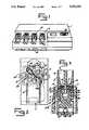
- FIG. 1Perspective view of the analytical work station.
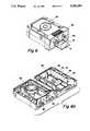
- FIG. 2Top view of filter assembly.
- FIG. 3Cross sectional 3-1 view of FIG. 2.
- FIG. 4Disassembled filter assembly.
- FIG. 4aTop view of the slide.
- FIG. 5Schematic of the vacuum system.
- FIG. 6Top perspective view of the slide reading assembly.
- FIG. 6aInternal perspective view of the slide reading assembly.
- FIG. 7Cross-section of the filter assembly.
- FIG. 7aHoles in inner wall section of housing.
- FIG. 8Schematic diagram of circuit.
- FIG. 9Alternating current response curve.
- FIG. 9aFirst derivative of the curve of FIG. 9.
- FIG. 10Standard curve for DNA determination.
- This inventionencompasses a work station for conducting assays which comprise a filtering assembly, a slide reading assembly, and a slide with a porous filter membrane wherein the slide has a means for aligning the slide within the filter assembly to filter an analyte or analyte complex at a plurality of predetermined locations on the porous filter membrane and also to position the slide in the slide reading assembly so that detection will occur in those same predetermined locations.
- This inventionencompasses an analytical work station which has a filtering assembly, a slide with a porous filter membrane and a slide reading assembly.
- the filtering assemblycomprises a combination of:
- a block with a top and bottom surfacehaving a plurality of channels with inlet ports on the top surface and exit ports on the bottom surface and a first alignment means
- a vacuum platehaving an upper and lower surface wherein the lower surface has a vacuum fitting defining an area on the lower surface, with a plurality of vacuum ports from the upper to lower surface within the area defined by the vacuum fitting, the vacuum plate having a second alignment means;
- a slidedefining an opening which is covered by a porous filter membrane and further having a third alignment means.
- the block and the vacuum platefit together to form a space for removably inserting the slide between the bottom surface of the block and the upper surface of the vacuum plate and the first, second, and third alignment means align the block, vacuum plate, and slide such that the exit ports of the block, porous filter membrane, and vacuum ports are aligned so that when a vacuum is applied through the vacuum fitting, liquids in the block channels separately flow through the exit ports, through the porous filter membrane, and through the vacuum ports so that liquids from one channel do not mix with liquids from other channels on the porous filter membrane.
- the analytes or analyte complexes in the filtered liquidare fixed on the porous filter membrane in a predetermined location so as to substantially concentrate the analyte or complexes of the analyte.
- the slideis a thin flat generally rectangular plastic sheet with a front and rear end.
- the front end of the slidehas a notch as a means for aligning the slide both in a filter assembly and a reading assembly.
- the rear end of the slidehas an area for manually grasping the slide.
- the frontapproximately a third of the slide, defines an opening which is covered with a porous filter membrane.
- a section of the front one third of the slideis narrower than the rear section of the slide.
- the narrower sectionalso serves as a means for aligning the slide in both a filtering assembly and the slide reading assembly.
- the alignment meansprovide for filtration of analyte onto predetermined locations on the porous filter membrane in the filter assembly and for detection of analyte at these same predetermined locations in the slide reading assembly.
- the porous filter membranehas a specific binding substance such as a hapten, for example, biotin so that the porous filter membrane can capture a specifically binding analyte complex at a specific location on the filter membrane.
- a specific binding substancesuch as a hapten, for example, biotin
- biotinfor example, an avidin or streptavidin complex is used in conjunction with a biotin labeled membrane.
- the slide reading assemblyhas a housing with a top, bottom, and inner and outer sidewall sections.
- the inner side wall sectionhas at least one window or a plurality of holes as windows with a photoresponsive electrode mounted above the windows on the inside of the inner wall section so that light from an external source can pass through the holes to the external surface photoresponsive electrode
- the top section of the housinghas an opening for receiving a slide to be analyzed.
- the slidehas a porous filter membrane with analyte or analyte complexes to be determined at predetermined locations on the porous filter.
- the housinghas a means for aligning, the analyte-containing region of the porous filter membrane on the internal surface of the photoresponsive electrode opposite the holes in the housing which allow light to pass to the photoresponsive electrode.
- a resilient plungeris mounted in the outer sidewall section of the housing opposite the photoresponsive electrode.
- the plungerhas a stem and pad which is pivotally mounted on the stem and located within the housing such that when the plunger stem is externally pushed into the housing by a stepping motor the pad compresses the porous membrane against the inner surface of the photoresponsive electrode. This reduces electrolyte volume and improves sensitivity.
- the inner surface of the photoresponsive electrodeis within the liquid chamber and exposed to the liquid.
- the porous filter membraneis aligned above the inner surface of the photoresponsive electrode also in the liquid chamber.
- a light sourcecomprising an array of light emitting diodes (LEDs) for independently irradiating portions of the photoresponsive electrodes with intensity modulated light through the holes in the housing.
- the area of the photoresponsive electrode exposed to intensity modulated lightis opposite the area of the porous filter membrane having filtered analyte or analyte complex.
- the electrical meansincludes a counter electrode or reference electrode and a control electrode, an operational amplifier, and a computer for processing the signal data.
- a reaction between specific binding substancesis conducted in a test tube, for example, the reaction between DNA, enzyme labeled anti-DNA, SS-binding protein bound to a biotin, and avidin or streptavidin.
- This complexis filtered through a biotinylated porous filter membrane such that the (enzyme containing) analyte complex is captured by the porous filter membrane in small spots at a predetermined location on the membrane. The locations of these spots are fixed by the alignment means in the block, slide, and vacuum plate.
- the slideis removed from the filter assembly and placed in the slide reading assembly which contains a substrate to the enzyme in the liquid in the liquid chamber.
- the plungeris pushed in by a stepping motor to press the pad of the plunger against a photoresponsive electrode.
- This decrease in volumeincreases sensitivity by decreasing the amount of pH buffer in the measurement volume.
- the alignment means in the reading assemblyaligns the enzyme-containing spots of the porous filter membrane opposite the holes for light in the housing.
- the reaction of enzyme and enzyme substrateresults in a change in surface potential in the local area of the photoresponsive electrode which is measured by the above electrical means in conjunction with the action of the intensity-modulated light on the photosensitive electrode.
- the filter assemblyprovides for concentrating a complex containing the analyte to be determined in a small area of a porous filter membrane which is predetermined by the aligrunent means. This predetermined location of the spots on the filter membrane can then be aligned with a specific reading location in the slide reading assembly by complimentary alignment means.
- the pad which compresses the porous filter membrane against the photoresponsive electrodeuniformly reduces volume and increases sensitivity. In this way picogram (pg) quantities of analyte such as DNA can readily be determined.
- the filter and slide reading assembliesprovide for filtering and reading of standards, controls and unknowns under similar conditions as well as for the ease of identification of the sample, and for obtaining an analytical result from the same sample.
- FIG. 4ais a top view of the slide.
- the slide 4ais made of a thin plastic sheet and has an opening which is covered with a porous filter membrane 5.
- the notch 3 at the front end of the slide and the angle 25 defined by the narrow and wide portion of the slideserve as means for aligning the slide in the filter assembly and the slide reading assembly. Slits 3a permit the notch to resiliently expand.
- the rear end of the slidehas an area 7 for manually grasping the slide.
- a porous filter membrane suitable for practicing this inventionis described in great detail in Ser. No. 258,894 assigned to the same assignee of this application. Ser. No. 258,894 is incorporated herein by reference.
- the porous filter membraneis capable of filtering from a solution containing a specifically binding complex having an anti-hapten bound to a binding member of the specifically binding complex.
- the material of the porous filter membraneis selected from material to which protein or other macromolecule can be adhered.
- material to which protein or other macromolecule can be adheredA variety of materials may be used. Those skilled in the art will appreciate that porous membranes made of nylon, cellulose acetate, polyolefin, polyacrylamide, nitrocellulose or other porous materials may be employed in the present invention. Other synthetic or naturally occurring materials which will adhere a protein or other macromolecule may also be used. A preferred membrane is made from nitrocellulose. Physical characteristics of the porous filter membrane in the slide are:
- a membrane having 1-10 m mol (per liter of compressed membrane volume) buffering capacityis preferred.
- Haptensare substances which do not elicit antibody formation unless complexed to macromolecules and which may be employed as specific organic materials for which specific binding substances can be provided.
- Antibodies to haptenscan be formed by binding the hapten to a protein so as to elicit an antibody response.
- a specific binding substanceis any substance or group of substances having a specific binding affinity for the hapten to the exclusion of other substances.
- the haptenmust be able to bind to a protein or other macro-molecule directly or through an extended linking group.
- haptenswhich may be used include steroids such as estrone, estradiol, testosterone, pregnanediol and progesterone; vitamins such as B 12 , biotin and folic acid; triiodothyronine, thyroxine, histamine, serotonin, digoxin, prostaglandins, adrenalin, noradrenalin, morphine, vegetable hormones and antibiotics such as penicillin.
- the receptorcan be utilized as the anti-hapten provided the receptor can be isolated in a form specific for the hapten.
- Illustrative haptens which have naturally occurring receptorsinclude thyroxine, many steroids, polypeptides, such as insulin, angiotensin, biotin and many others.
- Receptors for this class of haptensare usually proteins or nucleic acids.
- Extended linking groupsare groups that will bind the hapten to the protein or macro-molecule in such a way that the hapten has better access to the anti-hapten. Where an extended linking group is not needed, a hapten, such as biotin without an extended linking group, is bound to a functional group on a membrane or to a function group on a protein which can be disbursed on the membrane.
- the extended linking group having an hapten bound to one endwill be bound to the protein or macro-molecule with an amide bond; the amine of the amide bond arising from the protein and the carboxyl of the amide bond arising from the carboxy terminus of the extender group.
- Free carboxyl or hydroxyl groups on proteinscan likewise be used.
- the proteins used as carriersinclude, but are not limited to, bovine serum albumin (BSA), bovine gamma globulin, and fibrinogen.
- BSAbovine serum albumin
- a preferred membrane for use with the slidehas 5-20 molecules of biotin bound to bovine serum albumin (BSA)
- BSAis further adhered to the surface of the membrane.
- the preferred linking groupis the following: ##STR1##
- the antibodies employedmay be either polyclonal or monoclonal antibodies and are produced in response to the target antigen of the assay. Methods for the production of antibodies to various biological substances are well known in the art.
- the antigens targeted by the assayinclude, but are not limited to antigens such as IgE, prostatic acid phosphatase, prostate specific antigen, alphafetoprotein, carcinoembryonic antigen, leutenizing hormone, creatine kinase MB, Human Chorionic Gonadotropin (HCG) and other antigens in serum, plasma, urine, or other liquid media.
- antigenssuch as IgE, prostatic acid phosphatase, prostate specific antigen, alphafetoprotein, carcinoembryonic antigen, leutenizing hormone, creatine kinase MB, Human Chorionic Gonadotropin (HCG) and other antigens in serum, plasma, urine, or other liquid media.
- antigenssuch as IgE, prostatic acid phosphatase, prostate specific antigen, alphafetoprotein, carcinoembryonic antigen, leutenizing hormone, creatine kinase MB, Human Chorionic Gonadotropin (HCG
- Polydeoxyribonucleotidescan be determined by reactions with single strand DNA binding protein (SSB) and anti-DNA antibodies.
- SSBsingle strand DNA binding protein
- anti-DNA antibodiesvarious combinations of labeled SSB or anti-DNA and biotinylated SSB or anti-DNA are employed.
- streptavidinis bound to the biotinylated SSB or anti-DNA so that the complex can be bound to the capture membrane having biotin.
- the article in Biochemist, 25:21 (1986)describes the large scale over production of single-strand binding protein (SSB) from E. coli.
- Monoclonal antibodies to DNAhave been used to measure DNA in biological fluids, Journal of Immunolog Methods, 88, (1986) 185-192.
- enzymeswhich may conveniently be employed are, malate dehydrogenase, lipase, delta-5-ketosteroid isomerase, yeast alcohol dehydrogenase, yeast glucose-6-phosphate dehydrogenase, alpha glycerophosphate dehydrogenase, triose phosphate isomerase, horseradish peroxidase, alkaline phosphatase, asparaginase, glucose oxidase, beta-galactosidase, and more preferably, urease. Normally, it is preferred that the enzyme be in a pure form, free of contaminating proteins.
- the preparation of the enzyme-labelled biological substancescan be accomplished in various ways known in the art. Examples of the coupling of biological substances to enzymes are described in, for example, L. A. Steinberger, Immunocytochemistry, Prentice Hall, N.J. (1974).
- the enzyme label on porous filter membraneis made to react with an enzyme substrate and the extent of reaction is measured by the photoresponsive electrodes and methods described in U.S. Pat. Nos. 4,591,550, 4,704,353, and U.S. patent application No. 876,925, filed Jun. 20, 1986 and assigned to the same assignee as this application.
- the slide reading assemblyis an adaption and improvement of these devices to read the predetermined locations on the membrane where the enzyme has been filtered.
- the photoresponsive electrodecan be influenced by a wide variety of redox systems where the redox reaction occurs at the surface of the photoresponsive electrode where the light strikes the surface of the photoresponsive electrode.
- FIG. 1is a perspective view of the analytical work station 1.
- FIG. 2is a top view of a filter assembly which shows a filter block 10, vacuum plate 11 and slide 4
- FIG. 3is a cross-sectional view of 3--3 of FIG. 2.
- the filter block 10has a plurality of channels 12 which narrow from the inlet port 13 to the exit port 14.
- the exit ports 14are centrally located in a smooth surface area 14a at the bottom end of the block.
- the bottom surface of the blockhas a hole 23 as an aligrunent means to align the slide with the vacuum plate 11.
- the blockhas small projections 15 at the lower end of the side walls which are gripped by the clamping mechanism spring clip 17 through opening 16 to fix and release the slide between the filter block 10 and the vacuum plate 11 by turning lever 18 as shown in FIGS. 1 and 3.
- the vacuum plate 11has on its upper surface a plurality of radial cylinders 19 through which pass the vacuum ports 20 as shown in FIG. 3 which is a cross-section of 3--3 of FIG. 2, also see FIG. 4.
- the smooth lower surface of the filter block and the smooth upper surface of the raised cylinders of the vacuum platecompress the membrane 5.
- the spring clips 17follow a cam surface 27a and spread in the upper position allowing an easy removal of the filter assembly from the vacuum. In the lower position the spring clips are closed firmly and without any side forces hold the filter block locked against the vacuum plate. This compression prevents fluid from one filter pathway 21 crossing over to another filter pathway 21a.
- the vacuum platehas a peg 22 which interacts with the hole 23 of the block and the notch 3 of the slide (shown in FIG. 4a) to align the exit ports 14 in the block and the vacuum ports 20 in the vacuum plate. Slits 3a provide for expanding the notch 3 to resiliently clamp the peg 22.
- the vacuum platefurther has a depression 24 which fits the shape of the slide 25 to rigidly fix the slide in place as shown in FIG. 2. Turning 18 in FIGS. 3 and 4 releases the pressure exerted by block 10, and thus permits the slide 4 to be removed from the filtering assembly.
- FIG. 4shows the filter assembly disassembled into its component parts and further illustrates the arrangement of the block 10, manifold bottom 8, slide 4, and vacuum plate 11 as they sit in the vacuum manifold 9. Further illustrated in FIG. 4 are the liquid level sensor 26, manifold insert 27, and check valve 27b which engages vacuum fitting 27c on the vacuum plate 11. FIG. 4 further illustrates how lever 18 interacts with cam 28 and spring block 29 to spring clip 17 which has hole 16 engaged with projection 15 of the filter block 10. Thus turning 18 lowers the block 10 and releases the porous filter membrane 5.
- FIG. 3illustrates the interaction of clamping mechanism 18, 28, 29, 17, 16 and further shows the engagement of spring clip 17 with the manifold insert 27 at point 27a.
- the manifold insert 27engages the vacuum plate 11 at the vacuum fitting 27c.
- the vacuum ports 20lie within the vacuum fitting 27c and the check valve 27b lies within the manifold insert 27. Projections 27d push against the check valve 27b to open the check valve.
- the vacuum systemis schematically illustrated in FIG. 5.
- the vacuum pump 30is controlled by the vacuum pump control 31.
- the vacuum to the vacuum manifold 32is controlled by the vacuum control 33 which operates a proportional valve 34.
- a pressure transducer 35provides for the vacuum sensor output 36.
- the vacuum manifoldserves as an effluent reservoir and as a vacuum reservoir.
- the individual filter assembly receptacle 9 in the manifoldhas a manifold insert with a check valve 27b, which is activated with the insertion of the filter base to start the vacuum flow.
- the liquid level sensor 26determines when the manifold should be emptied of waste fluid.
- the vacuum systemprovides vacuum to pull solutions in the channels of the filter block through the porous filter membrane on the slide by way of the vacuum ports.
- the slide reading assemblyis illustrated in FIGS. 6, 6a, 7 and 7a.
- the housing 40has a slot 41 in the top end 42 for inserting the slide 4.
- the housinghas an area with a plurality of holes 43 or windows in the inner wall section 44 (see FIG. 7a) and a photoresponsive electrode 45 mounted over the holes.
- This photoresponsive electrode 45has a transparent layer of silicon dioxide which defines areas of transparent circular spots 46 which are aligned with the holes 43 in the housing.
- the windows 43 in the housing and transparent circular spots 46permit light to pass from the array of LED's 47 from outside the housing to the surface of the photoresponsive electrode as shown in FIGS. 7 and 7a.
- Within the reading assembly housingis a peg 48 which serves as a means for aligning the slide by engaging the notch 3 (see FIG.
- the housingalso defines a liquid chamber 52 and there is an exit 53 and an entrance port 54 for filling and emptying to liquid chamber 52. The liquid in the liquid chamber is in contact with the photoresponsive electrode and the porous filter membranae.
- the liquidserves as an electrolyte and contains a reagent that reacts with the analyte or analyte complex on the porous filter membrane.
- a reagentthat reacts with the analyte or analyte complex on the porous filter membrane.
- the analyte complexcontains an enzyme
- the liquid in the liquid chamberwill contain an enzyme substrate and this enzyme/enzyme substrate reaction causes a local change in pH on the surface of the photoresponsive electrode.
- the slide reading assemblyhas a plunger 60 resiliently mounted by flexing member 55 in the top of the housing.
- the plunger 60has a stem 61 and a pivotally mounted pad 62.
- the ball and socket mounting 65gives flexibility to the mounted pad 62.
- FIG. 7shows light from LED 47 passing through holes 43 in the inner wall 44 and through the transparent spots 46 on the photoresponsive electrode 45 which are aligned with the predetermined areas 51 in the porous filter membrane 5 where analytes or analyte complexes are located.
- This pivotally mounted pad 62is pushed against the porous filter membrane 5 by a stepping motor 63 which is operatively associated with the stem 61 of the plunger 60.
- This pad 62reduces the volume of liquid above the porous filter membrane and greatly increases the sensitivity of the photoresponsive electrode.
- FIG. 7aillustrates the holes 43 in the inner wall section 44.
- the slideis aligned so that spots on the membrane having analyte or analyte complex are aligned above the irradiated portion of the photoresponsive electrode and the pivotally mounted pad uniformly compresses the areas of the porous filter membrane where the analyte is located to exclude excess volume of buffering electrolyte so as to greatly increase sensitivity of the photoresponsive electrode for measuring potential changes resulting from the reaction of enzyme substrate and enzyme bound to the porous filter membrane due to the presence of analyte or analyte complex.
- the operation of the photoresponsive electrodeincluding the reference electrode, controlling electrode, materials for the electrode, light source, nature of measurable chemical reactions, signal amplification and measurement, types of measurable enzyme and redox reactions and the like are described in great detail in U.S. Pat. Nos. 4,704,353; 4,758,786 and 4,591,550, which are incorporated herein by reference.
- a schematic of an electrical circuit usable in the present inventionis shown in U.S. Pat. No. 4,758,786.
- FIG. 8shows a preferred circuit for use with this invention. Shown in FIG. 8 is a schematic diagram of a computer-controlled electronic circuit which may be used to operate the potentiometric reading device in accordance with the present invention.
- a photoresponsive electrode 45e.g. n-type 10-25 ohm-cm, 100 crystalline silicon
- polished on one sideis covered on the polished side with an insulator 82 which is in contact with an electrolyte 84 enclosed by a chamber wall 86 sealed to the insulator surface by a silicon polymer 88.
- Operational amplifiers 90 and 92together with resistors 94 and 96, reference electrode 98, controlling electrode 100, and digital-to-analog converter (D/A) 118 mounted on master circuit board 102, function to determine the potential of the electrolyte with respect to the bulk of the photoresponsive electrode 45.
- the potential of the photoresponsive electrode 45is held constant at virtual ground by copper lead 106 which is attached to the underside of the photoresponsive electrode 45 through a brass spring and ohmic contact 104.
- Ohmic contact 104is made by evaporation of 99% gold - 1% arsenic onto the non-insulated silicon surface followed by alloying above the gold-silicon eutectic temperature.
- One light-emitting diode (LED) 47 of an array of nine similar LEDsis powered by LED driver 110 so as to irradiate the photoresponsive electrode at the desired X-Y-coordinate with light of 50% duty cycle, on/off-modulated intensity. Any one of the nine similar LEDs may be selected for light intensity modulation by computer 112 which acts on a switching circuit in LED driver 110.
- the frequency of intensity-modulationis determined by LED driver 110 to be about 10 KHz.
- Current-to voltage converter 107measures the alternating photocurrent generated in photoresponsive electrode 45.
- the voltage output of current-to-voltage converter 107is filtered by bandpass filter 109 and rectified by rectifier 111 to give a dc voltage output that is proportional to the alternating current amplitude.
- This analog dc voltage outputis converted into digital form by analog-to digital converter (A/D) 116 and stored as data in the memory of computer 112.
- A/Danalog-to digital converter
- Experimentally-acquired datamay be viewed on CRT display 120 and permanently displayed by printer 122.
- modulated currentis applied from LED driver 110 to cause LED 47 to be modulated in intensity.
- the output of D/A 118is ramped by a program in computer 112 so as to ramp the potential of electrolyte 84.
- the electrolyte potentialaffects the electrical field within the photoresponsive electrode which, in turn, affects the alternating current generated in the illuminated portion of photoresponsive electrode 45, flowing through lead 106, and measured by current-to voltage converter 107.
- FIG. 9shows a typical alternating current response to changes in the electrolyte potential is determined.
- the values of current vs. electrolyte potentialare stored for subsequent analysis of the rate of change in this relationship.
- FIG. 9is determined, i.e. that point at which the resulting alternating photocurrent finds its maximum change for a given change in electrolyte potential.
- a convenient way of determining this point of maximum slope of the photocurrent of FIG. 9is to take the second derivative and determine where the second derivative is equal to zero. This is depicted in the graph of FIG. 9a.
- the data near the maximise or minimxm alternating photocurrentsare not used in the analysis. For example, the data points associated with photocurrent less than 10% and more than 90% of the maximum alternating photocurrent are neglected.
- the measured rate of change in the relationship between the alternating photocurrent amplitude and the electrolyte potentialis determined by the rate of change of the electrostatic surface potential present at the electrolyte-exposed surface of the photoresponsive electrode at the X-Y coordinate of irradiation with intensity-modulated light (Science 240, 1182-1185, May 27, 1988).
- This surface potentialis determined by the pH of the electrolyte exposed to the surface when a pH sensitive surface, e.g. silicon nitride is employed and is redox potential sensitive when the surface is a noble metal, e.g. platinum or gold (see U.S. Ser. No. 231,981, 072,168, and 065,418).
- a photoresponsive electrodecan be influenced by the redox potential of the medium adjacent the electrode surface.
- Various redox systemscan be employed, enzyme reactions, particularly oxidoreductases, e.g., glucose oxidase, peroxidase, uricase, AND or NADP dependent dehydrogenases, naturally occurring electron transfer agents, e.g. , ferridoxin, ferritin, cytochrome C, and cytochrome b 2 , organic electron donors and acceptor agents, e.g.
- metallocenese.g., ferrocenium, naphthoquinone, N,N'-dimethyl 4,4'-dipyridyl, etc.
- inorganic redox agentse.g., ferri- and ferrocyanide, chloronium ion, cuprous and cupric ammonium halide, etc.
- the slide reading assemblyhas a photoresponsive electrode with a multiplicity of measurement sites, and includes both a reference and a controlling electrode, as shown in FIG. 8.
- the reference electrodemay be made optional by shorting the output of operational amplifier 90 and the input of operational amplifier 92, shown in FIG. 8, and making a common connection to a single counter electrode placed in the electrolyte 84.
- the counter electrodemay be extremely simply, namely a foil or wire of a metal such as platinum, gold, irridium, titatium, etc. which is inert to the electrolyte.
- the photoresponsive electrodehas a multiplicity of measurement sites that includes at least one control site where no analyte is present and is thereby able to, by difference, measure the rate of potential change generated by the chemical reaction due to presence of the analyte at other sites at the surface of the photoresponsive electrode.
- the stepper motor 63 in FIG. 7is engaged with the plunger stem 61 to push the pad 62 of the plunger against the porous filter membrane.
- a chemical reactionoccurs at the surface of the photoresponsive electrode between reagent in the liquid such as an enzyme substrate with an enzyme which is part of an analyte complex.
- Light from an LED 47goes through the holes 43 in the housing and is absorbed within the photoresponsive electrode 45.
- the chemical reactionsuch as the reaction of urease with urea to release ammonia and carbon dioxide causes a change in pH or redox potential of the electrolyte. This in turn affects the surface potential of the photoresponsive electrode, which in turn alters the effect of light on the photoresponsive electrode.
- the analytical work stationpermits the determination of the picogram (pg) qualities of DNA at quantities as slow as 2 pg over a dynamic range of 2-200 pg.
Landscapes
- Health & Medical Sciences (AREA)
- Immunology (AREA)
- Life Sciences & Earth Sciences (AREA)
- Chemical & Material Sciences (AREA)
- Engineering & Computer Science (AREA)
- Analytical Chemistry (AREA)
- Physics & Mathematics (AREA)
- Hematology (AREA)
- Pathology (AREA)
- Molecular Biology (AREA)
- Urology & Nephrology (AREA)
- General Physics & Mathematics (AREA)
- General Health & Medical Sciences (AREA)
- Biochemistry (AREA)
- Biomedical Technology (AREA)
- Cell Biology (AREA)
- Medicinal Chemistry (AREA)
- Food Science & Technology (AREA)
- Biotechnology (AREA)
- Microbiology (AREA)
- Investigating Or Analysing Materials By The Use Of Chemical Reactions (AREA)
- Investigating Or Analysing Biological Materials (AREA)
- Apparatus Associated With Microorganisms And Enzymes (AREA)
Abstract
Description
______________________________________ (a) pore size: 0.25 to 12.0 μm (b) thickness: 50 to 180 μm (c) bubble point: 75 to 6 psi ______________________________________
______________________________________ Porous Filter Membrane Complex ______________________________________ membrane - hapten anti hapten-Ab Ag-Ab (enzyme) membrane - (biotin) (streptavidin)-Ab' Ag' Ab (enzyme) ______________________________________
______________________________________ Porous Filter Membrane Complex ______________________________________ membrane-biotin streptavidin-biotin-anti-DNA/ DNA-SSB-enzyme ______________________________________
______________________________________ DNA Assay Standard Curve ______________________________________ Membrane: biotin-BSA coated nitrocellulose membrane (0.8μ pore side). DNA sample: 0, 5, 10, 25, 50, 100, 150, 200 pg of single- stranded Calf thymus DNA in 0.5 ml of phosphate bufferedsaline buffer 50 mm NaPO.sub.4, 150 mm NaCl, 1 mm EDTA; 0.05% sodium azide pH 7.0. Reagent: 0.5 μg/ml Streptavidin, 1 ng/ml SSB-biotin, 250 ng/ml anti-DNA-urease, 0.1% BSA in 10 mM tris.HCl buffer, 1 mM EDTA (pH 7.4) plus 0.25% triton X-100, 0.05% sodium azide. Assay Protocol: 500 μl of DNA sample was incubated with 1000 μl of reagent at 37° for 60 minutes. The mixture was filtered through the biotin-BSA coated membrane at a flow rate of about 100 μl/min. The membrane was then washed with 1 cc of wash buffer (10 mm NaPO.sub.4, 100 mm NaCl, 0.05% Tween 20, 0.05% sodium azide, pH 6.5) at a maximum flow rate of about 6 ml/min). After washing, the slide was transferred to the slide reading assembly where the liquid contains as 100 mM urea in the wash as substrate. ______________________________________
______________________________________ Results Rate of Signal DNA (Pg/sample) (μV/Sec) ______________________________________ 0 42.0 5 75.5 10 91.0 25 177.5 50 331 100 656 150 938 200 1353 ______________________________________
Claims (1)
Priority Applications (4)
| Application Number | Priority Date | Filing Date | Title |
|---|---|---|---|
| US07/297,767US5252293A (en) | 1989-01-17 | 1989-01-17 | Analytical slide with porous filter membrane |
| CA002007923ACA2007923A1 (en) | 1989-01-17 | 1990-01-17 | Analytical work station |
| PCT/US1990/000168WO1990008313A1 (en) | 1989-01-17 | 1990-01-17 | Analytical work station |
| US08/361,980US5529752A (en) | 1989-01-17 | 1994-12-22 | Analytical work station |
Applications Claiming Priority (1)
| Application Number | Priority Date | Filing Date | Title |
|---|---|---|---|
| US07/297,767US5252293A (en) | 1989-01-17 | 1989-01-17 | Analytical slide with porous filter membrane |
Related Child Applications (1)
| Application Number | Title | Priority Date | Filing Date |
|---|---|---|---|
| US3316993ADivision | 1989-01-17 | 1993-03-16 |
Publications (1)
| Publication Number | Publication Date |
|---|---|
| US5252293Atrue US5252293A (en) | 1993-10-12 |
Family
ID=23147661
Family Applications (2)
| Application Number | Title | Priority Date | Filing Date |
|---|---|---|---|
| US07/297,767Expired - LifetimeUS5252293A (en) | 1989-01-17 | 1989-01-17 | Analytical slide with porous filter membrane |
| US08/361,980Expired - Fee RelatedUS5529752A (en) | 1989-01-17 | 1994-12-22 | Analytical work station |
Family Applications After (1)
| Application Number | Title | Priority Date | Filing Date |
|---|---|---|---|
| US08/361,980Expired - Fee RelatedUS5529752A (en) | 1989-01-17 | 1994-12-22 | Analytical work station |
Country Status (3)
| Country | Link |
|---|---|
| US (2) | US5252293A (en) |
| CA (1) | CA2007923A1 (en) |
| WO (1) | WO1990008313A1 (en) |
Cited By (41)
| Publication number | Priority date | Publication date | Assignee | Title |
|---|---|---|---|---|
| WO1994016329A1 (en)* | 1993-01-13 | 1994-07-21 | Abbott Laboratories | Methods for solid phase capture in immunoassays |
| US5484572A (en)* | 1993-10-01 | 1996-01-16 | Taiho Industries Co., Ltd. | Apparatus for collecting medical test specimens |
| US5515170A (en)* | 1994-09-08 | 1996-05-07 | Lifescan, Inc. | Analyte detection device having a serpentine passageway for indicator strips |
| US5526120A (en)* | 1994-09-08 | 1996-06-11 | Lifescan, Inc. | Test strip with an asymmetrical end insuring correct insertion for measuring |
| USD373829S (en) | 1994-11-04 | 1996-09-17 | Applied Research Systems Ars Holding N.V | Holder for an assay device |
| US5563031A (en)* | 1994-09-08 | 1996-10-08 | Lifescan, Inc. | Highly stable oxidative coupling dye for spectrophotometric determination of analytes |
| US5563042A (en) | 1986-08-13 | 1996-10-08 | Lifescan, Inc. | Whole blood glucose test strip |
| US5780304A (en)* | 1994-09-08 | 1998-07-14 | Lifescan, Inc. | Method and apparatus for analyte detection having on-strip standard |
| US5879951A (en) | 1997-01-29 | 1999-03-09 | Smithkline Diagnostics, Inc. | Opposable-element assay device employing unidirectional flow |
| US5939252A (en) | 1997-05-09 | 1999-08-17 | Lennon; Donald J. | Detachable-element assay device |
| US6297018B1 (en) | 1998-04-17 | 2001-10-02 | Ljl Biosystems, Inc. | Methods and apparatus for detecting nucleic acid polymorphisms |
| US6335203B1 (en) | 1994-09-08 | 2002-01-01 | Lifescan, Inc. | Optically readable strip for analyte detection having on-strip orientation index |
| US6398956B1 (en) | 1999-05-28 | 2002-06-04 | Bio/Data Corporation | Method and apparatus for directly sampling a fluid for microfiltration |
| US6458326B1 (en) | 1999-11-24 | 2002-10-01 | Home Diagnostics, Inc. | Protective test strip platform |
| US6511814B1 (en) | 1999-03-26 | 2003-01-28 | Idexx Laboratories, Inc. | Method and device for detecting analytes in fluids |
| US20030021725A1 (en)* | 1999-08-19 | 2003-01-30 | Caliper Technologies Corp. | Indicator components for microfluidic systems |
| US6525330B2 (en) | 2001-02-28 | 2003-02-25 | Home Diagnostics, Inc. | Method of strip insertion detection |
| US6541266B2 (en) | 2001-02-28 | 2003-04-01 | Home Diagnostics, Inc. | Method for determining concentration of an analyte in a test strip |
| US6551842B1 (en) | 1999-03-26 | 2003-04-22 | Idexx Laboratories, Inc. | Method and device for detecting analytes in fluids |
| US6602719B1 (en) | 1999-03-26 | 2003-08-05 | Idexx Laboratories, Inc. | Method and device for detecting analytes in fluids |
| US20030228705A1 (en)* | 2002-06-06 | 2003-12-11 | Anthony Chan | Apparatus and method for the measurement of cells in biological samples |
| US20030232321A1 (en)* | 2002-06-15 | 2003-12-18 | Lin Jinn-Nan | Test strip for detection of analyte and methods of use |
| US6750039B1 (en) | 2001-03-21 | 2004-06-15 | Boston Probes, Inc. | Filtration apparatus and method for the separation of microscopic entities from a fluid |
| US6982431B2 (en) | 1998-08-31 | 2006-01-03 | Molecular Devices Corporation | Sample analysis systems |
| US20060060531A1 (en)* | 1999-05-28 | 2006-03-23 | Bio/Data Corporation | Method and apparatus for directly sampling a fluid for microfiltration |
| US7070921B2 (en) | 2000-04-28 | 2006-07-04 | Molecular Devices Corporation | Molecular modification assays |
| US20070105145A1 (en)* | 2001-03-09 | 2007-05-10 | Applera Corporation | Methods, Kits and Compositions Pertaining to Combination Oligomers and Libraries for Their Preparation |
| US20070160998A1 (en)* | 2004-02-11 | 2007-07-12 | Van Beuningen Marinus G J | Device for analyzing an interaction between target and probe molecules |
| US7390665B2 (en) | 2001-02-28 | 2008-06-24 | Gilmour Steven B | Distinguishing test types through spectral analysis |
| US7632651B2 (en) | 1997-09-15 | 2009-12-15 | Mds Analytical Technologies (Us) Inc. | Molecular modification assays |
| USRE41309E1 (en) | 1997-12-05 | 2010-05-04 | Roche Diagnostics Operations, Inc. | Electrochemical biosensor test strip |
| US7744817B2 (en)* | 2003-08-11 | 2010-06-29 | Sakura Finetek U.S.A., Inc. | Manifold assembly |
| US7745142B2 (en) | 1997-09-15 | 2010-06-29 | Molecular Devices Corporation | Molecular modification assays |
| US7767152B2 (en) | 2003-08-11 | 2010-08-03 | Sakura Finetek U.S.A., Inc. | Reagent container and slide reaction retaining tray, and method of operation |
| WO2011056598A3 (en)* | 2009-10-26 | 2011-10-06 | Ikonisys, Inc. | Membrane filter system and apparatus |
| US20120258519A1 (en)* | 2011-04-10 | 2012-10-11 | Therapeutic Proteins Inc. | Protein Harvesting |
| US8459509B2 (en) | 2006-05-25 | 2013-06-11 | Sakura Finetek U.S.A., Inc. | Fluid dispensing apparatus |
| US8580568B2 (en) | 2011-09-21 | 2013-11-12 | Sakura Finetek U.S.A., Inc. | Traceability for automated staining system |
| US8752732B2 (en) | 2011-02-01 | 2014-06-17 | Sakura Finetek U.S.A., Inc. | Fluid dispensing system |
| US8932543B2 (en) | 2011-09-21 | 2015-01-13 | Sakura Finetek U.S.A., Inc. | Automated staining system and reaction chamber |
| US9518899B2 (en) | 2003-08-11 | 2016-12-13 | Sakura Finetek U.S.A., Inc. | Automated reagent dispensing system and method of operation |
Families Citing this family (28)
| Publication number | Priority date | Publication date | Assignee | Title |
|---|---|---|---|---|
| JPH06504851A (en)* | 1991-11-27 | 1994-06-02 | ジーイーシー − マーコニ リミテッド | Analyte immunological detection device |
| US6318902B1 (en)* | 1996-03-12 | 2001-11-20 | 3M Innovative Properties Company | Optical connector assembly using partial large diameter alignment features |
| US5958714A (en)* | 1996-10-02 | 1999-09-28 | Safety Associates, Inc. | Test kits for determining at least two specific analytes in foods and other complex matrices |
| US6815174B1 (en)* | 1996-11-28 | 2004-11-09 | Edgardo Poskus | Thioredoxin-glutamate decarboxylase 65 fusion protein |
| US6071748A (en) | 1997-07-16 | 2000-06-06 | Ljl Biosystems, Inc. | Light detection device |
| US5965410A (en)* | 1997-09-02 | 1999-10-12 | Caliper Technologies Corp. | Electrical current for controlling fluid parameters in microchannels |
| AU746098B2 (en)* | 1997-09-02 | 2002-04-18 | Caliper Life Sciences, Inc. | Microfluidic system with electrofluidic and electrothermal controls |
| US6576476B1 (en) | 1998-09-02 | 2003-06-10 | Ljl Biosystems, Inc. | Chemiluminescence detection method and device |
| US6825921B1 (en) | 1999-11-10 | 2004-11-30 | Molecular Devices Corporation | Multi-mode light detection system |
| DE19746874A1 (en)* | 1997-10-23 | 1999-04-29 | Qiagen Gmbh | Isolation of nucleic acids |
| US6174675B1 (en) | 1997-11-25 | 2001-01-16 | Caliper Technologies Corp. | Electrical current for controlling fluid parameters in microchannels |
| WO2001031333A1 (en)* | 1999-10-26 | 2001-05-03 | Genometrix Genomics Incorporated | Process for requesting biological experiments and for the delivery of experimental information |
| US8111401B2 (en) | 1999-11-05 | 2012-02-07 | Robert Magnusson | Guided-mode resonance sensors employing angular, spectral, modal, and polarization diversity for high-precision sensing in compact formats |
| US7217574B2 (en) | 2000-10-30 | 2007-05-15 | Sru Biosystems, Inc. | Method and apparatus for biosensor spectral shift detection |
| US7023544B2 (en) | 2000-10-30 | 2006-04-04 | Sru Biosystems, Inc. | Method and instrument for detecting biomolecular interactions |
| US7371562B2 (en) | 2000-10-30 | 2008-05-13 | Sru Biosystems, Inc. | Guided mode resonant filter biosensor using a linear grating surface structure |
| US7094595B2 (en) | 2000-10-30 | 2006-08-22 | Sru Biosystems, Inc. | Label-free high-throughput optical technique for detecting biomolecular interactions |
| US7142296B2 (en) | 2000-10-30 | 2006-11-28 | Sru Biosystems, Inc. | Method and apparatus for detecting biomolecular interactions |
| US7300803B2 (en) | 2000-10-30 | 2007-11-27 | Sru Biosystems, Inc. | Label-free methods for performing assays using a colorimetric resonant reflectance optical biosensor |
| US7153702B2 (en) | 2000-10-30 | 2006-12-26 | Sru Biosystems, Inc. | Label-free methods for performing assays using a colorimetric resonant reflectance optical biosensor |
| US7175980B2 (en) | 2000-10-30 | 2007-02-13 | Sru Biosystems, Inc. | Method of making a plastic colorimetric resonant biosensor device with liquid handling capabilities |
| US7575939B2 (en) | 2000-10-30 | 2009-08-18 | Sru Biosystems, Inc. | Optical detection of label-free biomolecular interactions using microreplicated plastic sensor elements |
| US7615339B2 (en) | 2000-10-30 | 2009-11-10 | Sru Biosystems, Inc. | Method for producing a colorimetric resonant reflection biosensor on rigid surfaces |
| US6837988B2 (en) | 2001-06-12 | 2005-01-04 | Lifescan, Inc. | Biological fluid sampling and analyte measurement devices and methods |
| US6576416B2 (en)* | 2001-06-19 | 2003-06-10 | Lifescan, Inc. | Analyte measurement device and method of use |
| US7429492B2 (en) | 2002-09-09 | 2008-09-30 | Sru Biosystems, Inc. | Multiwell plates with integrated biosensors and membranes |
| NZ582473A (en) | 2007-07-11 | 2011-12-22 | Sru Biosystems Inc | Methods of identifying modulators of ion channels using a colorimetric resonant reflectance optical biosensor |
| US9134307B2 (en) | 2007-07-11 | 2015-09-15 | X-Body, Inc. | Method for determining ion channel modulating properties of a test reagent |
Citations (10)
| Publication number | Priority date | Publication date | Assignee | Title |
|---|---|---|---|---|
| US3146163A (en)* | 1962-01-23 | 1964-08-25 | John H Brewer | Apparatus for separating certain components from blood |
| US4299916A (en)* | 1979-12-26 | 1981-11-10 | Syva Company | Preferential signal production on a surface in immunoassays |
| US4366241A (en)* | 1980-08-07 | 1982-12-28 | Syva Company | Concentrating zone method in heterogeneous immunoassays |
| EP0191640A2 (en)* | 1985-02-14 | 1986-08-20 | Abbott Laboratories | Concentrating immunochemical test strip |
| WO1988004428A1 (en)* | 1986-12-12 | 1988-06-16 | Iq (Bio) Limited | Device and method for biochemical assay |
| US4849330A (en)* | 1984-04-27 | 1989-07-18 | Molecular Devices Corporation | Photoresponsive redox detection and discrimination |
| US4934817A (en)* | 1987-12-09 | 1990-06-19 | Lre Relais+Elektronik Gmbh | Device with detachable test strip holder for optically evaluating a test strip |
| US4948737A (en)* | 1989-01-05 | 1990-08-14 | Eastman Kodak Company | Cartridge for properly receiving test elements |
| US4960692A (en)* | 1986-03-18 | 1990-10-02 | Fisher Scientific Company | Assay employing binding pair members on particles and on a filter or membrane |
| US4960691A (en)* | 1986-09-29 | 1990-10-02 | Abbott Laboratories | Chromatographic test strip for determining ligands or receptors |
Family Cites Families (24)
| Publication number | Priority date | Publication date | Assignee | Title |
|---|---|---|---|---|
| FR2353856A1 (en)* | 1976-06-02 | 1977-12-30 | Chateau Guy | TAPE INTENDED TO BE USED AS A SUPPORT FOR A REACTION FOR EXAMPLE CHEMICAL OR BIOCHEMICAL, AND ANALYSIS PROCESS IMPLEMENTING IT |
| US4159875A (en)* | 1976-10-21 | 1979-07-03 | Abbott Laboratories | Specimen holder |
| US4317726A (en)* | 1981-02-12 | 1982-03-02 | The United States Of America As Represented By The Secretary Of The Army | Microbial filter assembly |
| US4497259A (en)* | 1983-01-07 | 1985-02-05 | Titterton John D | Convertible freight car |
| US4704255A (en)* | 1983-07-15 | 1987-11-03 | Pandex Laboratories, Inc. | Assay cartridge |
| US4493815A (en)* | 1983-07-28 | 1985-01-15 | Bio-Rad Laboratories, Inc. | Supporting and filtering biochemical test plate assembly |
| EP0154147B1 (en)* | 1984-01-25 | 1989-04-05 | Fuji Photo Film Co., Ltd. | Apparatus for measuring ionic activity |
| US4704353A (en)* | 1984-04-27 | 1987-11-03 | Molecular Devices Corporation | Photoresponsive redox detection and discrimination |
| DE3585780D1 (en)* | 1984-12-24 | 1992-05-07 | Abbott Lab | ANALYTICAL DEVICE AND METHOD FOR USE THEREOF. |
| JPS61198041A (en)* | 1985-02-28 | 1986-09-02 | Konishiroku Photo Ind Co Ltd | Biochemical-analyzing instrument |
| JPH076992B2 (en)* | 1985-06-21 | 1995-01-30 | 富士写真フイルム株式会社 | Chemical analyzer |
| DE3786087T2 (en)* | 1986-02-07 | 1993-09-16 | Fuji Photo Film Co Ltd | DEVICE FOR CHEMICAL ANALYSIS. |
| US4777021A (en)* | 1986-04-25 | 1988-10-11 | Richard K. Wertz | Manifold vacuum device for biochemical and immunological uses |
| US4915812A (en)* | 1986-06-20 | 1990-04-10 | Molecular Devices Corporation | Zero volume cell |
| US4911794A (en)* | 1986-06-20 | 1990-03-27 | Molecular Devices Corporation | Measuring with zero volume cell |
| US4758786A (en)* | 1986-08-06 | 1988-07-19 | Molecular Devices Corporation | Method of analyzing semiconductor systems |
| US4834946A (en)* | 1987-02-05 | 1989-05-30 | Levin Andrew E | Apparatus for blot screening numerous, small volume, antibody solutions |
| US4787988A (en)* | 1987-02-20 | 1988-11-29 | Biomedical Research And Development Laboratories, Inc. | Cell harvester |
| US4963815A (en)* | 1987-07-10 | 1990-10-16 | Molecular Devices Corporation | Photoresponsive electrode for determination of redox potential |
| GB8720253D0 (en)* | 1987-08-27 | 1987-10-07 | Cogent Ltd | Assay systems |
| US5037613A (en)* | 1989-03-16 | 1991-08-06 | Eastman Kodak Company | Incubator |
| US5039493A (en)* | 1990-05-04 | 1991-08-13 | The United States Of America As Represented By The Secretary Of The Navy | Positive pressure blotting apparatus with hydropholic filter means |
| US5075079A (en)* | 1990-05-21 | 1991-12-24 | Technicon Instruments Corporation | Slide analysis system |
| DE4041905A1 (en)* | 1990-12-27 | 1992-07-02 | Boehringer Mannheim Gmbh | TEST CARRIER ANALYSIS SYSTEM |
- 1989
- 1989-01-17USUS07/297,767patent/US5252293A/ennot_activeExpired - Lifetime
- 1990
- 1990-01-17WOPCT/US1990/000168patent/WO1990008313A1/enunknown
- 1990-01-17CACA002007923Apatent/CA2007923A1/ennot_activeAbandoned
- 1994
- 1994-12-22USUS08/361,980patent/US5529752A/ennot_activeExpired - Fee Related
Patent Citations (11)
| Publication number | Priority date | Publication date | Assignee | Title |
|---|---|---|---|---|
| US3146163A (en)* | 1962-01-23 | 1964-08-25 | John H Brewer | Apparatus for separating certain components from blood |
| US4299916A (en)* | 1979-12-26 | 1981-11-10 | Syva Company | Preferential signal production on a surface in immunoassays |
| US4366241A (en)* | 1980-08-07 | 1982-12-28 | Syva Company | Concentrating zone method in heterogeneous immunoassays |
| US4366241B1 (en)* | 1980-08-07 | 1988-10-18 | ||
| US4849330A (en)* | 1984-04-27 | 1989-07-18 | Molecular Devices Corporation | Photoresponsive redox detection and discrimination |
| EP0191640A2 (en)* | 1985-02-14 | 1986-08-20 | Abbott Laboratories | Concentrating immunochemical test strip |
| US4960692A (en)* | 1986-03-18 | 1990-10-02 | Fisher Scientific Company | Assay employing binding pair members on particles and on a filter or membrane |
| US4960691A (en)* | 1986-09-29 | 1990-10-02 | Abbott Laboratories | Chromatographic test strip for determining ligands or receptors |
| WO1988004428A1 (en)* | 1986-12-12 | 1988-06-16 | Iq (Bio) Limited | Device and method for biochemical assay |
| US4934817A (en)* | 1987-12-09 | 1990-06-19 | Lre Relais+Elektronik Gmbh | Device with detachable test strip holder for optically evaluating a test strip |
| US4948737A (en)* | 1989-01-05 | 1990-08-14 | Eastman Kodak Company | Cartridge for properly receiving test elements |
Cited By (81)
| Publication number | Priority date | Publication date | Assignee | Title |
|---|---|---|---|---|
| US6268162B1 (en) | 1986-08-13 | 2001-07-31 | Lifescan, Inc. | Reflectance measurement of analyte concentration with automatic initiation of timing |
| US6821483B2 (en) | 1986-08-13 | 2004-11-23 | Lifescan, Inc. | Reagents test strip with alignment notch |
| US6858401B2 (en) | 1986-08-13 | 2005-02-22 | Lifescan, Inc. | Minimum procedure system for the determination of analytes |
| US6881550B2 (en) | 1986-08-13 | 2005-04-19 | Roger Phillips | Method for the determination of glucose employing an apparatus emplaced matrix |
| US6887426B2 (en) | 1986-08-13 | 2005-05-03 | Roger Phillips | Reagents test strip adapted for receiving an unmeasured sample while in use in an apparatus |
| US5563042A (en) | 1986-08-13 | 1996-10-08 | Lifescan, Inc. | Whole blood glucose test strip |
| US5843692A (en) | 1986-08-13 | 1998-12-01 | Lifescan, Inc. | Automatic initiation of a time interval for measuring glucose concentration in a sample of whole blood |
| WO1994016329A1 (en)* | 1993-01-13 | 1994-07-21 | Abbott Laboratories | Methods for solid phase capture in immunoassays |
| US5484572A (en)* | 1993-10-01 | 1996-01-16 | Taiho Industries Co., Ltd. | Apparatus for collecting medical test specimens |
| US5563031A (en)* | 1994-09-08 | 1996-10-08 | Lifescan, Inc. | Highly stable oxidative coupling dye for spectrophotometric determination of analytes |
| US5780304A (en)* | 1994-09-08 | 1998-07-14 | Lifescan, Inc. | Method and apparatus for analyte detection having on-strip standard |
| US6335203B1 (en) | 1994-09-08 | 2002-01-01 | Lifescan, Inc. | Optically readable strip for analyte detection having on-strip orientation index |
| US20030049168A1 (en)* | 1994-09-08 | 2003-03-13 | Patel Harshad Ishwarbhai | Optically readable strip for analyte detection having on-strip orientation index |
| US5526120A (en)* | 1994-09-08 | 1996-06-11 | Lifescan, Inc. | Test strip with an asymmetrical end insuring correct insertion for measuring |
| US6491870B2 (en) | 1994-09-08 | 2002-12-10 | Lifescan, Inc. | Optically readable strip for analyte detection having on-strip orientation index |
| US5515170A (en)* | 1994-09-08 | 1996-05-07 | Lifescan, Inc. | Analyte detection device having a serpentine passageway for indicator strips |
| USD373829S (en) | 1994-11-04 | 1996-09-17 | Applied Research Systems Ars Holding N.V | Holder for an assay device |
| US5879951A (en) | 1997-01-29 | 1999-03-09 | Smithkline Diagnostics, Inc. | Opposable-element assay device employing unidirectional flow |
| US5939252A (en) | 1997-05-09 | 1999-08-17 | Lennon; Donald J. | Detachable-element assay device |
| US7632651B2 (en) | 1997-09-15 | 2009-12-15 | Mds Analytical Technologies (Us) Inc. | Molecular modification assays |
| US7745142B2 (en) | 1997-09-15 | 2010-06-29 | Molecular Devices Corporation | Molecular modification assays |
| USRE43815E1 (en) | 1997-12-05 | 2012-11-20 | Roche Diagnostics Operations, Inc. | Electrochemical biosensor test strip |
| USRE42924E1 (en) | 1997-12-05 | 2011-11-15 | Roche Diagnostics Operations, Inc. | Electrochemical biosensor test strip |
| USRE42560E1 (en) | 1997-12-05 | 2011-07-19 | Roche Diagnostics Operations, Inc. | Electrochemical biosensor test strip |
| USRE41309E1 (en) | 1997-12-05 | 2010-05-04 | Roche Diagnostics Operations, Inc. | Electrochemical biosensor test strip |
| USRE42953E1 (en) | 1997-12-05 | 2011-11-22 | Roche Diagnostics Operations, Inc. | Electrochemical biosensor test strip |
| US6297018B1 (en) | 1998-04-17 | 2001-10-02 | Ljl Biosystems, Inc. | Methods and apparatus for detecting nucleic acid polymorphisms |
| US6982431B2 (en) | 1998-08-31 | 2006-01-03 | Molecular Devices Corporation | Sample analysis systems |
| US6511814B1 (en) | 1999-03-26 | 2003-01-28 | Idexx Laboratories, Inc. | Method and device for detecting analytes in fluids |
| US6551842B1 (en) | 1999-03-26 | 2003-04-22 | Idexx Laboratories, Inc. | Method and device for detecting analytes in fluids |
| US6602719B1 (en) | 1999-03-26 | 2003-08-05 | Idexx Laboratories, Inc. | Method and device for detecting analytes in fluids |
| US20040217059A1 (en)* | 1999-05-28 | 2004-11-04 | Bio/Data Corporation | Method and apparatus for directly sampling a fluid for microfiltration |
| US20020084215A1 (en)* | 1999-05-28 | 2002-07-04 | Bio/Data Corporation | Method and apparatus for directly sampling a fluid for microfiltration |
| US6398956B1 (en) | 1999-05-28 | 2002-06-04 | Bio/Data Corporation | Method and apparatus for directly sampling a fluid for microfiltration |
| US6926834B2 (en) | 1999-05-28 | 2005-08-09 | Bio/Data Corporation | Method and apparatus for directly sampling a fluid for microfiltration |
| US7288195B2 (en) | 1999-05-28 | 2007-10-30 | Bio/Data Corporation | Method and apparatus for directly sampling a fluid for microfiltration |
| US20060060531A1 (en)* | 1999-05-28 | 2006-03-23 | Bio/Data Corporation | Method and apparatus for directly sampling a fluid for microfiltration |
| US6740240B2 (en) | 1999-05-28 | 2004-05-25 | Bio/Data Corporation | Method and apparatus for directly sampling a fluid for microfiltration |
| US20030021725A1 (en)* | 1999-08-19 | 2003-01-30 | Caliper Technologies Corp. | Indicator components for microfluidic systems |
| US6458326B1 (en) | 1999-11-24 | 2002-10-01 | Home Diagnostics, Inc. | Protective test strip platform |
| US6979571B2 (en) | 1999-11-24 | 2005-12-27 | Home Diagnostics, Inc. | Method of using a protective test strip platform for optical meter apparatus |
| US7070921B2 (en) | 2000-04-28 | 2006-07-04 | Molecular Devices Corporation | Molecular modification assays |
| US7390665B2 (en) | 2001-02-28 | 2008-06-24 | Gilmour Steven B | Distinguishing test types through spectral analysis |
| US6541266B2 (en) | 2001-02-28 | 2003-04-01 | Home Diagnostics, Inc. | Method for determining concentration of an analyte in a test strip |
| US6525330B2 (en) | 2001-02-28 | 2003-02-25 | Home Diagnostics, Inc. | Method of strip insertion detection |
| US20080125332A1 (en)* | 2001-03-09 | 2008-05-29 | Applera Corporation. | Methods, Kits and Compositions Pertaining to Combination Oligomers and Libraries for Their Preparation |
| US7566420B1 (en) | 2001-03-09 | 2009-07-28 | Boston Probes, Inc. | Methods, kits and compositions pertaining to combination oligomers and libraries for their preparation |
| US20080085837A1 (en)* | 2001-03-09 | 2008-04-10 | Applera Corporation | Methods, Kits and Compositions Pertaining to Combination Oligomers and Libraries for Their Preparation |
| US20080206747A1 (en)* | 2001-03-09 | 2008-08-28 | Applera Coporation | Methods, Kits and Compositions Pertaining to Combination Oligomers and Libraries for Their Preparation |
| US20080220987A1 (en)* | 2001-03-09 | 2008-09-11 | Applera Corporation. | Methods, Kits and Compositions Pertaining to Combination Oligomers and Libraries for Their Preparation |
| US20080269074A1 (en)* | 2001-03-09 | 2008-10-30 | Applera Corporation | Methods, Kits and Compositions Pertaining to Combination Oligomers and Libraries for Their Preparation |
| US20090163381A1 (en)* | 2001-03-09 | 2009-06-25 | Applera Corporation. | Methods, Kits and Compositions Pertaining to Combination Oligomers and Libraries for Their Preparation |
| US7745126B2 (en) | 2001-03-09 | 2010-06-29 | Boston Probes, Inc. | Methods, kits and compositions pertaining to combination oligomers and libraries for their preparation |
| US7605253B2 (en) | 2001-03-09 | 2009-10-20 | Boston Probes, Inc. | Methods, kits and compositions pertaining to combination oligomers and libraries for their preparation |
| US20070105145A1 (en)* | 2001-03-09 | 2007-05-10 | Applera Corporation | Methods, Kits and Compositions Pertaining to Combination Oligomers and Libraries for Their Preparation |
| US7638279B2 (en) | 2001-03-09 | 2009-12-29 | Boston Probes, Inc. | Methods, kits and compositions pertaining to combination oligomers and libraries for their preparation |
| US7674585B2 (en) | 2001-03-09 | 2010-03-09 | Boston Probes, Inc. | Methods, kits and compositions pertaining to combination oligomers and libraries for their preparation |
| US7256275B2 (en) | 2001-03-09 | 2007-08-14 | Boston Probes, Inc. | Methods, kits and compositions pertaining to combination oligomers and libraries for their preparation |
| US7884053B2 (en) | 2001-03-09 | 2011-02-08 | Boston Probes, Inc. | Methods, kits and compositions pertaining to combination oligomers and libraries for their preparation |
| US7851155B2 (en) | 2001-03-09 | 2010-12-14 | Boston Probes, Inc. | Methods, kits and compositions pertaining to combination oligomers and libraries for their preparation |
| US6750039B1 (en) | 2001-03-21 | 2004-06-15 | Boston Probes, Inc. | Filtration apparatus and method for the separation of microscopic entities from a fluid |
| US20030228705A1 (en)* | 2002-06-06 | 2003-12-11 | Anthony Chan | Apparatus and method for the measurement of cells in biological samples |
| US6852527B2 (en) | 2002-06-06 | 2005-02-08 | Inovyx, Inc. | Apparatus and method for the measurement of cells in biological samples |
| US6759190B2 (en) | 2002-06-15 | 2004-07-06 | Acon Laboratories, Inc. | Test strip for detection of analyte and methods of use |
| US20030232321A1 (en)* | 2002-06-15 | 2003-12-18 | Lin Jinn-Nan | Test strip for detection of analyte and methods of use |
| US9518899B2 (en) | 2003-08-11 | 2016-12-13 | Sakura Finetek U.S.A., Inc. | Automated reagent dispensing system and method of operation |
| US7767152B2 (en) | 2003-08-11 | 2010-08-03 | Sakura Finetek U.S.A., Inc. | Reagent container and slide reaction retaining tray, and method of operation |
| US7744817B2 (en)* | 2003-08-11 | 2010-06-29 | Sakura Finetek U.S.A., Inc. | Manifold assembly |
| US20070160998A1 (en)* | 2004-02-11 | 2007-07-12 | Van Beuningen Marinus G J | Device for analyzing an interaction between target and probe molecules |
| EP1718411B1 (en)* | 2004-02-11 | 2010-04-07 | PamGene B.V. | A device for analysing an interaction between target and probe molecules |
| US9914124B2 (en) | 2006-05-25 | 2018-03-13 | Sakura Finetek U.S.A., Inc. | Fluid dispensing apparatus |
| US8459509B2 (en) | 2006-05-25 | 2013-06-11 | Sakura Finetek U.S.A., Inc. | Fluid dispensing apparatus |
| WO2011056598A3 (en)* | 2009-10-26 | 2011-10-06 | Ikonisys, Inc. | Membrane filter system and apparatus |
| US8752732B2 (en) | 2011-02-01 | 2014-06-17 | Sakura Finetek U.S.A., Inc. | Fluid dispensing system |
| US9016526B2 (en) | 2011-02-01 | 2015-04-28 | Sakura Finetek U.S.A., Inc. | Fluid dispensing system |
| US20120258519A1 (en)* | 2011-04-10 | 2012-10-11 | Therapeutic Proteins Inc. | Protein Harvesting |
| US8932543B2 (en) | 2011-09-21 | 2015-01-13 | Sakura Finetek U.S.A., Inc. | Automated staining system and reaction chamber |
| US9005980B2 (en) | 2011-09-21 | 2015-04-14 | Sakura Finetek U.S.A., Inc. | Traceability for automated staining system |
| US8580568B2 (en) | 2011-09-21 | 2013-11-12 | Sakura Finetek U.S.A., Inc. | Traceability for automated staining system |
| US10295444B2 (en) | 2011-09-21 | 2019-05-21 | Sakura Finetek U.S.A., Inc. | Automated staining system and reaction chamber |
| US12281970B2 (en) | 2011-09-21 | 2025-04-22 | Sakura Finetek U.S.A., Inc. | Automated staining system and reaction chamber |
Also Published As
| Publication number | Publication date |
|---|---|
| WO1990008313A1 (en) | 1990-07-26 |
| US5529752A (en) | 1996-06-25 |
| CA2007923A1 (en) | 1990-07-17 |
Similar Documents
| Publication | Publication Date | Title |
|---|---|---|
| US5252293A (en) | Analytical slide with porous filter membrane | |
| US5149629A (en) | Coulometric assay system | |
| US5569608A (en) | Quantitative detection of analytes on immunochromatographic strips | |
| US4963245A (en) | Unitary multiple electrode sensor | |
| US5066372A (en) | Unitary multiple electrode sensor | |
| US6787368B1 (en) | Biosensor method for detecting analytes in a liquid | |
| US6482639B2 (en) | Microelectronic device and method for label-free detection and quantification of biological and chemical molecules | |
| CA1283447C (en) | Zero volume electrochemical cell | |
| US6100045A (en) | Detection of analytes using electrochemistry | |
| JP2930809B2 (en) | Specific binding analysis method and device | |
| US4444892A (en) | Analytical device having semiconductive organic polymeric element associated with analyte-binding substance | |
| US6485983B1 (en) | System for electrochemical quantitative analysis of analytes within a solid phase and affinity chromatographic test strip | |
| EP0988546B1 (en) | Analytical device for membrane-based assays | |
| EP0859230A1 (en) | Detection of analytes using electrochemistry | |
| EP0690306A1 (en) | Method and device for specific binding assay | |
| US20040214253A1 (en) | Membrane strip biosensor system for point-of-care testing | |
| EP0547114A1 (en) | Microassay on a card | |
| US7658825B2 (en) | Measuring device and measuring method for detecting analytes | |
| EP0096095A1 (en) | Semiconductor device, sensor and method for determining the concentration of an analyte in a medium | |
| Weetall et al. | A simple, inexpensive, disposable electrochemical sensor for clinical and immuno-assay | |
| EP0859229A1 (en) | Detection of analytes using electrochemistry | |
| CN1370993A (en) | Biosensor and quantified detection method using said biosensor | |
| JPH0875748A (en) | Specific binding analysis method and device | |
| Gotoh et al. | Immuno-FET sensor | |
| US8652311B1 (en) | Method and apparatus for the detection of pathogens, parasites, toxins and desired chemical compounds |
Legal Events
| Date | Code | Title | Description |
|---|---|---|---|
| AS | Assignment | Owner name:MOLECULAR DEVICES CORPORATION, CALIFORNIA Free format text:ASSIGNMENT OF ASSIGNORS INTEREST.;ASSIGNORS:SMETHERS, RICK;KIRK, GREGORY;REEL/FRAME:006206/0945 Effective date:19890303 | |
| AS | Assignment | Owner name:MOLECULAR DEVICES CORPORATION, CALIFORNIA Free format text:ASSIGNMENT OF ASSIGNORS INTEREST.;ASSIGNOR:LEYTES, LEV;REEL/FRAME:006206/0947 Effective date:19920608 Owner name:MOLECULAR DEVICES CORPORATION, CALIFORNIA Free format text:ASSIGNMENT OF ASSIGNORS INTEREST.;ASSIGNORS:DRBAL, VLADIMIR;SMITH, THOMAS;REEL/FRAME:006206/0940 Effective date:19890303 Owner name:MOLECULAR DEVICES CORPORATION, CALIFORNIA Free format text:ASSIGNMENT OF ASSIGNORS INTEREST.;ASSIGNOR:MEHTA, SURESH N.;REEL/FRAME:006206/0942 Effective date:19890314 Owner name:MOLECULAR DEVICES CORPORATION, CALIFORNIA Free format text:ASSIGNMENT OF ASSIGNORS INTEREST.;ASSIGNOR:ROSS, DEBRA A.;REEL/FRAME:006206/0951 Effective date:19920715 Owner name:MOLECULAR DEVICES CORPORATION, CALIFORNIA Free format text:ASSIGNMENT OF ASSIGNORS INTEREST.;ASSIGNOR:BRIGGS, JONATHAN;REEL/FRAME:006206/0949 Effective date:19920714 | |
| STCF | Information on status: patent grant | Free format text:PATENTED CASE | |
| REMI | Maintenance fee reminder mailed | ||
| FPAY | Fee payment | Year of fee payment:4 | |
| SULP | Surcharge for late payment | ||
| FPAY | Fee payment | Year of fee payment:8 | |
| FEPP | Fee payment procedure | Free format text:PAYER NUMBER DE-ASSIGNED (ORIGINAL EVENT CODE: RMPN); ENTITY STATUS OF PATENT OWNER: LARGE ENTITY Free format text:PAT HOLDER NO LONGER CLAIMS SMALL ENTITY STATUS, ENTITY STATUS SET TO UNDISCOUNTED (ORIGINAL EVENT CODE: STOL); ENTITY STATUS OF PATENT OWNER: LARGE ENTITY Free format text:PAYOR NUMBER ASSIGNED (ORIGINAL EVENT CODE: ASPN); ENTITY STATUS OF PATENT OWNER: LARGE ENTITY | |
| FPAY | Fee payment | Year of fee payment:12 | |
| AS | Assignment | Owner name:MDS ANALYTICAL TECHNOLOGIES (US) INC., CALIFORNIA Free format text:CHANGE OF NAME;ASSIGNOR:MOLECULAR DEVICES CORPORATION;REEL/FRAME:020462/0794 Effective date:20070713 Owner name:MDS ANALYTICAL TECHNOLOGIES (US) INC.,CALIFORNIA Free format text:CHANGE OF NAME;ASSIGNOR:MOLECULAR DEVICES CORPORATION;REEL/FRAME:020462/0794 Effective date:20070713 | |
| AS | Assignment | Owner name:MOLECULAR DEVICES, INC.,CALIFORNIA Free format text:CHANGE OF NAME;ASSIGNOR:MDS ANALYTICAL TECHNOLOGIES (US) INC;REEL/FRAME:024091/0148 Effective date:20100201 Owner name:MOLECULAR DEVICES, INC., CALIFORNIA Free format text:CHANGE OF NAME;ASSIGNOR:MDS ANALYTICAL TECHNOLOGIES (US) INC;REEL/FRAME:024091/0148 Effective date:20100201 |