US5251216A - Receiver gain control for radio telephone system - Google Patents
Receiver gain control for radio telephone systemDownload PDFInfo
- Publication number
- US5251216A US5251216AUS07/543,470US54347090AUS5251216AUS 5251216 AUS5251216 AUS 5251216AUS 54347090 AUS54347090 AUS 54347090AUS 5251216 AUS5251216 AUS 5251216A
- Authority
- US
- United States
- Prior art keywords
- receiver
- gain
- signal
- time slot
- gain control
- Prior art date
- Legal status (The legal status is an assumption and is not a legal conclusion. Google has not performed a legal analysis and makes no representation as to the accuracy of the status listed.)
- Expired - Lifetime
Links
- 238000005259measurementMethods0.000claimsabstractdescription7
- 230000001419dependent effectEffects0.000claims1
- 238000012545processingMethods0.000description4
- 238000000034methodMethods0.000description3
- 230000003321amplificationEffects0.000description2
- 230000005540biological transmissionEffects0.000description2
- 238000010586diagramMethods0.000description2
- 238000003199nucleic acid amplification methodMethods0.000description2
- 230000001413cellular effectEffects0.000description1
- 238000004891communicationMethods0.000description1
- 238000007796conventional methodMethods0.000description1
- 230000000694effectsEffects0.000description1
Images


Classifications
- H—ELECTRICITY
- H04—ELECTRIC COMMUNICATION TECHNIQUE
- H04W—WIRELESS COMMUNICATION NETWORKS
- H04W52/00—Power management, e.g. Transmission Power Control [TPC] or power classes
- H04W52/04—Transmission power control [TPC]
- H04W52/52—Transmission power control [TPC] using AGC [Automatic Gain Control] circuits or amplifiers
- H—ELECTRICITY
- H03—ELECTRONIC CIRCUITRY
- H03G—CONTROL OF AMPLIFICATION
- H03G3/00—Gain control in amplifiers or frequency changers
- H03G3/20—Automatic control
- H03G3/30—Automatic control in amplifiers having semiconductor devices
- H03G3/3052—Automatic control in amplifiers having semiconductor devices in bandpass amplifiers (H.F. or I.F.) or in frequency-changers used in a (super)heterodyne receiver
- H03G3/3078—Circuits generating control signals for digitally modulated signals
- H—ELECTRICITY
- H04—ELECTRIC COMMUNICATION TECHNIQUE
- H04B—TRANSMISSION
- H04B17/00—Monitoring; Testing
- H04B17/30—Monitoring; Testing of propagation channels
- H04B17/309—Measuring or estimating channel quality parameters
- H04B17/318—Received signal strength
Definitions
- This inventionrelates to receivers.
- the inventionrelates to receivers for radio telephone systems which operate in a Time Division Multiple Access (TDMA) system.
- TDMATime Division Multiple Access
- GMSKGaussian minimum shift keying technique
- FIG. 1is a schematic view of the TDMA format for the GSM system.
- thisshows the basic format of one frequency channel for GSM transmissions as comprising a series of frames (Time Domain Multiple Access Frames), each frame comprising eight multiplexed time slots from different mobile stations.
- Each frameis 4.615 ms in length, and each time slot 0.577 ms in length.
- the structure of a time slot as showncomprises two sections of data separated by control bits, tail bits etc. Data is transmitted from each mobile station within a time slot in compressed format equivalent to 13 kbits -1 .
- the receiver for the GSM terminalwhether it be a terminal in a mobile station or in a base station.
- the strength of the signal received by the terminalwill vary and the input dynamic range may be as large as 100 dB.
- the input dynamic rangemay be as large as 100 dB.
- a mobile stationit must not only operate in a traffic mode to receive data signals from the adjacent base station, but must also operate in a monitor mode to monitor neighboring base stations during time slots of the frame not reserved for data transmission -for hand over purposes.
- it is necessary to adjust the gain by very large amounts from time slot to time sloti.e. within 0.577 ms.
- Conventional methods of automatic gain controlcan not cope with such extreme demands.
- received signals at whatever level they are receivedmust be amplified to a suitable level so that they can be accommodated within the input dynamic range of an analogue to digital (A to D) converter system which follows the intermediate frequency (IF) stage. Since the dynamic range of an A to D converter is relatively small, it is necessary to adjust the gain of the system so that each incoming pulse of RF energy is at an appropriate level.
- the amplification appliedmust be constant throughout the slot in order to preserve the amplitude and phase information of the incoming pulses, since the incoming pulses would be highly distorted from the original transmitted signal due to multipath reflections. In order to correct such multipath effects it is necessary to carry out equalization processing on the input signals by means of an equalizer system, and it is therefore necessary to preserve all amplitude and phase information of the incoming pulses.
- a receiver for a mobile telephone system operating in a time division multiple access (TDMA) systemincludes a gain control means coupled to receive an input signal, the gain control means being switchable under the control of digital control signals between a plurality of gain and/or attenuation levels, and means for determining the value of the received signal and providing said digital control signals to set the gain or attenuation level constant for a time slot of the TDMA system, said determining means including means for recording the determined signal value to set the level of said gain control means prior to a predetermined time slot based upon measurements made during a preceding time period.
- TDMAtime division multiple access
- the signal strength of the incoming signalwhen operating in the traffic mode, may be monitored by a logarithmic amplifier which is very fast acting, so that it can detect the incoming signal strength, and provide a signal to an A to D converter which provides digital control signals to a plurality of switched gain amplifiers connected in cascade.
- the gainis set based upon current information for the time slot immediately prior to the reception of the data for the time slot.
- the plurality of switched gain amplifiersare selectively actuated by a counter mechanism which increases the gain of the cascaded amplifiers until the amplified signal from that base station lies within the dynamic range of the A to D converter. This fact is detected and the resultant setting of the amplifiers, together with a measurement of the demodulated signal, provides an accurate measurement of received signal strength.
- FIG. 1is a schematic view of the TDMA format for the GSM system as has already been described;
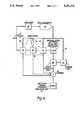
- FIG. 2is a schematic block diagram showing part of a receiver for a GSM terminal according to a first embodiment of the invention.
- FIG. 3is a schematic block diagram of part of a receiver for a GSM terminal according to an alternative embodiment of the invention.
- the receiverwhich may be incorporated in either a mobile station or a base station of a GSM system, incorporates suitable signal processing means (not shown) for processing a received signal to provide an IF signal on a line 2.
- This IF signalis modulated according to a gaussian minimum shift keying technique, and the signal is demodulated and digitized in a demodulator digitizer unit 4, following which the digital signals are equalized at equalization and processing techniques will be well known to those skilled in the art.
- IF line 2is coupled to demodulator and digitizer unit 4 by a cascaded chain 10 of three switched gain amplifiers 12,14 and 16.
- Control lines 12',14' and 16'are arranged to switch amplifiers 12,14 and 16 respectively between the condition in which they merely pass the signal without amplification (i.e. zero dB gain), and the condition in which amplifier 12 provides 32 dB of gain, amplifier 14 provides 16 dB of gain and amplifier 16 provides 8 dB of gain.
- Control lines 12',14' and 16'are coupled to a signal strength unit 20 and also to a counter 22.
- Counter 22has a start input coupled to signal strength unit 20, and a stop input coupled to a peak detector 24 which is responsive to the IF signal at the input to demodulator and digitizer unit 4. Peak detector 24 responds to say 1/4 or 1/2 of an IF waveform cycle to produce an estimate of signal strength based upon the waveform peak.
- Unit 20provides on an output line 30 a measure of signals strength detected by unit 4. This is summed at a summer 32 with the signals on lines 12',14' and 16' indicating the gain provided by chain 10 in order to provide an indication of received signal strength at received signal strength indicator (RSSI) unit 34.
- RSSIreceived signal strength indicator
- signal strength unit 20having memorized the signal strength of the IF input signal from preceding time slots, will provide signals on control lines 12',14' and 16' to provide the appropriate amount of gain to the IF signal for the resultant IF signal to be accommodated within the dynamic range of the A to D converter.
- the total received signal strengthis indicated in RSSI unit 34.
- RSSI unit 34In the traffic mode it can be assumed that the received signal level will only change slowly over large numbers of time slots. Between these slots the transmitted signals will be intended for other mobile stations, and may be at a completely different level.
- the mobile stationwill monitor base station control channel signals from adjacent base stations. These will be continuous signals of a different frequency to those frequencies used in the traffic mode signals. If the control channel signal of a base station having an unknown control channel signal strength is to be monitored, then counter 22 is actuated at the beginning of the time slot by signal strength unit 20 in order to ramp up the gain provided by the switch gained amplifiers quickly, until the signal strength as detected by peak detector 24 detects that the signal strength is within the dynamic range of the A to D converter system in unit 4 and accordingly stops counter 22.
- the setting of counter 22is memorized in unit 20 and is employed for subsequent readings.
- control channels 12,14,16each have constant carrier amplitude, there is no slot to slot level change as in the traffic mode.
- the setting of counter 22also provides a measure of the received signal strength, when combined by summer 32 with the measured amplitude of signals in unit 4 on line 30, to provide an indication of received signal strength in unit 34.
- the IF signalis applied to a logarithmic amplifier 40 which is arranged to detect the level of the IF signal.
- Amplifier 40does this within a very short space of time and can therefore detect the IF signal strength prior to received data being received at the demodulator and digitizer unit 4.
- the output of amplifier 40is converted to a digital value in flash A to D converter 42 and the digital value is fed via control lines 12',14' and 16' to control switched gain amplifiers 12,14 and 16.
- control lines 12',14' and 16'to control switched gain amplifiers 12,14 and 16.
- the signal received at unit 4has its power level measured in signal strength unit 20 and this level is summed in summer 32 together with the gain setting of amplifiers 12,14 and 16 in order to provide an accurate measurement of the received signal strength. If the measured power at signal strength unit 20 is determined to be excessive or insufficient, signals are provided via a window unit 44 to provide further gain control signals on line 46 to lines 12',14' and 16' during a window period occuring within the time slots.
- the automatic gain controlhas a relatively coarse 8 dB setting resolution. This allows precise gain setting with a small number of digital control lines, and rapid changes of gain over a wide range.
- finer resolutionmay be achieved.
- a finer automatic gain controlis, however, superimposed on the system by use of the equalizer 6. This effectively provides a further two levels of resolution. It will be appreciated however that if, for example, sufficient switched gain amplifier stages are incorporated, it may be possible to omit the equalizer.
Landscapes
- Engineering & Computer Science (AREA)
- Computer Networks & Wireless Communication (AREA)
- Signal Processing (AREA)
- Quality & Reliability (AREA)
- Physics & Mathematics (AREA)
- Electromagnetism (AREA)
- Mobile Radio Communication Systems (AREA)
- Time-Division Multiplex Systems (AREA)
- Control Of Amplification And Gain Control (AREA)
- Circuits Of Receivers In General (AREA)
Abstract
Description
Claims (7)
Applications Claiming Priority (2)
| Application Number | Priority Date | Filing Date | Title |
|---|---|---|---|
| GB898915172AGB8915172D0 (en) | 1989-07-01 | 1989-07-01 | Receiver gain control for radio telephone system |
| GB8915172 | 1989-07-01 |
Publications (1)
| Publication Number | Publication Date |
|---|---|
| US5251216Atrue US5251216A (en) | 1993-10-05 |
Family
ID=10659408
Family Applications (1)
| Application Number | Title | Priority Date | Filing Date |
|---|---|---|---|
| US07/543,470Expired - LifetimeUS5251216A (en) | 1989-07-01 | 1990-06-26 | Receiver gain control for radio telephone system |
Country Status (6)
| Country | Link |
|---|---|
| US (1) | US5251216A (en) |
| EP (1) | EP0411756B1 (en) |
| JP (1) | JPH0342925A (en) |
| AU (1) | AU630206B2 (en) |
| DE (1) | DE69015281T2 (en) |
| GB (2) | GB8915172D0 (en) |
Cited By (11)
| Publication number | Priority date | Publication date | Assignee | Title |
|---|---|---|---|---|
| US5375123A (en)* | 1993-02-05 | 1994-12-20 | Telefonakitebolaget L. M. Ericsson | Allocation of channels using interference estimation |
| US5493712A (en)* | 1994-03-23 | 1996-02-20 | At&T Corp. | Fast AGC for TDMA radio systems |
| WO1996010868A1 (en)* | 1994-10-03 | 1996-04-11 | Telefonaktiebolaget Lm Ericsson | Method and arrangement in a transmission system |
| US5884152A (en)* | 1995-01-31 | 1999-03-16 | Nec Corporation | Automatic gain control with constant gain coefficient during mobile's receive time slot |
| US20010048727A1 (en)* | 2000-01-10 | 2001-12-06 | Schmutz Thomas R. | Method and apparatus for automatic gain control on a time slot by time slot basis |
| US20020048267A1 (en)* | 2000-10-19 | 2002-04-25 | Interdigital Technology Corporation | Selectively activated AGC signal measurement unit |
| US6385456B2 (en)* | 1996-01-04 | 2002-05-07 | Sony Corporation | Method and system of transmitting data in a cellular radio system |
| WO2004034615A1 (en)* | 2002-10-11 | 2004-04-22 | Navini Networks, Inc | Method and system for interference assessment and reduction in a wireless communication system |
| US6925072B1 (en)* | 2000-08-03 | 2005-08-02 | Ericsson Inc. | System and method for transmitting control information between a control unit and at least one sub-unit |
| US20050260964A1 (en)* | 2002-11-28 | 2005-11-24 | Elmar Wagner | Amplifier assembly, receiver comprising said assembly and method for operating a programmable amplifier |
| DE102011081245A1 (en)* | 2011-03-31 | 2012-10-04 | Rohde & Schwarz Gmbh & Co. Kg | Device and method for fixing a gain or damping factor |
Families Citing this family (14)
| Publication number | Priority date | Publication date | Assignee | Title |
|---|---|---|---|---|
| GB2250402B (en)* | 1990-09-28 | 1995-06-21 | Matsushita Electric Industrial Co Ltd | Power saving apparatus of a radiotelephone |
| FI87287C (en)* | 1991-01-15 | 1992-12-10 | Nokia Mobile Phones Ltd | FOERSTAERKNINGSREGLERING AV EN AGC-FOERSTAERKARE I ETT PAO TIDSMULTIPLEXERING BASERAT RADIOTELEFONSYSTEM |
| JP2730347B2 (en)* | 1991-10-09 | 1998-03-25 | 松下電器産業株式会社 | Automatic receiver gain control method |
| EP0569688A1 (en)* | 1992-04-29 | 1993-11-18 | Hagenuk Telecom GmbH | Method and apparatus for fading compensation for TDMA-receivers |
| EP0573108B1 (en)* | 1992-06-03 | 2000-03-08 | Koninklijke Philips Electronics N.V. | Automatic cable attenuation compensation system |
| US5312991A (en)* | 1992-06-09 | 1994-05-17 | Mallinckrodt Specialty Chemicals Company | Surfactant improvement for para-aminophenol process |
| US5408696A (en)* | 1992-12-11 | 1995-04-18 | Telefonaktiebolaget L M Ericsson | Method and apparatus for correcting a radio signal strength information signal |
| FI96554C (en)* | 1993-02-05 | 1996-07-10 | Nokia Mobile Phones Ltd | Time multiplexed cellular radio telephone system and radio telephone for it |
| US5548594A (en)* | 1993-12-28 | 1996-08-20 | Nec Corporation | Compact AGC circuit with stable characteristics |
| GB2286305B (en)* | 1994-01-29 | 1998-12-02 | Motorola Ltd | Power amplifier for radio transmitter and dual mode remote radio |
| CA2175860C (en)* | 1995-06-02 | 2001-03-27 | Randall Wayne Rich | Apparatus and method for optimizing the quality of a received signal in a radio receiver |
| US5524009A (en)* | 1995-06-07 | 1996-06-04 | Nokia Mobile Phones Ltd. | Fast AGC setting using RSS (I) measurement procedure |
| US6563891B1 (en)* | 1998-11-24 | 2003-05-13 | Telefonaktiebolaget L M Ericsson (Publ) | Automatic gain control for slotted mode operation |
| FI111203B (en) | 2001-03-05 | 2003-06-13 | Nokia Corp | Determination of a reference value for AGC control of a receiver on a general packet control channel |
Citations (10)
| Publication number | Priority date | Publication date | Assignee | Title |
|---|---|---|---|---|
| DE2061744A1 (en)* | 1969-12-23 | 1971-07-01 | Philips Nv | Device for transmitting information when the frequency changes |
| US4330859A (en)* | 1978-09-25 | 1982-05-18 | Nippon Electric Co., Ltd. | Automatic gain control circuit in multi-direction time division multiplex communication system |
| US4577310A (en)* | 1984-05-16 | 1986-03-18 | Tie/Communications, Inc. | Station interface for digital electronic telephone switching system having centralized digital audio processor |
| EP0192061A1 (en)* | 1985-01-22 | 1986-08-27 | Alcatel Transmission Par Faisceaux Hertziens A.T.F.H. | Device for automatic gain control in a TDMA receiver |
| US4635103A (en)* | 1984-12-03 | 1987-01-06 | Rca Corporation | Phase locked loop system incorporating automatic gain control |
| US4656630A (en)* | 1984-01-10 | 1987-04-07 | Fujitsu Limited | Automatic gain control circuit |
| EP0325252A2 (en)* | 1988-01-19 | 1989-07-26 | Nec Corporation | Gain control circuit for amplifier having stepwise variable gain |
| US4930126A (en)* | 1989-06-05 | 1990-05-29 | Motorola, Inc. | Time division multiplex system suited for burst analog transmission |
| US5029162A (en)* | 1990-03-06 | 1991-07-02 | Confertech International | Automatic gain control using root-mean-square circuitry in a digital domain conference bridge for a telephone network |
| US5042082A (en)* | 1989-06-26 | 1991-08-20 | Telefonaktiebolaget L. M. Ericsson | Mobile assisted handoff |
Family Cites Families (3)
| Publication number | Priority date | Publication date | Assignee | Title |
|---|---|---|---|---|
| US4581725A (en)* | 1982-07-21 | 1986-04-08 | Mobil Oil Corporation | Method and system for gain selection |
| EP0330501A3 (en)* | 1988-02-25 | 1991-03-27 | Mitsubishi Rayon Co., Ltd. | Measurement arrangement with automatic gain control circuit |
| IE64560B1 (en)* | 1988-11-30 | 1995-08-23 | Motorola Inc | Digital automatic gain control |
- 1989
- 1989-07-01GBGB898915172Apatent/GB8915172D0/enactivePending
- 1990
- 1990-06-15GBGB9013399Apatent/GB2233846B/ennot_activeExpired - Fee Related
- 1990-06-15DEDE69015281Tpatent/DE69015281T2/ennot_activeExpired - Fee Related
- 1990-06-15EPEP90306570Apatent/EP0411756B1/ennot_activeExpired - Lifetime
- 1990-06-26USUS07/543,470patent/US5251216A/ennot_activeExpired - Lifetime
- 1990-06-29JPJP2170347Apatent/JPH0342925A/enactivePending
- 1990-07-02AUAU58069/90Apatent/AU630206B2/ennot_activeCeased
Patent Citations (10)
| Publication number | Priority date | Publication date | Assignee | Title |
|---|---|---|---|---|
| DE2061744A1 (en)* | 1969-12-23 | 1971-07-01 | Philips Nv | Device for transmitting information when the frequency changes |
| US4330859A (en)* | 1978-09-25 | 1982-05-18 | Nippon Electric Co., Ltd. | Automatic gain control circuit in multi-direction time division multiplex communication system |
| US4656630A (en)* | 1984-01-10 | 1987-04-07 | Fujitsu Limited | Automatic gain control circuit |
| US4577310A (en)* | 1984-05-16 | 1986-03-18 | Tie/Communications, Inc. | Station interface for digital electronic telephone switching system having centralized digital audio processor |
| US4635103A (en)* | 1984-12-03 | 1987-01-06 | Rca Corporation | Phase locked loop system incorporating automatic gain control |
| EP0192061A1 (en)* | 1985-01-22 | 1986-08-27 | Alcatel Transmission Par Faisceaux Hertziens A.T.F.H. | Device for automatic gain control in a TDMA receiver |
| EP0325252A2 (en)* | 1988-01-19 | 1989-07-26 | Nec Corporation | Gain control circuit for amplifier having stepwise variable gain |
| US4930126A (en)* | 1989-06-05 | 1990-05-29 | Motorola, Inc. | Time division multiplex system suited for burst analog transmission |
| US5042082A (en)* | 1989-06-26 | 1991-08-20 | Telefonaktiebolaget L. M. Ericsson | Mobile assisted handoff |
| US5029162A (en)* | 1990-03-06 | 1991-07-02 | Confertech International | Automatic gain control using root-mean-square circuitry in a digital domain conference bridge for a telephone network |
Non-Patent Citations (4)
| Title |
|---|
| 37th IEEE Vehic. Techn. Conference 1987 (NY) pp. 293 299 Radio Test Performance of a Narrowband TDMA System (Stjernvall et al.) p. 294, line 14 line 18.* |
| 37th IEEE Vehic. Techn. Conference 1987 (NY) pp. 293-299 Radio Test Performance of a Narrowband TDMA System (Stjernvall et al.) p. 294, line 14-line 18. |
| Patent Abstracts of Japan, vol. 10, No. 145 (E 407) (2202) 28 May 1986 and JP A 61 005 610 (Mitsubishi) 11 Jan. 1986.* |
| Patent Abstracts of Japan, vol. 10, No. 145 (E-407) (2202) 28 May 1986 and JP-A-61 005 610 (Mitsubishi) 11 Jan. 1986. |
Cited By (18)
| Publication number | Priority date | Publication date | Assignee | Title |
|---|---|---|---|---|
| US5375123A (en)* | 1993-02-05 | 1994-12-20 | Telefonakitebolaget L. M. Ericsson | Allocation of channels using interference estimation |
| US5493712A (en)* | 1994-03-23 | 1996-02-20 | At&T Corp. | Fast AGC for TDMA radio systems |
| WO1996010868A1 (en)* | 1994-10-03 | 1996-04-11 | Telefonaktiebolaget Lm Ericsson | Method and arrangement in a transmission system |
| AU697709B2 (en)* | 1994-10-03 | 1998-10-15 | Telefonaktiebolaget Lm Ericsson (Publ) | Method and arrangement in a transmission system |
| US6035001A (en)* | 1994-10-03 | 2000-03-07 | Telefonaktiebolaget Lm Ericsson | Method and arrangement in a transmission system |
| CN1092866C (en)* | 1994-10-03 | 2002-10-16 | 艾利森电话股份有限公司 | Method and arrangement in a transmission system |
| US5884152A (en)* | 1995-01-31 | 1999-03-16 | Nec Corporation | Automatic gain control with constant gain coefficient during mobile's receive time slot |
| US6385456B2 (en)* | 1996-01-04 | 2002-05-07 | Sony Corporation | Method and system of transmitting data in a cellular radio system |
| US20010048727A1 (en)* | 2000-01-10 | 2001-12-06 | Schmutz Thomas R. | Method and apparatus for automatic gain control on a time slot by time slot basis |
| US6925072B1 (en)* | 2000-08-03 | 2005-08-02 | Ericsson Inc. | System and method for transmitting control information between a control unit and at least one sub-unit |
| US20020048267A1 (en)* | 2000-10-19 | 2002-04-25 | Interdigital Technology Corporation | Selectively activated AGC signal measurement unit |
| US7085255B2 (en)* | 2000-10-19 | 2006-08-01 | Interdigital Technology Corporation | Selectively activated AGC signal measurement unit |
| WO2004034615A1 (en)* | 2002-10-11 | 2004-04-22 | Navini Networks, Inc | Method and system for interference assessment and reduction in a wireless communication system |
| US7068977B1 (en)* | 2002-10-11 | 2006-06-27 | Navini Networks, Inc. | Method and system for interference assessment and reduction in a wireless communication system |
| US20050260964A1 (en)* | 2002-11-28 | 2005-11-24 | Elmar Wagner | Amplifier assembly, receiver comprising said assembly and method for operating a programmable amplifier |
| US7734267B2 (en)* | 2002-11-28 | 2010-06-08 | Infineon Technologies Ag | Amplifier assembly, receiver comprising said assembly and method for operating a programmable amplifier |
| DE102011081245A1 (en)* | 2011-03-31 | 2012-10-04 | Rohde & Schwarz Gmbh & Co. Kg | Device and method for fixing a gain or damping factor |
| US9048804B2 (en) | 2011-03-31 | 2015-06-02 | Rohde & Schwarz Gmbh & Co. Kg | Device and a method for fixing a gain or attenuation factor |
Also Published As
| Publication number | Publication date |
|---|---|
| AU630206B2 (en) | 1992-10-22 |
| EP0411756A2 (en) | 1991-02-06 |
| AU5806990A (en) | 1991-01-03 |
| GB9013399D0 (en) | 1990-08-08 |
| JPH0342925A (en) | 1991-02-25 |
| GB2233846B (en) | 1994-07-13 |
| EP0411756A3 (en) | 1992-01-02 |
| GB8915172D0 (en) | 1989-08-23 |
| GB2233846A (en) | 1991-01-16 |
| EP0411756B1 (en) | 1994-12-21 |
| DE69015281T2 (en) | 1995-07-27 |
| DE69015281D1 (en) | 1995-02-02 |
Similar Documents
| Publication | Publication Date | Title |
|---|---|---|
| US5251216A (en) | Receiver gain control for radio telephone system | |
| US5067171A (en) | Method and apparatus for hand-off of call in progress | |
| US5239541A (en) | Antenna selection diversity reception apparatus | |
| US5331638A (en) | Gain control in a TDMA radio-telephone system | |
| US6330433B1 (en) | Antenna selection control circuitry | |
| JP2532784B2 (en) | Method for selecting a dedicated control channel and its associated base station in a cellular mobile radio system | |
| JPS61240725A (en) | Method and apparatus for measuring quality of wireless transmission channel | |
| JPH0555976A (en) | Receiver for mobile telephone system | |
| EP1689096A2 (en) | Transmitter in a data transmission system and corresponding method | |
| JP2001358606A (en) | Time division multiplex radio equipment | |
| JPH11187463A (en) | Mobile radio receiver | |
| CA2247241A1 (en) | Method and system for determining the integrity of a received signal | |
| US5475709A (en) | Adjacent and alternate channels power measurement apparatus | |
| US6192226B1 (en) | Carrier squelch processing system and apparatus | |
| JP2885267B2 (en) | Digitally modulated signal receiver | |
| US5152009A (en) | Diversity reception control circuit | |
| JPH1093647A (en) | Receiver having DC offset removal function and communication system using the same | |
| JP3798596B2 (en) | Signal detection device | |
| JP2871634B2 (en) | Burst signal demodulator | |
| KR100186598B1 (en) | Method for measuring receiving strength of radio signal | |
| JP3324303B2 (en) | Received signal level detection circuit | |
| JP2712853B2 (en) | Empty channel detection method | |
| KR100219283B1 (en) | Apparatus for estimating maximum communication capacity in cdma bs system | |
| JPH0897766A (en) | Receiver circuit | |
| JPH09238124A (en) | Diversity receiving method of high-speed data transmission system |
Legal Events
| Date | Code | Title | Description |
|---|---|---|---|
| AS | Assignment | Owner name:ORBITEL MOBILE COMMUNICATIONS LIMITED, ENGLAND Free format text:ASSIGNMENT OF ASSIGNORS INTEREST.;ASSIGNORS:MARSHALL, KEITH;BRISTOW, ROBERT O.;CHEER, ANDREW P.;REEL/FRAME:005353/0474 Effective date:19900613 | |
| AS | Assignment | Owner name:ORBITEL MOBILE COMMUNICATIONS LIMITED, ENGLAND Free format text:ASSIGNMENT OF ASSIGNORS INTEREST;ASSIGNOR:ORBITEL MOBIL COMMUNICATIONS (1995) LIMITED;REEL/FRAME:007662/0664 Effective date:19950908 Owner name:ORBITEL MOBILE COMMUNICATIONS (1995) LIMITED, ENGL Free format text:CHANGE OF NAME EFFECTIVE 4-1-95;ASSIGNOR:ORBITEL MOBILE COMMUNICATIONS LIMITED;REEL/FRAME:007639/0567 Effective date:19950915 | |
| FPAY | Fee payment | Year of fee payment:4 | |
| AS | Assignment | Owner name:ERICSSON OMC LIMITED, UNITED KINGDOM Free format text:ASSIGNMENT OF ASSIGNORS INTEREST;ASSIGNOR:ORBITEL MOBILE COMMUNICATIONS LIMITED;REEL/FRAME:009146/0734 Effective date:19971208 | |
| FPAY | Fee payment | Year of fee payment:8 | |
| REMI | Maintenance fee reminder mailed | ||
| REIN | Reinstatement after maintenance fee payment confirmed | ||
| FP | Lapsed due to failure to pay maintenance fee | Effective date:20051005 | |
| FEPP | Fee payment procedure | Free format text:PETITION RELATED TO MAINTENANCE FEES FILED (ORIGINAL EVENT CODE: PMFP); ENTITY STATUS OF PATENT OWNER: LARGE ENTITY | |
| FEPP | Fee payment procedure | Free format text:PETITION RELATED TO MAINTENANCE FEES GRANTED (ORIGINAL EVENT CODE: PMFG); ENTITY STATUS OF PATENT OWNER: LARGE ENTITY | |
| FPAY | Fee payment | Year of fee payment:12 | |
| SULP | Surcharge for late payment | ||
| PRDP | Patent reinstated due to the acceptance of a late maintenance fee | Effective date:20060918 | |
| PRDP | Patent reinstated due to the acceptance of a late maintenance fee | Effective date:20060918 | |
| STCF | Information on status: patent grant | Free format text:PATENTED CASE |