US5250057A - Anastomotic device - Google Patents
Anastomotic deviceDownload PDFInfo
- Publication number
- US5250057A US5250057AUS07/902,210US90221092AUS5250057AUS 5250057 AUS5250057 AUS 5250057AUS 90221092 AUS90221092 AUS 90221092AUS 5250057 AUS5250057 AUS 5250057A
- Authority
- US
- United States
- Prior art keywords
- wall
- pins
- pin
- opposed
- tubular element
- Prior art date
- Legal status (The legal status is an assumption and is not a legal conclusion. Google has not performed a legal analysis and makes no representation as to the accuracy of the status listed.)
- Expired - Fee Related
Links
- 230000003292diminished effectEffects0.000claimsdescription7
- 230000013011matingEffects0.000claimsdescription5
- 210000001035gastrointestinal tractAnatomy0.000claimsdescription2
- 230000014759maintenance of locationEffects0.000claimsdescription2
- 230000000694effectsEffects0.000description5
- 238000004519manufacturing processMethods0.000description3
- 238000004090dissolutionMethods0.000description2
- 230000000968intestinal effectEffects0.000description2
- 239000000463materialSubstances0.000description2
- 238000001356surgical procedureMethods0.000description2
- XZMCDFZZKTWFGF-UHFFFAOYSA-NCyanamideChemical compoundNC#NXZMCDFZZKTWFGF-UHFFFAOYSA-N0.000description1
- 230000003872anastomosisEffects0.000description1
- 230000017531blood circulationEffects0.000description1
- 230000002708enhancing effectEffects0.000description1
- 238000013467fragmentationMethods0.000description1
- 238000006062fragmentation reactionMethods0.000description1
- 210000005095gastrointestinal systemAnatomy0.000description1
- 230000035876healingEffects0.000description1
- 210000000936intestineAnatomy0.000description1
- 238000012986modificationMethods0.000description1
- 230000004048modificationEffects0.000description1
- 230000017074necrotic cell deathEffects0.000description1
- 230000002035prolonged effectEffects0.000description1
- 238000002271resectionMethods0.000description1
Images
Classifications
- A—HUMAN NECESSITIES
- A61—MEDICAL OR VETERINARY SCIENCE; HYGIENE
- A61B—DIAGNOSIS; SURGERY; IDENTIFICATION
- A61B17/00—Surgical instruments, devices or methods
- A61B17/11—Surgical instruments, devices or methods for performing anastomosis; Buttons for anastomosis
- A—HUMAN NECESSITIES
- A61—MEDICAL OR VETERINARY SCIENCE; HYGIENE
- A61B—DIAGNOSIS; SURGERY; IDENTIFICATION
- A61B17/00—Surgical instruments, devices or methods
- A61B17/11—Surgical instruments, devices or methods for performing anastomosis; Buttons for anastomosis
- A61B2017/1107—Surgical instruments, devices or methods for performing anastomosis; Buttons for anastomosis for blood vessels
- A—HUMAN NECESSITIES
- A61—MEDICAL OR VETERINARY SCIENCE; HYGIENE
- A61B—DIAGNOSIS; SURGERY; IDENTIFICATION
- A61B17/00—Surgical instruments, devices or methods
- A61B17/11—Surgical instruments, devices or methods for performing anastomosis; Buttons for anastomosis
- A61B2017/1132—End-to-end connections
Definitions
- the present inventionrelates to the surgical joining of tubular structures and especially in the gastro-intestinal system after resection.
- the devicecomprises a clamping means that requires a relatively large contact area with the tissue or body structure;
- the devicerequires eversion of, and clamping pressure on, the anastomosed parts that may be causative of necrosis or at least result in severely diminished blood flow and a prolonged period for healing;
- the deviceis of undue size and weight
- the deviceis awkward to use, in contradistinction to efficient surgical procedure.
- the deviceis relatively sophisticated with respect to manufacture and use.
- An anastomotic devicethat is particularly directed to surgical joining of the intestine is the VATRAC® Bar produced by the Davis & Geck Medical Device Division of the American Cyanamid Company. This device is relatively large, requires sophisticated handling, partial eversion of the intestinal parts and clamping thereof.
- the present inventionis directed to an improved surgical device that is especially useful for intestinal joinder and is: mechanically simple and inexpensive to manufacture; easy to use to thus facilitate efficient surgical procedure; provides for minimal device-to-body structure area of contact; does not require eversion or clamping of the lumen walls; provides a telescopic-friction-interlock of annular parts which results in a simplified structure of reduced mass and which parts are each provided with spaced retaining pins that are each adapted to effect anastomosis by impaling a respective first lumen wall, extend therethrough in the general luminal axis direction and subsequently impale an opposed lumen wall to effect surgical joinder and the device is disposed within the lumen.
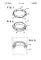
- FIG. 1is a perspective view of the outer annulus of the device.
- FIG. 2is a perspective of the inner annulus.
- FIG. 3is a sectional, elevational view of the device in operative association of its parts and functional with respect to anastomosed structure shown in broken lines, parts of retaining pins being omitted for clarity.
- annular member 10having an outer wall portion 12 of diminished thickness and a series of spaced retaining pins 14 that each project outwardly at about 10° from the outer end portion of wall section 16 of said outer wall and extend to beyond the shoulder 18 that terminates the diminished wall portion 12.
- FIG. 1discloses an annular member 20 having an inner wall 22, an outer wall 24, and an end wall 26.
- the wall portion 12is dimensioned to be telescopically received and frictionally locked in annulus 20, with said end wall 26 abutting shoulder 18 and the outer surfaces 16, 24 presenting in effect a continuous wall of generally uniform diameter; but for said retaining pins 14, and corresponding pins 28 that are integral with annulus 20, project outwardly at about 10° from an end section of wall 24 and extend beyond the transverse plane of mating of said end wall 26 and shoulder 18.
- FIG. 3discloses the novel and improved device in functional relationship with anastomosed lumens 30, 32 (shown in broken lines), whose intima are opposed and aligned. For purposes of clarity, not all retainer pin structure is disclosed, and the parts are dimensionally exaggerated.
- the annuliare arranged for operative association so that the axially opposed retaining pins are in alternate relationship with one another, and a separate annulus of the device, at its non-piercing end, is inserted into a respective one of the lumens until the pins reach the desired point of impalement entry.
- the respective lumenis then retracted to effect impalement on the associated retaining pins to the extent that each lumen wall end associates and aligns with its respective end wall 18 or 26.
- the retaining pinslie within the respective lumen walls except for end portions which extend through the respective ends of the lumen walls and are adapted to extend into and within the opposed lumen wall.
- the annuliare then telescopically joined whereby to be frictionally locked and the free ends of the retaining pins entered into the opposed lumen. Means may be provided to either visually or mechanically effect such alternate disposition of the retaining pins.
- the retaining pinsmay vary in configuration with a view to lumen size and to enhancing lumen retention, and the number of pins utilized may vary in accordance with specific need.
- the materials of fabricationare flexible, compatible with that of the human body, biodegradable and biofragmentable and may be treated or coated in order to control the time of material dissolution and fragmentation, as is known in the art.
- dissolutionis not a problem since the device is primarily disposed within the intestinal tract and will be naturally eliminated.
- the anastomotic embodiment of the invention described and illustratedis of relatively small mass, simplistic in structure and mechanical association, is significantly of minimal radial extension and, in use, requires no lumen wall eversion or distortion.
Landscapes
- Health & Medical Sciences (AREA)
- Life Sciences & Earth Sciences (AREA)
- Surgery (AREA)
- Heart & Thoracic Surgery (AREA)
- Engineering & Computer Science (AREA)
- Biomedical Technology (AREA)
- Nuclear Medicine, Radiotherapy & Molecular Imaging (AREA)
- Medical Informatics (AREA)
- Molecular Biology (AREA)
- Animal Behavior & Ethology (AREA)
- General Health & Medical Sciences (AREA)
- Public Health (AREA)
- Veterinary Medicine (AREA)
- Surgical Instruments (AREA)
Abstract
Description
Claims (6)
Priority Applications (2)
| Application Number | Priority Date | Filing Date | Title |
|---|---|---|---|
| US07/902,210US5250057A (en) | 1989-01-26 | 1992-06-22 | Anastomotic device |
| US08/037,399US5336233A (en) | 1989-01-26 | 1993-03-26 | Anastomotic device |
Applications Claiming Priority (5)
| Application Number | Priority Date | Filing Date | Title |
|---|---|---|---|
| US07/303,326US4930502A (en) | 1989-01-26 | 1989-01-26 | Anastomosis device |
| US07/472,209US4997439A (en) | 1989-01-26 | 1990-01-26 | Surgical closure or anastomotic device |
| US07/629,608US5089008A (en) | 1989-01-26 | 1990-12-18 | Surgical closure means for anastomotic device |
| US07/735,950US5123908A (en) | 1989-01-26 | 1991-07-25 | Anastomotic device |
| US07/902,210US5250057A (en) | 1989-01-26 | 1992-06-22 | Anastomotic device |
Related Parent Applications (1)
| Application Number | Title | Priority Date | Filing Date |
|---|---|---|---|
| US07/735,950Continuation-In-PartUS5123908A (en) | 1989-01-26 | 1991-07-25 | Anastomotic device |
Related Child Applications (1)
| Application Number | Title | Priority Date | Filing Date |
|---|---|---|---|
| US08/037,399Continuation-In-PartUS5336233A (en) | 1989-01-26 | 1993-03-26 | Anastomotic device |
Publications (1)
| Publication Number | Publication Date |
|---|---|
| US5250057Atrue US5250057A (en) | 1993-10-05 |
Family
ID=27540890
Family Applications (1)
| Application Number | Title | Priority Date | Filing Date |
|---|---|---|---|
| US07/902,210Expired - Fee RelatedUS5250057A (en) | 1989-01-26 | 1992-06-22 | Anastomotic device |
Country Status (1)
| Country | Link |
|---|---|
| US (1) | US5250057A (en) |
Cited By (21)
| Publication number | Priority date | Publication date | Assignee | Title |
|---|---|---|---|---|
| US5690656A (en)* | 1995-06-27 | 1997-11-25 | Cook Incorporated | Method and apparatus for creating abdominal visceral anastomoses |
| US5868763A (en)* | 1996-09-16 | 1999-02-09 | Guidant Corporation | Means and methods for performing an anastomosis |
| US6488692B1 (en) | 1996-09-16 | 2002-12-03 | Origin Medsystems, Inc. | Access and cannulation device and method for rapidly placing same and for rapidly closing same in minimally invasive surgery |
| US6565581B1 (en) | 1996-09-16 | 2003-05-20 | Origin Medsystems, Inc. | Apparatus and method for performing an anastomosis |
| US6629988B2 (en) | 2001-08-28 | 2003-10-07 | Ethicon, Inc. | Composite staple for completing an anastomosis |
| US6811555B1 (en) | 1996-09-16 | 2004-11-02 | Origin Medsystems, Inc. | Method and apparatus for performing anastomosis with eversion of tissue edges and joining of exposed intima of the everted tissue |
| US6890338B1 (en) | 2001-02-27 | 2005-05-10 | Origin Medsystems, Inc. | Method and apparatus for performing anastomosis using ring having tines with weak sections |
| US20050149073A1 (en)* | 2003-12-17 | 2005-07-07 | Arani Djavad T. | Mechanisms and methods used in the anastomosis of biological conduits |
| US7192400B2 (en) | 2002-10-24 | 2007-03-20 | Synovis Life Technologies, Inc. | Device and method for vascular monitoring |
| US20070250082A1 (en)* | 2004-07-22 | 2007-10-25 | Kansoul Hassan A | Anastomosis Device and Method |
| US20080200938A1 (en)* | 2007-02-15 | 2008-08-21 | Cook Vascular Incorporated | Probe coupler assembly |
| US20090012543A1 (en)* | 2006-01-12 | 2009-01-08 | Prozeo Vascular Implant Ab | Device and method for anastomosis |
| USD660960S1 (en)* | 2007-07-13 | 2012-05-29 | Carponovum Ab | Rigid parts of an anastomosis device |
| USD783814S1 (en)* | 2013-12-09 | 2017-04-11 | B. Braun Medical Sas | Adapter for flatus release |
| USD796029S1 (en) | 2013-12-09 | 2017-08-29 | B. Braun Medical Sas | Colostomy appliance |
| US9883964B2 (en) | 2012-05-10 | 2018-02-06 | B. Braun Medical Sas | Ostomy appliance |
| US10537461B2 (en) | 2009-07-14 | 2020-01-21 | B. Braun Medical Sas | Disposable ostomy assemblies |
| US11291579B2 (en) | 2013-05-09 | 2022-04-05 | B. Braun Medical Sas | Gas filter and release for ostomy appliance |
| US20220273311A1 (en)* | 2019-05-07 | 2022-09-01 | Easyflomicro Inc. | Apparatuses for anastomosis of tubular vessels and related methods |
| USD1012280S1 (en) | 2018-11-30 | 2024-01-23 | B. Braun Medical Sas | Ostomy device assembly |
| WO2024102848A1 (en)* | 2022-11-09 | 2024-05-16 | University Of Utah Research Foundation | Vascular anastomosis system |
Citations (4)
| Publication number | Priority date | Publication date | Assignee | Title |
|---|---|---|---|---|
| US3990434A (en)* | 1975-02-18 | 1976-11-09 | The United States Of America As Represented By The Department Of Health, Education And Welfare | Reversible intravasal occlusive device |
| US4523592A (en)* | 1983-04-25 | 1985-06-18 | Rollin K. Daniel P.S.C. | Anastomotic coupling means capable of end-to-end and end-to-side anastomosis |
| US4693249A (en)* | 1986-01-10 | 1987-09-15 | Schenck Robert R | Anastomosis device and method |
| US4747407A (en)* | 1985-09-03 | 1988-05-31 | The Field Surgery Research Department of the Third Military Medical University | Blood vessel anastomat |
- 1992
- 1992-06-22USUS07/902,210patent/US5250057A/ennot_activeExpired - Fee Related
Patent Citations (4)
| Publication number | Priority date | Publication date | Assignee | Title |
|---|---|---|---|---|
| US3990434A (en)* | 1975-02-18 | 1976-11-09 | The United States Of America As Represented By The Department Of Health, Education And Welfare | Reversible intravasal occlusive device |
| US4523592A (en)* | 1983-04-25 | 1985-06-18 | Rollin K. Daniel P.S.C. | Anastomotic coupling means capable of end-to-end and end-to-side anastomosis |
| US4747407A (en)* | 1985-09-03 | 1988-05-31 | The Field Surgery Research Department of the Third Military Medical University | Blood vessel anastomat |
| US4693249A (en)* | 1986-01-10 | 1987-09-15 | Schenck Robert R | Anastomosis device and method |
Cited By (37)
| Publication number | Priority date | Publication date | Assignee | Title |
|---|---|---|---|---|
| US5690656A (en)* | 1995-06-27 | 1997-11-25 | Cook Incorporated | Method and apparatus for creating abdominal visceral anastomoses |
| US6811555B1 (en) | 1996-09-16 | 2004-11-02 | Origin Medsystems, Inc. | Method and apparatus for performing anastomosis with eversion of tissue edges and joining of exposed intima of the everted tissue |
| US20040220597A1 (en)* | 1996-09-16 | 2004-11-04 | Willis Geoffrey H. | Method and apparatus for performing anastomosis with eversion of tissue edges and joining of exposed intima of the everted tissue |
| US6241742B1 (en) | 1996-09-16 | 2001-06-05 | Origin Medsystems, Inc. | Means and method for performing an anastomosis |
| US7497865B2 (en) | 1996-09-16 | 2009-03-03 | Maquet Cardiovascular, Llc | Method and apparatus for performing anastomosis with eversion of tissue edges and joining of exposed intima of the everted tissue |
| US6488692B1 (en) | 1996-09-16 | 2002-12-03 | Origin Medsystems, Inc. | Access and cannulation device and method for rapidly placing same and for rapidly closing same in minimally invasive surgery |
| US6565581B1 (en) | 1996-09-16 | 2003-05-20 | Origin Medsystems, Inc. | Apparatus and method for performing an anastomosis |
| US5868763A (en)* | 1996-09-16 | 1999-02-09 | Guidant Corporation | Means and methods for performing an anastomosis |
| US6884251B2 (en) | 1996-09-16 | 2005-04-26 | Origin Medsystems, Inc. | Apparatus and method for performing an anastomosis |
| US6190397B1 (en) | 1996-09-16 | 2001-02-20 | Origin Medsystems, Inc. | Means and method for performing an anastomosis |
| US6652543B2 (en) | 1996-09-16 | 2003-11-25 | Origin Medsystems, Inc. | Means and method for performing an anastomosis |
| US6254617B1 (en) | 1996-09-16 | 2001-07-03 | Origin Medsystems, Inc. | Means and method for performing an anastomosis |
| US6890338B1 (en) | 2001-02-27 | 2005-05-10 | Origin Medsystems, Inc. | Method and apparatus for performing anastomosis using ring having tines with weak sections |
| US20030216778A1 (en)* | 2001-08-28 | 2003-11-20 | Weadock Kevin S | Composite staple for completing an anastomosis |
| US7220272B2 (en)* | 2001-08-28 | 2007-05-22 | Ethicon, Inc. | Composite staple and method for using same |
| US6629988B2 (en) | 2001-08-28 | 2003-10-07 | Ethicon, Inc. | Composite staple for completing an anastomosis |
| US7192400B2 (en) | 2002-10-24 | 2007-03-20 | Synovis Life Technologies, Inc. | Device and method for vascular monitoring |
| US20050149073A1 (en)* | 2003-12-17 | 2005-07-07 | Arani Djavad T. | Mechanisms and methods used in the anastomosis of biological conduits |
| US20070250082A1 (en)* | 2004-07-22 | 2007-10-25 | Kansoul Hassan A | Anastomosis Device and Method |
| US20090012543A1 (en)* | 2006-01-12 | 2009-01-08 | Prozeo Vascular Implant Ab | Device and method for anastomosis |
| US20080200938A1 (en)* | 2007-02-15 | 2008-08-21 | Cook Vascular Incorporated | Probe coupler assembly |
| US8202284B2 (en)* | 2007-02-15 | 2012-06-19 | Cook Medical Technologies Llc | Probe coupler assembly |
| US20120253368A1 (en)* | 2007-02-15 | 2012-10-04 | Cook Medical Technologies Llc | Probe coupler assembly |
| US8617191B2 (en)* | 2007-02-15 | 2013-12-31 | Cook Medical Technologies Llc | Probe coupler assembly |
| USD660960S1 (en)* | 2007-07-13 | 2012-05-29 | Carponovum Ab | Rigid parts of an anastomosis device |
| USD687145S1 (en) | 2007-07-13 | 2013-07-30 | Carponovum Ab | Male part of an anastomosis device |
| USD687144S1 (en) | 2007-07-13 | 2013-07-30 | Carpnovum AB | Female part of an anastomosis device |
| US10537461B2 (en) | 2009-07-14 | 2020-01-21 | B. Braun Medical Sas | Disposable ostomy assemblies |
| US9883964B2 (en) | 2012-05-10 | 2018-02-06 | B. Braun Medical Sas | Ostomy appliance |
| US10524953B2 (en) | 2012-05-10 | 2020-01-07 | B. Braun Medical Sas | Compact ostomy appliance |
| US11291579B2 (en) | 2013-05-09 | 2022-04-05 | B. Braun Medical Sas | Gas filter and release for ostomy appliance |
| USD796029S1 (en) | 2013-12-09 | 2017-08-29 | B. Braun Medical Sas | Colostomy appliance |
| USD783814S1 (en)* | 2013-12-09 | 2017-04-11 | B. Braun Medical Sas | Adapter for flatus release |
| USD1012280S1 (en) | 2018-11-30 | 2024-01-23 | B. Braun Medical Sas | Ostomy device assembly |
| US20220273311A1 (en)* | 2019-05-07 | 2022-09-01 | Easyflomicro Inc. | Apparatuses for anastomosis of tubular vessels and related methods |
| US11751876B2 (en)* | 2019-05-07 | 2023-09-12 | Easyflomicro Inc. | Apparatuses for anastomosis of tubular vessels and related methods |
| WO2024102848A1 (en)* | 2022-11-09 | 2024-05-16 | University Of Utah Research Foundation | Vascular anastomosis system |
Similar Documents
| Publication | Publication Date | Title |
|---|---|---|
| US5123908A (en) | Anastomotic device | |
| US5250057A (en) | Anastomotic device | |
| US9023068B2 (en) | Compression anastomosis device and method | |
| US3974835A (en) | Anastomotic apparatus and method | |
| US5366462A (en) | Method of side-to-end vascular anastomotic stapling | |
| US4703887A (en) | Collapsible purse string aid for use with intraluminal stapling device | |
| JPH10507650A (en) | Surgical stapling instrument and method | |
| US5234447A (en) | Side-to-end vascular anastomotic staple apparatus | |
| CN1023374C (en) | Anastomosis device | |
| US4182339A (en) | Anastomotic device and method | |
| US6036704A (en) | Anastomosis apparatus and method for anastomosing an anatomical tubular structure | |
| US6743243B1 (en) | Support device for endoscopic suturless anastomosis | |
| US4917087A (en) | Anastomosis devices, kits and method | |
| US4552148A (en) | Anastomotic device | |
| CN101355907B (en) | device for anastomosis | |
| US20010001826A1 (en) | System for performing vascular anastomoses | |
| EP3520716B1 (en) | Absorbable and unidirectionally compressible intestine-intestine stapler | |
| US20040133221A1 (en) | Connector assembly for joining a graft vessel to a side of a target vessel | |
| KR20220018496A (en) | Coronary anastomosis device and related method | |
| JP2005534374A (en) | Method and apparatus for interconnecting two tubular organs | |
| EP0154103B1 (en) | Physiologically absorbable prosthesis for anastomosis of vessels and canals of the human and animal organism | |
| JPS6358581B2 (en) | ||
| RU2065729C1 (en) | Suturing device | |
| EP0713373B1 (en) | Side-to-end vascular anastomotic staple apparatus | |
| WO1995004503A1 (en) | Side-to-end vascular anastomotic staple apparatus |
Legal Events
| Date | Code | Title | Description |
|---|---|---|---|
| FEPP | Fee payment procedure | Free format text:PAYOR NUMBER ASSIGNED (ORIGINAL EVENT CODE: ASPN); ENTITY STATUS OF PATENT OWNER: SMALL ENTITY | |
| AS | Assignment | Owner name:CHEN, LANA S., CONNECTICUT Free format text:ASSIGNMENT OF ASSIGNORS INTEREST;ASSIGNOR:CHEN, FUSEN H.;REEL/FRAME:008412/0387 Effective date:19951227 Owner name:CHEN, WILLIS J., CONNECTICUT Free format text:ASSIGNMENT OF ASSIGNORS INTEREST;ASSIGNOR:CHEN, FUSEN H.;REEL/FRAME:008412/0387 Effective date:19951227 Owner name:CHEN, JUDY M., NEW YORK Free format text:ASSIGNMENT OF ASSIGNORS INTEREST;ASSIGNOR:CHEN, FUSEN H.;REEL/FRAME:008412/0387 Effective date:19951227 Owner name:CHEN, JOANNE L., NEW YORK Free format text:ASSIGNMENT OF ASSIGNORS INTEREST;ASSIGNOR:CHEN, FUSEN H.;REEL/FRAME:008412/0387 Effective date:19951227 | |
| FPAY | Fee payment | Year of fee payment:4 | |
| REMI | Maintenance fee reminder mailed | ||
| LAPS | Lapse for failure to pay maintenance fees | ||
| STCH | Information on status: patent discontinuation | Free format text:PATENT EXPIRED DUE TO NONPAYMENT OF MAINTENANCE FEES UNDER 37 CFR 1.362 | |
| FP | Lapsed due to failure to pay maintenance fee | Effective date:20011005 |