US5250045A - Optical fiber catheter with spaced optical fiber - Google Patents
Optical fiber catheter with spaced optical fiberDownload PDFInfo
- Publication number
- US5250045A US5250045AUS07/713,457US71345791AUS5250045AUS 5250045 AUS5250045 AUS 5250045AUS 71345791 AUS71345791 AUS 71345791AUS 5250045 AUS5250045 AUS 5250045A
- Authority
- US
- United States
- Prior art keywords
- wall
- catheter
- optical fibers
- group
- distal ends
- Prior art date
- Legal status (The legal status is an assumption and is not a legal conclusion. Google has not performed a legal analysis and makes no representation as to the accuracy of the status listed.)
- Expired - Lifetime
Links
Images


Classifications
- A—HUMAN NECESSITIES
- A61—MEDICAL OR VETERINARY SCIENCE; HYGIENE
- A61B—DIAGNOSIS; SURGERY; IDENTIFICATION
- A61B18/00—Surgical instruments, devices or methods for transferring non-mechanical forms of energy to or from the body
- A61B18/18—Surgical instruments, devices or methods for transferring non-mechanical forms of energy to or from the body by applying electromagnetic radiation, e.g. microwaves
- A61B18/20—Surgical instruments, devices or methods for transferring non-mechanical forms of energy to or from the body by applying electromagnetic radiation, e.g. microwaves using laser
- A61B18/22—Surgical instruments, devices or methods for transferring non-mechanical forms of energy to or from the body by applying electromagnetic radiation, e.g. microwaves using laser the beam being directed along or through a flexible conduit, e.g. an optical fibre; Couplings or hand-pieces therefor
- A61B18/24—Surgical instruments, devices or methods for transferring non-mechanical forms of energy to or from the body by applying electromagnetic radiation, e.g. microwaves using laser the beam being directed along or through a flexible conduit, e.g. an optical fibre; Couplings or hand-pieces therefor with a catheter
- G—PHYSICS
- G02—OPTICS
- G02B—OPTICAL ELEMENTS, SYSTEMS OR APPARATUS
- G02B23/00—Telescopes, e.g. binoculars; Periscopes; Instruments for viewing the inside of hollow bodies; Viewfinders; Optical aiming or sighting devices
- G02B23/24—Instruments or systems for viewing the inside of hollow bodies, e.g. fibrescopes
- G02B23/26—Instruments or systems for viewing the inside of hollow bodies, e.g. fibrescopes using light guides
- G—PHYSICS
- G02—OPTICS
- G02B—OPTICAL ELEMENTS, SYSTEMS OR APPARATUS
- G02B6/00—Light guides; Structural details of arrangements comprising light guides and other optical elements, e.g. couplings
- G02B6/04—Light guides; Structural details of arrangements comprising light guides and other optical elements, e.g. couplings formed by bundles of fibres
- G—PHYSICS
- G02—OPTICS
- G02B—OPTICAL ELEMENTS, SYSTEMS OR APPARATUS
- G02B6/00—Light guides; Structural details of arrangements comprising light guides and other optical elements, e.g. couplings
- G02B6/44—Mechanical structures for providing tensile strength and external protection for fibres, e.g. optical transmission cables
- G02B6/4401—Optical cables
- G02B6/4415—Cables for special applications
Definitions
- the present inventionrelates to an optical fiber catheter, and more particularly to as arrangement of optical fibers within an optical fiber catheter, near its distal end.
- Kitrell et al.in his U.S. Pat. No. 4,913,142 discloses a laser cathether containing optical fibers for carrying laser light.
- a shieldis mounted on its distal end for displacing intravascular blood and preventing the fiber from the blood's corrosive contents.
- optical fibers near the distal end of a fiber optic cathetermay be fixed so that the optical fibers are spaced apart from each other. That is, the optical fibers may be organized in groups. Within each group, adjacent fibers have ends which are radially contiguous to each other. However, the groups of fibers are spaced apart from each other. During an operation such as laser angioplasty, the catheter may be rotated to uniformly ablate target tissues.
- the ends of the optical fibers in the cathetermay be arranged in a spiral pattern.
- the fiber optic catheterhouses rows of optical fiber ends, and each row extends spirally from near the inner wall of the fiber optic catheter to its outer wall.
- optional energyis introduced into the optical fibers while the fiber optic catheter is rotated about its longitudinal axis.
- the rows of the ends of optical fibersmay extend straight, radially outward from the inner wall of the fiber optic catheter to the outer wall.
- the structureis rotated during the firing of an energy source such as a laser.
- optical fibersmay be arranged in patterns other than spirals or radially straight lines.
- each optical fibermust emit optical energy at a level above a minimum fluence level. Because the fiber optic catheter of the present invention houses fewer optical fibers than conventional large-area catheters, the energy source to which the catheter is connected can output a lower total energy per pulse, yet maintain the same minimum fluence per optical fiber than with conventional catheters and ablate tissue over the same area. Furthermore, the reduction in the total energy per pulse delivered to the patient reduces the possibility of coronary trauma, such as coronary spasm, during ablations within coronary arteries.
- the catheter of the present inventionretains more flexibility than conventional designs because the present invention contains fewer optical fibers.
- FIG. 1shows a perspective view of an end of a prior art catheter
- FIG. 2shows a perspective view of an end of a first embodiment of the present invention
- FIG. 3shows a perspective view of an end of a second embodiment of the present invention
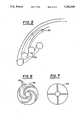
- FIG. 4illustrates areas traced by a row of energy beams output from optical fibers of the first embodiment
- FIG. 5illustrates areas traced by a row of energy beams output from optical fibers of the first embodiment
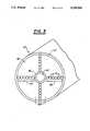
- FIG. 6 and 7show front elevational views of templates used in constructing the first and the second embodiments of the present invention.
- the first embodiment of the present inventionshown in FIG. 2, includes outer wall 12, optical fibers 14, and inner wall 16.
- Inner wall 16 and outer wall 12define outer lumen 18, and inner wall 16 encloses inner lumen 20.
- a guidewiremay be inserted through inner lumen 20.
- optical fibers 14are arranged in groups 22. Within each group 22, the ends of individual optical fibers 14 are positioned in a spiral pattern and the ends are fixed with epoxy 23. Even though FIG. 2 shows only four groups 22, catheter 10 may house more or less groups within outer lumen 18.
- optical fibers 14are as shown only at the distal end of catheter 10.
- the orientation of optical fibers 14 through the remainder of catheter 10may be random, and they do not need to be affixed in a restricting position.
- each of optical fibers 14may be approximately 100 microns, and the outer diameter of catheter 10 may be approximately 2 mm.
- the diameter of inner lumen 20may be about 0.5-0.6 mm.
- the present inventionmay be used to ablate obstructions within a blood vessel as follows. First, the proximal end of fiberoptic catheter 10 is connected to an energy source and the distal end of catheter 10 is placed in a correct location using a guide wire in a conventional manner. Next, the distal end of a fiber optic catheter 10 is rotated gradually as optical fibers 14 emit energy at a target. Thus, a target object may be ablated in a manner safe to the patient. The catheter is rotated until an entire area equivalent to the cross-sectional area of the catheter is ablated. Obviously, as the number of groups of fibers 22 increases, the necessary angle of rotation decreases. With four equiangularly positioned groups 22 as in FIG. 2, the necessary angle of rotation is 90°. As the number of groups of fibers 22 increases, the advantages of the present invention diminish.
- FIG. 3shows a second embodiment of the present invention, again near its distal end.
- the parts corresponding to those of the first embodimenthave been labelled with the same reference numerals, but with each numeral primed.
- the primary difference between the first embodiment and the second embodimentis in the arrangement of group 22, 22' of optical fibers 14, 14'.
- the distal ends of the fibers in each group 22are fixed in a spiral pattern.
- the distal ends of the fibers in each group 22'extend radially straight from inner lumen 20' to outer wall 12'.
- the size and operation of the second embodimentare similar to that of the first embodiment, and such description is not repeated. It may be noted that in the second embodiment, as catheter 10' rotates, area 24 (FIG. 4) traced by outermost beam 26 (from one of fibers 14') does not overlap with area 28 traced by beam 30. Thus, there are regions 32, between areas swept by adjacent beams, that are exposed to less intense radiation. In the first embodiment, the spiral pattern within groups 22 allows for overlaps 34 between areas swept by adjacent beams 36 (FIG. 5), thus ensuring that the entire target area will be exposed to beams 36 in a relatively uniform manner.
- the first embodimentmay be constructed as follows.
- a template 38(FIG. 6) with holes 42 may be placed at the distal end of catheter 10. Holes 42 form spiral patterns, and optical fibers 14 are passed through (not shown) holes 42 of template 38.
- template 38is positioned concentric with catheter 10 and while epoxy is applied to outer lumen 18 at the distal end to fix the fiber ends. Later when epoxy 23 solidifies, template 38 may be removed or cut away and the end of catheter 10 polished. Alternatively, template 38 may be positioned within catheter 10 while the epoxy is poured and then dried, so that template 38 remains in catheter 10.
- fiber optic catheters of the present inventioncontain few optical fibers. This permits inexpensive construction of large fiber optic catheters. Furthermore, required power for the driving optical energy source is also less, because fewer optical fibers 14 need to be energized. In the present invention, the danger of inducing coronary trauma is reduced because the present invention does not supply as much power to the target areas. Also, the present invention retains flexibility, because few optical fibers 14 are packed within catheter 10.
Landscapes
- Physics & Mathematics (AREA)
- Optics & Photonics (AREA)
- General Physics & Mathematics (AREA)
- Health & Medical Sciences (AREA)
- Surgery (AREA)
- Life Sciences & Earth Sciences (AREA)
- Engineering & Computer Science (AREA)
- Medical Informatics (AREA)
- Nuclear Medicine, Radiotherapy & Molecular Imaging (AREA)
- Electromagnetism (AREA)
- Astronomy & Astrophysics (AREA)
- Biomedical Technology (AREA)
- Heart & Thoracic Surgery (AREA)
- Otolaryngology (AREA)
- Molecular Biology (AREA)
- Animal Behavior & Ethology (AREA)
- General Health & Medical Sciences (AREA)
- Public Health (AREA)
- Veterinary Medicine (AREA)
- Laser Surgery Devices (AREA)
- Radiation-Therapy Devices (AREA)
Abstract
Description
Claims (13)
Priority Applications (3)
| Application Number | Priority Date | Filing Date | Title |
|---|---|---|---|
| US07/713,457US5250045A (en) | 1991-06-11 | 1991-06-11 | Optical fiber catheter with spaced optical fiber |
| AU23832/92AAU2383292A (en) | 1991-06-11 | 1992-07-24 | A laser catheter with spaced optical fibers |
| PCT/US1992/006067WO1994002076A1 (en) | 1991-06-11 | 1992-07-24 | A laser catheter with spaced optical fibers |
Applications Claiming Priority (1)
| Application Number | Priority Date | Filing Date | Title |
|---|---|---|---|
| US07/713,457US5250045A (en) | 1991-06-11 | 1991-06-11 | Optical fiber catheter with spaced optical fiber |
Publications (1)
| Publication Number | Publication Date |
|---|---|
| US5250045Atrue US5250045A (en) | 1993-10-05 |
Family
ID=24866220
Family Applications (1)
| Application Number | Title | Priority Date | Filing Date |
|---|---|---|---|
| US07/713,457Expired - LifetimeUS5250045A (en) | 1991-06-11 | 1991-06-11 | Optical fiber catheter with spaced optical fiber |
Country Status (3)
| Country | Link |
|---|---|
| US (1) | US5250045A (en) |
| AU (1) | AU2383292A (en) |
| WO (1) | WO1994002076A1 (en) |
Cited By (51)
| Publication number | Priority date | Publication date | Assignee | Title |
|---|---|---|---|---|
| US5400428A (en)* | 1992-05-13 | 1995-03-21 | Spectranetics Corporation | Method and apparatus for linearly scanning energy over an optical fiber array and coupler for coupling energy to the optical fiber array |
| DE19521298A1 (en)* | 1994-06-16 | 1995-12-21 | Pillco Lp | Catheter for transmitting laser energy in body cavities and method of operating the catheter |
| US6179824B1 (en)* | 1993-05-10 | 2001-01-30 | Arthrocare Corporation | System and methods for electrosurgical restenosis of body lumens |
| US6368318B1 (en) | 1998-01-23 | 2002-04-09 | The Regents Of The University Of California | Opto-acoustic recanilization delivery system |
| US6582423B1 (en) | 1997-06-13 | 2003-06-24 | Arthrocare Corporation | Electrosurgical systems and methods for recanalization of occluded body lumens |
| US6855143B2 (en) | 1997-06-13 | 2005-02-15 | Arthrocare Corporation | Electrosurgical systems and methods for recanalization of occluded body lumens |
| US6879761B2 (en) | 2001-07-03 | 2005-04-12 | Alcatel | Multi axis ribbon |
| US6915806B2 (en) | 1993-05-10 | 2005-07-12 | Arthrocare Corporation | Method for harvesting graft vessel |
| US20060178674A1 (en)* | 2005-02-08 | 2006-08-10 | Mcintyre John | Surgical apparatus having configurable portions |
| US20080077225A1 (en)* | 2006-09-22 | 2008-03-27 | Carlin Donald B | Accuracy lumen sizing and stent expansion |
| US20080154345A1 (en)* | 2006-12-26 | 2008-06-26 | Spectranetics | Multi-Port Light Delivery Catheter And Methods For The Use Thereof |
| US20080249515A1 (en)* | 2006-01-27 | 2008-10-09 | The Spectranetics Corporation | Interventional Devices and Methods For Laser Ablation |
| US20090036744A1 (en)* | 2005-04-04 | 2009-02-05 | Invuity, Inc. | Illuminated Telescoping Cannula |
| US20090182202A1 (en)* | 2005-04-04 | 2009-07-16 | Invuity, Inc. | Optical Waveguide Sheath |
| US20090198221A1 (en)* | 2004-09-17 | 2009-08-06 | The Spectranetics Corporation | Apparatus and methods for directional delivery of laser energy |
| US20090254074A1 (en)* | 2008-04-02 | 2009-10-08 | Spectranetics | Liquid light-guide catheter with optically diverging tip |
| US20100016842A1 (en)* | 2008-07-21 | 2010-01-21 | Spectranetics | Tapered Liquid Light Guide |
| US20100152720A1 (en)* | 2008-12-12 | 2010-06-17 | Spectranetics | Offset catheter |
| US20100152717A1 (en)* | 2008-12-17 | 2010-06-17 | Spectranetics | Eccentric balloon laser catheter |
| US20110009750A1 (en)* | 2004-09-17 | 2011-01-13 | Spectranetics | Cardiovascular imaging system |
| US20120289950A1 (en)* | 2010-01-20 | 2012-11-15 | Wolfgang Neuberger | Device and method for vessel treatment |
| WO2012143883A3 (en)* | 2011-04-20 | 2013-01-03 | Koninklijke Philips Electronics N.V. | Optical fibre being visible in medical imaging applications |
| WO2013052531A1 (en)* | 2011-10-03 | 2013-04-11 | Biolase, Inc. | Surgical laser cutting device |
| US8628519B2 (en) | 2004-09-17 | 2014-01-14 | The Spectranetics Corporation | Rapid exchange bias laser catheter design |
| US20140081252A1 (en)* | 2012-09-14 | 2014-03-20 | The Spectranetics Corporation | Tissue slitting methods and systems |
| US20150133904A1 (en)* | 2012-06-29 | 2015-05-14 | Medtronic Ardian Luxembourg S.A.R.L. | Devices and Methods for Photodynamically Modulating Neural Function in a Human |
| US9289173B2 (en) | 2007-11-09 | 2016-03-22 | The Spectranetics Corporation | Intra-vascular device with pressure detection capabilities using pressure sensitive material |
| US20160120605A1 (en)* | 2013-03-13 | 2016-05-05 | The Spectranetics Corporation | Device and method of ablative cutting with helical tip |
| WO2016081594A1 (en)* | 2014-11-19 | 2016-05-26 | The General Hospital Corporation | System and method for photo-dynamic procedure |
| USD775728S1 (en) | 2015-07-02 | 2017-01-03 | The Spectranetics Corporation | Medical device handle |
| US9623211B2 (en) | 2013-03-13 | 2017-04-18 | The Spectranetics Corporation | Catheter movement control |
| US9757200B2 (en) | 2013-03-14 | 2017-09-12 | The Spectranetics Corporation | Intelligent catheter |
| US9848952B2 (en) | 2007-10-24 | 2017-12-26 | The Spectranetics Corporation | Liquid light guide catheter having biocompatible liquid light guide medium |
| US9907614B2 (en) | 2014-10-29 | 2018-03-06 | The Spectranetics Corporation | Laser energy delivery devices including laser transmission detection systems and methods |
| US10383691B2 (en) | 2013-03-13 | 2019-08-20 | The Spectranetics Corporation | Last catheter with helical internal lumen |
| US10405924B2 (en) | 2014-05-30 | 2019-09-10 | The Spectranetics Corporation | System and method of ablative cutting and vacuum aspiration through primary orifice and auxiliary side port |
| US10492863B2 (en) | 2014-10-29 | 2019-12-03 | The Spectranetics Corporation | Laser energy delivery devices including laser transmission detection systems and methods |
| US10646275B2 (en) | 2014-12-30 | 2020-05-12 | Regents Of The University Of Minnesota | Laser catheter with use of determined material type in vascular system in ablation of material |
| US10646274B2 (en) | 2014-12-30 | 2020-05-12 | Regents Of The University Of Minnesota | Laser catheter with use of reflected light and force indication to determine material type in vascular system |
| US10646118B2 (en) | 2014-12-30 | 2020-05-12 | Regents Of The University Of Minnesota | Laser catheter with use of reflected light to determine material type in vascular system |
| US10758308B2 (en) | 2013-03-14 | 2020-09-01 | The Spectranetics Corporation | Controller to select optical channel parameters in a catheter |
| US10772683B2 (en) | 2014-05-18 | 2020-09-15 | Eximo Medical Ltd. | System for tissue ablation using pulsed laser |
| US10799293B2 (en)* | 2013-03-13 | 2020-10-13 | The Spectranetics Corporation | Laser ablation catheter |
| US10835279B2 (en) | 2013-03-14 | 2020-11-17 | Spectranetics Llc | Distal end supported tissue slitting apparatus |
| US10987167B2 (en) | 2008-11-05 | 2021-04-27 | The Spectranetics Corporation | Biasing laser catheter: monorail design |
| US10987168B2 (en) | 2014-05-29 | 2021-04-27 | Spectranetics Llc | System and method for coordinated laser delivery and imaging |
| US11576724B2 (en) | 2011-02-24 | 2023-02-14 | Eximo Medical Ltd. | Hybrid catheter for vascular intervention |
| US11642169B2 (en) | 2013-03-14 | 2023-05-09 | The Spectranetics Corporation | Smart multiplexed medical laser system |
| US11684420B2 (en) | 2016-05-05 | 2023-06-27 | Eximo Medical Ltd. | Apparatus and methods for resecting and/or ablating an undesired tissue |
| US12038322B2 (en) | 2022-06-21 | 2024-07-16 | Eximo Medical Ltd. | Devices and methods for testing ablation systems |
| US12376904B1 (en) | 2020-09-08 | 2025-08-05 | Angiodynamics, Inc. | Dynamic laser stabilization and calibration system |
Families Citing this family (4)
| Publication number | Priority date | Publication date | Assignee | Title |
|---|---|---|---|---|
| US5651785A (en)* | 1993-09-20 | 1997-07-29 | Abela Laser Systems, Inc. | Optical fiber catheter and method |
| US5782824A (en)* | 1993-09-20 | 1998-07-21 | Abela Laser Systems, Inc. | Cardiac catheter anchoring |
| US5651786A (en)* | 1993-09-20 | 1997-07-29 | Abela Laser Systems, Inc. | Mapping catheter and method |
| US5464404A (en)* | 1993-09-20 | 1995-11-07 | Abela Laser Systems, Inc. | Cardiac ablation catheters and method |
Citations (22)
| Publication number | Priority date | Publication date | Assignee | Title |
|---|---|---|---|---|
| US3279902A (en)* | 1963-07-11 | 1966-10-18 | William L Gardner | Fluid tight sealing of glass fiber devices |
| US3653739A (en)* | 1970-07-02 | 1972-04-04 | American Optical Corp | Leachable bundle of optical fibers |
| US4207874A (en)* | 1978-03-27 | 1980-06-17 | Choy Daniel S J | Laser tunnelling device |
| US4252408A (en)* | 1979-03-09 | 1981-02-24 | The Regents Of The University Of California | Directionally solidified eutectic structure and method of forming the same |
| US4547040A (en)* | 1983-06-21 | 1985-10-15 | Mitsubishi Rayon Co., Ltd. | Optical fiber assembly and process for preparing same |
| US4587972A (en)* | 1984-07-16 | 1986-05-13 | Morantte Jr Bernardo D | Device for diagnostic and therapeutic intravascular intervention |
| US4615583A (en)* | 1983-02-22 | 1986-10-07 | Sumitomo Electric Industries, Ltd. | Image fibers |
| US4622972A (en)* | 1981-10-05 | 1986-11-18 | Varian Associates, Inc. | Ultrasound hyperthermia applicator with variable coherence by multi-spiral focusing |
| US4740047A (en)* | 1985-03-26 | 1988-04-26 | Hatachi Cable, Ltd. | Fiber for lateral beaming of laser beam |
| US4768858A (en)* | 1985-07-08 | 1988-09-06 | Trimedyne, Inc. | Hollow fiberoptic |
| US4790310A (en)* | 1987-02-04 | 1988-12-13 | Robert Ginsburg | Laser catheter having wide angle sweep |
| US4819632A (en)* | 1986-05-19 | 1989-04-11 | Davies David H | Retrolasing catheter and method |
| US4832023A (en)* | 1987-06-03 | 1989-05-23 | Mcm Laboratories, Inc. | Method and apparatus for reducing blockage in body channels |
| US4834093A (en)* | 1986-02-03 | 1989-05-30 | Littleford Phillip O | Dilation catheter and method |
| US4844062A (en)* | 1987-10-23 | 1989-07-04 | Spectranetics Corporation | Rotating fiberoptic laser catheter assembly with eccentric lumen |
| US4848336A (en)* | 1981-12-11 | 1989-07-18 | Fox Kenneth R | Apparatus for laser treatment of body lumens |
| US4905689A (en)* | 1987-06-25 | 1990-03-06 | Stack Richard S | Method of using a laser catheter |
| US4913142A (en)* | 1985-03-22 | 1990-04-03 | Massachusetts Institute Of Technology | Catheter for laser angiosurgery |
| US4917084A (en)* | 1985-07-31 | 1990-04-17 | C. R. Bard, Inc. | Infrared laser catheter system |
| US4934340A (en)* | 1989-06-08 | 1990-06-19 | Hemo Laser Corporation | Device for guiding medical catheters and scopes |
| US4963142A (en)* | 1988-10-28 | 1990-10-16 | Hanspeter Loertscher | Apparatus for endolaser microsurgery |
| US4984859A (en)* | 1987-06-19 | 1991-01-15 | Mitsubishi Rayon Co., Ltd. | Optical fiber ribbon end-structure |
- 1991
- 1991-06-11USUS07/713,457patent/US5250045A/ennot_activeExpired - Lifetime
- 1992
- 1992-07-24AUAU23832/92Apatent/AU2383292A/ennot_activeAbandoned
- 1992-07-24WOPCT/US1992/006067patent/WO1994002076A1/enactiveApplication Filing
Patent Citations (22)
| Publication number | Priority date | Publication date | Assignee | Title |
|---|---|---|---|---|
| US3279902A (en)* | 1963-07-11 | 1966-10-18 | William L Gardner | Fluid tight sealing of glass fiber devices |
| US3653739A (en)* | 1970-07-02 | 1972-04-04 | American Optical Corp | Leachable bundle of optical fibers |
| US4207874A (en)* | 1978-03-27 | 1980-06-17 | Choy Daniel S J | Laser tunnelling device |
| US4252408A (en)* | 1979-03-09 | 1981-02-24 | The Regents Of The University Of California | Directionally solidified eutectic structure and method of forming the same |
| US4622972A (en)* | 1981-10-05 | 1986-11-18 | Varian Associates, Inc. | Ultrasound hyperthermia applicator with variable coherence by multi-spiral focusing |
| US4848336A (en)* | 1981-12-11 | 1989-07-18 | Fox Kenneth R | Apparatus for laser treatment of body lumens |
| US4615583A (en)* | 1983-02-22 | 1986-10-07 | Sumitomo Electric Industries, Ltd. | Image fibers |
| US4547040A (en)* | 1983-06-21 | 1985-10-15 | Mitsubishi Rayon Co., Ltd. | Optical fiber assembly and process for preparing same |
| US4587972A (en)* | 1984-07-16 | 1986-05-13 | Morantte Jr Bernardo D | Device for diagnostic and therapeutic intravascular intervention |
| US4913142A (en)* | 1985-03-22 | 1990-04-03 | Massachusetts Institute Of Technology | Catheter for laser angiosurgery |
| US4740047A (en)* | 1985-03-26 | 1988-04-26 | Hatachi Cable, Ltd. | Fiber for lateral beaming of laser beam |
| US4768858A (en)* | 1985-07-08 | 1988-09-06 | Trimedyne, Inc. | Hollow fiberoptic |
| US4917084A (en)* | 1985-07-31 | 1990-04-17 | C. R. Bard, Inc. | Infrared laser catheter system |
| US4834093A (en)* | 1986-02-03 | 1989-05-30 | Littleford Phillip O | Dilation catheter and method |
| US4819632A (en)* | 1986-05-19 | 1989-04-11 | Davies David H | Retrolasing catheter and method |
| US4790310A (en)* | 1987-02-04 | 1988-12-13 | Robert Ginsburg | Laser catheter having wide angle sweep |
| US4832023A (en)* | 1987-06-03 | 1989-05-23 | Mcm Laboratories, Inc. | Method and apparatus for reducing blockage in body channels |
| US4984859A (en)* | 1987-06-19 | 1991-01-15 | Mitsubishi Rayon Co., Ltd. | Optical fiber ribbon end-structure |
| US4905689A (en)* | 1987-06-25 | 1990-03-06 | Stack Richard S | Method of using a laser catheter |
| US4844062A (en)* | 1987-10-23 | 1989-07-04 | Spectranetics Corporation | Rotating fiberoptic laser catheter assembly with eccentric lumen |
| US4963142A (en)* | 1988-10-28 | 1990-10-16 | Hanspeter Loertscher | Apparatus for endolaser microsurgery |
| US4934340A (en)* | 1989-06-08 | 1990-06-19 | Hemo Laser Corporation | Device for guiding medical catheters and scopes |
Cited By (104)
| Publication number | Priority date | Publication date | Assignee | Title |
|---|---|---|---|---|
| US5400428A (en)* | 1992-05-13 | 1995-03-21 | Spectranetics Corporation | Method and apparatus for linearly scanning energy over an optical fiber array and coupler for coupling energy to the optical fiber array |
| US6179824B1 (en)* | 1993-05-10 | 2001-01-30 | Arthrocare Corporation | System and methods for electrosurgical restenosis of body lumens |
| US6915806B2 (en) | 1993-05-10 | 2005-07-12 | Arthrocare Corporation | Method for harvesting graft vessel |
| US7505812B1 (en) | 1993-05-10 | 2009-03-17 | Arthrocare Corporation | Electrosurgical system for treating restenosis of body lumens |
| DE19521298A1 (en)* | 1994-06-16 | 1995-12-21 | Pillco Lp | Catheter for transmitting laser energy in body cavities and method of operating the catheter |
| US6582423B1 (en) | 1997-06-13 | 2003-06-24 | Arthrocare Corporation | Electrosurgical systems and methods for recanalization of occluded body lumens |
| US6855143B2 (en) | 1997-06-13 | 2005-02-15 | Arthrocare Corporation | Electrosurgical systems and methods for recanalization of occluded body lumens |
| US6368318B1 (en) | 1998-01-23 | 2002-04-09 | The Regents Of The University Of California | Opto-acoustic recanilization delivery system |
| US6879761B2 (en) | 2001-07-03 | 2005-04-12 | Alcatel | Multi axis ribbon |
| US8628519B2 (en) | 2004-09-17 | 2014-01-14 | The Spectranetics Corporation | Rapid exchange bias laser catheter design |
| US10959699B2 (en) | 2004-09-17 | 2021-03-30 | The Spectranetics Corporation | Cardiovascular imaging system |
| US9308047B2 (en) | 2004-09-17 | 2016-04-12 | The Spectranetics Corporation | Rapid exchange bias laser catheter design |
| US7846153B2 (en) | 2004-09-17 | 2010-12-07 | The Spectranetics Corporation | Apparatus and methods for directional delivery of laser energy |
| US8545488B2 (en) | 2004-09-17 | 2013-10-01 | The Spectranetics Corporation | Cardiovascular imaging system |
| US20090198221A1 (en)* | 2004-09-17 | 2009-08-06 | The Spectranetics Corporation | Apparatus and methods for directional delivery of laser energy |
| US20110009750A1 (en)* | 2004-09-17 | 2011-01-13 | Spectranetics | Cardiovascular imaging system |
| US10111709B2 (en) | 2004-09-17 | 2018-10-30 | The Spectranetics Corporation | Rapid exchange bias laser catheter design |
| US20060178674A1 (en)* | 2005-02-08 | 2006-08-10 | Mcintyre John | Surgical apparatus having configurable portions |
| US10675115B2 (en) | 2005-04-04 | 2020-06-09 | Invuity, Inc. | Illuminated telescoping cannula |
| US20090036744A1 (en)* | 2005-04-04 | 2009-02-05 | Invuity, Inc. | Illuminated Telescoping Cannula |
| US10531933B2 (en) | 2005-04-04 | 2020-01-14 | Invuity, Inc. | Illuminated telescoping cannula |
| US10512518B2 (en) | 2005-04-04 | 2019-12-24 | Invuity, Inc. | Illuminated telescoping cannula |
| US20110201889A1 (en)* | 2005-04-04 | 2011-08-18 | Invuity, Inc. | Illuminated cannula |
| US9504373B2 (en) | 2005-04-04 | 2016-11-29 | Invuity, Inc. | Illuminated cannula |
| US8162824B2 (en)* | 2005-04-04 | 2012-04-24 | Invuity, Inc. | Optical waveguide sheath |
| US10568712B2 (en) | 2005-04-04 | 2020-02-25 | Invuity, Inc. | Illuminated telescoping cannula |
| US9072455B2 (en) | 2005-04-04 | 2015-07-07 | Invuity, Inc. | Optical waveguide sheath |
| US9005115B2 (en) | 2005-04-04 | 2015-04-14 | Invuity, Inc. | Illuminated telescoping cannula |
| US20090182202A1 (en)* | 2005-04-04 | 2009-07-16 | Invuity, Inc. | Optical Waveguide Sheath |
| US10548682B2 (en) | 2005-04-04 | 2020-02-04 | Invuity, Inc. | Illuminated telescoping cannula |
| US10729511B2 (en) | 2005-04-04 | 2020-08-04 | Invuity, Inc. | Illuminated telescoping cannula |
| US8708896B2 (en) | 2005-04-04 | 2014-04-29 | Invuity, Inc. | Illuminated cannula |
| US20080249515A1 (en)* | 2006-01-27 | 2008-10-09 | The Spectranetics Corporation | Interventional Devices and Methods For Laser Ablation |
| US20080077225A1 (en)* | 2006-09-22 | 2008-03-27 | Carlin Donald B | Accuracy lumen sizing and stent expansion |
| US20080154345A1 (en)* | 2006-12-26 | 2008-06-26 | Spectranetics | Multi-Port Light Delivery Catheter And Methods For The Use Thereof |
| US8104483B2 (en) | 2006-12-26 | 2012-01-31 | The Spectranetics Corporation | Multi-port light delivery catheter and methods for the use thereof |
| US9848952B2 (en) | 2007-10-24 | 2017-12-26 | The Spectranetics Corporation | Liquid light guide catheter having biocompatible liquid light guide medium |
| US10631931B2 (en) | 2007-10-24 | 2020-04-28 | The Spectranetics Corporation | Liquid light guide catheter having biocompatible liquid light guide medium |
| US11166647B2 (en) | 2007-11-09 | 2021-11-09 | The Spectranetics Corporation | Intra-vascular device with pressure detection capabilities using pressure sensitive material |
| US9289173B2 (en) | 2007-11-09 | 2016-03-22 | The Spectranetics Corporation | Intra-vascular device with pressure detection capabilities using pressure sensitive material |
| US20090254074A1 (en)* | 2008-04-02 | 2009-10-08 | Spectranetics | Liquid light-guide catheter with optically diverging tip |
| US9421065B2 (en) | 2008-04-02 | 2016-08-23 | The Spectranetics Corporation | Liquid light-guide catheter with optically diverging tip |
| US9855100B2 (en) | 2008-04-02 | 2018-01-02 | The Spectranetics Corporation | Liquid light-guide catheter with optically diverging tip |
| US10716625B2 (en) | 2008-04-02 | 2020-07-21 | The Spectranetics Corporation | Liquid light-guide catheter with optically diverging tip |
| US9339337B2 (en) | 2008-07-21 | 2016-05-17 | The Spectranetics Corporation | Tapered liquid light guide |
| US20100016842A1 (en)* | 2008-07-21 | 2010-01-21 | Spectranetics | Tapered Liquid Light Guide |
| US10092357B2 (en) | 2008-07-21 | 2018-10-09 | The Spectranetics Corporation | Tapered liquid light guide |
| US8979828B2 (en) | 2008-07-21 | 2015-03-17 | The Spectranetics Corporation | Tapered liquid light guide |
| US10987167B2 (en) | 2008-11-05 | 2021-04-27 | The Spectranetics Corporation | Biasing laser catheter: monorail design |
| US9408665B2 (en) | 2008-12-12 | 2016-08-09 | The Spectranetics Corporation | Offset catheter |
| US20100152720A1 (en)* | 2008-12-12 | 2010-06-17 | Spectranetics | Offset catheter |
| US8702773B2 (en) | 2008-12-17 | 2014-04-22 | The Spectranetics Corporation | Eccentric balloon laser catheter |
| US9649159B2 (en) | 2008-12-17 | 2017-05-16 | The Spectranetics Corporation | Eccentric balloon laser catheter |
| US9907615B2 (en) | 2008-12-17 | 2018-03-06 | The Spectranetics Corporation | Eccentric balloon laser catheter |
| US20100152717A1 (en)* | 2008-12-17 | 2010-06-17 | Spectranetics | Eccentric balloon laser catheter |
| US20120289950A1 (en)* | 2010-01-20 | 2012-11-15 | Wolfgang Neuberger | Device and method for vessel treatment |
| US11129676B2 (en)* | 2010-01-20 | 2021-09-28 | Biolitec Unternehmensbeteiligungs Ii Ag | Device and method for vessel treatment |
| US12042223B2 (en) | 2011-02-24 | 2024-07-23 | Eximo Medical Ltd. | Hybrid catheter for vascular intervention |
| US11576724B2 (en) | 2011-02-24 | 2023-02-14 | Eximo Medical Ltd. | Hybrid catheter for vascular intervention |
| WO2012143883A3 (en)* | 2011-04-20 | 2013-01-03 | Koninklijke Philips Electronics N.V. | Optical fibre being visible in medical imaging applications |
| WO2013052531A1 (en)* | 2011-10-03 | 2013-04-11 | Biolase, Inc. | Surgical laser cutting device |
| US9956039B2 (en) | 2011-10-03 | 2018-05-01 | Biolase, Inc. | Surgical laser cutting device |
| US10321957B2 (en) | 2011-10-03 | 2019-06-18 | Biolase, Inc. | Surgical laser cutting device |
| US20150133904A1 (en)* | 2012-06-29 | 2015-05-14 | Medtronic Ardian Luxembourg S.A.R.L. | Devices and Methods for Photodynamically Modulating Neural Function in a Human |
| US9763692B2 (en) | 2012-09-14 | 2017-09-19 | The Spectranetics Corporation | Tissue slitting methods and systems |
| US10531891B2 (en)* | 2012-09-14 | 2020-01-14 | The Spectranetics Corporation | Tissue slitting methods and systems |
| US10368900B2 (en) | 2012-09-14 | 2019-08-06 | The Spectranetics Corporation | Tissue slitting methods and systems |
| US9413896B2 (en) | 2012-09-14 | 2016-08-09 | The Spectranetics Corporation | Tissue slitting methods and systems |
| US9949753B2 (en) | 2012-09-14 | 2018-04-24 | The Spectranetics Corporation | Tissue slitting methods and systems |
| US20140081252A1 (en)* | 2012-09-14 | 2014-03-20 | The Spectranetics Corporation | Tissue slitting methods and systems |
| US9724122B2 (en) | 2012-09-14 | 2017-08-08 | The Spectranetics Corporation | Expandable lead jacket |
| US11596435B2 (en) | 2012-09-14 | 2023-03-07 | Specrtranetics Llc | Tissue slitting methods and systems |
| US20160120605A1 (en)* | 2013-03-13 | 2016-05-05 | The Spectranetics Corporation | Device and method of ablative cutting with helical tip |
| US10206745B2 (en) | 2013-03-13 | 2019-02-19 | The Spectranetics Corporation | Catheter movement control |
| US10485613B2 (en) | 2013-03-13 | 2019-11-26 | The Spectranetics Corporation | Device and method of ablative cutting with helical tip |
| US9937005B2 (en)* | 2013-03-13 | 2018-04-10 | The Spectranetics Corporation | Device and method of ablative cutting with helical tip |
| US12167894B2 (en) | 2013-03-13 | 2024-12-17 | The Spectranetics Corporation | Catheter movement control |
| US9623211B2 (en) | 2013-03-13 | 2017-04-18 | The Spectranetics Corporation | Catheter movement control |
| US10799293B2 (en)* | 2013-03-13 | 2020-10-13 | The Spectranetics Corporation | Laser ablation catheter |
| US10383691B2 (en) | 2013-03-13 | 2019-08-20 | The Spectranetics Corporation | Last catheter with helical internal lumen |
| US9827055B2 (en) | 2013-03-13 | 2017-11-28 | The Spectranetics Corporation | Catheter movement control |
| US10758308B2 (en) | 2013-03-14 | 2020-09-01 | The Spectranetics Corporation | Controller to select optical channel parameters in a catheter |
| US10835279B2 (en) | 2013-03-14 | 2020-11-17 | Spectranetics Llc | Distal end supported tissue slitting apparatus |
| US11925380B2 (en) | 2013-03-14 | 2024-03-12 | Spectranetics Llc | Distal end supported tissue slitting apparatus |
| US11642169B2 (en) | 2013-03-14 | 2023-05-09 | The Spectranetics Corporation | Smart multiplexed medical laser system |
| US10092363B2 (en) | 2013-03-14 | 2018-10-09 | The Spectranetics Corporation | Intelligent catheter |
| US9757200B2 (en) | 2013-03-14 | 2017-09-12 | The Spectranetics Corporation | Intelligent catheter |
| US11116573B2 (en) | 2014-05-18 | 2021-09-14 | Eximo Medical Ltd | System for tissue ablation using pulsed laser |
| US10792103B2 (en) | 2014-05-18 | 2020-10-06 | Eximo Medical Ltd. | System for tissue ablation using pulsed laser |
| US10772683B2 (en) | 2014-05-18 | 2020-09-15 | Eximo Medical Ltd. | System for tissue ablation using pulsed laser |
| US10987168B2 (en) | 2014-05-29 | 2021-04-27 | Spectranetics Llc | System and method for coordinated laser delivery and imaging |
| US10405924B2 (en) | 2014-05-30 | 2019-09-10 | The Spectranetics Corporation | System and method of ablative cutting and vacuum aspiration through primary orifice and auxiliary side port |
| US10517673B2 (en) | 2014-10-29 | 2019-12-31 | The Spectranetics Corporation | Laser energy delivery devices including laser transmission detection systems and methods |
| US9907614B2 (en) | 2014-10-29 | 2018-03-06 | The Spectranetics Corporation | Laser energy delivery devices including laser transmission detection systems and methods |
| US10492863B2 (en) | 2014-10-29 | 2019-12-03 | The Spectranetics Corporation | Laser energy delivery devices including laser transmission detection systems and methods |
| WO2016081594A1 (en)* | 2014-11-19 | 2016-05-26 | The General Hospital Corporation | System and method for photo-dynamic procedure |
| US10780294B2 (en) | 2014-11-19 | 2020-09-22 | The General Hospital Corporation | System and method for photo-dynamic procedure |
| US10646274B2 (en) | 2014-12-30 | 2020-05-12 | Regents Of The University Of Minnesota | Laser catheter with use of reflected light and force indication to determine material type in vascular system |
| US10646118B2 (en) | 2014-12-30 | 2020-05-12 | Regents Of The University Of Minnesota | Laser catheter with use of reflected light to determine material type in vascular system |
| US10646275B2 (en) | 2014-12-30 | 2020-05-12 | Regents Of The University Of Minnesota | Laser catheter with use of determined material type in vascular system in ablation of material |
| USD775728S1 (en) | 2015-07-02 | 2017-01-03 | The Spectranetics Corporation | Medical device handle |
| US11684420B2 (en) | 2016-05-05 | 2023-06-27 | Eximo Medical Ltd. | Apparatus and methods for resecting and/or ablating an undesired tissue |
| US12376904B1 (en) | 2020-09-08 | 2025-08-05 | Angiodynamics, Inc. | Dynamic laser stabilization and calibration system |
| US12038322B2 (en) | 2022-06-21 | 2024-07-16 | Eximo Medical Ltd. | Devices and methods for testing ablation systems |
Also Published As
| Publication number | Publication date |
|---|---|
| WO1994002076A1 (en) | 1994-02-03 |
| AU2383292A (en) | 1994-02-14 |
Similar Documents
| Publication | Publication Date | Title |
|---|---|---|
| US5250045A (en) | Optical fiber catheter with spaced optical fiber | |
| US5217454A (en) | Laser delivery catheter | |
| CA1295374C (en) | Wire guided laser catheter | |
| EP0902653B1 (en) | Balloon catheter for photodynamic therapy | |
| US4850351A (en) | Wire guided laser catheter | |
| US7811281B1 (en) | Excimer laser catheter | |
| US4844062A (en) | Rotating fiberoptic laser catheter assembly with eccentric lumen | |
| EP0566873B1 (en) | Two-piece tip for fiber optic catheter | |
| US5454794A (en) | Steerable light diffusing catheter | |
| EP0542901B1 (en) | Fiber optic laser catheter | |
| US4770653A (en) | Laser angioplasty | |
| US20070049909A1 (en) | Magnetically enabled optical ablation device | |
| US4784132B1 (en) | ||
| US5703985A (en) | Optical fiber device and method for laser surgery procedures | |
| US4819632A (en) | Retrolasing catheter and method | |
| US5167686A (en) | Catheter system for controlled removal by radiant energy of biological obstructions | |
| EP0525184A4 (en) | Delivery system for pulsed excimer laser light | |
| CA2004417A1 (en) | Single axis/angeled beam laser catheter | |
| CA2003069A1 (en) | Angioplasty catheter with off-axis beam delivery fiber | |
| CA1266304A (en) | Catheter system for controlled removal by radiant energy of biological obstructions | |
| CN113180820A (en) | Radial laser ablation catheter | |
| JP2023047482A (en) | Light irradiation medical device |
Legal Events
| Date | Code | Title | Description |
|---|---|---|---|
| AS | Assignment | Owner name:SPECTRANETICS CORPORATION, THE, A CORP. OF CO, CO Free format text:ASSIGNMENT OF ASSIGNORS INTEREST.;ASSIGNOR:BOHLEY, THOMAS K.;REEL/FRAME:005735/0202 Effective date:19910606 | |
| STCF | Information on status: patent grant | Free format text:PATENTED CASE | |
| FPAY | Fee payment | Year of fee payment:4 | |
| AS | Assignment | Owner name:SILICON VALLEY BANK, CALIFORNIA Free format text:SECURITY INTEREST;ASSIGNORS:SPECTRANETICS CORPORATION, THE;POLYMICRO TECHNOLOGIES;REEL/FRAME:009178/0887 Effective date:19971224 Owner name:SILICON VALLEY BANK, CALIFORNIA Free format text:SECURITY INTEREST;ASSIGNORS:THE SPECTRANETICS CORPORATION;POLYMICRO TECHNOLOGIES;REEL/FRAME:009178/0887 Effective date:19971224 | |
| FEPP | Fee payment procedure | Free format text:PAYOR NUMBER ASSIGNED (ORIGINAL EVENT CODE: ASPN); ENTITY STATUS OF PATENT OWNER: SMALL ENTITY | |
| FPAY | Fee payment | Year of fee payment:8 | |
| FPAY | Fee payment | Year of fee payment:12 | |
| AS | Assignment | Owner name:THE SPECTRANETICS CORPORATION POLYMICRO TECHNOLOGI Free format text:RELEASE;ASSIGNOR:SILCON VALLEY BANK;REEL/FRAME:018626/0412 Effective date:20060901 Owner name:SPECTRANETICS CORPORATION POLYMICRO TECHNOLOGIES, Free format text:RELEASE;ASSIGNOR:SILCON VALLEY BANK;REEL/FRAME:018626/0412 Effective date:20060901 | |
| AS | Assignment | Owner name:WELLS FARGO BANK, NATIONAL ASSOCIATION, COLORADO Free format text:SECURITY AGREEMENT;ASSIGNOR:THE SPECTRANETICS CORPORATION;REEL/FRAME:026100/0647 Effective date:20110225 | |
| AS | Assignment | Owner name:THE SPECTRANETICS CORPORATION, COLORADO Free format text:CORRECTIVE ASSIGNMENT TO CORRECT THE LISTING OF ASSIGNEE NAMES PREVIOUSLY RECORDED ON REEL 018626 FRAME 0412. ASSIGNOR(S) HEREBY CONFIRMS THE CONVEYING PARTY SILICON VALLEY BANK TO THE SPECTRANETICS CORPORATION AND POLYMICRO TECHNOLOGIES, INC.;ASSIGNOR:SILICON VALLEY BANK;REEL/FRAME:026359/0782 Effective date:20061117 Owner name:POLYMICRO TECHNOLOGIES, INC., ARIZONA Free format text:CORRECTIVE ASSIGNMENT TO CORRECT THE LISTING OF ASSIGNEE NAMES PREVIOUSLY RECORDED ON REEL 018626 FRAME 0412. ASSIGNOR(S) HEREBY CONFIRMS THE CONVEYING PARTY SILICON VALLEY BANK TO THE SPECTRANETICS CORPORATION AND POLYMICRO TECHNOLOGIES, INC.;ASSIGNOR:SILICON VALLEY BANK;REEL/FRAME:026359/0782 Effective date:20061117 Owner name:THE SPECTRANETICS CORPORATION, COLORADO Free format text:CORRECTIVE ASSIGNMENT TO CORRECT THE ASSIGNEE NAME AND ADDRESS PREVIOUSLY RECORDED ON REEL 005735 FRAME 0202. ASSIGNOR(S) HEREBY CONFIRMS THE THE SPECTRANETICS CORPORATION 96 TALAMINE COURT COLORADO SPRINGS, CO 80907;ASSIGNOR:BOHLEY, THOMAS K.;REEL/FRAME:026360/0361 Effective date:19910606 | |
| AS | Assignment | Owner name:THE SPECTRANETICS CORPORATION, COLORADO Free format text:RELEASE BY SECURED PARTY;ASSIGNOR:WELLS FARGO BANK, NATIONAL ASSOCIATION;REEL/FRAME:037261/0819 Effective date:20151208 |