US5249465A - Accelerometer utilizing an annular mass - Google Patents
Accelerometer utilizing an annular massDownload PDFInfo
- Publication number
- US5249465A US5249465AUS07/626,133US62613390AUS5249465AUS 5249465 AUS5249465 AUS 5249465AUS 62613390 AUS62613390 AUS 62613390AUS 5249465 AUS5249465 AUS 5249465A
- Authority
- US
- United States
- Prior art keywords
- mass
- annular
- accelerometer
- seismic mass
- seismic
- Prior art date
- Legal status (The legal status is an assumption and is not a legal conclusion. Google has not performed a legal analysis and makes no representation as to the accuracy of the status listed.)
- Expired - Lifetime
Links
- 230000033001locomotionEffects0.000claimsabstractdescription12
- 239000000758substrateSubstances0.000claimsdescription21
- NJPPVKZQTLUDBO-UHFFFAOYSA-NnovaluronChemical compoundC1=C(Cl)C(OC(F)(F)C(OC(F)(F)F)F)=CC=C1NC(=O)NC(=O)C1=C(F)C=CC=C1FNJPPVKZQTLUDBO-UHFFFAOYSA-N0.000claimsdescription11
- 230000001133accelerationEffects0.000claimsdescription10
- 230000000694effectsEffects0.000claimsdescription6
- 238000000034methodMethods0.000claimsdescription4
- 230000007935neutral effectEffects0.000claimsdescription4
- 230000035945sensitivityEffects0.000claimsdescription4
- XUIMIQQOPSSXEZ-UHFFFAOYSA-NSiliconChemical compound[Si]XUIMIQQOPSSXEZ-UHFFFAOYSA-N0.000claims8
- 229910052710siliconInorganic materials0.000claims8
- 239000010703siliconSubstances0.000claims8
- 238000006073displacement reactionMethods0.000abstractdescription5
- 239000003990capacitorSubstances0.000description7
- 230000008901benefitEffects0.000description2
- 238000010586diagramMethods0.000description2
- 239000000463materialSubstances0.000description2
- 230000035939shockEffects0.000description2
- 238000013459approachMethods0.000description1
- 230000008878couplingEffects0.000description1
- 238000010168coupling processMethods0.000description1
- 238000005859coupling reactionMethods0.000description1
- 238000013016dampingMethods0.000description1
- 238000001514detection methodMethods0.000description1
- 230000001627detrimental effectEffects0.000description1
- 238000005259measurementMethods0.000description1
- 238000005459micromachiningMethods0.000description1
- 229910021420polycrystalline siliconInorganic materials0.000description1
- 239000004065semiconductorSubstances0.000description1
- 230000001052transient effectEffects0.000description1
Images

Classifications
- G—PHYSICS
- G01—MEASURING; TESTING
- G01P—MEASURING LINEAR OR ANGULAR SPEED, ACCELERATION, DECELERATION, OR SHOCK; INDICATING PRESENCE, ABSENCE, OR DIRECTION, OF MOVEMENT
- G01P15/00—Measuring acceleration; Measuring deceleration; Measuring shock, i.e. sudden change of acceleration
- G01P15/02—Measuring acceleration; Measuring deceleration; Measuring shock, i.e. sudden change of acceleration by making use of inertia forces using solid seismic masses
- G01P15/08—Measuring acceleration; Measuring deceleration; Measuring shock, i.e. sudden change of acceleration by making use of inertia forces using solid seismic masses with conversion into electric or magnetic values
- G01P15/13—Measuring acceleration; Measuring deceleration; Measuring shock, i.e. sudden change of acceleration by making use of inertia forces using solid seismic masses with conversion into electric or magnetic values by measuring the force required to restore a proofmass subjected to inertial forces to a null position
- G01P15/131—Measuring acceleration; Measuring deceleration; Measuring shock, i.e. sudden change of acceleration by making use of inertia forces using solid seismic masses with conversion into electric or magnetic values by measuring the force required to restore a proofmass subjected to inertial forces to a null position with electrostatic counterbalancing means
Definitions
- the present inventionrelates, in general, to micromachined capacitance type accelerometers, and more particularly to annular mass accelerometers using electrostatic forces to position the annular mass.
- Accelerometersare generally based on the principle of a seismic mass suspended in some way by a spring system, with acceleration being measured indirectly by measuring displacement of the seismic mass from a neutral position.
- Sensitivity of the accelerometerthat is to say the displacement for a given acceleration, depends on two quantities: the size of the seismic mass and the strength of the spring.
- the seismic masscan easily be made to remain stable indefinitely but the strength (modulus of elasticity) of the spring may vary, changing the displacement of the seismic mass for a given acceleration and making the accelerometer lose accuracy or in extreme cases making the accelerometer unserviceable.
- Micromachined accelerometershave made it possible to reduce the effect of the spring by using more easily manipulated electrostatic forces instead.
- Previous approacheshave used a single block as a seismic mass; however it is extremely hard to control twisting effects with an electrostatic control system using this geometry for the seismic mass.
- the mechanical spring strengthmust still be a significant factor in operation of the accelerometer with the electrostatic forces being used primarily for a damping effect to reduce excessive motion of the seismic mass.
- the present inventionprovides an accelerometer in which the effects of a spring supporting a seismic mass are minimized by relying on electrostatic forces rather than the mechanical spring action to position the seismic mass. Due to the geometry of the invention, the mechanical spring is required only for electrical coupling to the mass and as a means to hold the mass in position laterally. Twisting of the mass is controlled electrostatically by means of multiple sets of electrodes around the mass.
- FIG. 1depicts a functional block diagram of a typical position detector and electrostatic control system according to the prior art
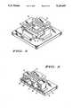
- FIG. 2depicts a top view of an annulus accelerometer as a preferred embodiment of the present invention
- FIG. 3depicts a side view cut through the center of the accelerometer of FIG. 2;
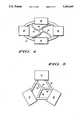
- FIG. 4depicts a top view of an annular accelerometer utilizing an elliptical mass
- FIG. 5shows a top view of an annular accelerometer utilizing a triangular mass.
- FIG. 11is a functional block diagram of a typical position detector and electrostatic control system according to the prior art.
- the systemuses a pulse width modulation scheme both to sense the position of seismic mass 13 and to apply an electrostatic force to keep seismic mass 13 in position.
- Systems typical of the prior artare detailed in S. Suzuki et al, "Semiconductor Capacitance-type Accelerometer with PWM Electrostatic Servo Technique", Sensors and Actuators, A21-A23 (1990), copyright Elsevier Seqoia, pages 316 to 319, and in H.
- a capacitance sensor 18is electrically coupled to electrodes 16 and 17 as well as to seismic mass 13.
- Capacitance sensor 18senses the spacing between electrode 16 and seismic mass 13 relative to the spacing between electrode 17 and seismic mass 13 by sensing the ratio of the value of capacitor 24 to the value of capacitor 26.
- a voltage proportional to the ratio of the two capacitorsis coupled to the input of a pulse width modulated pulse generator 19.
- Pulse generator 19produces a train of pulses at a constant repetition rate with a pulse width that is proportional to the input voltage. This pulse train is then coupled to electrode 16, and also inverted by inverter 21 then coupled to electrode 17.
- the pulse width of the pulsesis proportional to the motion of seismic mass 13 and has a polarity which produces a force opposing the direction of motion, an electrostatic force is applied to seismic mass 13 which will restore seismic mass 13 to its original position. Integrating the pulse train with a low pass filter 22 produces an output voltage at a terminal 23 that is proportional to the acceleration applied to the system.
- FIG. 2depicts a top view of an annulus accelerometer as a preferred embodiment of this invention.
- a seismic mass 28 in the form of an annular rectangleis coupled mechanically and electrically to a central pedestal 27 by a plurality of support arms or springs 29.
- Springs 29are fabricated as a long arm in the shape of a spiral to produce a mechanically weak spring. This arrangement allows vertical motion freely, but provides some support laterally to minimize shock effects.
- seismic mass 27, springs 29 and pedestal 27are manufactured from a single piece of polycrystalline silicon by methods well known in the micromachining arts.
- An electrode pairconsists of a matched pair of electrodes, one electrode placed above seismic mass 28 and one below seismic mass 28 so as to form a pair of capacitors similar to capacitors 24 and 26 (FIG. 1). Electrode pairs are positioned on each side of annular rectangular seismic mass 28. A first top electrode 31 is positioned opposite a second top electrode 32 on a first axis, and a third top electrode 33 is positioned opposite a fourth top electrode 34 on a second axis. The matching lower electrodes of the electrode pairs are not visible in FIG. 2. This symmetrical arrangement of electrode pairs provides an inherently balanced system for acceleration forces, for gravitational forces, and for electrostatic forces.
- FIG. 3depicts a side view cut through the center of an annulus accelerometer as a preferred embodiment of this invention.
- a substrate 36supports central pedestal 27, which in turn is coupled electrically and mechanically to seismic mass 28 by spring 29.
- Top electrode 31is positioned above one side of seismic mass 28 and is paired with a lower electrode 37 positioned below the same side.
- top electrode 32is positioned on the opposing side of seismic mass 28 and is paired with a lower electrode 38. Only two of the four electrode pairs can be seen in the cross-sectional view of FIG. 3. Electrodes 31, 32, 37, and 38 together with pedestal 27 are electrically isolated from substrate 36 and from each other by an oxide layer 39 or the like.
- Electrode pair 31 and 37 together with seismic mass 28are electrically coupled to a position detector and electrostatic control system similar to that shown in FIG. 1.
- An accelerating forceis applied to substrate 36 so as to move substrate 36 in an upward direction perpendicular to substrate 36. Since spring 29 is too weak to exert significant force, seismic mass 28 remains stationary and substrate 36 moves closer to seismic mass 28. This motion causes the capacitance between electrode 37 and seismic mass 28 to increase and the capacitance between electrode 31 and seismic mass 28 to decrease.
- FIG. 4depicts a top view of an annular accelerometer utilizing an elliptical mass 41 as an alternate embodiment in accordance with the present invention.
- Elliptical mass 41is shaped as an elliptical annulus, coupled mechanically and electrically to a central pedestal 44 by a plurality of springs 43.
- a plurality of electrode pairs 42are positioned around the circumference of elliptical mass 41.
- FIG. 5depicts a top view of an annular accelerometer utilizing a triangular mass 46 as an alternative embodiment in accordance with the present invention.
- Triangular mass 46is shaped as a triangular annulus, coupled mechanically and electrically to a central pedestal 49 by a plurality of springs 48.
- a plurality of electrode pairs 47are positioned at the vertices of triangular mass 46.
- Each of the three remaining electrode pairsis also coupled to its own position detector and electrostatic control system which acts to maintain its respective side of seismic mass 28 in a neutral position.
- the four position detector and electrostatic control systemsdetect and correct any motion due to twisting or acceleration by each system maintaining the appropriate side in a fixed position relative to substrate 36.
- the resultis four independent output signals which may be summed to provide a measure of acceleration perpendicular to the plane of the substrate or may be further processed to provide measures of the twisting moments in the two axes laying in the plane of the substrate.
- An annulus shape for the seismic mass of an accelerometerfacilitates detection of twisting moments by concentrating the mass at the outer edges of the seismic mass. This overcomes a major problem associated with electrostatic position control of an accelerometer mass allowing the detrimental effects of a mechanical spring to be eliminated.
Landscapes
- Physics & Mathematics (AREA)
- General Physics & Mathematics (AREA)
- Micromachines (AREA)
- Gyroscopes (AREA)
Abstract
Description
Claims (7)
Priority Applications (2)
| Application Number | Priority Date | Filing Date | Title |
|---|---|---|---|
| US07/626,133US5249465A (en) | 1990-12-11 | 1990-12-11 | Accelerometer utilizing an annular mass |
| JP3333975AJP2529145B2 (en) | 1990-12-11 | 1991-11-22 | Accelerometer using an annular mass member |
Applications Claiming Priority (1)
| Application Number | Priority Date | Filing Date | Title |
|---|---|---|---|
| US07/626,133US5249465A (en) | 1990-12-11 | 1990-12-11 | Accelerometer utilizing an annular mass |
Publications (1)
| Publication Number | Publication Date |
|---|---|
| US5249465Atrue US5249465A (en) | 1993-10-05 |
Family
ID=24509082
Family Applications (1)
| Application Number | Title | Priority Date | Filing Date |
|---|---|---|---|
| US07/626,133Expired - LifetimeUS5249465A (en) | 1990-12-11 | 1990-12-11 | Accelerometer utilizing an annular mass |
Country Status (2)
| Country | Link |
|---|---|
| US (1) | US5249465A (en) |
| JP (1) | JP2529145B2 (en) |
Cited By (46)
| Publication number | Priority date | Publication date | Assignee | Title |
|---|---|---|---|---|
| US5487305A (en)* | 1991-12-19 | 1996-01-30 | Motorola, Inc. | Three axes accelerometer |
| US5503016A (en)* | 1994-02-01 | 1996-04-02 | Ic Sensors, Inc. | Vertically mounted accelerometer chip |
| US5535902A (en)* | 1993-02-10 | 1996-07-16 | The Charles Stark Draper Laboratory, Inc. | Gimballed vibrating wheel gyroscope |
| US5583291A (en)* | 1995-07-31 | 1996-12-10 | Motorola, Inc. | Micromechanical anchor structure |
| US5610335A (en)* | 1993-05-26 | 1997-03-11 | Cornell Research Foundation | Microelectromechanical lateral accelerometer |
| US5635640A (en)* | 1995-06-06 | 1997-06-03 | Analog Devices, Inc. | Micromachined device with rotationally vibrated masses |
| US5640133A (en)* | 1995-06-23 | 1997-06-17 | Cornell Research Foundation, Inc. | Capacitance based tunable micromechanical resonators |
| US5650568A (en) | 1993-02-10 | 1997-07-22 | The Charles Stark Draper Laboratory, Inc. | Gimballed vibrating wheel gyroscope having strain relief features |
| US5665915A (en)* | 1992-03-25 | 1997-09-09 | Fuji Electric Co., Ltd. | Semiconductor capacitive acceleration sensor |
| US5734105A (en)* | 1992-10-13 | 1998-03-31 | Nippondenso Co., Ltd. | Dynamic quantity sensor |
| US5831164A (en)* | 1997-01-21 | 1998-11-03 | Conrad Technologies, Inc. | Linear and rotational accelerometer |
| US5914553A (en)* | 1997-06-16 | 1999-06-22 | Cornell Research Foundation, Inc. | Multistable tunable micromechanical resonators |
| US5978972A (en)* | 1996-06-14 | 1999-11-09 | Johns Hopkins University | Helmet system including at least three accelerometers and mass memory and method for recording in real-time orthogonal acceleration data of a head |
| US5996409A (en)* | 1997-05-10 | 1999-12-07 | Robert Bosch Gmbh | Acceleration sensing device |
| US6000280A (en)* | 1995-07-20 | 1999-12-14 | Cornell Research Foundation, Inc. | Drive electrodes for microfabricated torsional cantilevers |
| US6073484A (en)* | 1995-07-20 | 2000-06-13 | Cornell Research Foundation, Inc. | Microfabricated torsional cantilevers for sensitive force detection |
| US6122961A (en)* | 1997-09-02 | 2000-09-26 | Analog Devices, Inc. | Micromachined gyros |
| US6149190A (en)* | 1993-05-26 | 2000-11-21 | Kionix, Inc. | Micromechanical accelerometer for automotive applications |
| US6170332B1 (en) | 1993-05-26 | 2001-01-09 | Cornell Research Foundation, Inc. | Micromechanical accelerometer for automotive applications |
| US6223598B1 (en) | 1997-06-18 | 2001-05-01 | Analog Devices, Inc. | Suspension arrangement for semiconductor accelerometer |
| US6257062B1 (en) | 1999-10-01 | 2001-07-10 | Delphi Technologies, Inc. | Angular Accelerometer |
| US6393914B1 (en) | 2001-02-13 | 2002-05-28 | Delphi Technologies, Inc. | Angular accelerometer |
| US6508124B1 (en)* | 1999-09-10 | 2003-01-21 | Stmicroelectronics S.R.L. | Microelectromechanical structure insensitive to mechanical stresses |
| US6666092B2 (en) | 2002-02-28 | 2003-12-23 | Delphi Technologies, Inc. | Angular accelerometer having balanced inertia mass |
| US6718826B2 (en) | 2002-02-28 | 2004-04-13 | Delphi Technologies, Inc. | Balanced angular accelerometer |
| US20040083812A1 (en)* | 2002-11-04 | 2004-05-06 | Toshihiko Ichinose | Z-axis vibration gyroscope |
| US6761070B2 (en) | 2002-01-31 | 2004-07-13 | Delphi Technologies, Inc. | Microfabricated linear accelerometer |
| US20050235751A1 (en)* | 2004-04-27 | 2005-10-27 | Zarabadi Seyed R | Dual-axis accelerometer |
| US20050240374A1 (en)* | 2004-04-27 | 2005-10-27 | Zarabadi Seyed R | Circuit and method of processing multiple-axis sensor output signals |
| US20060207327A1 (en)* | 2005-03-16 | 2006-09-21 | Zarabadi Seyed R | Linear accelerometer |
| US20060211161A1 (en)* | 2005-03-16 | 2006-09-21 | Christenson John C | Method of making microsensor |
| DE19920066B4 (en)* | 1999-05-03 | 2007-03-01 | Robert Bosch Gmbh | Sensor comprising a multilayer substrate with a spring element structured out of a semiconductor layer |
| US20070144259A1 (en)* | 2005-12-01 | 2007-06-28 | Yoshihiko Ino | Semiconductor acceleration sensor and fabrication method thereof |
| US20100052597A1 (en)* | 2008-09-04 | 2010-03-04 | Dong Jingyan | Displacement actuation and sensing for an electrostatic drive |
| US20100175473A1 (en)* | 2009-01-13 | 2010-07-15 | Johannes Classen | Sensor system |
| US20100199764A1 (en)* | 2007-07-31 | 2010-08-12 | Sensordynamics Ag | Micromechanical rate-of-rotation sensor |
| US20110105955A1 (en)* | 2009-11-03 | 2011-05-05 | Medtronic Minimed, Inc. | Omnidirectional accelerometer device and medical device incorporating same |
| US20110120208A1 (en)* | 2009-11-23 | 2011-05-26 | Torsten Ohms | Method for adjusting an acceleration sensor, and acceleration sensor |
| US20110221457A1 (en)* | 2008-11-21 | 2011-09-15 | Makoto Takahashi | Capacitive dynamic quantity sensor element and dynamic quantity sensor |
| US20120297878A1 (en)* | 2011-05-24 | 2012-11-29 | Robert Bosch Gmbh | Micromechanical Angular Acceleration Sensor and Method for Measuring an Angular Acceleration |
| US20130139594A1 (en)* | 2010-06-11 | 2013-06-06 | Lexvu Opto Microelectronics Technology (Shanghai) Ltd | Lexvu opto microelectronics technology shanghai (ltd) |
| US20130283911A1 (en)* | 2010-12-07 | 2013-10-31 | Farrokh Ayazi | Mode-matched single proof-mass dual-axis gyroscope and method of fabrication |
| US20160370402A1 (en)* | 2015-06-19 | 2016-12-22 | Robert Bosch Gmbh | Three-axis rotational acceleration sensor |
| US9835645B2 (en) | 2012-10-17 | 2017-12-05 | Robert Bosch Gmbh | Acceleration sensor and method for producing an acceleration sensor |
| CN112462092A (en)* | 2020-12-04 | 2021-03-09 | 中国电子科技集团公司第五十四研究所 | MEMS capacitive acceleration sensor with spiral beam structure and manufacturing method thereof |
| CN116165397A (en)* | 2021-11-25 | 2023-05-26 | 意法半导体股份有限公司 | Z-axis MEMS sensor with improved stress insensitivity |
Families Citing this family (3)
| Publication number | Priority date | Publication date | Assignee | Title |
|---|---|---|---|---|
| JP2831195B2 (en)* | 1992-03-25 | 1998-12-02 | 富士電機株式会社 | Semiconductor acceleration sensor |
| FR2858854B1 (en)* | 2003-08-13 | 2005-12-16 | Sercel Rech Const Elect | ACCELEROMETER WITH VIBRATION PARASITES REDUCED BY IMPROVED REMINDER |
| KR102213528B1 (en)* | 2019-12-06 | 2021-02-09 | (주)오토시스 | Seismic acceleration sensor with leaf spring modulus control depending on temperature/humidity effect |
Citations (3)
| Publication number | Priority date | Publication date | Assignee | Title |
|---|---|---|---|---|
| US3498138A (en)* | 1966-09-09 | 1970-03-03 | Litton Systems Inc | Accelerometer |
| US4306456A (en)* | 1979-03-30 | 1981-12-22 | Thomson-Csf | Elastic wave accelerometer |
| US4736629A (en)* | 1985-12-20 | 1988-04-12 | Silicon Designs, Inc. | Micro-miniature accelerometer |
- 1990
- 1990-12-11USUS07/626,133patent/US5249465A/ennot_activeExpired - Lifetime
- 1991
- 1991-11-22JPJP3333975Apatent/JP2529145B2/ennot_activeExpired - Fee Related
Patent Citations (3)
| Publication number | Priority date | Publication date | Assignee | Title |
|---|---|---|---|---|
| US3498138A (en)* | 1966-09-09 | 1970-03-03 | Litton Systems Inc | Accelerometer |
| US4306456A (en)* | 1979-03-30 | 1981-12-22 | Thomson-Csf | Elastic wave accelerometer |
| US4736629A (en)* | 1985-12-20 | 1988-04-12 | Silicon Designs, Inc. | Micro-miniature accelerometer |
Cited By (75)
| Publication number | Priority date | Publication date | Assignee | Title |
|---|---|---|---|---|
| US5487305A (en)* | 1991-12-19 | 1996-01-30 | Motorola, Inc. | Three axes accelerometer |
| US5665915A (en)* | 1992-03-25 | 1997-09-09 | Fuji Electric Co., Ltd. | Semiconductor capacitive acceleration sensor |
| US6128953A (en)* | 1992-10-13 | 2000-10-10 | Nippondenso Co., Ltd | Dynamical quantity sensor |
| US6470747B1 (en) | 1992-10-13 | 2002-10-29 | Denso Corporation | Dynamical quantity sensor |
| US5734105A (en)* | 1992-10-13 | 1998-03-31 | Nippondenso Co., Ltd. | Dynamic quantity sensor |
| USRE42359E1 (en) | 1992-10-13 | 2011-05-17 | Denso Corporation | Dynamical quantity sensor |
| US5555765A (en)* | 1993-02-10 | 1996-09-17 | The Charles Stark Draper Laboratory, Inc. | Gimballed vibrating wheel gyroscope |
| US5650568A (en) | 1993-02-10 | 1997-07-22 | The Charles Stark Draper Laboratory, Inc. | Gimballed vibrating wheel gyroscope having strain relief features |
| US5535902A (en)* | 1993-02-10 | 1996-07-16 | The Charles Stark Draper Laboratory, Inc. | Gimballed vibrating wheel gyroscope |
| US6149190A (en)* | 1993-05-26 | 2000-11-21 | Kionix, Inc. | Micromechanical accelerometer for automotive applications |
| US5610335A (en)* | 1993-05-26 | 1997-03-11 | Cornell Research Foundation | Microelectromechanical lateral accelerometer |
| US6170332B1 (en) | 1993-05-26 | 2001-01-09 | Cornell Research Foundation, Inc. | Micromechanical accelerometer for automotive applications |
| US6199874B1 (en) | 1993-05-26 | 2001-03-13 | Cornell Research Foundation Inc. | Microelectromechanical accelerometer for automotive applications |
| US5616863A (en)* | 1994-02-01 | 1997-04-01 | Ic Sensors, Inc. | Side surface mounted accelerometer assembly |
| US5503016A (en)* | 1994-02-01 | 1996-04-02 | Ic Sensors, Inc. | Vertically mounted accelerometer chip |
| US5635640A (en)* | 1995-06-06 | 1997-06-03 | Analog Devices, Inc. | Micromachined device with rotationally vibrated masses |
| US5869760A (en)* | 1995-06-06 | 1999-02-09 | Analog Devices, Inc. | Micromachined device with rotationally vibrated masses |
| US5640133A (en)* | 1995-06-23 | 1997-06-17 | Cornell Research Foundation, Inc. | Capacitance based tunable micromechanical resonators |
| US6000280A (en)* | 1995-07-20 | 1999-12-14 | Cornell Research Foundation, Inc. | Drive electrodes for microfabricated torsional cantilevers |
| US6073484A (en)* | 1995-07-20 | 2000-06-13 | Cornell Research Foundation, Inc. | Microfabricated torsional cantilevers for sensitive force detection |
| US5583291A (en)* | 1995-07-31 | 1996-12-10 | Motorola, Inc. | Micromechanical anchor structure |
| US5978972A (en)* | 1996-06-14 | 1999-11-09 | Johns Hopkins University | Helmet system including at least three accelerometers and mass memory and method for recording in real-time orthogonal acceleration data of a head |
| US5831164A (en)* | 1997-01-21 | 1998-11-03 | Conrad Technologies, Inc. | Linear and rotational accelerometer |
| US5996409A (en)* | 1997-05-10 | 1999-12-07 | Robert Bosch Gmbh | Acceleration sensing device |
| US5914553A (en)* | 1997-06-16 | 1999-06-22 | Cornell Research Foundation, Inc. | Multistable tunable micromechanical resonators |
| US6223598B1 (en) | 1997-06-18 | 2001-05-01 | Analog Devices, Inc. | Suspension arrangement for semiconductor accelerometer |
| US6505512B2 (en) | 1997-09-02 | 2003-01-14 | Analog Devices, Inc. | Micromachined devices and connections over a substrate |
| US7406866B2 (en) | 1997-09-02 | 2008-08-05 | Analog Devices, Inc. | Micromachined devices |
| US6481284B2 (en) | 1997-09-02 | 2002-11-19 | Analog Devices, Inc. | Micromachined devices with anti-levitation devices |
| US6487908B2 (en) | 1997-09-02 | 2002-12-03 | Analog Devices, Inc. | Micromachined devices with stop members |
| US6505511B1 (en) | 1997-09-02 | 2003-01-14 | Analog Devices, Inc. | Micromachined gyros |
| US6122961A (en)* | 1997-09-02 | 2000-09-26 | Analog Devices, Inc. | Micromachined gyros |
| US6925877B2 (en) | 1997-09-02 | 2005-08-09 | Analog Devices, Inc. | Micromachined devices with apertures |
| US20050274182A1 (en)* | 1997-09-02 | 2005-12-15 | Analog Devices | Micromachined devices |
| US6684698B2 (en) | 1997-09-02 | 2004-02-03 | Analog Devices, Inc. | Micromachined devices |
| DE19920066B4 (en)* | 1999-05-03 | 2007-03-01 | Robert Bosch Gmbh | Sensor comprising a multilayer substrate with a spring element structured out of a semiconductor layer |
| US6508124B1 (en)* | 1999-09-10 | 2003-01-21 | Stmicroelectronics S.R.L. | Microelectromechanical structure insensitive to mechanical stresses |
| US6257062B1 (en) | 1999-10-01 | 2001-07-10 | Delphi Technologies, Inc. | Angular Accelerometer |
| US6393914B1 (en) | 2001-02-13 | 2002-05-28 | Delphi Technologies, Inc. | Angular accelerometer |
| US6761070B2 (en) | 2002-01-31 | 2004-07-13 | Delphi Technologies, Inc. | Microfabricated linear accelerometer |
| US6718826B2 (en) | 2002-02-28 | 2004-04-13 | Delphi Technologies, Inc. | Balanced angular accelerometer |
| US6666092B2 (en) | 2002-02-28 | 2003-12-23 | Delphi Technologies, Inc. | Angular accelerometer having balanced inertia mass |
| US20040083812A1 (en)* | 2002-11-04 | 2004-05-06 | Toshihiko Ichinose | Z-axis vibration gyroscope |
| US6823733B2 (en) | 2002-11-04 | 2004-11-30 | Matsushita Electric Industrial Co., Ltd. | Z-axis vibration gyroscope |
| US20050235751A1 (en)* | 2004-04-27 | 2005-10-27 | Zarabadi Seyed R | Dual-axis accelerometer |
| US20050240374A1 (en)* | 2004-04-27 | 2005-10-27 | Zarabadi Seyed R | Circuit and method of processing multiple-axis sensor output signals |
| US7194376B2 (en) | 2004-04-27 | 2007-03-20 | Delphi Technologies, Inc. | Circuit and method of processing multiple-axis sensor output signals |
| US20060211161A1 (en)* | 2005-03-16 | 2006-09-21 | Christenson John C | Method of making microsensor |
| US7250322B2 (en) | 2005-03-16 | 2007-07-31 | Delphi Technologies, Inc. | Method of making microsensor |
| US7293460B2 (en) | 2005-03-16 | 2007-11-13 | Delphi Technologies, Inc. | Multiple-axis linear accelerometer |
| US20060207327A1 (en)* | 2005-03-16 | 2006-09-21 | Zarabadi Seyed R | Linear accelerometer |
| US20070144259A1 (en)* | 2005-12-01 | 2007-06-28 | Yoshihiko Ino | Semiconductor acceleration sensor and fabrication method thereof |
| US8353212B2 (en)* | 2007-07-31 | 2013-01-15 | Maxim Integrated Products Gmbh | Micromechanical rate-of-rotation sensor |
| US20100199764A1 (en)* | 2007-07-31 | 2010-08-12 | Sensordynamics Ag | Micromechanical rate-of-rotation sensor |
| US20100052597A1 (en)* | 2008-09-04 | 2010-03-04 | Dong Jingyan | Displacement actuation and sensing for an electrostatic drive |
| US8076893B2 (en)* | 2008-09-04 | 2011-12-13 | The Board Of Trustees Of The University Of Illinois | Displacement actuation and sensing for an electrostatic drive |
| US20110221457A1 (en)* | 2008-11-21 | 2011-09-15 | Makoto Takahashi | Capacitive dynamic quantity sensor element and dynamic quantity sensor |
| US20100175473A1 (en)* | 2009-01-13 | 2010-07-15 | Johannes Classen | Sensor system |
| US20110105955A1 (en)* | 2009-11-03 | 2011-05-05 | Medtronic Minimed, Inc. | Omnidirectional accelerometer device and medical device incorporating same |
| US8386042B2 (en)* | 2009-11-03 | 2013-02-26 | Medtronic Minimed, Inc. | Omnidirectional accelerometer device and medical device incorporating same |
| DE102009047018B4 (en) | 2009-11-23 | 2023-02-09 | Robert Bosch Gmbh | Method for adjusting an acceleration sensor and an acceleration sensor |
| US8381570B2 (en)* | 2009-11-23 | 2013-02-26 | Robert Bosch Gmbh | Method for adjusting an acceleration sensor |
| US20110120208A1 (en)* | 2009-11-23 | 2011-05-26 | Torsten Ohms | Method for adjusting an acceleration sensor, and acceleration sensor |
| TWI475232B (en)* | 2009-11-23 | 2015-03-01 | Bosch Gmbh Robert | Verfahren zum abgleich eines beschleunigungssensors und beschleunigungssensor |
| US20130139594A1 (en)* | 2010-06-11 | 2013-06-06 | Lexvu Opto Microelectronics Technology (Shanghai) Ltd | Lexvu opto microelectronics technology shanghai (ltd) |
| US9726489B2 (en)* | 2010-12-07 | 2017-08-08 | Georgia Tech Research Corporation | Mode-matched single proof-mass dual-axis gyroscope and method of fabrication |
| US20130283911A1 (en)* | 2010-12-07 | 2013-10-31 | Farrokh Ayazi | Mode-matched single proof-mass dual-axis gyroscope and method of fabrication |
| US8950258B2 (en)* | 2011-05-24 | 2015-02-10 | Robert Bosch Gmbh | Micromechanical angular acceleration sensor and method for measuring an angular acceleration |
| US20120297878A1 (en)* | 2011-05-24 | 2012-11-29 | Robert Bosch Gmbh | Micromechanical Angular Acceleration Sensor and Method for Measuring an Angular Acceleration |
| US9835645B2 (en) | 2012-10-17 | 2017-12-05 | Robert Bosch Gmbh | Acceleration sensor and method for producing an acceleration sensor |
| US20160370402A1 (en)* | 2015-06-19 | 2016-12-22 | Robert Bosch Gmbh | Three-axis rotational acceleration sensor |
| US10782312B2 (en)* | 2015-06-19 | 2020-09-22 | Robert Bosch Gmbh | Three-axis rotational acceleration sensor |
| CN112462092A (en)* | 2020-12-04 | 2021-03-09 | 中国电子科技集团公司第五十四研究所 | MEMS capacitive acceleration sensor with spiral beam structure and manufacturing method thereof |
| CN116165397A (en)* | 2021-11-25 | 2023-05-26 | 意法半导体股份有限公司 | Z-axis MEMS sensor with improved stress insensitivity |
| EP4187258A1 (en)* | 2021-11-25 | 2023-05-31 | STMicroelectronics S.r.l. | Z-axis microelectromechanical sensor device with improved stress insensitivity |
Also Published As
| Publication number | Publication date |
|---|---|
| JP2529145B2 (en) | 1996-08-28 |
| JPH04269659A (en) | 1992-09-25 |
Similar Documents
| Publication | Publication Date | Title |
|---|---|---|
| US5249465A (en) | Accelerometer utilizing an annular mass | |
| US6520017B1 (en) | Micromechanical spin angular acceleration sensor | |
| US5962787A (en) | Acceleration sensor | |
| US6257062B1 (en) | Angular Accelerometer | |
| US7036373B2 (en) | MEMS gyroscope with horizontally oriented drive electrodes | |
| US8322216B2 (en) | Micromachined accelerometer with monolithic electrodes and method of making the same | |
| US5465604A (en) | Method for adjusting sensitivity of a sensor | |
| US6837107B2 (en) | Micro-machined multi-sensor providing 1-axis of acceleration sensing and 2-axes of angular rate sensing | |
| US5691471A (en) | Acceleration and angular velocity detector | |
| CN110824196A (en) | MEMS capacitive Z-axis accelerometer insensitive to stress | |
| US6393914B1 (en) | Angular accelerometer | |
| EP1855086A2 (en) | Use of electrodes to cancel lift effects in inertial sensors | |
| CN112485470B (en) | Low Noise Multi-Axis MEMS Accelerometer | |
| WO1990000735A1 (en) | Multidimensional force sensor | |
| JP3369316B2 (en) | Capacitive transducer and method of controlling transducer element profile | |
| US5028875A (en) | Linear rotary differential capacitance transducer | |
| JPH075194A (en) | Integrated-type accelerometer | |
| US6761070B2 (en) | Microfabricated linear accelerometer | |
| US6918282B2 (en) | Self-test circuit and method for testing a microsensor | |
| EP1317398A2 (en) | Thin film mems sensors employing electrical sensing and force feedback | |
| EP0586437A1 (en) | Improvements in or relating to gyroscopic devices. | |
| US7355318B2 (en) | Micromachined device utilizing electrostatic comb drives to filter mechanical vibrations | |
| US20200174035A1 (en) | Mems accelerometric sensor having high accuracy and low sensitivity to temperature and aging | |
| JP2015125124A (en) | Multiaxial sensor | |
| CN111908419B (en) | Sandwich type MEMS device structure |
Legal Events
| Date | Code | Title | Description |
|---|---|---|---|
| AS | Assignment | Owner name:MOTOROLA, INC., SCHAUMBURG, IL A CORP. OF DE Free format text:ASSIGNMENT OF ASSIGNORS INTEREST.;ASSIGNORS:BENNETT, PAUL T.;DUNN, WILLIAM C.;REEL/FRAME:005540/0007 Effective date:19901204 | |
| STCF | Information on status: patent grant | Free format text:PATENTED CASE | |
| CC | Certificate of correction | ||
| FPAY | Fee payment | Year of fee payment:4 | |
| FPAY | Fee payment | Year of fee payment:8 | |
| AS | Assignment | Owner name:FREESCALE SEMICONDUCTOR, INC., TEXAS Free format text:ASSIGNMENT OF ASSIGNORS INTEREST;ASSIGNOR:MOTOROLA, INC.;REEL/FRAME:015698/0657 Effective date:20040404 Owner name:FREESCALE SEMICONDUCTOR, INC.,TEXAS Free format text:ASSIGNMENT OF ASSIGNORS INTEREST;ASSIGNOR:MOTOROLA, INC.;REEL/FRAME:015698/0657 Effective date:20040404 | |
| FPAY | Fee payment | Year of fee payment:12 | |
| AS | Assignment | Owner name:CITIBANK, N.A. AS COLLATERAL AGENT, NEW YORK Free format text:SECURITY AGREEMENT;ASSIGNORS:FREESCALE SEMICONDUCTOR, INC.;FREESCALE ACQUISITION CORPORATION;FREESCALE ACQUISITION HOLDINGS CORP.;AND OTHERS;REEL/FRAME:018855/0129 Effective date:20061201 Owner name:CITIBANK, N.A. AS COLLATERAL AGENT,NEW YORK Free format text:SECURITY AGREEMENT;ASSIGNORS:FREESCALE SEMICONDUCTOR, INC.;FREESCALE ACQUISITION CORPORATION;FREESCALE ACQUISITION HOLDINGS CORP.;AND OTHERS;REEL/FRAME:018855/0129 Effective date:20061201 | |
| AS | Assignment | Owner name:CITIBANK, N.A., AS COLLATERAL AGENT,NEW YORK Free format text:SECURITY AGREEMENT;ASSIGNOR:FREESCALE SEMICONDUCTOR, INC.;REEL/FRAME:024397/0001 Effective date:20100413 Owner name:CITIBANK, N.A., AS COLLATERAL AGENT, NEW YORK Free format text:SECURITY AGREEMENT;ASSIGNOR:FREESCALE SEMICONDUCTOR, INC.;REEL/FRAME:024397/0001 Effective date:20100413 | |
| AS | Assignment | Owner name:FREESCALE SEMICONDUCTOR, INC., TEXAS Free format text:PATENT RELEASE;ASSIGNOR:CITIBANK, N.A., AS COLLATERAL AGENT;REEL/FRAME:037354/0225 Effective date:20151207 Owner name:FREESCALE SEMICONDUCTOR, INC., TEXAS Free format text:PATENT RELEASE;ASSIGNOR:CITIBANK, N.A., AS COLLATERAL AGENT;REEL/FRAME:037356/0143 Effective date:20151207 Owner name:FREESCALE SEMICONDUCTOR, INC., TEXAS Free format text:PATENT RELEASE;ASSIGNOR:CITIBANK, N.A., AS COLLATERAL AGENT;REEL/FRAME:037356/0553 Effective date:20151207 |