US5249077A - Darkfield illuminator for a microscope slide - Google Patents
Darkfield illuminator for a microscope slideDownload PDFInfo
- Publication number
- US5249077A US5249077AUS07/806,107US80610791AUS5249077AUS 5249077 AUS5249077 AUS 5249077AUS 80610791 AUS80610791 AUS 80610791AUS 5249077 AUS5249077 AUS 5249077A
- Authority
- US
- United States
- Prior art keywords
- slide
- illuminator
- light
- set forth
- microscope slide
- Prior art date
- Legal status (The legal status is an assumption and is not a legal conclusion. Google has not performed a legal analysis and makes no representation as to the accuracy of the status listed.)
- Expired - Lifetime
Links
Images

Classifications
- G—PHYSICS
- G02—OPTICS
- G02B—OPTICAL ELEMENTS, SYSTEMS OR APPARATUS
- G02B6/00—Light guides; Structural details of arrangements comprising light guides and other optical elements, e.g. couplings
- G02B6/0001—Light guides; Structural details of arrangements comprising light guides and other optical elements, e.g. couplings specially adapted for lighting devices or systems
- G02B6/0011—Light guides; Structural details of arrangements comprising light guides and other optical elements, e.g. couplings specially adapted for lighting devices or systems the light guides being planar or of plate-like form
- G02B6/0013—Means for improving the coupling-in of light from the light source into the light guide
- G02B6/0023—Means for improving the coupling-in of light from the light source into the light guide provided by one optical element, or plurality thereof, placed between the light guide and the light source, or around the light source
- G02B6/0028—Light guide, e.g. taper
- G—PHYSICS
- G02—OPTICS
- G02B—OPTICAL ELEMENTS, SYSTEMS OR APPARATUS
- G02B21/00—Microscopes
- G02B21/06—Means for illuminating specimens
- G02B21/08—Condensers
- G02B21/10—Condensers affording dark-field illumination
- G—PHYSICS
- G02—OPTICS
- G02B—OPTICAL ELEMENTS, SYSTEMS OR APPARATUS
- G02B21/00—Microscopes
- G02B21/34—Microscope slides, e.g. mounting specimens on microscope slides
- G—PHYSICS
- G02—OPTICS
- G02B—OPTICAL ELEMENTS, SYSTEMS OR APPARATUS
- G02B6/00—Light guides; Structural details of arrangements comprising light guides and other optical elements, e.g. couplings
- G02B6/04—Light guides; Structural details of arrangements comprising light guides and other optical elements, e.g. couplings formed by bundles of fibres
- G—PHYSICS
- G02—OPTICS
- G02B—OPTICAL ELEMENTS, SYSTEMS OR APPARATUS
- G02B6/00—Light guides; Structural details of arrangements comprising light guides and other optical elements, e.g. couplings
- G02B6/0001—Light guides; Structural details of arrangements comprising light guides and other optical elements, e.g. couplings specially adapted for lighting devices or systems
- G02B6/0011—Light guides; Structural details of arrangements comprising light guides and other optical elements, e.g. couplings specially adapted for lighting devices or systems the light guides being planar or of plate-like form
- G02B6/0081—Mechanical or electrical aspects of the light guide and light source in the lighting device peculiar to the adaptation to planar light guides, e.g. concerning packaging
- G02B6/0086—Positioning aspects
- G02B6/0088—Positioning aspects of the light guide or other optical sheets in the package
- Y—GENERAL TAGGING OF NEW TECHNOLOGICAL DEVELOPMENTS; GENERAL TAGGING OF CROSS-SECTIONAL TECHNOLOGIES SPANNING OVER SEVERAL SECTIONS OF THE IPC; TECHNICAL SUBJECTS COVERED BY FORMER USPC CROSS-REFERENCE ART COLLECTIONS [XRACs] AND DIGESTS
- Y10—TECHNICAL SUBJECTS COVERED BY FORMER USPC
- Y10S—TECHNICAL SUBJECTS COVERED BY FORMER USPC CROSS-REFERENCE ART COLLECTIONS [XRACs] AND DIGESTS
- Y10S385/00—Optical waveguides
- Y10S385/901—Illuminating or display apparatus
Definitions
- This inventionrelates to a new and improved method for illuminating a microscope slide and, in particular, illuminating a specimen in a darkfield.
- darkfield illuminationOne method of illuminating the specimens to show the silver grains is known as darkfield illumination.
- direct lightis prevented from entering the objective by placing an opaque stop at the center of the condenser.
- This arrangementcreates a light cone configuration permitting the observer to see the specimen illuminated by the light scattered or diffracted by it.
- the standard microscope condensermust be precisely covered with the opaque stop to form the light cone, using this darkfield illumination technique is time consuming.
- Most researchersreplace the entire condensed with a condenser which has the opaque stop already fitted, but this too is time consuming.
- each condenseris limited to a small range of magnifications, and, in fact, many darkfield condensers will not work with low power objectives.
- Another method of illuminating silver grainsis the reflective polarized light method, also called EPI-polarized light.
- EPI-polarized lightAnother method of illuminating silver grains.
- problems exist with this system at low magnificationincluding the lack of sufficient light intensity as well as extraneous reflections which inhibit proper viewing.
- the reflective polarized light assemblyalso precludes the simultaneous use of EPI-fluorescence.
- the principle object of the present inventionis to provide a microscope illuminator which illuminates the entire slide, thereby accommodating a full range of objective magnifications.
- Another object of the present inventionis to provide an improved microscope slide illuminator which may be used in combination with transmitted light techniques such as bright field, phase contrast, differential interference contrast, modulation contrast, and darkfield.
- the illuminator for a microscope slide of the present inventioncomprises a light source secured in longitudinal alignment with an edge of a slide and with the light emanating from the light source confined to that edge so as to cause the light to pass into the slide to illuminate the specimen.
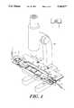
- FIG. 1is a perspective view showing the present invention wherein the dotted lines represent a microscope not claimed in this application;
- FIG. 2shows a plan view of the invention
- FIG. 3shows a side elevational cross section view of the present design taken along the lines 3--3 of FIG. 2;
- FIG. 4shows a side elevational view of the present invention taken along the lines 4--4 of FIG. 2.
- FIG. 1illustrates a preferred embodiment of the invention intended for illumination of a slide 12 from opposing longitudinal edges.
- the principle components of the slide illuminator 10comprise a U-shaped plate 15 supporting a pair of light source housings 20 and 21 in facing coplanar alignment.
- the housings 20 and 21are similar in construction. Each has a rectangular planar shape with proximal ends 24, 25 which are displaced downwardly from distal ends 27, 28 forming a shoulder 30 (not shown), 31 on the lower surface.
- Each housing 20 and 21contains light source means 35 and 36 (FIGS. 2, 3) each of which comprises a fiber optic bundle 39 and 40 having a diameter of 3.17 mm.
- the individual optical fibers each 0.05 mm in diameter, forming the bundles 39, 40are arranged in planar fan like arrays 41, 42 within housings 20, 21.
- the fan-like array 41, 42has a narrow end 43, 44 and a wide end 45, 46.
- the individual fibers at the wide end 45, 46each terminate and are polished for coplanar alignment with the respective proximal end 24, 25 of the housing 20, 21 within which it is located.
- the wide end 45, 46has preferably a width almost the width of the proximal end 24, 25 and is no wider than the slide to be used.
- the wide end 45, 46comprises approximately fourteen optical fiber in thickness.
- the narrow end of the fibersare gathered into ferrules 48 and 49, measuring 14.2 mm in length, which are coaxially aligned with leads 50 and 51, each having a diameter of 5.65 mm.
- Leads 50 and 51extend from the distal ends 27 and 28 of the housings 20 and 21 and are attached to an apparatus for transmitting light through the leads 50 and 51.
- the apparatuswhich is not shown is preferably a standard fiber optic light housing with a 150 watt halogen lamp which can accommodate two fiber bundles. A more intense lamp or one with larger capacity may also be used.
- the housings 20 and 21are each secured on the base 15 in longitudinal alignment with their respective proximal ends 24 25 in parallel facing relation.
- the housing 20is preferably secured on the base 15 by screws 55, 56.
- the screws 55, 56extend through slots 59, 60. Slots rather than holes are used to minimize manufacturing costs since housing 21 necessarily requires slots.
- Housing 21is secured on the base 15 by screws 63, 64 which project through slots 66, 67. The fit between screws 63, 64 and slots 66, 67, is loose which permits the housing 21 to slide reciprocally to and away from housing 20.
- a helical spring 65 extending longitudinally and symmetrically below the housing 21has one end 68 engaged in a recess 72 in the shoulder 31 and the other end 69 engaged in a recess 73, in a rear wall 75 in which the housing 21 slides.
- a slide 12may be held between stationary housing 20 and sliding housing 21.
- the wide ends 45, 46 of the fibersabut edges 78 and 79 of a slide 12 positioned in the plate 15.
- the height and length of the wide end 45, 46 of the fiber optic array 41, 42is less than the corresponding dimensions of the ends of the slide 12.
- the dimensions of the wide ends 45, 46should be approximately 20.3 mm long and 0.7 mm high.
- the plate 15is secured to a microscope 80, as shown in FIG. 1, by spaced stage screws 82 and 83 on standard microscopes which extend through screw slots 85 and 86.
- the plate 15also has a disengagement means 89 to permit removal of the slide 12 from between the housings 20 and 21.
- the disengagement means 89comprises a sloped step having a proximal end 91 which is adopted to engage a lateral edge 92 of the slide 12. This means 89 permits a user to remove the slide 12 without having to grip the slide itself.
- the slide 12may be pushed outwardly from the slide illuminator 10 under finger pressure.
- the lateral edge 92is higher than the proximal end 91 of the disengagement means 89 which exposes a portion of the lateral edge 92 for manual disengagement.
- the sloped disengagement means 89also minimizes contact when rotating microscope optics.
- the illuminator in the preferred embodimentis used with a 1 ⁇ 3 inch standard slide 12 in longitudinal alignment with the light source housings 20 and 21, this is not meant to limit the scope of the claims.
- the long edge of the slidemay be engaged by the housings in a modification of the invention.
- the inventioncontemplates modifications in which the slide is illuminated and gripped from adjacent perpendicular edges.
- the present inventionmay be modified for use with 2 ⁇ 3 inch slides which are common in many medical procedures. Illumination, while preferred to extend from a minimum of two sides, may be limited to one side. Thus, various combinations and permutations with respect to the lengths and widths of the slide, the number of light sources attached, and the positions of the light source housings are contemplated.
- specimensare permanently mounted in a transparent medium which has an index of refraction similar to glass.
- the specimen 95is mounted beneath coverslip 93 in a transparent medium 96.
- Similar refractive indices of the slide, medium and cover slipallows light to travel through the medium 96 to the upper surface of the coverslip 93.
- Some of the light traveling toward the coverslip 93reflects off the specimen 95 and back toward the coverslip 93.
- the angle of the light returning toward the coverslip 93is less than the critical angle, the light will refract through the coverslip 93 into the air and into the objective lens of the microscope, arrow B.
- the only light which has the opportunity of reaching the lensis light which bounces off the specimen or is significantly refracted by it. This creates the intense illumination of the specimen while maintaining a darkfield.
Landscapes
- Physics & Mathematics (AREA)
- General Physics & Mathematics (AREA)
- Optics & Photonics (AREA)
- Chemical & Material Sciences (AREA)
- Analytical Chemistry (AREA)
- Microscoopes, Condenser (AREA)
Abstract
Description
Claims (10)
Priority Applications (1)
| Application Number | Priority Date | Filing Date | Title |
|---|---|---|---|
| US07/806,107US5249077A (en) | 1991-12-12 | 1991-12-12 | Darkfield illuminator for a microscope slide |
Applications Claiming Priority (1)
| Application Number | Priority Date | Filing Date | Title |
|---|---|---|---|
| US07/806,107US5249077A (en) | 1991-12-12 | 1991-12-12 | Darkfield illuminator for a microscope slide |
Publications (1)
| Publication Number | Publication Date |
|---|---|
| US5249077Atrue US5249077A (en) | 1993-09-28 |
Family
ID=25193338
Family Applications (1)
| Application Number | Title | Priority Date | Filing Date |
|---|---|---|---|
| US07/806,107Expired - LifetimeUS5249077A (en) | 1991-12-12 | 1991-12-12 | Darkfield illuminator for a microscope slide |
Country Status (1)
| Country | Link |
|---|---|
| US (1) | US5249077A (en) |
Cited By (49)
| Publication number | Priority date | Publication date | Assignee | Title |
|---|---|---|---|---|
| US5570228A (en)* | 1991-04-19 | 1996-10-29 | Edge Scientific Instrument Company Llc | Fiber optic illumination system and method for a high definition light microscope |
| WO1997005516A1 (en)* | 1995-07-31 | 1997-02-13 | Leica Mikroskopie Und Systeme Gmbh | Object holder for thin object carriers |
| US5781338A (en)* | 1994-11-17 | 1998-07-14 | Carl Zeiss Stiftung | Microscope stage |
| US5831763A (en)* | 1995-06-23 | 1998-11-03 | Meyer Instruments Inc. | Holder for high resolution sample imaging |
| US6181471B1 (en)* | 1997-12-02 | 2001-01-30 | Mitutoyo Corporation | Illuminating system for image processing measuring apparatus |
| US6180415B1 (en) | 1997-02-20 | 2001-01-30 | The Regents Of The University Of California | Plasmon resonant particles, methods and apparatus |
| US6344272B1 (en) | 1997-03-12 | 2002-02-05 | Wm. Marsh Rice University | Metal nanoshells |
| US6394409B1 (en)* | 2000-01-14 | 2002-05-28 | Taiwan Semiconductor Manufacturing Company, Ltd. | Real time observable sample mounting fixture |
| US6424461B1 (en)* | 2000-03-10 | 2002-07-23 | Hirox Co., Ltd. | Apparatus for observing interior from an ultramicropore space |
| EP1196939A4 (en)* | 1999-07-01 | 2002-09-18 | Gen Nanotechnology Llc | Object inspection and/or modification system and method |
| US20020135755A1 (en)* | 1994-07-28 | 2002-09-26 | Kley Victor B. | Scanning probe microscope assembly |
| US6620623B1 (en) | 2002-05-06 | 2003-09-16 | The University Of Chicago | Biochip reader with enhanced illumination and bioarray positioning apparatus |
| US6645517B2 (en) | 1998-03-11 | 2003-11-11 | William Rice Marsh Rice University | Temperature-sensitive polymer/nanoshell composites for photothermally modulated drug delivery |
| WO2003100497A1 (en)* | 2002-05-23 | 2003-12-04 | Erhard Wendlandt | Lighting for a microscope |
| US20040027659A1 (en)* | 2002-08-08 | 2004-02-12 | Messerschmidt Robert G. | Sample holder |
| US6699724B1 (en) | 1998-03-11 | 2004-03-02 | Wm. Marsh Rice University | Metal nanoshells for biosensing applications |
| US6752008B1 (en) | 2001-03-08 | 2004-06-22 | General Nanotechnology Llc | Method and apparatus for scanning in scanning probe microscopy and presenting results |
| US6787768B1 (en) | 2001-03-08 | 2004-09-07 | General Nanotechnology Llc | Method and apparatus for tool and tip design for nanomachining and measurement |
| US6802646B1 (en) | 2001-04-30 | 2004-10-12 | General Nanotechnology Llc | Low-friction moving interfaces in micromachines and nanomachines |
| US6813937B2 (en) | 2001-11-28 | 2004-11-09 | General Nanotechnology Llc | Method and apparatus for micromachines, microstructures, nanomachines and nanostructures |
| US6852252B2 (en) | 1997-03-12 | 2005-02-08 | William Marsh Rice University | Use of metalnanoshells to impede the photo-oxidation of conjugated polymer |
| US6865927B1 (en) | 2001-01-30 | 2005-03-15 | General Nanotechnology Llc | Sharpness testing of micro-objects such as miniature diamond tool tips |
| US6880388B1 (en) | 2001-03-08 | 2005-04-19 | General Nanotechnology Llc | Active cantilever for nanomachining and metrology |
| DE10350472A1 (en)* | 2003-10-29 | 2005-07-07 | Carl Zeiss Jena Gmbh | Light microscope for dark field microscopy has aperture module which does not allow a light beam running parallel to the optical axis to pass through |
| US6998689B2 (en) | 2002-09-09 | 2006-02-14 | General Nanotechnology Llc | Fluid delivery for scanning probe microscopy |
| EP0989911A4 (en)* | 1997-06-18 | 2006-03-01 | Univ California | Specimen illumination apparatus with optical cavity for dark field illumination and methods of use |
| US7042828B2 (en) | 1995-07-24 | 2006-05-09 | General Nanotechnology Llc | Nanometer scale data storage device and associated positioning system |
| US7045780B2 (en) | 1994-07-28 | 2006-05-16 | General Nanotechnology, Llc | Scanning probe microscopy inspection and modification system |
| US7053369B1 (en) | 2001-10-19 | 2006-05-30 | Rave Llc | Scan data collection for better overall data accuracy |
| US20060280404A1 (en)* | 2005-05-25 | 2006-12-14 | The University Of Vermont And State Agricultural College | Optical fiber microscopy launch system and method |
| US7196328B1 (en) | 2001-03-08 | 2007-03-27 | General Nanotechnology Llc | Nanomachining method and apparatus |
| US7253407B1 (en) | 2001-03-08 | 2007-08-07 | General Nanotechnology Llc | Active cantilever for nanomachining and metrology |
| US20090052021A1 (en)* | 2005-09-26 | 2009-02-26 | Hideo Mogami | Microscopic Cell Observation and Inspection System Using a Plurality of Observation Methods |
| US20090080186A1 (en)* | 2007-09-21 | 2009-03-26 | Gerhard Helmreich | Medical examination apparatus |
| US20090296083A1 (en)* | 2006-03-14 | 2009-12-03 | Saaski Elric W | Optical assay apparatus and methods |
| US20090325812A1 (en)* | 1996-07-29 | 2009-12-31 | Nanosphere, Inc. | Nanoparticles having oligonucleotides attached thereto and uses therefor |
| WO2010009852A3 (en)* | 2008-07-23 | 2010-04-01 | Carl Zeiss Laser Optics Gmbh | Microscope comprising a lens and dark field illumination device and method for the production thereof |
| US20100302632A1 (en)* | 2007-12-10 | 2010-12-02 | Herbert Luttenberger | Microscopic system |
| EP2290352A2 (en)* | 2009-08-31 | 2011-03-02 | Sony Corporation | Fluorescent image obtaining device, fluorescent image obtaining method and fluorescent image obtaining program |
| US20110136165A1 (en)* | 2007-01-22 | 2011-06-09 | Borivoj Vojnovic | Detecting objects |
| US20110280038A1 (en)* | 2010-05-12 | 2011-11-17 | Jeong Hwan J | Systems for and methods of illumination at a high optical solid angle |
| US20120092477A1 (en)* | 2010-10-18 | 2012-04-19 | Olympus America Inc. | Wide field microscopic imaging system and method |
| US8192686B2 (en)* | 2006-10-24 | 2012-06-05 | Korea Electro Technology Research Institute | Apparatus for and method of measuring bio-chips using uniform total internal reflection illumination |
| DE102011003568A1 (en)* | 2011-02-03 | 2012-08-09 | Leica Microsystems (Schweiz) Ag | Area light source for a transmitted light illumination device of a microscope |
| DE102011003569A1 (en)* | 2011-02-03 | 2012-08-09 | Leica Microsystems (Schweiz) Ag | Area light source for a transmitted light illumination device of a microscope |
| WO2013026708A1 (en)* | 2011-08-24 | 2013-02-28 | Carl Zeiss Ag | Sample holder |
| US20130050812A1 (en)* | 2011-08-31 | 2013-02-28 | Hon Hai Precision Industry Co., Ltd. | Stereomicroscope |
| CN104204771A (en)* | 2012-02-23 | 2014-12-10 | 赫斯托因德私人有限公司 | A digital imaging system for biopsy inspection |
| US9310302B2 (en) | 2009-10-12 | 2016-04-12 | Ventana Medical Systems, Inc. | Multi-modality contrast and brightfield context rendering for enhanced pathology determination and multi-analyte detection in tissue |
Citations (15)
| Publication number | Priority date | Publication date | Assignee | Title |
|---|---|---|---|---|
| US2118777A (en)* | 1937-10-02 | 1938-05-24 | Price Brothers Inc | Illuminated sign |
| US2827557A (en)* | 1955-11-02 | 1958-03-18 | Edwin A Neugass | Instrument lighting device |
| US3561145A (en)* | 1968-03-05 | 1971-02-09 | United States Radium Corp | Light distributing lens system |
| DE2316943A1 (en)* | 1973-03-01 | 1974-09-05 | Ciba Geigy Ag | METHOD AND DEVICE FOR GENERATING A RELIEF-LIKE CONTRAST IN THE MICROSCOPIC IMAGE OF A TRANSLUCENT PHASE OBJECT |
| US3892959A (en)* | 1973-11-02 | 1975-07-01 | Gte Automatic Electric Lab Inc | Edge-lighted panel arrangement |
| JPS5385446A (en)* | 1977-01-06 | 1978-07-27 | Mitsubishi Electric Corp | Lighting method of optical microscope |
| US4297032A (en)* | 1980-02-14 | 1981-10-27 | The United States Of America As Represented By The Secretary Of The Navy | Dark field surface inspection illumination technique |
| DE3216439A1 (en)* | 1982-05-03 | 1983-11-03 | Schott Glaswerke, 6500 Mainz | Arrangement for illuminating observing planes in optical instruments |
| US4460939A (en)* | 1980-10-17 | 1984-07-17 | Fuji Photo Optical Co., Ltd. | Device for producing a line of illumination |
| DE3417075A1 (en)* | 1984-05-09 | 1985-11-14 | Peter 3300 Braunschweig Stuht | Microscope having an illuminating device for reflected-light investigations |
| US4621911A (en)* | 1985-03-12 | 1986-11-11 | Carnegie-Mellon University | Standing wave luminescence microscopy |
| DE3620746A1 (en)* | 1986-06-20 | 1987-12-23 | Leitz Ernst Gmbh | Diaphragm for optical imaging systems |
| US4729067A (en)* | 1986-09-26 | 1988-03-01 | Mitsubishi Rayon Company Ltd. | Light diffusing device |
| US5005108A (en)* | 1989-02-10 | 1991-04-02 | Lumitex, Inc. | Thin panel illuminator |
| US5101325A (en)* | 1990-03-20 | 1992-03-31 | General Electric Company | Uniform illumination of large, thin surfaces particularly suited for automotive applications |
- 1991
- 1991-12-12USUS07/806,107patent/US5249077A/ennot_activeExpired - Lifetime
Patent Citations (15)
| Publication number | Priority date | Publication date | Assignee | Title |
|---|---|---|---|---|
| US2118777A (en)* | 1937-10-02 | 1938-05-24 | Price Brothers Inc | Illuminated sign |
| US2827557A (en)* | 1955-11-02 | 1958-03-18 | Edwin A Neugass | Instrument lighting device |
| US3561145A (en)* | 1968-03-05 | 1971-02-09 | United States Radium Corp | Light distributing lens system |
| DE2316943A1 (en)* | 1973-03-01 | 1974-09-05 | Ciba Geigy Ag | METHOD AND DEVICE FOR GENERATING A RELIEF-LIKE CONTRAST IN THE MICROSCOPIC IMAGE OF A TRANSLUCENT PHASE OBJECT |
| US3892959A (en)* | 1973-11-02 | 1975-07-01 | Gte Automatic Electric Lab Inc | Edge-lighted panel arrangement |
| JPS5385446A (en)* | 1977-01-06 | 1978-07-27 | Mitsubishi Electric Corp | Lighting method of optical microscope |
| US4297032A (en)* | 1980-02-14 | 1981-10-27 | The United States Of America As Represented By The Secretary Of The Navy | Dark field surface inspection illumination technique |
| US4460939A (en)* | 1980-10-17 | 1984-07-17 | Fuji Photo Optical Co., Ltd. | Device for producing a line of illumination |
| DE3216439A1 (en)* | 1982-05-03 | 1983-11-03 | Schott Glaswerke, 6500 Mainz | Arrangement for illuminating observing planes in optical instruments |
| DE3417075A1 (en)* | 1984-05-09 | 1985-11-14 | Peter 3300 Braunschweig Stuht | Microscope having an illuminating device for reflected-light investigations |
| US4621911A (en)* | 1985-03-12 | 1986-11-11 | Carnegie-Mellon University | Standing wave luminescence microscopy |
| DE3620746A1 (en)* | 1986-06-20 | 1987-12-23 | Leitz Ernst Gmbh | Diaphragm for optical imaging systems |
| US4729067A (en)* | 1986-09-26 | 1988-03-01 | Mitsubishi Rayon Company Ltd. | Light diffusing device |
| US5005108A (en)* | 1989-02-10 | 1991-04-02 | Lumitex, Inc. | Thin panel illuminator |
| US5101325A (en)* | 1990-03-20 | 1992-03-31 | General Electric Company | Uniform illumination of large, thin surfaces particularly suited for automotive applications |
Non-Patent Citations (2)
| Title |
|---|
| Temple, P. A., "Improved Dark-Field-Like Surface Inspection Technique Using Total Internal Reflection", SPIE, pp. 44-51, vol. 190, LASL Optics Conference (1979). |
| Temple, P. A., Improved Dark Field Like Surface Inspection Technique Using Total Internal Reflection , SPIE, pp. 44 51, vol. 190, LASL Optics Conference (1979).* |
Cited By (101)
| Publication number | Priority date | Publication date | Assignee | Title |
|---|---|---|---|---|
| US5570228A (en)* | 1991-04-19 | 1996-10-29 | Edge Scientific Instrument Company Llc | Fiber optic illumination system and method for a high definition light microscope |
| US20020135755A1 (en)* | 1994-07-28 | 2002-09-26 | Kley Victor B. | Scanning probe microscope assembly |
| US7615738B2 (en) | 1994-07-28 | 2009-11-10 | General Nanotechnology, Llc | Scanning probe microscope assembly and method for making spectrophotometric, near-field, and scanning probe measurements |
| US7091476B2 (en) | 1994-07-28 | 2006-08-15 | General Nanotechnology Llc | Scanning probe microscope assembly |
| US7485856B2 (en) | 1994-07-28 | 2009-02-03 | General Nanotechnology Llp | Scanning probe microscopy inspection and modification system |
| US7045780B2 (en) | 1994-07-28 | 2006-05-16 | General Nanotechnology, Llc | Scanning probe microscopy inspection and modification system |
| US5781338A (en)* | 1994-11-17 | 1998-07-14 | Carl Zeiss Stiftung | Microscope stage |
| US5831763A (en)* | 1995-06-23 | 1998-11-03 | Meyer Instruments Inc. | Holder for high resolution sample imaging |
| US7535817B2 (en) | 1995-07-24 | 2009-05-19 | General Nanotechnology, L.L.C. | Nanometer scale data storage device and associated positioning system |
| US7042828B2 (en) | 1995-07-24 | 2006-05-09 | General Nanotechnology Llc | Nanometer scale data storage device and associated positioning system |
| US5781337A (en)* | 1995-07-31 | 1998-07-14 | Leica Mikroskopie Und Systeme Gmbh | Object holder for thin slides |
| WO1997005516A1 (en)* | 1995-07-31 | 1997-02-13 | Leica Mikroskopie Und Systeme Gmbh | Object holder for thin object carriers |
| US8323888B2 (en) | 1996-07-29 | 2012-12-04 | Nanosphere, Inc. | Nanoparticles having oligonucleotides attached thereto and uses therefor |
| US20090325812A1 (en)* | 1996-07-29 | 2009-12-31 | Nanosphere, Inc. | Nanoparticles having oligonucleotides attached thereto and uses therefor |
| US7501288B2 (en) | 1997-02-20 | 2009-03-10 | Invitrogen Corporation | Plasmon resonant particles, methods and apparatus |
| US8309370B2 (en) | 1997-02-20 | 2012-11-13 | The Regents Of The University Of California | Plasmon resonant particles, methods and apparatus |
| US20010002315A1 (en)* | 1997-02-20 | 2001-05-31 | The Regents Of The University Of California | Plasmon resonant particles, methods and apparatus |
| US6180415B1 (en) | 1997-02-20 | 2001-01-30 | The Regents Of The University Of California | Plasmon resonant particles, methods and apparatus |
| US6685986B2 (en) | 1997-03-12 | 2004-02-03 | William Marsh Rice University | Metal nanoshells |
| US7371457B2 (en) | 1997-03-12 | 2008-05-13 | William Marsh Rich University | Nanoparticle comprising nanoshell of thickness less than the bulk electron mean free path of the shell material |
| US6852252B2 (en) | 1997-03-12 | 2005-02-08 | William Marsh Rice University | Use of metalnanoshells to impede the photo-oxidation of conjugated polymer |
| US20040214001A1 (en)* | 1997-03-12 | 2004-10-28 | William Marsh Rice University | Metal nanoshells |
| US6344272B1 (en) | 1997-03-12 | 2002-02-05 | Wm. Marsh Rice University | Metal nanoshells |
| EP0989911A4 (en)* | 1997-06-18 | 2006-03-01 | Univ California | Specimen illumination apparatus with optical cavity for dark field illumination and methods of use |
| US6181471B1 (en)* | 1997-12-02 | 2001-01-30 | Mitutoyo Corporation | Illuminating system for image processing measuring apparatus |
| DE19854722B4 (en)* | 1997-12-02 | 2016-05-12 | Mitutoyo Corp. | Illumination system for an image processing measuring device |
| US10610995B2 (en) | 1998-01-21 | 2020-04-07 | Victor B. Kley | Method and apparatus for nanolapping |
| US6645517B2 (en) | 1998-03-11 | 2003-11-11 | William Rice Marsh Rice University | Temperature-sensitive polymer/nanoshell composites for photothermally modulated drug delivery |
| US6699724B1 (en) | 1998-03-11 | 2004-03-02 | Wm. Marsh Rice University | Metal nanoshells for biosensing applications |
| US20050130324A1 (en)* | 1998-03-11 | 2005-06-16 | William Marsh Rice University | Metal nanoshells for biosensing applications |
| EP1196939A4 (en)* | 1999-07-01 | 2002-09-18 | Gen Nanotechnology Llc | Object inspection and/or modification system and method |
| US7109482B2 (en) | 1999-07-01 | 2006-09-19 | General Nanotechnology Llc | Object inspection and/or modification system and method |
| US6394409B1 (en)* | 2000-01-14 | 2002-05-28 | Taiwan Semiconductor Manufacturing Company, Ltd. | Real time observable sample mounting fixture |
| US6424461B1 (en)* | 2000-03-10 | 2002-07-23 | Hirox Co., Ltd. | Apparatus for observing interior from an ultramicropore space |
| US6931710B2 (en) | 2001-01-30 | 2005-08-23 | General Nanotechnology Llc | Manufacturing of micro-objects such as miniature diamond tool tips |
| US6865927B1 (en) | 2001-01-30 | 2005-03-15 | General Nanotechnology Llc | Sharpness testing of micro-objects such as miniature diamond tool tips |
| US6923044B1 (en) | 2001-03-08 | 2005-08-02 | General Nanotechnology Llc | Active cantilever for nanomachining and metrology |
| US6880388B1 (en) | 2001-03-08 | 2005-04-19 | General Nanotechnology Llc | Active cantilever for nanomachining and metrology |
| US7947952B1 (en) | 2001-03-08 | 2011-05-24 | General Nanotechnology Llc | Nanomachining method and apparatus |
| US6752008B1 (en) | 2001-03-08 | 2004-06-22 | General Nanotechnology Llc | Method and apparatus for scanning in scanning probe microscopy and presenting results |
| US7137292B1 (en) | 2001-03-08 | 2006-11-21 | General Nanotechnology Llc | Active cantilever for nanomachining and metrology |
| US6787768B1 (en) | 2001-03-08 | 2004-09-07 | General Nanotechnology Llc | Method and apparatus for tool and tip design for nanomachining and measurement |
| US7178387B1 (en) | 2001-03-08 | 2007-02-20 | General Nanotechnology Llc | Method and apparatus for scanning in scanning probe microscopy and presenting results |
| US7196328B1 (en) | 2001-03-08 | 2007-03-27 | General Nanotechnology Llc | Nanomachining method and apparatus |
| US7253407B1 (en) | 2001-03-08 | 2007-08-07 | General Nanotechnology Llc | Active cantilever for nanomachining and metrology |
| US6802646B1 (en) | 2001-04-30 | 2004-10-12 | General Nanotechnology Llc | Low-friction moving interfaces in micromachines and nanomachines |
| US7547882B2 (en) | 2001-10-19 | 2009-06-16 | Rave Llc | Scan data collection for better overall data accurancy |
| US7053369B1 (en) | 2001-10-19 | 2006-05-30 | Rave Llc | Scan data collection for better overall data accuracy |
| US7266998B2 (en) | 2001-11-28 | 2007-09-11 | General Nanotechnology Llc | Method and apparatus for micromachines, microstructures, nanomachines and nanostructures |
| US6813937B2 (en) | 2001-11-28 | 2004-11-09 | General Nanotechnology Llc | Method and apparatus for micromachines, microstructures, nanomachines and nanostructures |
| US7631549B1 (en) | 2001-11-28 | 2009-12-15 | General Nanotechnology Llc | Method and apparatus for micromachines, microstructures, nanomachines and nanostructures |
| US9075082B2 (en) | 2002-03-07 | 2015-07-07 | Victor B. Kley | Fluid delivery for scanning probe microscopy |
| US20040077099A1 (en)* | 2002-05-06 | 2004-04-22 | The University Of Chicago | Biochip reader with enhanced illumination and bioarray positioning apparatus |
| US7288227B2 (en) | 2002-05-06 | 2007-10-30 | Uchicago Argonne Llc | Biochip reader with enhanced illumination and bioarray positioning apparatus |
| US6620623B1 (en) | 2002-05-06 | 2003-09-16 | The University Of Chicago | Biochip reader with enhanced illumination and bioarray positioning apparatus |
| WO2003100497A1 (en)* | 2002-05-23 | 2003-12-04 | Erhard Wendlandt | Lighting for a microscope |
| WO2004015387A3 (en)* | 2002-08-08 | 2004-04-29 | Inlight Solutions Inc | Sample holder |
| US20040027659A1 (en)* | 2002-08-08 | 2004-02-12 | Messerschmidt Robert G. | Sample holder |
| US6998689B2 (en) | 2002-09-09 | 2006-02-14 | General Nanotechnology Llc | Fluid delivery for scanning probe microscopy |
| DE10350472A1 (en)* | 2003-10-29 | 2005-07-07 | Carl Zeiss Jena Gmbh | Light microscope for dark field microscopy has aperture module which does not allow a light beam running parallel to the optical axis to pass through |
| US20090028505A1 (en)* | 2005-05-25 | 2009-01-29 | University Of Vermont And State Agricultural College | Optical Fiber Microscopy Launch System and Method |
| US20090245731A1 (en)* | 2005-05-25 | 2009-10-01 | University Of Vermont And State Agricultural College | Optical Fiber Microscopy Launch System and Method |
| US7616853B2 (en) | 2005-05-25 | 2009-11-10 | The University Of Vermont And State Agricultural College | Optical fiber microscopy launch system and method |
| WO2006127901A3 (en)* | 2005-05-25 | 2009-04-16 | Univ Vermont | Optical fiber microscopy launch system and method |
| US7433563B2 (en)* | 2005-05-25 | 2008-10-07 | University Of Vermont And State Agricultural College | Optical fiber microscopy launch system and method |
| US20060280404A1 (en)* | 2005-05-25 | 2006-12-14 | The University Of Vermont And State Agricultural College | Optical fiber microscopy launch system and method |
| US7711225B2 (en)* | 2005-05-25 | 2010-05-04 | University Of Vermont And State Agricultural College | Optical fiber microscopy launch system and method |
| US20100209048A1 (en)* | 2005-05-25 | 2010-08-19 | University Of Vermont And State Agricultural College | Optical Fiber Microscopy Launch System and Method |
| US7885498B2 (en)* | 2005-05-25 | 2011-02-08 | University Of Vermont And State Agricultural College | Optical fiber microscopy launch system and method |
| US7706060B2 (en)* | 2005-09-26 | 2010-04-27 | National University Corporation Hamamatsu University School Of Medicine | Microscopic cell observation and inspection system using a plurality of observation methods |
| JP5087745B2 (en)* | 2005-09-26 | 2012-12-05 | 国立大学法人浜松医科大学 | Microscopic cell observation / inspection system using multiple observation techniques |
| US20090052021A1 (en)* | 2005-09-26 | 2009-02-26 | Hideo Mogami | Microscopic Cell Observation and Inspection System Using a Plurality of Observation Methods |
| US7651869B2 (en) | 2006-03-14 | 2010-01-26 | Research International, Inc. | Optical assay apparatus and methods |
| US20090296083A1 (en)* | 2006-03-14 | 2009-12-03 | Saaski Elric W | Optical assay apparatus and methods |
| US8192686B2 (en)* | 2006-10-24 | 2012-06-05 | Korea Electro Technology Research Institute | Apparatus for and method of measuring bio-chips using uniform total internal reflection illumination |
| US20110136165A1 (en)* | 2007-01-22 | 2011-06-09 | Borivoj Vojnovic | Detecting objects |
| US9212985B2 (en) | 2007-01-22 | 2015-12-15 | Isis Innovation Limited | Detecting objects |
| US8083389B2 (en)* | 2007-09-21 | 2011-12-27 | Siemens Aktiengesellschaft | Medical examination apparatus |
| US20090080186A1 (en)* | 2007-09-21 | 2009-03-26 | Gerhard Helmreich | Medical examination apparatus |
| US20100302632A1 (en)* | 2007-12-10 | 2010-12-02 | Herbert Luttenberger | Microscopic system |
| WO2010009852A3 (en)* | 2008-07-23 | 2010-04-01 | Carl Zeiss Laser Optics Gmbh | Microscope comprising a lens and dark field illumination device and method for the production thereof |
| EP2290352A2 (en)* | 2009-08-31 | 2011-03-02 | Sony Corporation | Fluorescent image obtaining device, fluorescent image obtaining method and fluorescent image obtaining program |
| US9310302B2 (en) | 2009-10-12 | 2016-04-12 | Ventana Medical Systems, Inc. | Multi-modality contrast and brightfield context rendering for enhanced pathology determination and multi-analyte detection in tissue |
| US20110280038A1 (en)* | 2010-05-12 | 2011-11-17 | Jeong Hwan J | Systems for and methods of illumination at a high optical solid angle |
| US8542274B2 (en)* | 2010-10-18 | 2013-09-24 | Olympus America Inc. | Wide field microscopic imaging system and method |
| US20120092477A1 (en)* | 2010-10-18 | 2012-04-19 | Olympus America Inc. | Wide field microscopic imaging system and method |
| JP2012164651A (en)* | 2011-02-03 | 2012-08-30 | Leica Microsystems (Schweiz) Ag | Flat panel type light source for transmission lighting device for microscope |
| DE102011003568A1 (en)* | 2011-02-03 | 2012-08-09 | Leica Microsystems (Schweiz) Ag | Area light source for a transmitted light illumination device of a microscope |
| DE102011003568B4 (en)* | 2011-02-03 | 2013-03-21 | Leica Microsystems (Schweiz) Ag | Area light source for a transmitted light illumination device of a microscope |
| US8469572B2 (en) | 2011-02-03 | 2013-06-25 | Leica Microsystems (Schweiz) Ag | Flat panel light source for a transillumination device of a microscope |
| US8534893B2 (en) | 2011-02-03 | 2013-09-17 | Leica Microsystems (Schweiz) Ag | Flat panel light source for a transillumination device of a microscope |
| CN102707422A (en)* | 2011-02-03 | 2012-10-03 | 徕卡显微系统(瑞士)股份公司 | Flat panel light source for a transillumination device of a microscope |
| DE102011003569B4 (en)* | 2011-02-03 | 2013-03-21 | Leica Microsystems (Schweiz) Ag | Area light source for a transmitted light illumination device of a microscope |
| CN102707422B (en)* | 2011-02-03 | 2015-06-03 | 徕卡显微系统(瑞士)股份公司 | Flat panel light source for a transillumination device of a microscope |
| JP2012164635A (en)* | 2011-02-03 | 2012-08-30 | Leica Microsystems (Schweiz) Ag | Flat panel type light source for transmission lighting device for microscope |
| DE102011003569A1 (en)* | 2011-02-03 | 2012-08-09 | Leica Microsystems (Schweiz) Ag | Area light source for a transmitted light illumination device of a microscope |
| WO2013026708A1 (en)* | 2011-08-24 | 2013-02-28 | Carl Zeiss Ag | Sample holder |
| US8873141B2 (en)* | 2011-08-31 | 2014-10-28 | Tsinghua University | Stereomicroscope |
| US20130050812A1 (en)* | 2011-08-31 | 2013-02-28 | Hon Hai Precision Industry Co., Ltd. | Stereomicroscope |
| EP2817610A4 (en)* | 2012-02-23 | 2015-09-30 | Histoindex Pte Ltd | A digital imaging system for biopsy inspection |
| CN104204771A (en)* | 2012-02-23 | 2014-12-10 | 赫斯托因德私人有限公司 | A digital imaging system for biopsy inspection |
Similar Documents
| Publication | Publication Date | Title |
|---|---|---|
| US5249077A (en) | Darkfield illuminator for a microscope slide | |
| US10345303B2 (en) | Image analysis and measurement of biological samples | |
| US9279768B2 (en) | Fluorescence reader | |
| CA2294005C (en) | Specimen illumination apparatus with optical cavity for dark field illumination and methods of use | |
| EP0857316B1 (en) | Dark field illuminator ringlight adaptor | |
| US7218810B2 (en) | Biochemical assay detection in a liquid receptacle using a fiber optic exciter | |
| CA2261530C (en) | Photometric readhead with light-shaping plate | |
| KR20000053341A (en) | Analytical apparatus | |
| CA2415376A1 (en) | Scanning system and method for scanning a plurality of samples | |
| AU2002336771C1 (en) | Imaging of microarrays using fiber optic exciter | |
| US7376304B2 (en) | Biochemical assay detection using a fiber optic exciter | |
| ATE18468T1 (en) | ILLUMINATION DEVICE FOR MICROSCOPES. | |
| AU2002336771A1 (en) | Imaging of microarrays using fiber optic exciter | |
| JPH0560538A (en) | Optical measurement machine | |
| WO1998023945A1 (en) | Perimeter light detection apparatus for enhanced collection of radiation | |
| WO1998023945A9 (en) | Perimeter light detection apparatus for enhanced collection of radiation | |
| US4209226A (en) | Optical viewing instrument including capillary tube and holder | |
| US11982802B2 (en) | Device and method for performing total internal reflection scattering measurement | |
| US3490828A (en) | Microscope with means for varying the direction of light to the object to be viewed | |
| US6172751B1 (en) | High efficiency reflectometry illuminator and collector system | |
| US5760894A (en) | Liquid sample analysis in an optical fourier transform system | |
| CN216717604U (en) | Multi-light-source single-light-path multi-prism optical splitting imaging system | |
| GB2085611A (en) | Refractometer for Testing Gemstones | |
| EP0712011A1 (en) | Optical index matching system | |
| RU2413263C1 (en) | Reflected-light microscope |
Legal Events
| Date | Code | Title | Description |
|---|---|---|---|
| AS | Assignment | Owner name:MICROVIDEO INSTRUMENTS, INC., MASSACHUSETTS Free format text:ASSIGNMENT OF ASSIGNORS INTEREST;ASSIGNORS:LARONGA, VICTOR;THORBURN, STANLEY B.;REEL/FRAME:006573/0905 Effective date:19930525 | |
| STCF | Information on status: patent grant | Free format text:PATENTED CASE | |
| FEPP | Fee payment procedure | Free format text:PAYOR NUMBER ASSIGNED (ORIGINAL EVENT CODE: ASPN); ENTITY STATUS OF PATENT OWNER: SMALL ENTITY | |
| FPAY | Fee payment | Year of fee payment:4 | |
| FEPP | Fee payment procedure | Free format text:PAYER NUMBER DE-ASSIGNED (ORIGINAL EVENT CODE: RMPN); ENTITY STATUS OF PATENT OWNER: SMALL ENTITY Free format text:PAYOR NUMBER ASSIGNED (ORIGINAL EVENT CODE: ASPN); ENTITY STATUS OF PATENT OWNER: SMALL ENTITY | |
| FEPP | Fee payment procedure | Free format text:PAYOR NUMBER ASSIGNED (ORIGINAL EVENT CODE: ASPN); ENTITY STATUS OF PATENT OWNER: SMALL ENTITY Free format text:PAYER NUMBER DE-ASSIGNED (ORIGINAL EVENT CODE: RMPN); ENTITY STATUS OF PATENT OWNER: SMALL ENTITY | |
| FEPP | Fee payment procedure | Free format text:PAYER NUMBER DE-ASSIGNED (ORIGINAL EVENT CODE: RMPN); ENTITY STATUS OF PATENT OWNER: SMALL ENTITY | |
| FPAY | Fee payment | Year of fee payment:8 | |
| FPAY | Fee payment | Year of fee payment:12 | |
| FEPP | Fee payment procedure | Free format text:PAYER NUMBER DE-ASSIGNED (ORIGINAL EVENT CODE: RMPN); ENTITY STATUS OF PATENT OWNER: SMALL ENTITY Free format text:PAYOR NUMBER ASSIGNED (ORIGINAL EVENT CODE: ASPN); ENTITY STATUS OF PATENT OWNER: SMALL ENTITY |