US5248880A - Detector system for detecting the occurrence of welding - Google Patents
Detector system for detecting the occurrence of weldingDownload PDFInfo
- Publication number
- US5248880A US5248880AUS07/814,372US81437291AUS5248880AUS 5248880 AUS5248880 AUS 5248880AUS 81437291 AUS81437291 AUS 81437291AUS 5248880 AUS5248880 AUS 5248880A
- Authority
- US
- United States
- Prior art keywords
- signal
- output
- threshold
- detector
- intensity
- Prior art date
- Legal status (The legal status is an assumption and is not a legal conclusion. Google has not performed a legal analysis and makes no representation as to the accuracy of the status listed.)
- Expired - Lifetime
Links
Images


Classifications
- A—HUMAN NECESSITIES
- A61—MEDICAL OR VETERINARY SCIENCE; HYGIENE
- A61F—FILTERS IMPLANTABLE INTO BLOOD VESSELS; PROSTHESES; DEVICES PROVIDING PATENCY TO, OR PREVENTING COLLAPSING OF, TUBULAR STRUCTURES OF THE BODY, e.g. STENTS; ORTHOPAEDIC, NURSING OR CONTRACEPTIVE DEVICES; FOMENTATION; TREATMENT OR PROTECTION OF EYES OR EARS; BANDAGES, DRESSINGS OR ABSORBENT PADS; FIRST-AID KITS
- A61F9/00—Methods or devices for treatment of the eyes; Devices for putting in contact-lenses; Devices to correct squinting; Apparatus to guide the blind; Protective devices for the eyes, carried on the body or in the hand
- A61F9/04—Eye-masks ; Devices to be worn on the face, not intended for looking through; Eye-pads for sunbathing
- A61F9/06—Masks, shields or hoods for welders
- A61F9/065—Masks, shields or hoods for welders use of particular optical filters
- A61F9/067—Masks, shields or hoods for welders use of particular optical filters with variable transmission
- A—HUMAN NECESSITIES
- A61—MEDICAL OR VETERINARY SCIENCE; HYGIENE
- A61F—FILTERS IMPLANTABLE INTO BLOOD VESSELS; PROSTHESES; DEVICES PROVIDING PATENCY TO, OR PREVENTING COLLAPSING OF, TUBULAR STRUCTURES OF THE BODY, e.g. STENTS; ORTHOPAEDIC, NURSING OR CONTRACEPTIVE DEVICES; FOMENTATION; TREATMENT OR PROTECTION OF EYES OR EARS; BANDAGES, DRESSINGS OR ABSORBENT PADS; FIRST-AID KITS
- A61F9/00—Methods or devices for treatment of the eyes; Devices for putting in contact-lenses; Devices to correct squinting; Apparatus to guide the blind; Protective devices for the eyes, carried on the body or in the hand
- A61F9/04—Eye-masks ; Devices to be worn on the face, not intended for looking through; Eye-pads for sunbathing
- A61F9/06—Masks, shields or hoods for welders
- A61F9/061—Masks, shields or hoods for welders with movable shutters, e.g. filter discs; Actuating means therefor
- G—PHYSICS
- G01—MEASURING; TESTING
- G01J—MEASUREMENT OF INTENSITY, VELOCITY, SPECTRAL CONTENT, POLARISATION, PHASE OR PULSE CHARACTERISTICS OF INFRARED, VISIBLE OR ULTRAVIOLET LIGHT; COLORIMETRY; RADIATION PYROMETRY
- G01J1/00—Photometry, e.g. photographic exposure meter
- G01J1/02—Details
- G01J1/04—Optical or mechanical part supplementary adjustable parts
- G01J1/0407—Optical elements not provided otherwise, e.g. manifolds, windows, holograms, gratings
- G01J1/044—Optical elements not provided otherwise, e.g. manifolds, windows, holograms, gratings using shutters
- G—PHYSICS
- G01—MEASURING; TESTING
- G01J—MEASUREMENT OF INTENSITY, VELOCITY, SPECTRAL CONTENT, POLARISATION, PHASE OR PULSE CHARACTERISTICS OF INFRARED, VISIBLE OR ULTRAVIOLET LIGHT; COLORIMETRY; RADIATION PYROMETRY
- G01J1/00—Photometry, e.g. photographic exposure meter
- G01J1/10—Photometry, e.g. photographic exposure meter by comparison with reference light or electric value provisionally void
- G01J1/16—Photometry, e.g. photographic exposure meter by comparison with reference light or electric value provisionally void using electric radiation detectors
- G01J1/18—Photometry, e.g. photographic exposure meter by comparison with reference light or electric value provisionally void using electric radiation detectors using comparison with a reference electric value
- G—PHYSICS
- G01—MEASURING; TESTING
- G01J—MEASUREMENT OF INTENSITY, VELOCITY, SPECTRAL CONTENT, POLARISATION, PHASE OR PULSE CHARACTERISTICS OF INFRARED, VISIBLE OR ULTRAVIOLET LIGHT; COLORIMETRY; RADIATION PYROMETRY
- G01J1/00—Photometry, e.g. photographic exposure meter
- G01J1/42—Photometry, e.g. photographic exposure meter using electric radiation detectors
- G01J1/4204—Photometry, e.g. photographic exposure meter using electric radiation detectors with determination of ambient light
- G—PHYSICS
- G01—MEASURING; TESTING
- G01J—MEASUREMENT OF INTENSITY, VELOCITY, SPECTRAL CONTENT, POLARISATION, PHASE OR PULSE CHARACTERISTICS OF INFRARED, VISIBLE OR ULTRAVIOLET LIGHT; COLORIMETRY; RADIATION PYROMETRY
- G01J1/00—Photometry, e.g. photographic exposure meter
- G01J1/42—Photometry, e.g. photographic exposure meter using electric radiation detectors
- G01J1/44—Electric circuits
- G—PHYSICS
- G02—OPTICS
- G02F—OPTICAL DEVICES OR ARRANGEMENTS FOR THE CONTROL OF LIGHT BY MODIFICATION OF THE OPTICAL PROPERTIES OF THE MEDIA OF THE ELEMENTS INVOLVED THEREIN; NON-LINEAR OPTICS; FREQUENCY-CHANGING OF LIGHT; OPTICAL LOGIC ELEMENTS; OPTICAL ANALOGUE/DIGITAL CONVERTERS
- G02F1/00—Devices or arrangements for the control of the intensity, colour, phase, polarisation or direction of light arriving from an independent light source, e.g. switching, gating or modulating; Non-linear optics
- G02F1/01—Devices or arrangements for the control of the intensity, colour, phase, polarisation or direction of light arriving from an independent light source, e.g. switching, gating or modulating; Non-linear optics for the control of the intensity, phase, polarisation or colour
- G02F1/13—Devices or arrangements for the control of the intensity, colour, phase, polarisation or direction of light arriving from an independent light source, e.g. switching, gating or modulating; Non-linear optics for the control of the intensity, phase, polarisation or colour based on liquid crystals, e.g. single liquid crystal display cells
- G02F1/133—Constructional arrangements; Operation of liquid crystal cells; Circuit arrangements
- G02F1/13306—Circuit arrangements or driving methods for the control of single liquid crystal cells
- G02F1/13318—Circuits comprising a photodetector
- G—PHYSICS
- G01—MEASURING; TESTING
- G01J—MEASUREMENT OF INTENSITY, VELOCITY, SPECTRAL CONTENT, POLARISATION, PHASE OR PULSE CHARACTERISTICS OF INFRARED, VISIBLE OR ULTRAVIOLET LIGHT; COLORIMETRY; RADIATION PYROMETRY
- G01J1/00—Photometry, e.g. photographic exposure meter
- G01J1/02—Details
- G01J2001/0276—Protection
Definitions
- the present inventionrelates generally, as is indicated, to a circuit for detecting the presence of a welding arc or any industrial light hazard and use of such circuit as part of a driving circuit for a light shutter, such as a liquid crystal shutter and, more particularly, to a high speed driving circuit for a liquid crystal shutter operable to control transmission of light therethrough.
- a light shuttersuch as a liquid crystal shutter
- Such shutterssometimes are referred to as automatically darkening welding filters.
- the inventionis especially useful to provide both a fast response to rapid change in light intensity and a varying sensitivity in order to accommodate different and/or varying ambient light intensity levels.
- the inventionalso is especially useful to sense both continuous type and intermittent type welding, also referred to as TIG welding and MIG welding, respectively.
- a shutterrefers to a device for controlling intensity of electromagnetic energy or electromagnetic radiation that is being transmitted through the shutter.
- electromagnetic energyis in the form of light and more preferably is in the form of light (i.e., electromagnetic energy) that is in the visible spectrum as well as in the various infrared spectra and ultraviolet spectra, all collectively referred to as light below.
- controlmay be by way of graduated or analog control of intensity of transmitted light preferably without detrimentally affecting the image characteristics of such light.
- Such controlalso may be digital, i.e., on, off, and specific intermediate levels of transmission or intensity, etc.
- the shutter and the circuit of the inventionare used as an automatically darkening welding filter to protect the eyes of a welder during welding. It will be appreciated that the invention may be used for other signal detection purposes and the like, too.
- Exemplary liquid crystal shutters with which the driving circuit of the invention may be utilizedare disclosed in U.S. Pat. Nos. 4,385,806, 4,436,376, 4,540,243, and Re. 32,521 or in U.S. patent application Ser. No. 07/674,850 for "Liquid Crystal Lens Driver Electronics For Eye Protection and High Speed Shuttering".
- An example of such shuttersincludes a pair of linear (plane) polarizers, one being used as an input polarizer and the other as an output analyzer, and a variable liquid crystal optical retarder between the two polarizers.
- the plane of polarization (or relationships of the axes of elliptically polarized light) of the light transmitted through the retardercan be changed; and the intensity of light transmitted through the analyzer will be a function of the polarization direction (characteristics) of the light transmitted through the retarder.
- a shutter system which may employ such an exemplary liquid crystal shutteris disclosed in copending, commonly owned U.S. patent application Ser. No. 07/653,661 filed Feb. 8, 1991, for "Eye Protection System For Welding Helmets And The Like".
- the present inventionis useful to provide electrical power and to operate such a shutter system and the shutters mentioned in the preceding paragraph.
- Exemplary shutters which may be used in connection with thisare sold by OSD Envizion Company of Menlo Park, Calif.
- the terms “lens”, “welding lens”, and “welding filter”are used herein synonymously with “shutter” and as used herein means a device through which an image may be viewed usually without necessarily having any significant focusing or optical refraction characteristics.
- the lens or shutteris adjustable to control light, i.e., to increase or to decrease the amount of the incident light which is transmitted through the shutter.
- the shutterWhen welding is not occurring, the shutter may be substantially optically clear or transmissive or at least minimizes its attenuation of light. When welding is occurring, the shutter may be dark or closed to minimize the amount of light transmitted therethrough in order to protect the eyes of the person performing the welding. In both cases, though, the image characteristics of the light remain intact.
- a photosensitive devicemay be used to sense the intensity of light impinging in the area of the shutter so as to provide an input to the driving circuit for the shutter in order to control opening and closing thereof.
- the present inventionis especially useful for eye protection wherein detection of a bright light source and high speed protective shuttering are desired.
- Exemplary usesare in welding helmets, spectacles, goggles, and the like, as well as safety goggles for nuclear flash protection, for protection from hazards experienced by electric utility workers and for workers at furnace and electrical plant areas and at other places where bright light that could present a risk of injury may occur.
- the present inventionis useful in other non-eye protection fields such as where high speed detection and shuttering of light will provide for more comfortable operation of certain equipment such as high speed detection of headlights approaching from the rear for automatically dimming rear view mirrors in automobiles.
- the present inventionis also useful for protection and tuning of optical measurement equipment in a variety of laboratory, test and production environments.
- U.S. patent application Ser. No. 07/674,850discloses a photosensitive sensor circuit and driving circuit for use in automated welding lens systems with a sensor operational range that functions well in both indoor environments and outdoor environments, that automatically adjusts to the relatively gradual changes in ambient light compared to rapid changes due to initiation of a welding arc, flame, etc, and that operates relatively rapidly in order rapidly to operate the shutter driven thereby.
- Sensor devices prior to the invention disclosed in such patent applicationdid not adjust automatically to accommodate the change in ambient conditions, for example, when the door to a room is opened to allow bright sunlight to enter the room, and, therefore, such prior devices possibly falsely might trigger a detection of welding or impede proper sensitivity to welding in such a case.
- a manual adjustmentwas provided to accommodate particular ambient light conditions and also to accommodate the pulsed type or continuous type of light emitted during welding, e.g., during MIG welding or TIG welding, respectively.
- the present inventionprovides for automatic adjustment of the sensitivity to an incident signal intended to be detected, such as electromagnetic energy or electromagnetic radiation, especially light, or to some other input, relative to the magnitude, intensity, etc. of an ambient (or steady state) condition.
- an incident signal intended to be detectedsuch as electromagnetic energy or electromagnetic radiation, especially light, or to some other input, relative to the magnitude, intensity, etc. of an ambient (or steady state) condition.
- the inventionis directed to a detector circuit which automatically adjusts its sensitivity to a light flash relative to the intensity of ambient light.
- the present inventionis directed to a sensor and associated sensor circuitry which provide a wide sensitivity range which is fully automatically adjustable, and which has the ability to detect fast changes in light intensity.
- the sensor and sensor circuitryfurther have the ability to distinguish low power stable light generated by a small welding arc from bright ambient light or even direct sunlight.
- the present inventionprovides for automatic adjustment of a sensor circuit for a liquid crystal shutter driving circuit, such as that disclosed in U.S. patent application Ser. No. 07/674,850, to accommodate a wide variety of ambient light conditions, e.g., from indoor artificial light to outdoor bright sunlight, and to accommodate both pulsating and continuous type welding operations.
- the sensor circuitryadjusts fully automatically.
- the sensor circuitryWhen used in a welding lens power supply circuit (drive circuit) or other device, the sensor circuitry has a variable light input threshold and feedback sensitivity control. This variable threshold and feedback are provided to maintain high sensitivity in a wide range of ambient light conditions. A sharp rise in the ambient light level will cause the feedback operation of the sensor circuit to temporarily shut down. Welding arcs and other light hazards can be distinguished at their inception by the rapid rise in the detected light level. As soon as there is a significant drop in the light level (e.g., due to the welding arc being extinguished), the feedback operation of the sensor circuit is resumed.
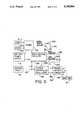
- FIG. 1is a schematic illustration of a welding helmet including a sensor circuit, liquid crystal lens assembly and driver circuit according to the invention
- FIG. 2is a schematic illustration of a sensor circuit of the present invention
- FIG. 3is a graph showing the relationship of the conduction or voltage output characteristic of the photodetector circuit in the sensor circuit of the invention.
- FIG. 4is a graph representing the relationship of voltage response of the photodetector circuit over time showing inception and cessation of welding;
- FIG. 5is a graph representing the relationship between the signal representing the intensity of incident light on the photodetector of the sensor circuit as compensated by a sensitivity feedback circuit thereof and a threshold signal developed in the sensor circuit;
- FIG. 6is a schematic electric circuit diagram of the drive circuit (also referred to as a driving circuit) which operates the liquid crystal lens assembly.
- FIG. 1a welding helmet I for wearing on the head of a person to protect the eyes 2 of a person from bright light emitted by a welding process represented as light source 3 is illustrated.
- a welding lens or liquid crystal shutter 10which includes a variable optical retarder 11 sandwiched between a pair of linear polarizers 12, 13.
- the optical axes of the polarizers 12, 13may be at right angles to each other and at 45 degrees to the optical axis of the retarder 11 as is described in the above-mentioned patents and patent application.
- the retarder 11may be of the type disclosed in the above-mentioned patents and patent applications.
- the shutter 10may be used as a lens in a welding helmet, goggles or other eye protection device as well as in other devices intended to be protected from light or other electromagnetic energy which can be attenuated by the shutter.
- the shutter 10may be a part of a welding lens system such as the ones disclosed in the above mentioned patent application.
- a power supply or drive circuit 14, such as one of those disclosed in the above mentioned patent applications, and especially the driving circuit described in Ser. No. 07/674,850is operative to provide an electric field of prescribed voltage to the retarder 11 to determine how much of the input or incident light 15 from the source 3 and/or other sources, e.g., ambient light, is transmitted as output light 16 by the shutter 10.
- input light 15is at relatively low intensity or at least is not at the intensity of welding light, and substantially all of the light possible will be transmitted by the shutter 10, which then is in the clear state, as output light 16.
- the drive circuit 14operates the shutter 10 to reduce substantially below 50% the relative intensity of the output light 16, i.e., relative to the intensity of the incident light 15, e.g., to several percent, preferably less than 1%, and more preferably to even less.
- drive circuit 14 and sensor circuit 18 thereofare disclosed for use with an automatically darkening welding filter and welding helmet, goggles, or the like, it will be appreciated that they also may be used for other purposes to detect light and/or other inputs. Also, while a preferred shutter 10 is disclosed herein, the features of the circuits 14 and 18 may be used with other shutters to control light transmission.
- the sensor power supply 18includes an input circuit 20, which also may be the input electrical power provided to the drive power supply 14.
- the input circuit 20includes a 9 volt electrical storage battery 21, which is connected between a positive terminal, electrical line or connection 22 and a negative or relative ground potential terminal, line or connection designated 23.
- Other types of input power supplies 20also may be used having larger or smaller magnitudes than the 9 volt battery indicated.
- the input power supply 20may be provided via a transformer connection and/or via a direct connection to a source of electrical power, such as a battery, alternator, generator, the electrical lines from the utility company, etc.
- reference to lines, leads, conductors, etc.essentially means an electrically conductive path from one place or device to another regardless of whether a discrete electrical wire is used for effecting the electrical connection; a printed circuit electrically conductive trace on a printed circuit board is employed to make that connection; implementation is within an integrated circuit where the connection is made; etc., without limitation.
- reference to logic 0 signal, ground reference potential, negative signal, etc.typically means the same, for example, a connection to the ground terminal 23 associated with the battery 21, or a typical logic 0 signal, as is well known in the electronics and digital circuitry field.
- Reference to a logic 1 signaltypically means a positive (or negative, as the case may be) signal, such as that at the positive side of the battery 21, such as 9 volts, or some other relatively reduced value, but in any event a value that is distinguishable from the logic 0 signal level.
- the sensor circuit 18includes a pair of detector circuits 200, 201, which are electrically connected together via lines 202, 203 to inputs of a NAND gate 204. Inputs to lines 202, 203 are via a pair of inverters 205, 206 so that such inverters combined with the NAND gate 204 form an OR gate.
- the two detector circuits 200, 201preferably are substantially identical, are independent of each other and, thus, are redundant. If either detects a prescribed input, such as occurrence of welding or some other input intended to be detected, it can operate and is intended to operate the drive circuit 14 accordingly.
- Such operation according to the best mode of the inventionis to drive the shutter to a darkened shade condition to protect the eyes of a welder from the light emitted by the welding arc, flame, etc., for example.
- the detector circuits 200, 201are separate, equal and redundant, they can both provide the same function without having to be carefully calibrated relative to each other; eliminating such a calibration requirement can provide a substantial cost savings in parts cost and in manufacturing of the sensor circuit 18.
- a time delay circuit 210which includes a resistor 211 and a capacitor 212, is coupled between the battery positive terminal 22 and ground 23.
- the output from the NAND gate 204is coupled via a diode 213 to the junction 214 of resistor 211 and capacitor 212.
- the time delay circuit 210provides a dark to clear delay time of, for example, one fourth second (or other time period, such as from about 0.1 second to about 0.5 second) so that a brief interruption in the welding light, e.g., during AC type MIG welding, or some other brief loss of light detection will not allow the shutter 10 to transition from dark state to clear state.
- the output from the AND gate 204effectively is provided to input of an inverter 215, which alteratively may be a Schmitt trigger circuit.
- the output line 216 from the inverteris coupled to the drive circuit 14 to provide a signal thereto indicating whether the shutter 10 is to be in the clear state (when welding is not occurring) or in the dark state (to protect the welder's eyes from bright welding light).
- Exemplary uses of the signal on line 216 in the drive circuit 14are to cause the variable retarder 11 in the shutter 10 to be driven at maximum voltage to achieve dark state, at a reduced voltage to maintain a dark state or at a still further reduced voltage for a clear state; to determine whether the shutter is to be driven by a relatively lower or relatively higher frequency; and to reset an automatic time out power saver counter circuit; all of which are described in application Ser. No. 07/674,850 and are briefly summarized herein.
- the output from the NAND gate 204is logic 1 blocking the diode 213; and it is intended that the signal at junction 214 will be a logic 1 or relatively positive voltage then so that the output from the inverter 215 provided on line 216 will be a logic 0 or relative ground signal.
- the signal at the output from the NAND gate 204transitions from a logic 1 level to a logic 0 level (or relative ground), which causes the signal at junction 214 rapidly, e.g., in less than about one microsecond (or in any event preferably within a few microseconds, i.e., much faster than the milliseconds time frame within which the sensitivity feedback circuit 221 responds), to be pulled to a logic 0 (or relative ground) through the then unblocked diode 213 which logic 0 in turn causes the signal on line 216 to go to a logic 1 or positive voltage level.
- a logic 1 signal on line 216indicates a call for a dark state of the shutter 10, and such signal directly or indirectly causes the shutter, then, to be in the dark, eye protecting state.
- the sensor circuit 18senses cessation of welding, whether short lived or for a long duration, it takes from 0.1 s. (second) to 0.5 s. for the capacitor 212 to charge to an adequate voltage level to cause the inverter 215 to produce a logic zero output on line 216 to cause the drive circuit 14 to switch the shutter 10 to the clear state.
- Such delayis intended to accommodate the brief off periods in the on/off pulsating light of MIG welding by preventing the sensor circuit 18 from reverting from the welding detected mode to the welding not detected mode during those brief off periods.
- the inverter 215would receive the appropriate logic 1 input signal and would produce the appropriate logic 0 output signal, which causes the drive circuit 14 to drive the shutter 10 to the clear state.
- the photodetector circuits 200, 201preferably are identical, and, therefore, only one will be described in detail. The two circuits are provided for redundancy. If one fails to detect welding, it is expected that the other will detect welding. Alternatively, the photodetector circuits 200, 201 may be different types and/or use different photodetectors, etc. It is intended, though, that if either photodetector circuit 200, 201 detects welding, i.e. the occurrence of light emitted by a welding arc, welding flame, etc., the signal at the output of the NAND gate 204 rapidly will drive the junction 214 to a logic 0 level and the output from the inverter 215 on line 216 high indicating welding detection.
- weldingi.e. the occurrence of light emitted by a welding arc, welding flame, etc.
- the photodetector circuit 200includes a silicon photodetector, such as a silicon phototransistor 220 (designated 17 in FIG. 1), a sensitivity feedback circuit 221, and a comparator circuit 222. Other types of photodetectors also may be equivalently used as a substitute for the silicon photodetector transistor 220.
- the collector and emitter terminals of the photodetector 220are connected between the battery positive terminal 22 and a line 223.
- Line 223is connected to the inverting input of a comparator amplifier 251 in the comparator circuit 222.
- a load resistor 225is coupled between the line 223 and ground 23.
- the photodetector 220is responsive to incident light 15 produced during welding and also to incident light due to other ambient lighting conditions, e.g., room light, sunlight, etc. It is intended that as the incident light 15 increases in intensity, the voltage on line 223 will increase; likewise a decrease in the intensity of light 15 will cause a decrease in the voltage on line 223 as a result of operation of the photodetector 220.
- the purpose of the sensitivity feedback circuit 221is to control the voltage on line 223 with a relatively slow response.
- the sensitivity feedback circuit 221is intended to respond in approximately the same time that it takes a relatively slowly occurring change in incident light to occur, such as the change in light intensity as a cloud slowly drifts overhead to block otherwise relatively direct sunlight.
- Such control by the sensitivity feedback circuit 221is effected by monitoring the voltage on line 223 (as the output from the photodetector 220) and accordingly altering the base input to that phototransistor.
- Such control by the sensitivity feedback circuit 221effectively makes the response of the normally linear photodetector 220 somewhat nonlinear, as is shown in the graph of FIG. 3.
- Such a photodetector 220provides a linear response with respect to intensity of incident light; by making that response nonlinear, a large portion of the brightness of a constant light input, such as sunlight, can be eliminated from having an affect on satisfactory detection of welding, as is described in further detail below. It is noted here that the outdoor sunlight often is one hundred times brighter than is indoor artificial light environments.
- Two conventional types of weldingproduce welding light that have different characteristics: in MIG welding the welding arc is pulsating so that the welding light will be pulsating, for example at 120 Hz. or at some other frequency; and in TIG welding the welding arc is substantially continuous and does not substantially pulsate so that the welding light is substantially continuous, e.g., generally as a DC type of signal, possibly with a small AC component or even an AC-like noise component.
- the photodetector 220has an adequately fast response even to such pulsating welding light in response to which the voltage on line 223 will be a pulsating one; and, in the case of the continuous welding light, the signal on line 223 will be substantially continuous.
- the sensitivity feedback circuit 221includes a feedback transistor 230, a pair of resistors 231, 232, and a capacitor 233.
- the sensitivity feedback circuit 221is coupled to the base of the photosensitive transistor 220 to adjust the sensitivity of the photosensitive transistor 220.
- the resistors 231, 232 and capacitor 233are chosen to be of a size to provide a relatively large time constant and, therefore, a relatively slow response to changes in the voltage on line 223. Exemplary values are 1 megohm for resistor 231, 270 kohm for resistor 232, and 0.015 microfarad for the capacitor 233.
- Rapid changes in the signal on line 223, e.g., due to a pulsating welding light, or due to initiation of a continuous welding light signal,will not have a significant impact on the feedback circuit 221 and will not cause a change in the sensitivity of the photodetector 220.
- the feedback circuit 221will alter the sensitivity of the photodetector 220 by changing the signal to the base thereof so that the sensitivity of the photodetector will tend to track or to follow inversely or in a reverse sense the brightness of the incident light. For example, for more intense incident light, after a period of time according to the time constant of the sensitivity feedback circuit 221, the sensitivity of the photodetector 220 is decreased and vice versa.
- FIG. 3a graph showing the relationship of the conduction or voltage output characteristic on line 223 produced by the photodetector circuit 200 including the photodetector 220 and the sensitivity feedback circuit 221 with respect to incident light 15 intensity is illustrated. More specifically, the curve 240 represents the nonlinear response of the photodetector circuit 200. The curve 240 represents the relationship between the voltage on line 223 from the photodetector 220, which is on the vertical axis, relative to the intensity of the incident light 15, which is represented on the horizontal axis of the graph of FIG. 3. Such a nonlinear response is desirable to provide a greater range of sensitivity than if the sensitivity feedback circuit 221 were not used, in which case the curve 240 would be more nearly linear, for example.
- the relatively large sensitivity rangeenables the photodetector circuit 200 to work in both low and high light level conditions without saturating and without having to change sensitivity scales or levels manually.
- the photodetector circuit 200is able to detect welding in environments that have a wide variation in ambient light intensity level, for example, indoor room ambient light compared to bright sunlight outdoors.
- the photodetector circuit 200Under low ambient light conditions it is desirable to operate the photodetector circuit 200 at the relatively steep slope portion 241 of the curve 240 in order to obtain a relatively fast detection of the existence of welding. Under such condition the voltage on line 223 will rise rapidly when welding is initiated to facilitate prompt detection of welding by the comparator circuit 222. At relatively high ambient light conditions it is desirable to operate the photodetector circuit 220 at the flatter portion 242 of curve 240 to permit prompt welding detection by the comparator circuit 222 without saturating the photodetector circuit 200. By adjusting the sensitivity of the photodetector 220 with respect to gradual changes in the ambient light intensity by using the sensitivity feedback circuit 221, this is accomplished.
- the response time of the sensitivity feedback circuit 221is intended to be adequately slow so that the inception of welding or the continuous pulsing of welding light will not cause an alteration in the sensitivity of the photodetector 220 or photodetector circuit 200.
- the sensitivity feedback circuit 221 in conjunction with the photodetector 220provides a relatively large operating range between bright and dark ambient conditions for the sensor circuit 18 and, thus, for the power supply 14 and shutter 10. Accordingly, a relatively wide dynamic sensor operational range is obtained.
- the actual shape of the curve 240 in FIG. 3can be determined experimentally to suit the anticipated light level ranges in which the sensor circuit 18 is expected to function to detect welding, such as from low intensity indoor ambient light conditions to bright sunlight.
- the maximum voltage level produced on line 223is 3.6 volts under a very bright incident light 15, and the center of the elbow where the curve 240 transitions from the steep linear portion 241 to the less steep portion 242 is at about 2 volts to about 2.4 volts.
- Other voltages and other rangesmay be selected as may be desired by persons having ordinary skill in the art depending on the light levels under which the sensor circuit 18 is intended for use.
- FIG. 4is a curve providing a representative characteristic of the voltage 243 (sometimes referred to below as the detect signal) on line 223 under only ambient light conditions 243a, upon inception of welding 243b before the sensitivity feedback circuit 221 has had time to change and to stabilize the sensitivity of the photodetector circuit 200, after such stabilization 243c, upon cessation of welding 243d before automatic readjustment and stabilization of the sensitivity feedback circuit 221, and under only ambient light conditions 243 again.
- the voltage 243a on line 223Prior to inception of welding at time t1, is at a level v1 due to ambient light incident on the photodetector 220, feedback from the sensitivity feedback circuit 221, and resistor 225.
- Curve portion 243cwill be of very short duration (or possibly nearly or actually nonexistent) for MIG welding and usually will be of relatively long duration for TIG welding.
- the voltage on line 223is adequate to enable detection by the comparator circuit 222 as an indication that welding is occurring.
- the comparator circuit 222At time t3 welding ceases and the voltage 243d on line 223 briefly drops below the voltage level v1; and as the sensitivity feedback circuit 221 catches up in its adjustment to the photodetector 220 output, the voltage 243e on line 223 stabilizes at level v1, and welding no longer is detected by the comparator circuit 222.
- the comparator circuit 222compares the detect signal 243 (FIG. 4), which appears on line 223 with a threshold signal. Depending on the results of that comparison, detection of welding or no such detection will be indicated at line 250, which is the input to inverter 205. A logic 0 signal on line 250 indicates welding has been detected; a logic 1 signal on line 250 indicates welding has not been detected.
- the comparator circuit 222includes an amplifier 251, such as a differential amplifier.
- an amplifier 251such as a differential amplifier.
- the amplifierwhen the voltage at the inverting input exceeds the voltage at the noninverting input, the amplifier produces a logic 0 signal (or relative ground or other specified signal) at the output thereof; and when the voltage at the noninverting input exceeds the voltage at the inverting input, the amplifier produces a logic 1 (or other signal distinguishable from the logic 0 mentioned earlier) at the output thereof.
- Line 223is coupled to deliver the detect signal 243 (sometimes referred to as the detect voltage 243) to the inverting input 252 of the amplifier 251, and the threshold signal (sometimes referred to as the detect voltage), which is described further below, is coupled to the noninverting input 253.
- the amplifier 251when detect signal 243 exceeds the threshold signal, the amplifier 251 produces at its output a logic 0 signal on line 250; when signal 243 is less than the threshold signal, a logic 1 signal is produced on line 250.
- the threshold signal developing circuit 254includes resistor 256, capacitor 257, resistor 258, and a switching circuit 301.
- the switching circuit 301includes an analog switch 302 that can be selectively closed or opened, depending on the switching control signal supplied thereto on line 303, which is coupled to line 250 at the output from the comparator amplifier 251.
- a reference voltage source 304is coupled to the threshold signal developing circuit 254.
- the reference voltage sourcemay be a conventional device that is coupled to the battery 21 and produces on line 305 a relatively accurately maintained reference voltage.
- the reference voltageusually is intended to be smaller than the usual voltage provided by the battery 21, and, therefore, unless the battery 21 is not producing an operationally acceptable voltage level, the reference voltage will be maintained at a constant level.
- An exemplary voltage level for the reference voltage source 304is 3.6 volts.
- the threshold signal supplied to the noninverting input 253 of the amplifier 251is determined by the resistor divider formed by resistors 256 and 258. It is intended that under normal conditions (after any initialization and/or stabilization of the sensor circuit 18) that the threshold signal be of a voltage level that allows the comparator circuit 222 (and amplifier 251 thereof) to indicate that the shutter 10 be operated in the clear state and, conversely, does not trigger the comparator to indicate welding has been detected. Therefore, during such steady state condition when welding has not been detected, the threshold voltage is intended to be slightly higher or greater in magnitude than the detect voltage 243 on line 223 under such condition.
- the voltage to the noninverting input 253 of amplifier 251is a function of the voltage divider resistors 256 and 258 and the voltage reference 304.
- the amplifier 251produces a logic 1 signal on line 250, which turn on the analog switch 302 to conduction.
- the analog switch 302may have a small amount of impedance in the mentioned resistor divider circuit, that impedance is negligible, e.g., being in the several ohms to several hundred ohms range, compared to the kilohms and/or megohms range of the resistors 256, 258.
- the approximate difference between the voltage on line 223 and the threshold signal voltage on input 253 to the amplifier 251is from about 0.1 volt to about 0.4 volt.
- analog switch 302will be maintained in closed or conductive state when no welding is occurring and while relatively slow changes in incident light 15 (and corresponding slow changes in the magnitude of the signal on line 223) occur. This operation is achieved due to the slow time constant of the RC circuit formed by the capacitor 257 and resistors 256, 258.
- the threshold voltagetends to follow, i.e., to be approximately proportional to, the average intensity of the incident light 15 or the intensity of the ambient light.
- FIG. 5operation of the comparator circuit 222 and other portions of the sensor circuit 18 shown in FIG. 2 are described with respect to the detect voltage 243 (that is, the voltage of the detect signal 243) on line 223 represented by the solid line and the threshold voltage 310 (that is, the voltage of the threshold signal 310) applied to the noninverting input 253 of the comparator amplifier 251 represented by the dashed line.
- the dotted line 311 illustrated in FIG. 5represents the intensity of the incident light 15 sensed by the photodetector 220.
- the light intensity signal 311would not necessarily be the same as the scale as is used for the voltages of the detect signal 243 and the threshold signal 310; but the light intensity signal is illustrated to show the relationship thereof to those voltages, in particular to the detect voltage.
- the detect voltage 243changes in response to changes in the light intensity signal, although there is feedback alteration of the detect voltage 243 due to operation of the sensitivity feedback circuit 221. Nevertheless, the light intensity signal 311 and the detect voltage 243 may be said generally to follow approximately the same trace or to track each other, as is seen in FIG. 5.
- the sensing circuit 18is in the clear steady state condition operating or controlling the drive circuit 14 to maintain the shutter 10 in the clear state.
- the detect voltage 243is substantially constant, varying only slowly according to relatively slow changes in ambient light conditions 311.
- the threshold voltage 310is maintained at a voltage of about 0.4 volt above the detect voltage 243.
- Time period B from time t1 to time t2 in FIG. 5represents detection of MIG (or AC type) welding.
- MIGor AC type
- intermittent pulses of lightare produced by the welding equipment.
- time t1 MIG weldingbegins so as to produce an initial light pulse 311a and subsequent pulses of light 311a brighter than the ambient light.
- time t2 MIG weldingceases.
- Each pulse of light 311a produced during MIG weldingis separated from the next by a lower intensity light pulse 311b or period of time during which light intensity level incident on the photodetector 220 is at approximately ambient light level, as is seen in FIG. 5.
- the light pulses 311a and 311boccur at a frequency determined by the MIG welding equipment.
- An exemplary frequencyis 120 Hz.
- Each light pulse 311acauses a relatively large change in the detect voltage 243, as is represented by the pulse 243' in FIG. 6.
- the detect voltage pulse 243'is proportionally larger than the light pulse 311a due to the amplifying effect of the photodetector and sensitivity feedback circuit 221 whereby the photodetector 220 produces a relatively large change in its output, e.g. a relatively large current, in response to the light pulse incident thereon.
- the sensitivity feedback circuit 221would be expected to try to reduce the sensitivity of the photodetector 220 and to return the detect voltage back to a level according to the graph of FIG. 3 in the manner described above with respect to FIG.
- each light is pulse 311b(returning to ambient light level) would tend to discontinue the effort of the sensitivity feedback circuit 221 from effecting a change in sensitivity of the photodetector 220. Additionally, the downward going light pulse 311b tends to effect a relatively large change in the magnitude of the detect signal, as is indicated at detect voltage pulse 243".
- the comparator amplifier 251switches to produce a logic 0 output on line 250. That logic 0 signal promptly acts on the NAND gate 204 to pull the input of the inverter 215 to a logic 0 level in turn producing a high voltage on line 216 that is intended to cause the drive circuit 14 to drive the shutter 10 to the dark condition.
- the occurrence of the logic 0 signal on line 250may turn off the analog switch 302, the relatively short duration of the detect voltage pulse 243' and the slow time constant of the capacitor 257 and resistor 258 allow the threshold voltage 310 to remain relatively constant during such detect voltage pulse 243'.
- the downwardly going detect voltage pulse 243"causes the inverting input of the comparator amplifier 251 to drop below the voltage level of the threshold voltage 310. Therefore, a logic 1 signal again is produced on line 250 and the analog switch 302 is turned on so that the comparator circuit 222 again effectively is in the steady state condition ready to detect the next detect pulse or longer duration detect voltage that exceeds the threshold voltage 310.
- the time constant of the time delay circuit 210is too slow to change the logic 1 signal on line 216 to a logic 0 in the short time duration of the detect voltage pulse 243"; and before any such change in the logic 1 signal on line 216 can occur, the next succeeding large magnitude detect voltage pulse 243' occurs due to the occurrence of the next succeeding light pulse 311c.
- time period B in the graph of FIG. 5represents the detect voltage 243, threshold voltage 310 and light intensity 311 during MIG welding
- time period D in the graph of FIG. 5represents those voltages and intensity during TIG welding when the intensity of the welding light remains substantially constant. Both types of operation are represented in the graph of FIG. 5 to indicate that the sensor circuit 18 is operational to detect both types of welding.
- time period D in the graph of FIG. 5 following the steady state clear shutter condition time period Cand also with reference to the schematic circuit diagram of the sensor circuit 18 in FIG. 2, operation of the sensor circuit to detect TIG welding (or to detect some other type of substantially continuous input signal, e.g., input to the photodetector 220) and to maintain that detection for the duration of the TIG welding process is described.
- time t3is the inception of TIG welding, and the light intensity 311 increases to the welding light intensity level 311d which is brighter than ambient light intensity.
- the photodetector 220then is in a relatively high sensitivity condition so that the detect voltage 243"' initially increases rapidly.
- the light intensityremains constant during the time period D, which is relatively long in comparison to the time constants for the sensitivity feedback circuit 221 and RC circuit in which the capacitor 257 is coupled in the comparator circuit 222.
- the sensitivity feedback signaltends to cause the detect voltage 243 to return from the maximum level of the pulse 243"' to a substantially constant level 243"", which is achieved approximately at time t4 and which is substantially maintained until time t5 when welding ceases.
- the detect voltage 243"'exceeds the threshold voltage 310; the comparator amplifier 251 produces a logic 0 at its output on line 250; the analog switch 302 turns off; and the NAND gate 204 operates the time delay circuit 210 and especially the inverter 215 to produce on line 216 a logic 1 signal which causes the drive circuit 14 to drive the shutter 10 to the dark state.
- the threshold voltagebegins to increase and continues increasing to a level 310d which is achieved at approximately time t4 and at which it substantially is maintained until welding ceases at time t5.
- the rate at which the threshold voltage 310 increases to level 310dis determined by the time constant for charging the capacitor 257 through resistor 258, as the analog switch 302 then is off or in its open circuit condition due to the logic 0 signal on line 250.
- the values of the detect voltage 243"" and the threshold voltage 310dare approximately equal.
- the comparator amplifierdoes not have any hysteresis in this illustrative embodiment, it often is a characteristic of such amplifiers that it is easier to go low and to stay low (to produce a logic 0 output) and when it is turned to a condition that its output is logic 0, it tends to maintain that condition until the noninverting input voltage exceeds the inverting input voltage by at least a finite amount. As long as the threshold voltage does not exceed that finite amount, the comparator amplifier 251 will not switch to produce a logic 1 output.
- TIG weldingceases, and the incident light 15 drops to the ambient light level.
- the detect voltage 243drops rapidly to a low level 243""' to be less than the threshold voltage 310, and the comparator amplifier then produces a logic 1 output on line 250 turning on the analog switch 302 again and causing the NAND gate 204 to produce a logic 1 output.
- the inverter 215produces a logic 0 signal on line 216 to cause the drive circuit 14 to operate the shutter in the clear state.
- the detect voltage 243returns to its steady state clear state condition under the influence of the sensitivity feedback circuit 221, and the threshold voltage 310 returns to its steady state condition, both of which are achieved at time t6 in time period E.
- the sensor circuit 18remains in the steady state condition, then, adjusting automatically to ambient lighting conditions and being prepared to detect the next inception of welding.
- analog switch 302 and the circuitry and circuit connections associated therewithprovide for an automatic variation in sensitivity of the sensor circuit so that it is able conveniently to detect both types of welding, i.e., MIG welding and TIG welding; and this together with the amplifying effect of the photodetector 220 in combination with the sensitivity feedback circuit and the time delay circuit 210 further enhance the ability of the sensor circuit to detect both types of welding in a variety of ambient light conditions.
- the drive circuit 14is illustrated schematically in FIG. 6.
- the drive circuitis disclosed in detail in commonly assigned copending U.S. patent application Ser. No. 07/674,850, filed Mar. 25, 1991, which is incorporated by reference. Therefore, further detailed description is not presented here. However, the primary parts and functions of the drive circuit 14 and those parts which are different in function from those described in such copending application are described in detail here.
- the drive circuit 14includes a battery/power supply 21, which provides the desired electrical energy for proper operation of the drive circuit and the sensor circuit 18.
- the battery/power supply 21may include voltage multiplier and other circuitry to provide adequate voltages for such proper operation.
- the battery/power supply 21is coupled to drive voltage circuitry 360 which develops relatively lower and relatively higher voltage levels for operating the shutter 10 respectively at low voltage or holding voltage clear state and at high voltage dark state.
- High and low voltage output lines 361 and 362are joined by an isolating diode 363 to provide on line 364 a drive voltage on line 364 for the shutter 10.
- the drive voltage circuitrymay produce the low voltage on line 362 at all times and only the high voltage on line 361 when it is intended to drive the shutter 10 to the dark state.
- Line 364provides the drive voltage to a voltage controlled oscillator 365 and to a power output circuit 366.
- the power output circuit 366couples the drive voltage to the shutter 10 via terminals 367.
- the voltage on line 364usually is a DC voltage; and the voltage controlled oscillator 365 operates the power output circuit 366 effectively to cause it to deliver such drive voltage as an AC signal to the shutter 10.
- the power output circuitmay include one or more transistor switches or other switching mechanism which responds to a control signal produced on line 368 by the voltage controlled oscillator controllably to supply such AC signal to the terminals 367.
- the voltage controlled oscillator 365is intended to produce such control signal on line 368 at a frequency that is inversely related on the magnitude (amplitude) of the drive voltage on line 364. Therefore, when the drive voltage is relatively low, the frequency of the voltage controlled oscillator is relatively high; and when the drive voltage is relatively high, the frequency of the voltage controlled oscillator is relatively low. Accordingly, the shutter 10 will tend not to flicker when driven in the clear state; and although there may be some flickering due to a lower drive frequency at the high voltage dark state, such flickering will not be noticed because of the overall darkness of the shutter.
- energy useis optimized and battery 21 drain is minimized, thus increasing the life of the battery, i.e., the duration that it can be expected to operate the shutter to provide the desired welding protection for a welder.
- the power output circuitBy controlling the power output circuit through a voltage controlled oscillator 365, such drive frequency can be fairly optimized regardless of the magnitude of the high voltage drive voltage.
- the dark state adjust circuit 370may be adjusted to increase the high voltage level (dark state drive voltage) thereby to drive the surface mode liquid crystal cells and/or other devices in the shutter 10 to such darker state than they would be driven at a lesser drive voltage.
- An exemplary dark state adjust circuit 370may be a potentiometer 371, resistor 372 and other connection to ground to provide an appropriate input to the drive voltage circuitry 360 to produce a high voltage at a level that is a function of the setting of the potentiometer. Other means alteratively or additionally may be used to adjust the voltage levels output by the drive voltage circuitry 360.
- the sensor circuit 18is coupled by line 216 to the drive voltage circuitry 360 and to the voltage controlled oscillator 365.
- the logic 0 signal on line 216causes the drive voltage circuitry 360 to produce a relatively low voltage to hold the shutter in the clear state, and the logic 0 signal on line 216 also enables the voltage controlled oscillator to oscillate at a frequency that is a function of the drive voltage on line 364, in the case of low voltage such frequency will be relatively high.
- the logic 1 signal on line 216causes the drive voltage circuitry 360 to produce a high voltage on line 361 and also enables the voltage controlled oscillator to produce the control signal on line 368 at a frequency that depends on the drive voltage on line 364, in this case a higher drive voltage and, therefore, a lower frequency.
- the drive circuit 14also includes a start switch 373 and a stop switch 374. These switches are coupled to a timer circuit 375.
- the start switch 373may be pressed (closed) by a welder to provide power to the drive circuit 10 and sensor circuit 18 to drive the shutter 10 in the clear state and to ready the sensor circuit 18 to detect welding so as to control the drive circuit 14 to drive the shutter 10 in the dark state. If welding had not been detected within the time out period of the timer 375, say fifteen minutes, or if the stop switch 374 is pressed (closed) by the welder, such timer is operative to shut down the drive circuit and the sensor circuit 18. As long as welding is detected by the sensor circuit 18, the timer 375 will not time out; and the time out period thereof will begin after cessation of welding has been detected by the sensor circuit.
- the sensor circuit 18 of the inventionis useful for detecting changing light conditions for a variety of applications such as a welding lens shutter, for example, in a welding helmet or other eye protecting or device protecting apparatus.
- the sensor circuit 18 used with the drive circuit 14may be employed automatically to sense a particular light condition and to adjust automatically a shutter to control light transmission; and the sensor circuit automatically is adjustable to varying ambient light conditions.
- the inventive circuitwill be useful in a variety of other applications such as protective spectacles, goggles, and the like, as well as safety goggles for nuclear flash protection, for protection from hazards experienced by electric utility workers and for workers at furnace and electrical plant areas and at other places where bright light that could present a risk of injury may occur.
- the present inventionis useful in other non-eye protection fields such as where high speed detection and shuttering of light will provide for more comfortable operation of certain equipment such as high speed detection of headlights approaching from the rear for automatic dimming rear view mirrors in automobiles.
- the present inventionis also useful for protection and tuning of optical measurement equipment in a variety of laboratory, test and production environments.
Landscapes
- Physics & Mathematics (AREA)
- General Physics & Mathematics (AREA)
- Health & Medical Sciences (AREA)
- Spectroscopy & Molecular Physics (AREA)
- Nonlinear Science (AREA)
- Life Sciences & Earth Sciences (AREA)
- Biomedical Technology (AREA)
- Chemical & Material Sciences (AREA)
- Ophthalmology & Optometry (AREA)
- Engineering & Computer Science (AREA)
- Crystallography & Structural Chemistry (AREA)
- Heart & Thoracic Surgery (AREA)
- Vascular Medicine (AREA)
- Optics & Photonics (AREA)
- Animal Behavior & Ethology (AREA)
- General Health & Medical Sciences (AREA)
- Public Health (AREA)
- Veterinary Medicine (AREA)
- Mathematical Physics (AREA)
- Sustainable Development (AREA)
- Photometry And Measurement Of Optical Pulse Characteristics (AREA)
Abstract
Description
Claims (44)
Priority Applications (2)
| Application Number | Priority Date | Filing Date | Title |
|---|---|---|---|
| US07/814,372US5248880A (en) | 1991-03-25 | 1991-12-26 | Detector system for detecting the occurrence of welding |
| PCT/US1992/010997WO1993013397A1 (en) | 1991-12-26 | 1992-12-22 | Welding arc light detector for use with electronic for eye protection and high speed shuttering |
Applications Claiming Priority (2)
| Application Number | Priority Date | Filing Date | Title |
|---|---|---|---|
| US07/674,850US5252817A (en) | 1991-03-25 | 1991-03-25 | Detector system for detecting the occurrence of welding using detector feedback |
| US07/814,372US5248880A (en) | 1991-03-25 | 1991-12-26 | Detector system for detecting the occurrence of welding |
Related Parent Applications (1)
| Application Number | Title | Priority Date | Filing Date |
|---|---|---|---|
| US07/674,850Continuation-In-PartUS5252817A (en) | 1991-03-25 | 1991-03-25 | Detector system for detecting the occurrence of welding using detector feedback |
Publications (1)
| Publication Number | Publication Date |
|---|---|
| US5248880Atrue US5248880A (en) | 1993-09-28 |
Family
ID=25214869
Family Applications (1)
| Application Number | Title | Priority Date | Filing Date |
|---|---|---|---|
| US07/814,372Expired - LifetimeUS5248880A (en) | 1991-03-25 | 1991-12-26 | Detector system for detecting the occurrence of welding |
Country Status (2)
| Country | Link |
|---|---|
| US (1) | US5248880A (en) |
| WO (1) | WO1993013397A1 (en) |
Cited By (41)
| Publication number | Priority date | Publication date | Assignee | Title |
|---|---|---|---|---|
| US5444232A (en)* | 1993-05-14 | 1995-08-22 | Xelux Ag | Antiglare device to protect eyes during welding and immediately thereafter for a time based on the intensity and duration of the welding light |
| WO1997022904A1 (en)* | 1994-03-08 | 1997-06-26 | Fan He | Electronic light control visor with two mutually perpendicular unidimensional photodetector arrays |
| WO1997033435A1 (en)* | 1996-03-08 | 1997-09-12 | Kiwisoft Programs Limited | Electronic camera with fast liquid crystal shutter |
| US5749096A (en)* | 1994-07-01 | 1998-05-12 | Ilixco, Inc. | Helmet with high performance head and face protection utilizing complementary materials |
| US5857215A (en)* | 1994-07-01 | 1999-01-12 | Ilixco, Inc. | Helmet with high performance head and face protection utilizing molded composite materials and method |
| US5880793A (en)* | 1992-07-13 | 1999-03-09 | Xelux Ag | Glare protection device |
| US5959705A (en)* | 1996-03-15 | 1999-09-28 | Osd Envizion, Inc. | Welding lens with integrated display, switching mechanism and method |
| AU712564B2 (en)* | 1994-03-08 | 1999-11-11 | Fan He | Electronic light control visor with two mutually perpendicular unidimensional photodetector arrays |
| US6067129A (en)* | 1996-03-15 | 2000-05-23 | Osd Envizion, Inc. | Welding lens with integrated display and method |
| DE19835130C2 (en)* | 1997-08-04 | 2001-05-31 | Advantest Corp | Light measuring device for precise and continuous measurement of light intensity |
| US20020125741A1 (en)* | 1998-06-18 | 2002-09-12 | Alusuisse Technology & Management Ag | Roof unit and basic structure of a road-bound vehicle |
| US6614409B1 (en)* | 1999-11-23 | 2003-09-02 | Otos Co., Ltd. | Glare shielding device of welding helmet and method of controlling the same |
| US6791599B1 (en)* | 1997-09-19 | 2004-09-14 | Sanyo Electric Co., Ltd. | Apparatus for driving liquid crystal shutter glasses and spatial transmission signal transmitting apparatus for liquid crystal shutter glasses |
| US6815652B1 (en) | 2000-09-11 | 2004-11-09 | Jackson Products, Inc. | Low power phototransistor-based welding helmet providing reduced sensitivity to low intensity light and sharp phototransistor response to high intensity light |
| US20050002083A1 (en)* | 2003-07-02 | 2005-01-06 | Fergason John D. | Indicator layout on an auto-darkening lens for use in welding |
| US20050001155A1 (en)* | 2003-07-03 | 2005-01-06 | Fergason John D. | Multi-stage sensor for an auto-darkening lens for use in welding and method |
| US6841772B1 (en) | 2001-05-05 | 2005-01-11 | Jackson Products, Inc. | Eye-protection device having dual high voltage switching |
| US20050007504A1 (en)* | 2003-07-08 | 2005-01-13 | Fergason John D. | Light detecting and angle of view compensation for optical devices and method |
| US20050007667A1 (en)* | 2003-07-10 | 2005-01-13 | Fergason John D. | Light sensor arrangement for auto-darkening lenses and method |
| US20050017152A1 (en)* | 2003-07-23 | 2005-01-27 | Fergason John D. | Remote control for auto-darkening lens systems and method |
| US20050057544A1 (en)* | 2003-08-11 | 2005-03-17 | Hamilton Thomas J. | Eye-protection device having dual high voltage switching |
| US6881939B1 (en) | 2001-05-05 | 2005-04-19 | Jackson Products, Inc. | Microprocessor based automatically dimmable eye protection device |
| US20050133685A1 (en)* | 2000-09-11 | 2005-06-23 | Hamilton Thomas J. | Low power phototransistor-based welding helmet providing reduced sensitivity to low intensity light and sharp phototransistor response to high intensity light |
| US20050243224A1 (en)* | 2004-01-05 | 2005-11-03 | Peter Choi | High intensity photic stimulation system with protection of users |
| US20060203148A1 (en)* | 2005-03-09 | 2006-09-14 | Magnusson Kristina M | Automatic darkening filter with offset polarizers |
| US20060285330A1 (en)* | 2005-06-20 | 2006-12-21 | Ingvar Sundell | Automatic darkening filter with automatic power management |
| US20070081250A1 (en)* | 2005-10-11 | 2007-04-12 | Bengt Garbergs | Control of an automatic darkening filter |
| US20070131845A1 (en)* | 2005-12-14 | 2007-06-14 | Huh Moon Y | Apparatus for detecting welding light and protecting eyes from glare and method for controlling the same |
| US20080266554A1 (en)* | 2007-04-26 | 2008-10-30 | Canon Kabushiki Kaisha | Information processing apparatus and method |
| US20090094721A1 (en)* | 2007-10-11 | 2009-04-16 | Illinois Tool Works Inc. | Automated sensitivity setting for an auto-darkening lens in a welding helmet |
| US20120180180A1 (en)* | 2010-12-16 | 2012-07-19 | Mann Steve | Seeing aid or other sensory aid or interface for activities such as electric arc welding |
| US8384855B2 (en) | 2007-10-05 | 2013-02-26 | 3M Innovative Properties Company | Automatic darkening filter apparatus and method |
| EP2875799A1 (en)* | 2013-11-21 | 2015-05-27 | Optrel Ag | Method and apparatus for controlling opening of an auto-darkening filter in an eye protection device |
| CN106270940A (en)* | 2016-08-19 | 2017-01-04 | 天津大学 | A kind of method of synchronous detecting welding process electric image signal |
| US9922460B2 (en) | 2014-11-04 | 2018-03-20 | Illinois Tool Works Inc. | Stereoscopic helmet display |
| US9956118B2 (en) | 2014-09-15 | 2018-05-01 | 3M Innovative Properties Company | Personal protective system tool communication adapter |
| US10032388B2 (en) | 2014-12-05 | 2018-07-24 | Illinois Tool Works Inc. | Augmented and mediated reality welding helmet systems |
| WO2023047254A1 (en) | 2021-09-21 | 2023-03-30 | 3M Innovative Properties Company | Welding protection device with haptic sensing |
| US11719961B1 (en) | 2022-03-14 | 2023-08-08 | Changzhou Shine Science & Technology Co. Ltd. | Method of controlling shade of light valve for auto darkening filter |
| WO2023173663A1 (en)* | 2022-03-14 | 2023-09-21 | 常州迅安科技股份有限公司 | Method for controlling color number of light valve of auto darkening filter |
| US11883331B2 (en) | 2019-06-19 | 2024-01-30 | Lincoln Global, Inc. | Arc time recording system for auto-darkening welding helmet |
Families Citing this family (5)
| Publication number | Priority date | Publication date | Assignee | Title |
|---|---|---|---|---|
| WO1993013449A1 (en)* | 1991-12-26 | 1993-07-08 | Osd Envizion Company | Eye protection device for welding helmets and the like |
| US5519522A (en)* | 1993-08-11 | 1996-05-21 | Fergason; Jeffrey K. | Eye protection device for welding helmets and the like with hot mirror and indium tin oxide layer |
| US8264265B2 (en) | 2010-09-30 | 2012-09-11 | Kimberly-Clark Worldwide, Inc. | Automatic darkening filter (ADF) eye protection device with improved drive circuitry |
| JP6957944B2 (en)* | 2017-04-05 | 2021-11-02 | 凸版印刷株式会社 | Liquid crystal dimming device and liquid crystal dimming method |
| FI129978B (en)* | 2020-10-19 | 2022-12-15 | Kemppi Oy | Auto-darkening lcd filter glass element |
Citations (29)
| Publication number | Priority date | Publication date | Assignee | Title |
|---|---|---|---|---|
| GB325586A (en)* | 1928-11-22 | 1930-02-24 | British Thomson Houston Co Ltd | Improvements relating to devices for protecting a person from the radiations of an electric arc |
| US2423320A (en)* | 1944-07-29 | 1947-07-01 | Jr Samuel C Hurley | Welder's helmet |
| US2761046A (en)* | 1953-02-16 | 1956-08-28 | Herrick James Elder | Automatic arc welding viewing mechanism |
| US3245315A (en)* | 1962-09-05 | 1966-04-12 | Alvin M Marks | Electro-optic responsive flashblindness controlling device |
| US3575491A (en)* | 1968-10-16 | 1971-04-20 | Rca Corp | Decreasing response time of liquid crystals |
| US3731986A (en)* | 1971-04-22 | 1973-05-08 | Int Liquid Xtal Co | Display devices utilizing liquid crystal light modulation |
| US3873804A (en)* | 1972-04-14 | 1975-03-25 | Mack Gordon | Welding helmet with eye piece control |
| US3890628A (en)* | 1973-10-23 | 1975-06-17 | Motorola Inc | Liquid crystal light control device and circuit |
| US3918796A (en)* | 1971-02-09 | 1975-11-11 | Hoffmann La Roche | Liquid-crystal non-linear light modulators using electric and magnetic fields |
| US4039254A (en)* | 1976-05-27 | 1977-08-02 | Mack Gordon | Electro-optic welding lens assembly using multiple liquid crystal light shutters and polarizers |
| US4093832A (en)* | 1976-04-30 | 1978-06-06 | Marvin Glass & Associates | Programmable record changer |
| USRE29684E (en)* | 1973-12-26 | 1978-06-27 | Welding helmet with eye piece control | |
| US4143264A (en)* | 1977-10-20 | 1979-03-06 | Gilbert William J | Highway line detector |
| JPS5592276A (en)* | 1978-12-28 | 1980-07-12 | Susumu Nishikawa | Protector for arc welding |
| US4240709A (en)* | 1978-04-24 | 1980-12-23 | Esab Aktiebolag | Multiple layer protective glass, particularly a protective glass for a welding shield |
| US4279474A (en)* | 1980-03-25 | 1981-07-21 | Belgorod Barry M | Spectacle lens having continuously variable controlled density and fast response time |
| US4385806A (en)* | 1978-06-08 | 1983-05-31 | Fergason James L | Liquid crystal display with improved angle of view and response times |
| FR2530039A1 (en)* | 1982-07-06 | 1984-01-13 | Cuvelier Antoine | Safety (protective) glasses having automatically adjustable transmission using liquid crystals |
| US4436376A (en)* | 1980-02-13 | 1984-03-13 | Fergason James L | Light modulator, demodulator and method of communication employing the same |
| JPS59111102A (en)* | 1982-12-16 | 1984-06-27 | Nippon Denso Co Ltd | Glare shielding type reflecting mirror |
| US4540243A (en)* | 1981-02-17 | 1985-09-10 | Fergason James L | Method and apparatus for converting phase-modulated light to amplitude-modulated light and communication method and apparatus employing the same |
| EP0157744A1 (en)* | 1984-02-24 | 1985-10-09 | Peter Toth | Optical filter for protective welding lens assemblies |
| US4560239A (en)* | 1984-02-29 | 1985-12-24 | Amnon Katz | Liquid crystal active light shield |
| USRE32521E (en)* | 1978-06-08 | 1987-10-13 | Fergason James L | Light demodulator and method of communication employing the same |
| US4759608A (en)* | 1985-12-31 | 1988-07-26 | Yang Jong P | Automatic liquid crystal light-shutter |
| US4863244A (en)* | 1988-03-11 | 1989-09-05 | Optrel Ag | Electro-optic welding lens assembly |
| EP0335056A1 (en)* | 1986-10-09 | 1989-10-04 | Optrel Ag | Light filter with automatic optical transmission control |
| EP0349665A1 (en)* | 1988-07-07 | 1990-01-10 | Optrel Ag | An electro-optic welding lens assembly |
| US5015086A (en)* | 1989-04-17 | 1991-05-14 | Seiko Epson Corporation | Electronic sunglasses |
Family Cites Families (1)
| Publication number | Priority date | Publication date | Assignee | Title |
|---|---|---|---|---|
| US4109114A (en)* | 1976-07-14 | 1978-08-22 | Marvin Glass & Associates | Programmable phonograph device |
- 1991
- 1991-12-26USUS07/814,372patent/US5248880A/ennot_activeExpired - Lifetime
- 1992
- 1992-12-22WOPCT/US1992/010997patent/WO1993013397A1/enactiveApplication Filing
Patent Citations (32)
| Publication number | Priority date | Publication date | Assignee | Title |
|---|---|---|---|---|
| GB325586A (en)* | 1928-11-22 | 1930-02-24 | British Thomson Houston Co Ltd | Improvements relating to devices for protecting a person from the radiations of an electric arc |
| US2423320A (en)* | 1944-07-29 | 1947-07-01 | Jr Samuel C Hurley | Welder's helmet |
| US2761046A (en)* | 1953-02-16 | 1956-08-28 | Herrick James Elder | Automatic arc welding viewing mechanism |
| US3245315A (en)* | 1962-09-05 | 1966-04-12 | Alvin M Marks | Electro-optic responsive flashblindness controlling device |
| US3575491A (en)* | 1968-10-16 | 1971-04-20 | Rca Corp | Decreasing response time of liquid crystals |
| US3918796A (en)* | 1971-02-09 | 1975-11-11 | Hoffmann La Roche | Liquid-crystal non-linear light modulators using electric and magnetic fields |
| US3731986A (en)* | 1971-04-22 | 1973-05-08 | Int Liquid Xtal Co | Display devices utilizing liquid crystal light modulation |
| US3873804A (en)* | 1972-04-14 | 1975-03-25 | Mack Gordon | Welding helmet with eye piece control |
| US3890628A (en)* | 1973-10-23 | 1975-06-17 | Motorola Inc | Liquid crystal light control device and circuit |
| USRE29684E (en)* | 1973-12-26 | 1978-06-27 | Welding helmet with eye piece control | |
| US4093832A (en)* | 1976-04-30 | 1978-06-06 | Marvin Glass & Associates | Programmable record changer |
| US4039254A (en)* | 1976-05-27 | 1977-08-02 | Mack Gordon | Electro-optic welding lens assembly using multiple liquid crystal light shutters and polarizers |
| US4143264A (en)* | 1977-10-20 | 1979-03-06 | Gilbert William J | Highway line detector |
| US4240709A (en)* | 1978-04-24 | 1980-12-23 | Esab Aktiebolag | Multiple layer protective glass, particularly a protective glass for a welding shield |
| US4385806A (en)* | 1978-06-08 | 1983-05-31 | Fergason James L | Liquid crystal display with improved angle of view and response times |
| USRE32521E (en)* | 1978-06-08 | 1987-10-13 | Fergason James L | Light demodulator and method of communication employing the same |
| USRE32521F1 (en)* | 1978-06-08 | 1990-09-18 | James L Fergason | Light modulator demodulator and method of communication employing the same |
| JPS5592276A (en)* | 1978-12-28 | 1980-07-12 | Susumu Nishikawa | Protector for arc welding |
| US4436376A (en)* | 1980-02-13 | 1984-03-13 | Fergason James L | Light modulator, demodulator and method of communication employing the same |
| US4279474A (en)* | 1980-03-25 | 1981-07-21 | Belgorod Barry M | Spectacle lens having continuously variable controlled density and fast response time |
| US4540243A (en)* | 1981-02-17 | 1985-09-10 | Fergason James L | Method and apparatus for converting phase-modulated light to amplitude-modulated light and communication method and apparatus employing the same |
| US4540243B1 (en)* | 1981-02-17 | 1990-09-18 | James L Fergason | |
| FR2530039A1 (en)* | 1982-07-06 | 1984-01-13 | Cuvelier Antoine | Safety (protective) glasses having automatically adjustable transmission using liquid crystals |
| JPS59111102A (en)* | 1982-12-16 | 1984-06-27 | Nippon Denso Co Ltd | Glare shielding type reflecting mirror |
| US4728173A (en)* | 1984-02-24 | 1988-03-01 | Peter Toth | Optical filter for protective welding lens assemblies |
| EP0157744A1 (en)* | 1984-02-24 | 1985-10-09 | Peter Toth | Optical filter for protective welding lens assemblies |
| US4560239A (en)* | 1984-02-29 | 1985-12-24 | Amnon Katz | Liquid crystal active light shield |
| US4759608A (en)* | 1985-12-31 | 1988-07-26 | Yang Jong P | Automatic liquid crystal light-shutter |
| EP0335056A1 (en)* | 1986-10-09 | 1989-10-04 | Optrel Ag | Light filter with automatic optical transmission control |
| US4863244A (en)* | 1988-03-11 | 1989-09-05 | Optrel Ag | Electro-optic welding lens assembly |
| EP0349665A1 (en)* | 1988-07-07 | 1990-01-10 | Optrel Ag | An electro-optic welding lens assembly |
| US5015086A (en)* | 1989-04-17 | 1991-05-14 | Seiko Epson Corporation | Electronic sunglasses |
Non-Patent Citations (3)
| Title |
|---|
| Pending U.S. patent applications: Ser. No. 365,167, filed Jun. 12, 1989, John D. Fergason; High Speed, Low Power Driving Circuit for Liquid Crystal Shutter.* |
| Ser. No. 653,661, filed Feb. 8, 1991, Fergason et al; Eye Protection Device for Welding Helmets and the Like.* |
| Ser. No. 674,850, filed Mar. 25, 1991, Fergason et al; Liquid Crystal Lens Driver Electronics for Eye Protection & High Speed Shuttering.* |
Cited By (84)
| Publication number | Priority date | Publication date | Assignee | Title |
|---|---|---|---|---|
| US5880793A (en)* | 1992-07-13 | 1999-03-09 | Xelux Ag | Glare protection device |
| US5444232A (en)* | 1993-05-14 | 1995-08-22 | Xelux Ag | Antiglare device to protect eyes during welding and immediately thereafter for a time based on the intensity and duration of the welding light |
| AU712564B2 (en)* | 1994-03-08 | 1999-11-11 | Fan He | Electronic light control visor with two mutually perpendicular unidimensional photodetector arrays |
| WO1997022904A1 (en)* | 1994-03-08 | 1997-06-26 | Fan He | Electronic light control visor with two mutually perpendicular unidimensional photodetector arrays |
| US5749096A (en)* | 1994-07-01 | 1998-05-12 | Ilixco, Inc. | Helmet with high performance head and face protection utilizing complementary materials |
| US5857215A (en)* | 1994-07-01 | 1999-01-12 | Ilixco, Inc. | Helmet with high performance head and face protection utilizing molded composite materials and method |
| WO1997033435A1 (en)* | 1996-03-08 | 1997-09-12 | Kiwisoft Programs Limited | Electronic camera with fast liquid crystal shutter |
| US5959705A (en)* | 1996-03-15 | 1999-09-28 | Osd Envizion, Inc. | Welding lens with integrated display, switching mechanism and method |
| US6067129A (en)* | 1996-03-15 | 2000-05-23 | Osd Envizion, Inc. | Welding lens with integrated display and method |
| DE19835130C2 (en)* | 1997-08-04 | 2001-05-31 | Advantest Corp | Light measuring device for precise and continuous measurement of light intensity |
| US6791599B1 (en)* | 1997-09-19 | 2004-09-14 | Sanyo Electric Co., Ltd. | Apparatus for driving liquid crystal shutter glasses and spatial transmission signal transmitting apparatus for liquid crystal shutter glasses |
| US20020125741A1 (en)* | 1998-06-18 | 2002-09-12 | Alusuisse Technology & Management Ag | Roof unit and basic structure of a road-bound vehicle |
| US6614409B1 (en)* | 1999-11-23 | 2003-09-02 | Otos Co., Ltd. | Glare shielding device of welding helmet and method of controlling the same |
| US20060138302A1 (en)* | 2000-09-11 | 2006-06-29 | Hamilton Thomas J | Low power phototransistor-based welding helmet providing reduced sensitivity to low intensity light and sharp phototransistor response to high intensity light |
| US20050133685A1 (en)* | 2000-09-11 | 2005-06-23 | Hamilton Thomas J. | Low power phototransistor-based welding helmet providing reduced sensitivity to low intensity light and sharp phototransistor response to high intensity light |
| US6815652B1 (en) | 2000-09-11 | 2004-11-09 | Jackson Products, Inc. | Low power phototransistor-based welding helmet providing reduced sensitivity to low intensity light and sharp phototransistor response to high intensity light |
| US7358472B2 (en) | 2000-09-11 | 2008-04-15 | Jackson Products, Inc. | Low power phototransistor-based welding helmet providing reduced sensitivity to low intensity light and sharp phototransistor response to high intensity light |
| US7005624B2 (en)* | 2000-09-11 | 2006-02-28 | Jackson Products, Inc. | Low power phototransistor-based welding helmet providing reduced sensitivity to low intensity light and sharp phototransistor response to high intensity light |
| US7750283B2 (en) | 2001-05-05 | 2010-07-06 | Kimberly-Clark Worldwide, Inc. | Microprocessor based automatically dimmable eye protection device with interruption prevention |
| US7659495B2 (en) | 2001-05-05 | 2010-02-09 | Hamilton Thomas J | Auto darkening eye protection device having a regulated solar power supply |
| US8119974B2 (en) | 2001-05-05 | 2012-02-21 | Kimberly-Clark Worldwide, Inc. | Microprocessor based automatically dimmable eye protection device with interruption prevention |
| US7755019B1 (en) | 2001-05-05 | 2010-07-13 | Jackson Products, Inc. | Microprocessor based automatically dimmable eye protection device with interruption prevention |
| US6881939B1 (en) | 2001-05-05 | 2005-04-19 | Jackson Products, Inc. | Microprocessor based automatically dimmable eye protection device |
| US6884987B2 (en) | 2001-05-05 | 2005-04-26 | Jackson Products, Inc. | Microprocessor based automatically dimmable eye protection device with interruption prevention |
| US20050122440A1 (en)* | 2001-05-05 | 2005-06-09 | Hamilton Thomas J. | Eye-protection device having dual high voltage switching |
| US7232988B2 (en) | 2001-05-05 | 2007-06-19 | Hamilton Thomas J | Microprocessor based automatically dimmable eye protection device with interruption prevention |
| US6841772B1 (en) | 2001-05-05 | 2005-01-11 | Jackson Products, Inc. | Eye-protection device having dual high voltage switching |
| US20050253057A1 (en)* | 2001-05-05 | 2005-11-17 | Hamilton Thomas J | Microprocessor based automatically dimmable eye protection device with interruption prevention |
| US20080308714A1 (en)* | 2001-05-05 | 2008-12-18 | Hamilton Thomas J | Microprocessor Based Automatically Dimmable Eye Protection Device With Interruption Prevention |
| US7180047B2 (en) | 2001-05-05 | 2007-02-20 | Jackson Products, Inc. | Eye-protection device having dual high voltage switching |
| US20070145234A1 (en)* | 2001-05-05 | 2007-06-28 | Hamilton Thomas J | Eye-protection device having dual high voltage switching |
| US7150047B2 (en) | 2003-07-02 | 2006-12-19 | Lightswitch Safety Systems, Inc. | Indicator layout on an auto-darkening lens for use in welding |
| US20050002083A1 (en)* | 2003-07-02 | 2005-01-06 | Fergason John D. | Indicator layout on an auto-darkening lens for use in welding |
| US7161135B2 (en) | 2003-07-03 | 2007-01-09 | Lightswitch Safety Systems, Inc. | Multi-stage sensor for an auto-darkening lens for use in welding and method |
| US20050001155A1 (en)* | 2003-07-03 | 2005-01-06 | Fergason John D. | Multi-stage sensor for an auto-darkening lens for use in welding and method |
| WO2005002480A1 (en) | 2003-07-03 | 2005-01-13 | Lightswitch Safety Systems, Inc. | Multi-stage sensor for an auto-darkening lens for use in welding and method |
| US7501613B2 (en) | 2003-07-08 | 2009-03-10 | Lightswitch Safety Systems, Inc. | Light detecting and angle of view compensation for optical devices and method |
| US20050007504A1 (en)* | 2003-07-08 | 2005-01-13 | Fergason John D. | Light detecting and angle of view compensation for optical devices and method |
| US7550698B2 (en) | 2003-07-10 | 2009-06-23 | Lightswitch Safety Systems, Inc. | Light sensor arrangement for auto-darkening lenses and method |
| US20050007667A1 (en)* | 2003-07-10 | 2005-01-13 | Fergason John D. | Light sensor arrangement for auto-darkening lenses and method |
| US7342210B2 (en) | 2003-07-23 | 2008-03-11 | Lightswitch Safety Systems, Inc. | Remote control for auto-darkening lens systems and method |
| US20050017152A1 (en)* | 2003-07-23 | 2005-01-27 | Fergason John D. | Remote control for auto-darkening lens systems and method |
| US7868278B2 (en) | 2003-08-11 | 2011-01-11 | Jackson Products, Inc. | Eye-protection device having dual high voltage switching |
| US20050057544A1 (en)* | 2003-08-11 | 2005-03-17 | Hamilton Thomas J. | Eye-protection device having dual high voltage switching |
| US20090276931A1 (en)* | 2003-08-11 | 2009-11-12 | Hamilton Thomas J | Eye-Protection Device Having Dual High Voltage Switching |
| US7026593B2 (en) | 2003-08-11 | 2006-04-11 | Jackson Products, Inc. | Eye-protection device having dual high voltage switching |
| US7220957B2 (en)* | 2004-01-05 | 2007-05-22 | Er2S, Inc. | High intensity photic stimulation system with protection of users |
| US20050243224A1 (en)* | 2004-01-05 | 2005-11-03 | Peter Choi | High intensity photic stimulation system with protection of users |
| US7477330B2 (en) | 2005-03-09 | 2009-01-13 | 3M Innovative Properties Company | Automatic darkening filter with offset polarizers |
| US20090079886A1 (en)* | 2005-03-09 | 2009-03-26 | 3M Innovative Properties Company | Automatic darkening filter with offset polarizers |
| US20060203148A1 (en)* | 2005-03-09 | 2006-09-14 | Magnusson Kristina M | Automatic darkening filter with offset polarizers |
| US7884888B2 (en) | 2005-03-09 | 2011-02-08 | 3M Innovative Properties Company | Automatic darkening filter with offset polarizers |
| US20100053541A1 (en)* | 2005-06-20 | 2010-03-04 | 3M Innovative Properties Company | Automatic darkening filter with automatic power management |
| US20060285330A1 (en)* | 2005-06-20 | 2006-12-21 | Ingvar Sundell | Automatic darkening filter with automatic power management |
| US8042958B2 (en) | 2005-06-20 | 2011-10-25 | 3M Innovative Properties Company | Automatic darkening filter with automatic power management |
| US7637622B2 (en) | 2005-10-11 | 2009-12-29 | 3M Innovative Properties Company | Control of an automatic darkening filter |
| US20070081250A1 (en)* | 2005-10-11 | 2007-04-12 | Bengt Garbergs | Control of an automatic darkening filter |
| US8047664B2 (en) | 2005-10-11 | 2011-11-01 | 3M Innovative Properties Company | Control of an automatic darkening filter |
| US7810937B2 (en) | 2005-10-11 | 2010-10-12 | 3M Innovative Properties Company | Control of an automatic darkening filter |
| US20100328752A1 (en)* | 2005-10-11 | 2010-12-30 | 3M Innovative Properties Company | Control of an automatic darkening filter |
| US20090300810A1 (en)* | 2005-10-11 | 2009-12-10 | 3M Innovative Properties Company | Control of an automatic darkening filter |
| US7564014B2 (en)* | 2005-12-14 | 2009-07-21 | Otos Tech Co., Ltd. | Apparatus for detecting welding light and protecting eyes from glare and method for controlling the same |
| US20070131845A1 (en)* | 2005-12-14 | 2007-06-14 | Huh Moon Y | Apparatus for detecting welding light and protecting eyes from glare and method for controlling the same |
| US20080266554A1 (en)* | 2007-04-26 | 2008-10-30 | Canon Kabushiki Kaisha | Information processing apparatus and method |
| CN101296302B (en)* | 2007-04-26 | 2011-11-09 | 佳能株式会社 | Information processing apparatus and method |
| US7812954B2 (en) | 2007-04-26 | 2010-10-12 | Canon Kabushiki Kaisha | Information processing apparatus and method of selecting type of ambient light therefor |
| US8384855B2 (en) | 2007-10-05 | 2013-02-26 | 3M Innovative Properties Company | Automatic darkening filter apparatus and method |
| US8537294B2 (en) | 2007-10-05 | 2013-09-17 | 3M Innovative Properties Company | Automatic darkening filter apparatus and method |
| US20090094721A1 (en)* | 2007-10-11 | 2009-04-16 | Illinois Tool Works Inc. | Automated sensitivity setting for an auto-darkening lens in a welding helmet |
| US20120180180A1 (en)* | 2010-12-16 | 2012-07-19 | Mann Steve | Seeing aid or other sensory aid or interface for activities such as electric arc welding |
| EP2875799A1 (en)* | 2013-11-21 | 2015-05-27 | Optrel Ag | Method and apparatus for controlling opening of an auto-darkening filter in an eye protection device |
| US10251786B2 (en) | 2013-11-21 | 2019-04-09 | Optrel Holding AG | Method and apparatus for controlling opening of an auto-darkening filter in an eye protection device |
| US11090192B2 (en) | 2014-09-15 | 2021-08-17 | 3M Innovative Properties Company | Personal protective system tool communication adapter |
| US9956118B2 (en) | 2014-09-15 | 2018-05-01 | 3M Innovative Properties Company | Personal protective system tool communication adapter |
| US9922460B2 (en) | 2014-11-04 | 2018-03-20 | Illinois Tool Works Inc. | Stereoscopic helmet display |
| US10032388B2 (en) | 2014-12-05 | 2018-07-24 | Illinois Tool Works Inc. | Augmented and mediated reality welding helmet systems |
| US11322041B2 (en) | 2014-12-05 | 2022-05-03 | Illinois Tool Works Inc. | Augmented and mediated reality welding helmet systems |
| US11790802B2 (en) | 2014-12-05 | 2023-10-17 | Illinois Tool Works Inc. | Augmented and mediated reality welding helmet systems |
| CN106270940B (en)* | 2016-08-19 | 2017-12-08 | 天津大学 | A kind of method of synchronous detection welding process electric image signal |
| CN106270940A (en)* | 2016-08-19 | 2017-01-04 | 天津大学 | A kind of method of synchronous detecting welding process electric image signal |
| US11883331B2 (en) | 2019-06-19 | 2024-01-30 | Lincoln Global, Inc. | Arc time recording system for auto-darkening welding helmet |
| WO2023047254A1 (en) | 2021-09-21 | 2023-03-30 | 3M Innovative Properties Company | Welding protection device with haptic sensing |
| US11719961B1 (en) | 2022-03-14 | 2023-08-08 | Changzhou Shine Science & Technology Co. Ltd. | Method of controlling shade of light valve for auto darkening filter |
| WO2023173663A1 (en)* | 2022-03-14 | 2023-09-21 | 常州迅安科技股份有限公司 | Method for controlling color number of light valve of auto darkening filter |
Also Published As
| Publication number | Publication date |
|---|---|
| WO1993013397A1 (en) | 1993-07-08 |
Similar Documents
| Publication | Publication Date | Title |
|---|---|---|
| US5248880A (en) | Detector system for detecting the occurrence of welding | |
| US5252817A (en) | Detector system for detecting the occurrence of welding using detector feedback | |
| US5751258A (en) | Liquid crystal lens driver electronics for eye protection, high speed shuttering with consistent performance | |
| US4863244A (en) | Electro-optic welding lens assembly | |
| US7161135B2 (en) | Multi-stage sensor for an auto-darkening lens for use in welding and method | |
| US6614409B1 (en) | Glare shielding device of welding helmet and method of controlling the same | |
| US6881939B1 (en) | Microprocessor based automatically dimmable eye protection device | |
| US4638146A (en) | Method of protecting eyes from welding rays in arc welding and apparatus therefor | |
| US7501613B2 (en) | Light detecting and angle of view compensation for optical devices and method | |
| US20070056073A1 (en) | Modular auto-darkening welding filter | |
| USRE45677E1 (en) | Anti-glare protection device | |
| US4620322A (en) | Electro-optic welding lens assembly | |
| US20070152132A1 (en) | Apparatus for detecting electromagnetic wave and protecting eyes from glare | |
| US7659495B2 (en) | Auto darkening eye protection device having a regulated solar power supply | |
| US6941577B2 (en) | Antiglare device for welding protective masks | |
| US5347383A (en) | High speed, low power driving circuit for liquid crystal shutter | |
| EP0349665A1 (en) | An electro-optic welding lens assembly | |
| US5880793A (en) | Glare protection device | |
| US4654644A (en) | Photoelectric smoke detector circuitry | |
| KR900006884B1 (en) | Electro-optical welding lens assembly | |
| JPH0756539B2 (en) | Projection display device | |
| KR0134660B1 (en) | Welder's lcd cover device |
Legal Events
| Date | Code | Title | Description |
|---|---|---|---|
| AS | Assignment | Owner name:OSD ENVIZION COMPANY, CALIFORNIA Free format text:ASSIGNMENT OF ASSIGNORS INTEREST.;ASSIGNOR:FERGASON, JOHN D.;REEL/FRAME:006384/0979 Effective date:19920104 | |
| STCF | Information on status: patent grant | Free format text:PATENTED CASE | |
| AS | Assignment | Owner name:HELLER FINANCIAL, INC., ILLINOIS Free format text:SUPPLEMENTAL PATENT SECURITY AGREEMENT;ASSIGNOR:JACKSON PRODUCTS, INC.;REEL/FRAME:007289/0231 Effective date:19941219 | |
| AS | Assignment | Owner name:HELLER FINANCIAL, INC., ILLINOIS Free format text:FIRST AMENDMENT TO PATENT SECURITY AGREEMENT;ASSIGNOR:JACKSON PRODUCTS, INC.;REEL/FRAME:007945/0647 Effective date:19950816 | |
| AS | Assignment | Owner name:OSD ENVIZION, INC., A CORP. OF DE, MISSOURI Free format text:MERGER;ASSIGNOR:OSD ENVIZION, INC., A CALIFORNIA CORPORATION;REEL/FRAME:008222/0901 Effective date:19961023 Owner name:OSD ENVIZION, INC., A CALIFORNIA CORPORATION, CALI Free format text:ASSIGNMENT OF ASSIGNORS INTEREST;ASSIGNOR:OSD ENVIZION COMPANY, A CALIFORNIA PARTNERSHIP;REEL/FRAME:008222/0554 Effective date:19950106 | |
| FPAY | Fee payment | Year of fee payment:4 | |
| AS | Assignment | Owner name:HELLER FINANCIAL, INC., A DE CORP., ILLINOIS Free format text:SECURITY INTEREST;ASSIGNOR:OSD ENVIZION, INC., A DE CORP.;REEL/FRAME:008503/0793 Effective date:19961023 | |
| AS | Assignment | Owner name:BANK BOSTON, N.A., AS AGENT, MASSACHUSETTS Free format text:SECURITY INTEREST;ASSIGNOR:OSD ENVIZION, INC.;REEL/FRAME:009214/0852 Effective date:19980422 | |
| FEPP | Fee payment procedure | Free format text:PAYOR NUMBER ASSIGNED (ORIGINAL EVENT CODE: ASPN); ENTITY STATUS OF PATENT OWNER: LARGE ENTITY | |
| FPAY | Fee payment | Year of fee payment:8 | |
| SULP | Surcharge for late payment | Year of fee payment:7 | |
| AS | Assignment | Owner name:JPCA, INC., TEXAS Free format text:PATENT COLLATERAL ASSIGNMENT AND SECURITY AGREEMENT;ASSIGNOR:JACKSON PRODUCTS, INC.;REEL/FRAME:012841/0115 Effective date:20020410 | |
| AS | Assignment | Owner name:REGIMENT CAPITAL III, L.P., MASSACHUSETTS Free format text:SECURITY AGREEMENT;ASSIGNOR:JACKSON PRODUCTS, INC.;REEL/FRAME:014344/0517 Effective date:20040211 | |
| AS | Assignment | Owner name:U.S. BANK NATIONAL ASSOCIATION, MINNESOTA Free format text:SECURITY AGREEMENT;ASSIGNOR:JACKSON PRODUCTS, INC.;REEL/FRAME:015008/0803 Effective date:20040211 | |
| AS | Assignment | Owner name:CIT GROUP/BUSINESS CREDIT, INC., TEXAS Free format text:SECURITY AGREEMENT;ASSIGNOR:JACKSON PRODUCTS, INC.;REEL/FRAME:015017/0620 Effective date:20040211 | |
| AS | Assignment | Owner name:FLEET NATIONAL BANK, F/K/A BANKBOSTON, NA, AS AGEN Free format text:MASTER RELEASE OF LIEN;ASSIGNOR:JACKSON PRODUCTS, INC.;REEL/FRAME:015044/0001 Effective date:20040210 Owner name:JPCA, INC., TEXAS Free format text:MASTER RELEASE OF LIEN;ASSIGNOR:JACKSON PRODUCTS, INC.;REEL/FRAME:015044/0775 Effective date:20040211 | |
| AS | Assignment | Owner name:CIT GROUP/BUSINESS CREDIT, INC., TEXAS Free format text:SECURITY INTEREST;ASSIGNOR:JACKSON PRODUCTS, INC.;REEL/FRAME:015861/0754 Effective date:20040827 | |
| FPAY | Fee payment | Year of fee payment:12 | |
| AS | Assignment | Owner name:JACKSON PRODUCTS, INC., MICHIGAN Free format text:RELEASE OF SECURITY INTEREST;ASSIGNOR:REGIMENT CAPITAL III, L.P.;REEL/FRAME:016135/0972 Effective date:20050524 | |
| AS | Assignment | Owner name:U.S. BANK NATIONAL ASSOCIATION, MINNESOTA Free format text:SECURITY INTEREST;ASSIGNOR:JACKSON SAFETY, LLC;REEL/FRAME:016360/0222 Effective date:20050601 | |
| AS | Assignment | Owner name:U.S. BANK NATIONAL ASSOCIATION, MINNESOTA Free format text:SECURITY AGREEMENT;ASSIGNORS:JACKSON PRODUCTS, INC.;SILENCIO/SAFETY DIRECT, INC.;AMERICAN ALLSAFE COMPANY;AND OTHERS;REEL/FRAME:017034/0921 Effective date:20050601 | |
| AS | Assignment | Owner name:MERRILL LYNCH CAPITAL, A DIVISION OF MERRILL LYNCH Free format text:SECURITY AGREEMENT;ASSIGNORS:JP SAFETY, INC.;JP SAFETY, LLC;AMERICAN ALLSAFE COMPANY;AND OTHERS;REEL/FRAME:019825/0122 Effective date:20070907 | |
| AS | Assignment | Owner name:JACKSON PRODUCTS, INC., MISSOURI Free format text:RELEASE BY SECURED PARTY;ASSIGNOR:THE CIT GROUP/BUSINESS CREDIT, INC.;REEL/FRAME:019930/0400 Effective date:20070912 Owner name:JACKSON PRODUCTS, INC., MISSOURI Free format text:RELEASE BY SECURED PARTY;ASSIGNOR:U.S. BANK NATIONAL ASSOCIATION;REEL/FRAME:019930/0448 Effective date:20070912 | |
| AS | Assignment | Owner name:JACKSON PRODUCTS, INC., MISSOURI Free format text:RELEASE BY SECURED PARTY;ASSIGNOR:GE BUSINESS FINANCIAL SERVICES INC. (FORMERLY KNOWN AS MERRILL LYNCH BUSINESS FINANCIAL SERVICES INC.), AS ADMINISTRATIVE AGENT;REEL/FRAME:022634/0732 Effective date:20090414 Owner name:AMERICAN ALLSAFE COMPANY, MISSOURI Free format text:RELEASE BY SECURED PARTY;ASSIGNOR:GE BUSINESS FINANCIAL SERVICES INC. (FORMERLY KNOWN AS MERRILL LYNCH BUSINESS FINANCIAL SERVICES INC.), AS ADMINISTRATIVE AGENT;REEL/FRAME:022634/0732 Effective date:20090414 Owner name:JP SAFETY, INC., MISSOURI Free format text:RELEASE BY SECURED PARTY;ASSIGNOR:GE BUSINESS FINANCIAL SERVICES INC. (FORMERLY KNOWN AS MERRILL LYNCH BUSINESS FINANCIAL SERVICES INC.), AS ADMINISTRATIVE AGENT;REEL/FRAME:022634/0732 Effective date:20090414 Owner name:J.P SAFETY, LLC, MISSOURI Free format text:RELEASE BY SECURED PARTY;ASSIGNOR:GE BUSINESS FINANCIAL SERVICES INC. (FORMERLY KNOWN AS MERRILL LYNCH BUSINESS FINANCIAL SERVICES INC.), AS ADMINISTRATIVE AGENT;REEL/FRAME:022634/0732 Effective date:20090414 | |
| FEPP | Fee payment procedure | Free format text:PAYER NUMBER DE-ASSIGNED (ORIGINAL EVENT CODE: RMPN); ENTITY STATUS OF PATENT OWNER: LARGE ENTITY Free format text:PAYOR NUMBER ASSIGNED (ORIGINAL EVENT CODE: ASPN); ENTITY STATUS OF PATENT OWNER: LARGE ENTITY | |
| AS | Assignment | Owner name:JACKSON PRODUCTS, INC., MISSOURI Free format text:MERGER;ASSIGNOR:OSD ENVIZION, INC.;REEL/FRAME:023796/0736 Effective date:19990920 | |
| AS | Assignment | Owner name:KIMBERLY-CLARK CORPORATION,TEXAS Free format text:MERGER;ASSIGNOR:JACKSON PRODUCTS, INC.;REEL/FRAME:023915/0082 Effective date:20091231 | |
| AS | Assignment | Owner name:KIMBERLY-CLARK WORLDWIDE, INC.,WISCONSIN Free format text:DECREE OF DISTRIBUTION;ASSIGNOR:KIMBERLY-CLARK CORPORATION;REEL/FRAME:023963/0123 Effective date:20091231 Owner name:KIMBERLY-CLARK WORLDWIDE, INC., WISCONSIN Free format text:DECREE OF DISTRIBUTION;ASSIGNOR:KIMBERLY-CLARK CORPORATION;REEL/FRAME:023963/0123 Effective date:20091231 |