US5248569A - Battery door having integrated locking mechanism - Google Patents
Battery door having integrated locking mechanismDownload PDFInfo
- Publication number
- US5248569A US5248569AUS07/921,664US92166492AUS5248569AUS 5248569 AUS5248569 AUS 5248569AUS 92166492 AUS92166492 AUS 92166492AUS 5248569 AUS5248569 AUS 5248569A
- Authority
- US
- United States
- Prior art keywords
- battery
- battery door
- housing
- door
- closed position
- Prior art date
- Legal status (The legal status is an assumption and is not a legal conclusion. Google has not performed a legal analysis and makes no representation as to the accuracy of the status listed.)
- Expired - Fee Related
Links
- 238000001125extrusionMethods0.000claimsdescription7
- 230000008878couplingEffects0.000claimsdescription5
- 238000010168coupling processMethods0.000claimsdescription5
- 238000005859coupling reactionMethods0.000claimsdescription5
- 238000006073displacement reactionMethods0.000description2
- 238000004519manufacturing processMethods0.000description2
- 239000012858resilient materialSubstances0.000description2
Images
Classifications
- H—ELECTRICITY
- H01—ELECTRIC ELEMENTS
- H01M—PROCESSES OR MEANS, e.g. BATTERIES, FOR THE DIRECT CONVERSION OF CHEMICAL ENERGY INTO ELECTRICAL ENERGY
- H01M50/00—Constructional details or processes of manufacture of the non-active parts of electrochemical cells other than fuel cells, e.g. hybrid cells
- H01M50/20—Mountings; Secondary casings or frames; Racks, modules or packs; Suspension devices; Shock absorbers; Transport or carrying devices; Holders
- H01M50/204—Racks, modules or packs for multiple batteries or multiple cells
- H01M50/207—Racks, modules or packs for multiple batteries or multiple cells characterised by their shape
- H01M50/213—Racks, modules or packs for multiple batteries or multiple cells characterised by their shape adapted for cells having curved cross-section, e.g. round or elliptic
- Y—GENERAL TAGGING OF NEW TECHNOLOGICAL DEVELOPMENTS; GENERAL TAGGING OF CROSS-SECTIONAL TECHNOLOGIES SPANNING OVER SEVERAL SECTIONS OF THE IPC; TECHNICAL SUBJECTS COVERED BY FORMER USPC CROSS-REFERENCE ART COLLECTIONS [XRACs] AND DIGESTS
- Y02—TECHNOLOGIES OR APPLICATIONS FOR MITIGATION OR ADAPTATION AGAINST CLIMATE CHANGE
- Y02E—REDUCTION OF GREENHOUSE GAS [GHG] EMISSIONS, RELATED TO ENERGY GENERATION, TRANSMISSION OR DISTRIBUTION
- Y02E60/00—Enabling technologies; Technologies with a potential or indirect contribution to GHG emissions mitigation
- Y02E60/10—Energy storage using batteries
Definitions
- This inventionrelates in general to an improved battery door, and more specifically to a battery door having an integrated locking mechanism.
- Battery doorsare typically used to provide access to batteries which power electronic devices.
- a battery doormay be opened to allow access to a battery which is situated within the housing of the selective call receiver. The battery may thereafter be removed and replaced when necessary.
- the typically small size of selective call receiverscommonly results in battery doors which slide open to permit access to the battery.
- This type of conventional battery dooroften includes conductive elements, such as electrical contacts, for transferring the power stored in the battery to one or more electronic circuits contained within the housing of the selective call receiver.
- the electrical contactsWhen the battery door is in a closed position, the electrical contacts typically couple the electronic circuits to the battery, thereby conveniently providing for the flow of power from the battery.
- This type of doormust often be detachable to permit full accessibility to the battery. As a result, the battery door is frequently misplaced or lost.
- the sliding motion used to engage and disengage the battery dooroften results in wear to the electrical contacts due to the friction produced between the battery and the electrical contacts. After frequent replacement of the battery, therefore, the electrical contacts could become worn to such a degree that they provide insufficient or only sporadic electrical coupling between the electronic circuits and the battery.
- An alternative to this type of sliding battery dooris a hinged battery door that rotates between the open position, wherein the battery is accessible, and the closed position, wherein the electrical contacts couple the battery to the electronic circuits contained within the housing of the selective call receiver.
- this type of battery doortypically includes a transverse or rotating locking member to ensure that the battery door remains closed during normal operation of the selective call receiver.
- the locking memberis commonly designed as an additional part that is moveably mounted to the battery door. Therefore, the locking member must be ordered, stocked, and assembled separately from other parts included in the selective call receiver, resulting in possible manufacturing problems, such as loss of the locking member or improper assembly of the locking member.
- a housing assembly for enclosing a battery and electrical circuitrycomprises a housing element formed to enclose the battery and the electrical circuitry and a battery door for providing access to the battery enclosed by the housing element, wherein the battery door comprises mounting means for pivotally mounting the battery door to the housing element such that the battery door rotates between an open and a closed position.
- the housing assemblyfurther comprises a conductive element mounted to the battery door for engaging the housing element to secure the battery door in the closed position, wherein the conductive element electrically contacts the battery and the electrical circuitry to provide battery power to the electrical circuitry when the battery door is in the closed position.
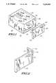
- FIG. 1is an exploded view of a disassembled electronic device having a housing and a battery door in accordance with a preferred embodiment of the present invention.
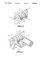
- FIG. 2is an illustration of the battery door of FIG. 1 in a closed position in accordance with the preferred embodiment of the present invention.
- FIG. 3is an isometric view of the inside of the battery door of FIG. 1 coupled to an electrical contact in accordance with the preferred embodiment of the present invention.
- FIG. 4is an illustration depicting the employment of the electrical contact to transfer power from a battery to an electronic circuit in accordance with the preferred embodiment of the present invention.
- FIG. 1depicts an exploded view of a disassembled electronic device 100, such as a selective call receiver, in accordance with a preferred embodiment of the present invention.
- the electronic device 100preferably comprises a housing 105, wherein an electronic circuit 107 and a battery 108 are situated, and a battery door 110 for providing access to the battery 108.
- the battery door 110includes two extrusions 115, which are inserted into mounting cavities 120 formed into the housing 105, thereby hingeably mounting the battery door 110 to the housing 105.
- a slot 122is further formed into the battery door 110 such that a portion of a conductive element, i.e., an electrical contact 125, which is coupled to the battery door 110, extends through the slot 122.
- the battery door 110When mounted to the housing 105, the battery door 110 may be pivotally rotated between an open position, in which the battery 108 may be accessed, and a closed position, as shown in FIG. 2.
- the electrical contact 125encounters a ramped surface 128 formed into the housing 105.
- the electrical contact 125which is preferably formed from a resilient material, forcibly slides along the ramped surface 128, causing the displacement of the electrical contact 125 within the slot 122.
- the electrical contact 125formed, as described above, from a resilient material, springs back into place, thus engaging a locking cavity 130 formed into the housing 105.
- the engagement of the locking cavity 130thereby secures the battery door 110 in the closed position.
- the battery door 110may be thereafter rotated into the open position when the electrical contact 125 is forcibly displaced within the slot 122 such that it disengages the locking cavity 130.
- Such displacement of the electrical contact 125results when force is exerted against the portion of the electrical contact 125 extending through the slot 122.
- FIG. 3an isometric view of the inside of the battery door 110 is depicted.
- the electrical contact 125which is employed to engage the locking cavity 130 (FIG. 1), is mounted to the battery door 110 by a clasp 305 formed into the battery door 110.
- an existing elementi.e., the electrical contact 125, is used to lock the battery door 110 in the closed position. Therefore, this integrated locking mechanism eliminates many of the problems, such as stocking and assembly, associated with the use of additional parts.
- the electrical contact 125transfers power from the battery 108 to the electronic circuit 107 when the electrical contact 125 engages the locking cavity 130, i.e., when the battery door 110 is secured in the closed position.
- a coiled end 405 of the electrical contact 125is forced into contact with the battery 108 when the battery door 110 is closed.
- the electrical contact 125electrically couples to the electronic circuit 107, preferably by means of a conductive element 410 mounted to the electronic circuit 107. In this manner, the battery 108 is able to power the electronic circuit 107 without the use of circuitry additional to that provided by the battery door 110.
- the battery door 110is opened and closed with a pivotal, rather than sliding, movement, the electrical contact 125 mounted to the battery door 110 is not worn as a result of repeatedly accessing the battery 108. Therefore, sufficient electrical coupling between the battery 108 and the electronic circuit 107 is ensured.
- the electrical contact 125is described as coupling the battery 108 to one electronic circuit 107, it may be appreciated that any number of electronic circuits could be powered, via the electrical contact 125, by the battery 108. Furthermore, the electrical contact 125 could, in alternate embodiments of the present invention, be employed to couple electrically equivalent areas, e.g., ground planes, of several electronic circuits to each other, rather than to a battery.
- a hinged battery door having an integrated locking mechanismeliminates some of the problems associated with the use of conventional battery doors.
- the pivotal operation of the battery doorprovides for repeated use of the battery door, such as during replacement of the battery, without the wear on an electrical contact which would occur during use of a conventional sliding the battery door.
- the hinged battery doorremains mounted to the housing when in an open position, thus preventing the loss of the battery door.
- a further feature of the present inventionis the employment of the existing electrical contact as a locking mechanism. Therefore, unlike conventional hinged battery doors, additional parts for locking the battery door into a closed position are not necessary. As a result, possible manufacturing problems, such as those created during stocking and assembling an additional part, are avoided.
Landscapes
- Chemical & Material Sciences (AREA)
- Chemical Kinetics & Catalysis (AREA)
- Electrochemistry (AREA)
- General Chemical & Material Sciences (AREA)
- Battery Mounting, Suspending (AREA)
Abstract
Description
This invention relates in general to an improved battery door, and more specifically to a battery door having an integrated locking mechanism.
Battery doors are typically used to provide access to batteries which power electronic devices. In small personal electronic devices, e.g., selective call receivers, a battery door may be opened to allow access to a battery which is situated within the housing of the selective call receiver. The battery may thereafter be removed and replaced when necessary.
The typically small size of selective call receivers commonly results in battery doors which slide open to permit access to the battery. This type of conventional battery door often includes conductive elements, such as electrical contacts, for transferring the power stored in the battery to one or more electronic circuits contained within the housing of the selective call receiver. When the battery door is in a closed position, the electrical contacts typically couple the electronic circuits to the battery, thereby conveniently providing for the flow of power from the battery. This type of door, however, must often be detachable to permit full accessibility to the battery. As a result, the battery door is frequently misplaced or lost. Furthermore, the sliding motion used to engage and disengage the battery door often results in wear to the electrical contacts due to the friction produced between the battery and the electrical contacts. After frequent replacement of the battery, therefore, the electrical contacts could become worn to such a degree that they provide insufficient or only sporadic electrical coupling between the electronic circuits and the battery.
An alternative to this type of sliding battery door is a hinged battery door that rotates between the open position, wherein the battery is accessible, and the closed position, wherein the electrical contacts couple the battery to the electronic circuits contained within the housing of the selective call receiver. Although wear on the electrical contacts is avoided through use of a hinged battery door, this type of battery door typically includes a transverse or rotating locking member to ensure that the battery door remains closed during normal operation of the selective call receiver. The locking member is commonly designed as an additional part that is moveably mounted to the battery door. Therefore, the locking member must be ordered, stocked, and assembled separately from other parts included in the selective call receiver, resulting in possible manufacturing problems, such as loss of the locking member or improper assembly of the locking member.
Thus, what is needed is a battery door having an integrated locking mechanism. Additionally, the operation of the battery door should prevent wear on electrical contacts due to friction.
A housing assembly for enclosing a battery and electrical circuitry comprises a housing element formed to enclose the battery and the electrical circuitry and a battery door for providing access to the battery enclosed by the housing element, wherein the battery door comprises mounting means for pivotally mounting the battery door to the housing element such that the battery door rotates between an open and a closed position. The housing assembly further comprises a conductive element mounted to the battery door for engaging the housing element to secure the battery door in the closed position, wherein the conductive element electrically contacts the battery and the electrical circuitry to provide battery power to the electrical circuitry when the battery door is in the closed position.
FIG. 1 is an exploded view of a disassembled electronic device having a housing and a battery door in accordance with a preferred embodiment of the present invention.
FIG. 2 is an illustration of the battery door of FIG. 1 in a closed position in accordance with the preferred embodiment of the present invention.
FIG. 3 is an isometric view of the inside of the battery door of FIG. 1 coupled to an electrical contact in accordance with the preferred embodiment of the present invention.
FIG. 4 is an illustration depicting the employment of the electrical contact to transfer power from a battery to an electronic circuit in accordance with the preferred embodiment of the present invention.
FIG. 1 depicts an exploded view of a disassembledelectronic device 100, such as a selective call receiver, in accordance with a preferred embodiment of the present invention. Theelectronic device 100 preferably comprises ahousing 105, wherein anelectronic circuit 107 and abattery 108 are situated, and abattery door 110 for providing access to thebattery 108. Thebattery door 110 includes twoextrusions 115, which are inserted intomounting cavities 120 formed into thehousing 105, thereby hingeably mounting thebattery door 110 to thehousing 105. Aslot 122 is further formed into thebattery door 110 such that a portion of a conductive element, i.e., anelectrical contact 125, which is coupled to thebattery door 110, extends through theslot 122.
When mounted to thehousing 105, thebattery door 110 may be pivotally rotated between an open position, in which thebattery 108 may be accessed, and a closed position, as shown in FIG. 2. According to the present invention, when thebattery door 110 is rotated into the closed position, theelectrical contact 125 encounters a rampedsurface 128 formed into thehousing 105. As thebattery door 110 continues to be rotated into the closed position, theelectrical contact 125, which is preferably formed from a resilient material, forcibly slides along the rampedsurface 128, causing the displacement of theelectrical contact 125 within theslot 122.
Returning to FIG. 1, when thebattery door 110 is completely closed, theelectrical contact 125, formed, as described above, from a resilient material, springs back into place, thus engaging alocking cavity 130 formed into thehousing 105. The engagement of thelocking cavity 130 thereby secures thebattery door 110 in the closed position. Preferably, thebattery door 110 may be thereafter rotated into the open position when theelectrical contact 125 is forcibly displaced within theslot 122 such that it disengages thelocking cavity 130. Such displacement of theelectrical contact 125 results when force is exerted against the portion of theelectrical contact 125 extending through theslot 122. Referring next to FIG. 3, an isometric view of the inside of thebattery door 110 is depicted. In accordance with the preferred embodiment of the present invention, theelectrical contact 125, which is employed to engage the locking cavity 130 (FIG. 1), is mounted to thebattery door 110 by aclasp 305 formed into thebattery door 110. In this manner, unlike conventional battery doors, an existing element, i.e., theelectrical contact 125, is used to lock thebattery door 110 in the closed position. Therefore, this integrated locking mechanism eliminates many of the problems, such as stocking and assembly, associated with the use of additional parts.
With reference to FIG. 4, theelectrical contact 125 transfers power from thebattery 108 to theelectronic circuit 107 when theelectrical contact 125 engages thelocking cavity 130, i.e., when thebattery door 110 is secured in the closed position. In accordance with the preferred embodiment of the present invention, acoiled end 405 of theelectrical contact 125 is forced into contact with thebattery 108 when thebattery door 110 is closed. At the same time, theelectrical contact 125 electrically couples to theelectronic circuit 107, preferably by means of aconductive element 410 mounted to theelectronic circuit 107. In this manner, thebattery 108 is able to power theelectronic circuit 107 without the use of circuitry additional to that provided by thebattery door 110. Also, because thebattery door 110 is opened and closed with a pivotal, rather than sliding, movement, theelectrical contact 125 mounted to thebattery door 110 is not worn as a result of repeatedly accessing thebattery 108. Therefore, sufficient electrical coupling between thebattery 108 and theelectronic circuit 107 is ensured.
Although, in accordance with the preferred embodiment of the present invention, theelectrical contact 125 is described as coupling thebattery 108 to oneelectronic circuit 107, it may be appreciated that any number of electronic circuits could be powered, via theelectrical contact 125, by thebattery 108. Furthermore, theelectrical contact 125 could, in alternate embodiments of the present invention, be employed to couple electrically equivalent areas, e.g., ground planes, of several electronic circuits to each other, rather than to a battery.
In summary, a hinged battery door having an integrated locking mechanism, in accordance with the preferred embodiment of the present invention, eliminates some of the problems associated with the use of conventional battery doors. As described above, the pivotal operation of the battery door provides for repeated use of the battery door, such as during replacement of the battery, without the wear on an electrical contact which would occur during use of a conventional sliding the battery door. Furthermore, the hinged battery door remains mounted to the housing when in an open position, thus preventing the loss of the battery door.
A further feature of the present invention is the employment of the existing electrical contact as a locking mechanism. Therefore, unlike conventional hinged battery doors, additional parts for locking the battery door into a closed position are not necessary. As a result, possible manufacturing problems, such as those created during stocking and assembling an additional part, are avoided.
By now, it may be appreciated that there has been provided a battery door having an integrated locking mechanism, the operation of which does not cause wear on an electrical contact mounted to the battery door.
Claims (8)
1. A housing assembly for enclosing a battery and electrical circuitry, comprising:
a housing element formed to enclose the battery and the electrical circuitry;
a battery door for providing access to the battery enclosed by the housing element, wherein the battery door comprises mounting means for pivotally mounting the battery door to the housing element such that the battery door rotates between an open and a closed position; and
a conductive element mounted to the battery door for engaging the housing element to secure the battery door in the closed position, wherein the conductive element electrically contacts the battery and the electrical circuitry to provide battery power to the electrical circuitry when the battery door is in the closed position.
2. The housing assembly in accordance with the claim 1, wherein:
the battery door has a slot formed therein; and
a portion of the conductive element extends through the slot in the battery door such that, when the battery door is secured in the closed position by the conductive element, the portion of the conductive element is manipulated to disengage the conductive element from the housing element, thereby unlocking the battery door from the closed position.
3. The housing assembly in accordance with claim 1, wherein:
the housing element has mounting cavities formed therein; and
the mounting means includes mounting extrusions formed into the battery door, wherein the mounting extrusions are inserted into the mounting cavities formed into the housing element to hingeably mount the battery door to the housing element.
4. An electronic device, comprising:
electronic circuitry capable of being powered by a battery;
a housing for enclosing the electronic circuitry and the battery;
a battery door for providing access to the battery, the battery door comprising mounting means for pivotally mounting the battery door to the housing such that the battery door rotates between an open and a closed position; and
a conductive element mounted to the battery door for engaging the housing to secure the battery door in the closed position, wherein the conductive element contacts the battery and the electronic circuitry when the battery door is in the closed position, thereby electrically coupling the battery to the electronic circuitry.
5. The electronic device in accordance with claim 4, wherein:
the battery door has a slot formed therein; and
a portion of the conductive element extends through the slot in the battery door such that, when the battery door is secured in the closed position by the conductive element, the portion of the conductive element is manipulated to disengage the conductive element from the housing, thereby unlocking the battery door from the closed position.
6. The electronic device in accordance with claim 4, wherein:
the housing has mounting cavities formed therein; and
the mounting means includes mounting extrusions formed into the battery door, wherein the mounting extrusions are inserted into the mounting cavities formed into the housing to hingeably mount the battery door to the housing.
7. A selective call receiver, comprising:
receiver means for receiving a message, and capable of being powered by a battery;
a housing for enclosing the receiver means and the battery;
a battery door for providing access to the battery,
the battery door comprises mounting means for pivotally mounting the battery door to the housing such that the battery door rotates between an open and a closed position; and
the battery door has a slot formed therein; and
a conductive element is mounted to the battery door for engaging the housing to secure the battery door in the closed position, wherein:
the conductive element further contacts the battery and the receiver means, thereby electrically coupling the battery to the receiver means; and
a portion of the conductive element extends through the slot in the battery door such that, when the battery door is secured in the closed position by the conductive element, the portion of the conductive element is manipulated to disengage the conductive element from the housing, thereby unlocking the battery door from the closed position.
8. The selective call receiver in accordance with claim 7, wherein:
the housing has mounting cavities formed therein; and
the mounting means includes mounting extrusions formed into the battery door wherein the mounting extrusions are inserted into the mounting cavities formed into the housing to hingeably mount the battery door to the housing.
Priority Applications (1)
| Application Number | Priority Date | Filing Date | Title |
|---|---|---|---|
| US07/921,664US5248569A (en) | 1992-07-30 | 1992-07-30 | Battery door having integrated locking mechanism |
Applications Claiming Priority (1)
| Application Number | Priority Date | Filing Date | Title |
|---|---|---|---|
| US07/921,664US5248569A (en) | 1992-07-30 | 1992-07-30 | Battery door having integrated locking mechanism |
Publications (1)
| Publication Number | Publication Date |
|---|---|
| US5248569Atrue US5248569A (en) | 1993-09-28 |
Family
ID=25445778
Family Applications (1)
| Application Number | Title | Priority Date | Filing Date |
|---|---|---|---|
| US07/921,664Expired - Fee RelatedUS5248569A (en) | 1992-07-30 | 1992-07-30 | Battery door having integrated locking mechanism |
Country Status (1)
| Country | Link |
|---|---|
| US (1) | US5248569A (en) |
Cited By (48)
| Publication number | Priority date | Publication date | Assignee | Title |
|---|---|---|---|---|
| US5508124A (en)* | 1994-08-23 | 1996-04-16 | Motorola, Inc. | Confined battery door |
| US5716730A (en)* | 1995-06-30 | 1998-02-10 | Nec Corporation | Battery case mounting structure for electronic equipment |
| US5826176A (en)* | 1995-10-19 | 1998-10-20 | Daewoo Electronics Co., Ltd. | Slidable card receptor for use in a satellite broadcasting tuner |
| US5833491A (en)* | 1995-04-21 | 1998-11-10 | Sony Corporation | Electronic equipment having a miniaturized cell container having a securely locked cover with switch |
| US5844401A (en)* | 1996-05-16 | 1998-12-01 | Samsung Electronics Co., Ltd. | Charging device for easy mounting/dismounting of a battery |
| WO1999046466A1 (en)* | 1998-03-09 | 1999-09-16 | Schneider Automation, Inc. | Battery door assembly |
| US6463221B2 (en)* | 2000-01-17 | 2002-10-08 | Funai Electric, Co., Ltd. | Battery accommodating device |
| US20050115067A1 (en)* | 2001-10-26 | 2005-06-02 | Luzzi Glenn J. | Adapter mandrel used in conjunction with premolded high voltage connectors and connector components |
| US20080012527A1 (en)* | 2001-11-09 | 2008-01-17 | Zick Jonathan A | Electrical component, such as a radio, mp3 player, audio component, battery charger, radio/charger, mp3 player/radio, mp3 player/charger or mp3 player/radio/charger, having a selectively connectable battery charger |
| US20080225519A1 (en)* | 2003-08-08 | 2008-09-18 | Uke Alan K | Flashlight with drop-in side-by-side batteries |
| US7471063B2 (en) | 2001-11-09 | 2008-12-30 | Milwaukee Electric Tool Corporation | Electrical combination, electrical component and battery charger |
| US20090296324A1 (en)* | 2008-05-30 | 2009-12-03 | Shenzhen Futaihong Precision Industry Co., Ltd. | Cover latching mechanism for electronic device |
| EP2144456A1 (en)* | 2008-07-10 | 2010-01-13 | Siemens Medical Instruments Pte. Ltd. | Hearing aid with lockable battery chamber |
| US20110069428A1 (en)* | 2009-09-22 | 2011-03-24 | Shenzhen Futaihong Precision Industry Co., Ltd. | Cover mechanism and electronic device using same |
| US8016789B2 (en) | 2008-10-10 | 2011-09-13 | Deka Products Limited Partnership | Pump assembly with a removable cover assembly |
| US8034026B2 (en) | 2001-05-18 | 2011-10-11 | Deka Products Limited Partnership | Infusion pump assembly |
| US8066672B2 (en) | 2008-10-10 | 2011-11-29 | Deka Products Limited Partnership | Infusion pump assembly with a backup power supply |
| US8113244B2 (en) | 2006-02-09 | 2012-02-14 | Deka Products Limited Partnership | Adhesive and peripheral systems and methods for medical devices |
| US8223028B2 (en) | 2008-10-10 | 2012-07-17 | Deka Products Limited Partnership | Occlusion detection system and method |
| US8262616B2 (en) | 2008-10-10 | 2012-09-11 | Deka Products Limited Partnership | Infusion pump assembly |
| US8267892B2 (en) | 2008-10-10 | 2012-09-18 | Deka Products Limited Partnership | Multi-language / multi-processor infusion pump assembly |
| US8414563B2 (en) | 2007-12-31 | 2013-04-09 | Deka Products Limited Partnership | Pump assembly with switch |
| US8496646B2 (en) | 2007-02-09 | 2013-07-30 | Deka Products Limited Partnership | Infusion pump assembly |
| US20130285524A1 (en)* | 2012-04-26 | 2013-10-31 | Fih (Hong Kong) Limited | Housing with integral protective cover and volume key |
| US8708376B2 (en) | 2008-10-10 | 2014-04-29 | Deka Products Limited Partnership | Medium connector |
| US9173996B2 (en) | 2001-05-18 | 2015-11-03 | Deka Products Limited Partnership | Infusion set for a fluid pump |
| US9180245B2 (en) | 2008-10-10 | 2015-11-10 | Deka Products Limited Partnership | System and method for administering an infusible fluid |
| US11364335B2 (en) | 2006-02-09 | 2022-06-21 | Deka Products Limited Partnership | Apparatus, system and method for fluid delivery |
| US11395877B2 (en) | 2006-02-09 | 2022-07-26 | Deka Products Limited Partnership | Systems and methods for fluid delivery |
| US11404776B2 (en) | 2007-12-31 | 2022-08-02 | Deka Products Limited Partnership | Split ring resonator antenna adapted for use in wirelessly controlled medical device |
| US11426512B2 (en) | 2006-02-09 | 2022-08-30 | Deka Products Limited Partnership | Apparatus, systems and methods for an infusion pump assembly |
| US11478623B2 (en) | 2006-02-09 | 2022-10-25 | Deka Products Limited Partnership | Infusion pump assembly |
| US11497846B2 (en) | 2006-02-09 | 2022-11-15 | Deka Products Limited Partnership | Patch-sized fluid delivery systems and methods |
| US11497686B2 (en) | 2007-12-31 | 2022-11-15 | Deka Products Limited Partnership | Apparatus, system and method for fluid delivery |
| US11524151B2 (en) | 2012-03-07 | 2022-12-13 | Deka Products Limited Partnership | Apparatus, system and method for fluid delivery |
| US11523972B2 (en) | 2018-04-24 | 2022-12-13 | Deka Products Limited Partnership | Apparatus, system and method for fluid delivery |
| US11534542B2 (en) | 2007-12-31 | 2022-12-27 | Deka Products Limited Partnership | Apparatus, system and method for fluid delivery |
| US11597541B2 (en) | 2013-07-03 | 2023-03-07 | Deka Products Limited Partnership | Apparatus, system and method for fluid delivery |
| US11642283B2 (en) | 2007-12-31 | 2023-05-09 | Deka Products Limited Partnership | Method for fluid delivery |
| US11723841B2 (en) | 2007-12-31 | 2023-08-15 | Deka Products Limited Partnership | Apparatus, system and method for fluid delivery |
| US11890448B2 (en) | 2006-02-09 | 2024-02-06 | Deka Products Limited Partnership | Method and system for shape-memory alloy wire control |
| US11964126B2 (en) | 2006-02-09 | 2024-04-23 | Deka Products Limited Partnership | Infusion pump assembly |
| US12064590B2 (en) | 2006-02-09 | 2024-08-20 | Deka Products Limited Partnership | Patch-sized fluid delivery systems and methods |
| US12070574B2 (en) | 2006-02-09 | 2024-08-27 | Deka Products Limited Partnership | Apparatus, systems and methods for an infusion pump assembly |
| US12151080B2 (en) | 2006-02-09 | 2024-11-26 | Deka Products Limited Partnership | Adhesive and peripheral systems and methods for medical devices |
| US12186531B2 (en) | 2008-10-10 | 2025-01-07 | Deka Products Limited Partnership | Infusion pump assembly |
| US12274857B2 (en) | 2006-02-09 | 2025-04-15 | Deka Products Limited Partnership | Method and system for shape-memory alloy wire control |
| US12370327B2 (en) | 2008-10-10 | 2025-07-29 | Deka Products Limited Partnership | Infusion pump methods, systems and apparatus |
Citations (11)
| Publication number | Priority date | Publication date | Assignee | Title |
|---|---|---|---|---|
| US3693089A (en)* | 1971-05-20 | 1972-09-19 | Motorola Inc | Housing assembly for miniature radio apparatus with self contained battery |
| US3881961A (en)* | 1973-08-02 | 1975-05-06 | Motorola Inc | Battery housing |
| US4129688A (en)* | 1977-02-18 | 1978-12-12 | U.S. Philips Corporation | Battery compartment in portable apparatus |
| US4230777A (en)* | 1979-04-02 | 1980-10-28 | Motorola, Inc. | Battery holder with integral access door and power switch |
| US4371594A (en)* | 1980-10-03 | 1983-02-01 | Canon Kabushiki Kaisha | Battery accommodating device |
| US4391883A (en)* | 1981-09-28 | 1983-07-05 | Motorola, Inc. | Housing arrangement with breakaway battery access door |
| US4690878A (en)* | 1985-08-23 | 1987-09-01 | Minolta Camera Kabukishi Kaisha | Battery power detector for sensing presence of batteries |
| US4880712A (en)* | 1989-03-08 | 1989-11-14 | Motorola, Inc. | Battery housing |
| US4965141A (en)* | 1988-11-07 | 1990-10-23 | Nikon Corporation | Electric cell housing device for camera |
| US4972508A (en)* | 1989-08-28 | 1990-11-20 | Motorola, Inc. | Housing for a battery powered device |
| US4993973A (en)* | 1989-11-20 | 1991-02-19 | Motorola, Inc. | Battery contact |
- 1992
- 1992-07-30USUS07/921,664patent/US5248569A/ennot_activeExpired - Fee Related
Patent Citations (11)
| Publication number | Priority date | Publication date | Assignee | Title |
|---|---|---|---|---|
| US3693089A (en)* | 1971-05-20 | 1972-09-19 | Motorola Inc | Housing assembly for miniature radio apparatus with self contained battery |
| US3881961A (en)* | 1973-08-02 | 1975-05-06 | Motorola Inc | Battery housing |
| US4129688A (en)* | 1977-02-18 | 1978-12-12 | U.S. Philips Corporation | Battery compartment in portable apparatus |
| US4230777A (en)* | 1979-04-02 | 1980-10-28 | Motorola, Inc. | Battery holder with integral access door and power switch |
| US4371594A (en)* | 1980-10-03 | 1983-02-01 | Canon Kabushiki Kaisha | Battery accommodating device |
| US4391883A (en)* | 1981-09-28 | 1983-07-05 | Motorola, Inc. | Housing arrangement with breakaway battery access door |
| US4690878A (en)* | 1985-08-23 | 1987-09-01 | Minolta Camera Kabukishi Kaisha | Battery power detector for sensing presence of batteries |
| US4965141A (en)* | 1988-11-07 | 1990-10-23 | Nikon Corporation | Electric cell housing device for camera |
| US4880712A (en)* | 1989-03-08 | 1989-11-14 | Motorola, Inc. | Battery housing |
| US4972508A (en)* | 1989-08-28 | 1990-11-20 | Motorola, Inc. | Housing for a battery powered device |
| US4993973A (en)* | 1989-11-20 | 1991-02-19 | Motorola, Inc. | Battery contact |
Cited By (84)
| Publication number | Priority date | Publication date | Assignee | Title |
|---|---|---|---|---|
| US5508124A (en)* | 1994-08-23 | 1996-04-16 | Motorola, Inc. | Confined battery door |
| US5833491A (en)* | 1995-04-21 | 1998-11-10 | Sony Corporation | Electronic equipment having a miniaturized cell container having a securely locked cover with switch |
| US5716730A (en)* | 1995-06-30 | 1998-02-10 | Nec Corporation | Battery case mounting structure for electronic equipment |
| US5826176A (en)* | 1995-10-19 | 1998-10-20 | Daewoo Electronics Co., Ltd. | Slidable card receptor for use in a satellite broadcasting tuner |
| US5844401A (en)* | 1996-05-16 | 1998-12-01 | Samsung Electronics Co., Ltd. | Charging device for easy mounting/dismounting of a battery |
| WO1999046466A1 (en)* | 1998-03-09 | 1999-09-16 | Schneider Automation, Inc. | Battery door assembly |
| US6463221B2 (en)* | 2000-01-17 | 2002-10-08 | Funai Electric, Co., Ltd. | Battery accommodating device |
| US8034026B2 (en) | 2001-05-18 | 2011-10-11 | Deka Products Limited Partnership | Infusion pump assembly |
| US9173996B2 (en) | 2001-05-18 | 2015-11-03 | Deka Products Limited Partnership | Infusion set for a fluid pump |
| US20050115067A1 (en)* | 2001-10-26 | 2005-06-02 | Luzzi Glenn J. | Adapter mandrel used in conjunction with premolded high voltage connectors and connector components |
| US20080012527A1 (en)* | 2001-11-09 | 2008-01-17 | Zick Jonathan A | Electrical component, such as a radio, mp3 player, audio component, battery charger, radio/charger, mp3 player/radio, mp3 player/charger or mp3 player/radio/charger, having a selectively connectable battery charger |
| US7557537B2 (en) | 2001-11-09 | 2009-07-07 | Milwaukee Electric Tool Corporation | Electrical component having a selectively connectable battery charger |
| US7609027B2 (en) | 2001-11-09 | 2009-10-27 | Milwaukee Electric Tool Corporation | Electrical component, audio component, or electrical combination having a selectively connectable battery charger |
| US7471063B2 (en) | 2001-11-09 | 2008-12-30 | Milwaukee Electric Tool Corporation | Electrical combination, electrical component and battery charger |
| US7868590B2 (en) | 2001-11-09 | 2011-01-11 | Milwaukee Electric Tool Corporation | Electrical component, such as a radio, MP3 player, audio component, battery charger, radio/charger, MP3 player/radio, MP3 player/charger or MP3 player/radio/charger, having a selectively connectable battery charger |
| US8203307B2 (en) | 2001-11-09 | 2012-06-19 | Milwaukee Electric Tool Corporation | Audio and charging system with audio device, power tool battery, and external battery charger |
| US20080225519A1 (en)* | 2003-08-08 | 2008-09-18 | Uke Alan K | Flashlight with drop-in side-by-side batteries |
| US11408414B2 (en) | 2006-02-09 | 2022-08-09 | Deka Products Limited Partnership | Adhesive and peripheral systems and methods for medical devices |
| US11712513B2 (en) | 2006-02-09 | 2023-08-01 | Deka Products Limited Partnership | Adhesive and peripheral systems and methods for medical devices |
| US11890448B2 (en) | 2006-02-09 | 2024-02-06 | Deka Products Limited Partnership | Method and system for shape-memory alloy wire control |
| US8113244B2 (en) | 2006-02-09 | 2012-02-14 | Deka Products Limited Partnership | Adhesive and peripheral systems and methods for medical devices |
| US12311143B2 (en) | 2006-02-09 | 2025-05-27 | Deka Products Limited Partnership | Adhesive and peripheral systems and methods for medical devices |
| US12274857B2 (en) | 2006-02-09 | 2025-04-15 | Deka Products Limited Partnership | Method and system for shape-memory alloy wire control |
| US12233236B2 (en) | 2006-02-09 | 2025-02-25 | Deka Products Limited Partnership | Adhesive and peripheral systems and methods for medical devices |
| US12151080B2 (en) | 2006-02-09 | 2024-11-26 | Deka Products Limited Partnership | Adhesive and peripheral systems and methods for medical devices |
| US11844926B2 (en) | 2006-02-09 | 2023-12-19 | Deka Products Limited Partnership | Adhesive and peripheral systems and methods for medical devices |
| US8414522B2 (en) | 2006-02-09 | 2013-04-09 | Deka Products Limited Partnership | Fluid delivery systems and methods |
| US11786651B2 (en) | 2006-02-09 | 2023-10-17 | Deka Products Limited Partnership | Patch-sized fluid delivery system |
| US11738139B2 (en) | 2006-02-09 | 2023-08-29 | Deka Products Limited Partnership | Patch-sized fluid delivery systems and methods |
| US11904134B2 (en) | 2006-02-09 | 2024-02-20 | Deka Products Limited Partnership | Patch-sized fluid delivery systems and methods |
| US8545445B2 (en) | 2006-02-09 | 2013-10-01 | Deka Products Limited Partnership | Patch-sized fluid delivery systems and methods |
| US11717609B2 (en) | 2006-02-09 | 2023-08-08 | Deka Products Limited Partnership | Adhesive and peripheral systems and methods for medical devices |
| US8585377B2 (en) | 2006-02-09 | 2013-11-19 | Deka Products Limited Partnership | Pumping fluid delivery systems and methods using force application assembly |
| US12070574B2 (en) | 2006-02-09 | 2024-08-27 | Deka Products Limited Partnership | Apparatus, systems and methods for an infusion pump assembly |
| US11534543B2 (en) | 2006-02-09 | 2022-12-27 | Deka Products Limited Partnership | Method for making patch-sized fluid delivery systems |
| US12064590B2 (en) | 2006-02-09 | 2024-08-20 | Deka Products Limited Partnership | Patch-sized fluid delivery systems and methods |
| US11690952B2 (en) | 2006-02-09 | 2023-07-04 | Deka Products Limited Partnership | Pumping fluid delivery systems and methods using force application assembly |
| US11339774B2 (en) | 2006-02-09 | 2022-05-24 | Deka Products Limited Partnership | Adhesive and peripheral systems and methods for medical devices |
| US11364335B2 (en) | 2006-02-09 | 2022-06-21 | Deka Products Limited Partnership | Apparatus, system and method for fluid delivery |
| US11391273B2 (en) | 2006-02-09 | 2022-07-19 | Deka Products Limited Partnership | Adhesive and peripheral systems and methods for medical devices |
| US11395877B2 (en) | 2006-02-09 | 2022-07-26 | Deka Products Limited Partnership | Systems and methods for fluid delivery |
| US11617826B2 (en) | 2006-02-09 | 2023-04-04 | Deka Products Limited Partnership | Patch-sized fluid delivery systems and methods |
| US11406753B2 (en) | 2006-02-09 | 2022-08-09 | Deka Products Limited Partnership | Adhesive and peripheral systems and methods for medical devices |
| US11964126B2 (en) | 2006-02-09 | 2024-04-23 | Deka Products Limited Partnership | Infusion pump assembly |
| US11413391B2 (en) | 2006-02-09 | 2022-08-16 | Deka Products Limited Partnership | Patch-sized fluid delivery systems and methods |
| US11426512B2 (en) | 2006-02-09 | 2022-08-30 | Deka Products Limited Partnership | Apparatus, systems and methods for an infusion pump assembly |
| US11478623B2 (en) | 2006-02-09 | 2022-10-25 | Deka Products Limited Partnership | Infusion pump assembly |
| US11491273B2 (en) | 2006-02-09 | 2022-11-08 | Deka Products Limited Partnership | Adhesive and peripheral systems and methods for medical devices |
| US11497846B2 (en) | 2006-02-09 | 2022-11-15 | Deka Products Limited Partnership | Patch-sized fluid delivery systems and methods |
| US11559625B2 (en) | 2006-02-09 | 2023-01-24 | Deka Products Limited Partnership | Patch-sized fluid delivery systems and methods |
| US12036387B2 (en) | 2006-02-09 | 2024-07-16 | Deka Products Limited Partnership | Device to determine volume of fluid dispensed |
| US11992650B2 (en) | 2006-02-09 | 2024-05-28 | Deka Products Limited Partnership | Adhesive and peripheral systems and methods for medical devices |
| US8496646B2 (en) | 2007-02-09 | 2013-07-30 | Deka Products Limited Partnership | Infusion pump assembly |
| US11701300B2 (en) | 2007-12-31 | 2023-07-18 | Deka Products Limited Partnership | Method for fluid delivery |
| US8491570B2 (en) | 2007-12-31 | 2013-07-23 | Deka Products Limited Partnership | Infusion pump assembly |
| US11894609B2 (en) | 2007-12-31 | 2024-02-06 | Deka Products Limited Partnership | Split ring resonator antenna adapted for use in wirelessly controlled medical device |
| US11404776B2 (en) | 2007-12-31 | 2022-08-02 | Deka Products Limited Partnership | Split ring resonator antenna adapted for use in wirelessly controlled medical device |
| US11642283B2 (en) | 2007-12-31 | 2023-05-09 | Deka Products Limited Partnership | Method for fluid delivery |
| US9526830B2 (en) | 2007-12-31 | 2016-12-27 | Deka Products Limited Partnership | Wearable pump assembly |
| US11497686B2 (en) | 2007-12-31 | 2022-11-15 | Deka Products Limited Partnership | Apparatus, system and method for fluid delivery |
| US12121497B2 (en) | 2007-12-31 | 2024-10-22 | Deka Products Limited Partnership | Method for fluid delivery |
| US11534542B2 (en) | 2007-12-31 | 2022-12-27 | Deka Products Limited Partnership | Apparatus, system and method for fluid delivery |
| US11723841B2 (en) | 2007-12-31 | 2023-08-15 | Deka Products Limited Partnership | Apparatus, system and method for fluid delivery |
| US12415031B2 (en) | 2007-12-31 | 2025-09-16 | Deka Products Limited Partnership | Wearable pump assembly |
| US8414563B2 (en) | 2007-12-31 | 2013-04-09 | Deka Products Limited Partnership | Pump assembly with switch |
| US12128006B2 (en) | 2007-12-31 | 2024-10-29 | Deka Products Limited Partnership | Apparatus, system and method for fluid delivery |
| US20090296324A1 (en)* | 2008-05-30 | 2009-12-03 | Shenzhen Futaihong Precision Industry Co., Ltd. | Cover latching mechanism for electronic device |
| EP2144456A1 (en)* | 2008-07-10 | 2010-01-13 | Siemens Medical Instruments Pte. Ltd. | Hearing aid with lockable battery chamber |
| US8708376B2 (en) | 2008-10-10 | 2014-04-29 | Deka Products Limited Partnership | Medium connector |
| US8223028B2 (en) | 2008-10-10 | 2012-07-17 | Deka Products Limited Partnership | Occlusion detection system and method |
| US8066672B2 (en) | 2008-10-10 | 2011-11-29 | Deka Products Limited Partnership | Infusion pump assembly with a backup power supply |
| US12370327B2 (en) | 2008-10-10 | 2025-07-29 | Deka Products Limited Partnership | Infusion pump methods, systems and apparatus |
| US9180245B2 (en) | 2008-10-10 | 2015-11-10 | Deka Products Limited Partnership | System and method for administering an infusible fluid |
| US8016789B2 (en) | 2008-10-10 | 2011-09-13 | Deka Products Limited Partnership | Pump assembly with a removable cover assembly |
| US8267892B2 (en) | 2008-10-10 | 2012-09-18 | Deka Products Limited Partnership | Multi-language / multi-processor infusion pump assembly |
| US8262616B2 (en) | 2008-10-10 | 2012-09-11 | Deka Products Limited Partnership | Infusion pump assembly |
| US12186531B2 (en) | 2008-10-10 | 2025-01-07 | Deka Products Limited Partnership | Infusion pump assembly |
| US8164921B2 (en)* | 2009-09-22 | 2012-04-24 | Shenzhen Futaihong Precision Industry Co., Ltd. | Cover mechanism and electronic device using same |
| US20110069428A1 (en)* | 2009-09-22 | 2011-03-24 | Shenzhen Futaihong Precision Industry Co., Ltd. | Cover mechanism and electronic device using same |
| US11524151B2 (en) | 2012-03-07 | 2022-12-13 | Deka Products Limited Partnership | Apparatus, system and method for fluid delivery |
| US20130285524A1 (en)* | 2012-04-26 | 2013-10-31 | Fih (Hong Kong) Limited | Housing with integral protective cover and volume key |
| US11597541B2 (en) | 2013-07-03 | 2023-03-07 | Deka Products Limited Partnership | Apparatus, system and method for fluid delivery |
| US12012241B2 (en) | 2013-07-03 | 2024-06-18 | Deka Products Limited Partnership | Apparatus, system and method for fluid delivery |
| US11523972B2 (en) | 2018-04-24 | 2022-12-13 | Deka Products Limited Partnership | Apparatus, system and method for fluid delivery |
Similar Documents
| Publication | Publication Date | Title |
|---|---|---|
| US5248569A (en) | Battery door having integrated locking mechanism | |
| KR100621606B1 (en) | A portable computer | |
| JP3103157B2 (en) | Portable electronic devices | |
| US5390075A (en) | Electronic apparatus with flexible cable interconnect having independently movable member supported on tab portions | |
| US5270702A (en) | Battery door for a selective call receiver | |
| US6480390B2 (en) | Card-type peripheral device | |
| US5679013A (en) | Electrical connector and an electronic apparatus using the electrical connector | |
| US6120309A (en) | Electrical connector | |
| US4141616A (en) | Unitized connector arrangement for electrical apparatus | |
| US5586795A (en) | Embedded-type handle assembly | |
| US7714841B2 (en) | Wireless mouse | |
| US4984706A (en) | Hinged casing | |
| JPH0762417B2 (en) | Door latch device | |
| CN113489823A (en) | Electronic device | |
| US5339209A (en) | Plug-in actuator latch mechanism | |
| US5634815A (en) | Battery receiving mechanism | |
| US6203077B1 (en) | Over-center toggle latch with integral safety switch | |
| US6159632A (en) | Battery accommodating structure for electronic equipment | |
| US4993973A (en) | Battery contact | |
| US5212359A (en) | Multiple interface safety switch actuating mechanism | |
| US6068496A (en) | Sliding door for a dock port | |
| KR100659930B1 (en) | Electrical connector with shutter member | |
| GB2306052A (en) | Over centre toggle latch with integral switch | |
| US5005884A (en) | Cylinder lock modified for use with a card reader unlocking mechanism | |
| US3918750A (en) | Locking devices for doors |
Legal Events
| Date | Code | Title | Description |
|---|---|---|---|
| AS | Assignment | Owner name:MOTOROLA, INC., A CORP OF DE, ILLINOIS Free format text:ASSIGNMENT OF ASSIGNORS INTEREST.;ASSIGNORS:PINE, JERROLD S.;PEANA, STEFAN;HAHS, CHARLES A. JR.;REEL/FRAME:006229/0756 Effective date:19920727 | |
| CC | Certificate of correction | ||
| FPAY | Fee payment | Year of fee payment:4 | |
| FPAY | Fee payment | Year of fee payment:8 | |
| REMI | Maintenance fee reminder mailed | ||
| LAPS | Lapse for failure to pay maintenance fees | ||
| STCH | Information on status: patent discontinuation | Free format text:PATENT EXPIRED DUE TO NONPAYMENT OF MAINTENANCE FEES UNDER 37 CFR 1.362 | |
| FP | Expired due to failure to pay maintenance fee | Effective date:20050928 |