US5248275A - Balloon with flat film valve and method of manufacture - Google Patents
Balloon with flat film valve and method of manufactureDownload PDFInfo
- Publication number
- US5248275A US5248275AUS07/702,790US70279091AUS5248275AUS 5248275 AUS5248275 AUS 5248275AUS 70279091 AUS70279091 AUS 70279091AUS 5248275 AUS5248275 AUS 5248275A
- Authority
- US
- United States
- Prior art keywords
- valve
- neck
- balloon
- film strips
- portions
- Prior art date
- Legal status (The legal status is an assumption and is not a legal conclusion. Google has not performed a legal analysis and makes no representation as to the accuracy of the status listed.)
- Expired - Lifetime
Links
Images


Classifications
- A—HUMAN NECESSITIES
- A63—SPORTS; GAMES; AMUSEMENTS
- A63H—TOYS, e.g. TOPS, DOLLS, HOOPS OR BUILDING BLOCKS
- A63H27/00—Toy aircraft; Other flying toys
- A63H27/10—Balloons
- B—PERFORMING OPERATIONS; TRANSPORTING
- B29—WORKING OF PLASTICS; WORKING OF SUBSTANCES IN A PLASTIC STATE IN GENERAL
- B29C—SHAPING OR JOINING OF PLASTICS; SHAPING OF MATERIAL IN A PLASTIC STATE, NOT OTHERWISE PROVIDED FOR; AFTER-TREATMENT OF THE SHAPED PRODUCTS, e.g. REPAIRING
- B29C65/00—Joining or sealing of preformed parts, e.g. welding of plastics materials; Apparatus therefor
- B29C65/02—Joining or sealing of preformed parts, e.g. welding of plastics materials; Apparatus therefor by heating, with or without pressure
- B29C65/18—Joining or sealing of preformed parts, e.g. welding of plastics materials; Apparatus therefor by heating, with or without pressure using heated tools
- B—PERFORMING OPERATIONS; TRANSPORTING
- B29—WORKING OF PLASTICS; WORKING OF SUBSTANCES IN A PLASTIC STATE IN GENERAL
- B29C—SHAPING OR JOINING OF PLASTICS; SHAPING OF MATERIAL IN A PLASTIC STATE, NOT OTHERWISE PROVIDED FOR; AFTER-TREATMENT OF THE SHAPED PRODUCTS, e.g. REPAIRING
- B29C66/00—General aspects of processes or apparatus for joining preformed parts
- B29C66/004—Preventing sticking together, e.g. of some areas of the parts to be joined
- B—PERFORMING OPERATIONS; TRANSPORTING
- B29—WORKING OF PLASTICS; WORKING OF SUBSTANCES IN A PLASTIC STATE IN GENERAL
- B29C—SHAPING OR JOINING OF PLASTICS; SHAPING OF MATERIAL IN A PLASTIC STATE, NOT OTHERWISE PROVIDED FOR; AFTER-TREATMENT OF THE SHAPED PRODUCTS, e.g. REPAIRING
- B29C66/00—General aspects of processes or apparatus for joining preformed parts
- B29C66/01—General aspects dealing with the joint area or with the area to be joined
- B29C66/05—Particular design of joint configurations
- B29C66/10—Particular design of joint configurations particular design of the joint cross-sections
- B29C66/11—Joint cross-sections comprising a single joint-segment, i.e. one of the parts to be joined comprising a single joint-segment in the joint cross-section
- B29C66/112—Single lapped joints
- B29C66/1122—Single lap to lap joints, i.e. overlap joints
- B—PERFORMING OPERATIONS; TRANSPORTING
- B29—WORKING OF PLASTICS; WORKING OF SUBSTANCES IN A PLASTIC STATE IN GENERAL
- B29C—SHAPING OR JOINING OF PLASTICS; SHAPING OF MATERIAL IN A PLASTIC STATE, NOT OTHERWISE PROVIDED FOR; AFTER-TREATMENT OF THE SHAPED PRODUCTS, e.g. REPAIRING
- B29C66/00—General aspects of processes or apparatus for joining preformed parts
- B29C66/80—General aspects of machine operations or constructions and parts thereof
- B29C66/83—General aspects of machine operations or constructions and parts thereof characterised by the movement of the joining or pressing tools
- B29C66/832—Reciprocating joining or pressing tools
- B29C66/8322—Joining or pressing tools reciprocating along one axis
- B29C66/83221—Joining or pressing tools reciprocating along one axis cooperating reciprocating tools, each tool reciprocating along one axis
- F—MECHANICAL ENGINEERING; LIGHTING; HEATING; WEAPONS; BLASTING
- F16—ENGINEERING ELEMENTS AND UNITS; GENERAL MEASURES FOR PRODUCING AND MAINTAINING EFFECTIVE FUNCTIONING OF MACHINES OR INSTALLATIONS; THERMAL INSULATION IN GENERAL
- F16K—VALVES; TAPS; COCKS; ACTUATING-FLOATS; DEVICES FOR VENTING OR AERATING
- F16K15/00—Check valves
- F16K15/14—Check valves with flexible valve members
- F16K15/1402—Check valves with flexible valve members having an integral flexible member cooperating with a plurality of seating surfaces
- F—MECHANICAL ENGINEERING; LIGHTING; HEATING; WEAPONS; BLASTING
- F16—ENGINEERING ELEMENTS AND UNITS; GENERAL MEASURES FOR PRODUCING AND MAINTAINING EFFECTIVE FUNCTIONING OF MACHINES OR INSTALLATIONS; THERMAL INSULATION IN GENERAL
- F16K—VALVES; TAPS; COCKS; ACTUATING-FLOATS; DEVICES FOR VENTING OR AERATING
- F16K15/00—Check valves
- F16K15/14—Check valves with flexible valve members
- F16K15/144—Check valves with flexible valve members the closure elements being fixed along all or a part of their periphery
- F16K15/147—Check valves with flexible valve members the closure elements being fixed along all or a part of their periphery the closure elements having specially formed slits or being of an elongated easily collapsible form
- A—HUMAN NECESSITIES
- A63—SPORTS; GAMES; AMUSEMENTS
- A63H—TOYS, e.g. TOPS, DOLLS, HOOPS OR BUILDING BLOCKS
- A63H27/00—Toy aircraft; Other flying toys
- A63H27/10—Balloons
- A63H2027/1025—Fabrication methods or special materials therefor
- A—HUMAN NECESSITIES
- A63—SPORTS; GAMES; AMUSEMENTS
- A63H—TOYS, e.g. TOPS, DOLLS, HOOPS OR BUILDING BLOCKS
- A63H27/00—Toy aircraft; Other flying toys
- A63H27/10—Balloons
- A63H2027/1083—Valves or nozzles
- B—PERFORMING OPERATIONS; TRANSPORTING
- B29—WORKING OF PLASTICS; WORKING OF SUBSTANCES IN A PLASTIC STATE IN GENERAL
- B29C—SHAPING OR JOINING OF PLASTICS; SHAPING OF MATERIAL IN A PLASTIC STATE, NOT OTHERWISE PROVIDED FOR; AFTER-TREATMENT OF THE SHAPED PRODUCTS, e.g. REPAIRING
- B29C66/00—General aspects of processes or apparatus for joining preformed parts
- B29C66/70—General aspects of processes or apparatus for joining preformed parts characterised by the composition, physical properties or the structure of the material of the parts to be joined; Joining with non-plastics material
- B29C66/71—General aspects of processes or apparatus for joining preformed parts characterised by the composition, physical properties or the structure of the material of the parts to be joined; Joining with non-plastics material characterised by the composition of the plastics material of the parts to be joined
- B—PERFORMING OPERATIONS; TRANSPORTING
- B29—WORKING OF PLASTICS; WORKING OF SUBSTANCES IN A PLASTIC STATE IN GENERAL
- B29L—INDEXING SCHEME ASSOCIATED WITH SUBCLASS B29C, RELATING TO PARTICULAR ARTICLES
- B29L2022/00—Hollow articles
- B29L2022/02—Inflatable articles
- B29L2022/022—Balloons
- Y—GENERAL TAGGING OF NEW TECHNOLOGICAL DEVELOPMENTS; GENERAL TAGGING OF CROSS-SECTIONAL TECHNOLOGIES SPANNING OVER SEVERAL SECTIONS OF THE IPC; TECHNICAL SUBJECTS COVERED BY FORMER USPC CROSS-REFERENCE ART COLLECTIONS [XRACs] AND DIGESTS
- Y10—TECHNICAL SUBJECTS COVERED BY FORMER USPC
- Y10T—TECHNICAL SUBJECTS COVERED BY FORMER US CLASSIFICATION
- Y10T137/00—Fluid handling
- Y10T137/7722—Line condition change responsive valves
- Y10T137/7837—Direct response valves [i.e., check valve type]
- Y10T137/7838—Plural
- Y10T137/7839—Dividing and recombining in a single flow path
- Y10T137/784—Integral resilient member forms plural valves
- Y—GENERAL TAGGING OF NEW TECHNOLOGICAL DEVELOPMENTS; GENERAL TAGGING OF CROSS-SECTIONAL TECHNOLOGIES SPANNING OVER SEVERAL SECTIONS OF THE IPC; TECHNICAL SUBJECTS COVERED BY FORMER USPC CROSS-REFERENCE ART COLLECTIONS [XRACs] AND DIGESTS
- Y10—TECHNICAL SUBJECTS COVERED BY FORMER USPC
- Y10T—TECHNICAL SUBJECTS COVERED BY FORMER US CLASSIFICATION
- Y10T137/00—Fluid handling
- Y10T137/7722—Line condition change responsive valves
- Y10T137/7837—Direct response valves [i.e., check valve type]
- Y10T137/7879—Resilient material valve
- Y10T137/788—Having expansible port
- Y10T137/7882—Having exit lip
- Y—GENERAL TAGGING OF NEW TECHNOLOGICAL DEVELOPMENTS; GENERAL TAGGING OF CROSS-SECTIONAL TECHNOLOGIES SPANNING OVER SEVERAL SECTIONS OF THE IPC; TECHNICAL SUBJECTS COVERED BY FORMER USPC CROSS-REFERENCE ART COLLECTIONS [XRACs] AND DIGESTS
- Y10—TECHNICAL SUBJECTS COVERED BY FORMER USPC
- Y10T—TECHNICAL SUBJECTS COVERED BY FORMER US CLASSIFICATION
- Y10T156/00—Adhesive bonding and miscellaneous chemical manufacture
- Y10T156/16—Surface bonding means and/or assembly means with bond interfering means [slip sheet, etc. ]
Definitions
- the present inventionpertains to balloons having internal valves and in particular to flat film valves.
- the premade valveIn order to prevent closure of the valve, the premade valve must be provided with a layer of heat-resistant ink, at those portions of the valve where heat sealing to the balloon films is performed.
- advancing of the subassembly from one position to another prior to registration of the final balloon componentscomplicates the remaining construction steps needed to complete the balloon assembly, moving the production process, and requiring increased attention to the design, operation and maintenance of equipment used in the automated manufacture, in an effort to maintain exacting manufacturing tolerances.
- Another object according to the present inventionis to provide a balloon of improved design which simplifies the balloon assembly, and which permits the use of less costly construction techniques.
- a further object according to the present inventionis to provide a method of balloon manufacture which does not require preassembly of the balloon components, including the valve, for example.
- a further object according to the present inventionis to provide a balloon which does not employ a heat-resistant coating, particularly adjacent the valve inlet.
- Yet another object according to the present inventionis to provide a balloon having a flat film valve formed from elongated strips of film material, so that entrance and exit portions of the valve can be located along the elongated edges of the valve films, without the need for exacting tolerances in the balloon manufacture.
- a further object according to the present inventionis to provide a method of balloon manufacture having heat-sealing steps which can be carried out in a more flexible manner and in which the order of the sealing steps can be altered as required.
- a pair of overlying balloon filmshaving neck and body portions and peripheral edges, with the neck portions extending from the body portions along a neck axis, the peripheral edges of the neck and body portions joined together by peripheral seam means to form a pressure vessel with corners in the peripheral seam means at the juncture of the neck and body portions;
- an elongate valve member between the balloon filmscomprising a pair of overlying valve film strips having first and second generally opposed elongate side edges extending at an angle to the neck axis, from the peripheral seam means adjacent the neck portions into the body portions, with at least one side edge extending between both neck and body portions of said balloon films;
- valve seam meansjoining said valve film strips together so an to form a passageway therebetween with an entrance opening at said at least one side edge, said valve seam means further having a first end adjacent said peripheral seam means and said neck portion and a second end between the body portions forming an exit opening;
- neck seal meansextending across said neck portions, joining the balloon film neck portions to adjacent valve film strips such that the passageway between the valve film strips remains open.
- both the valve entrance and valve exitare located along elongated edges of the valve.
- FIG. 1is a plan view of a balloon assembly according to principles of the present invention
- FIG. 2is a fragmentary view of FIG. 1 shown on an enlarged scale
- FIG. 3is a fragmentary perspective cross-sectional view taken along the line 3--3 of FIG. 1;
- FIGS. 4-9are fragmentary plan views of alternative embodiments of balloon assemblies illustrating aspects of the present invention.
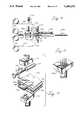
- FIG. 10is diagrammatic elevational view illustrating one method of assembly according to principles of the present invention.
- FIG. 11is a perspective view of a tool die of a type used to fabricate the neck seal illustrated in FIG. 7;
- FIG. 12is a perspective view of a portion of the apparatus illustrated in FIG. 10, used to fabricate a neck seal of the type illustrated in FIG. 1;
- FIG. 13is a schematic elevational view of an alternative assembly method with balloon making equipment illustrated in a first position
- FIG. 14is a view similar to FIG. 13, but showing the balloon-making equipment moved to a second position, with ends of the balloon films being held stationary.
- the balloon assembly 10includes a pair of overlying balloon films 12, 14 having neck portions 16 and body portions 20.
- the neck portionsare of a generally rectangular elongated configuration with rounded ends 26 and opposed ends adjacent the generally circular body portions.
- the neck and body portionshave peripheral edges 30, 32, respectively which are blended together to form a continuous outline of the finished balloon.
- the neck and body portionsare joined together by a peripheral seam 36 which follows the peripheral edges 30, 32.
- each balloon filmcomprises parts of an integral, one-piece film formed from a webbing of suitable material, such as MYLAR, and the seam 36 is formed using conventional techniques, preferably, by heat sealing the balloon films together.
- the die used for the heat sealinghas the outline of the overall balloon films visible in FIG. 1 and includes an outer cutting portion which cuts the balloon films out of the webbing of balloon film material, so as to have the peripheral configuration illustrated in FIG. 1.
- the upper balloon film 12has a circular opening 40 formed therein so that an inflating gas can be injected between the neck portions of the balloon films, to expand the body portions of the balloon films, to thereby inflate the balloon in a known manner.
- the balloon assembly 10includes an improved self-sealing flat film valve.
- the valveis generally indicated at 44, and preferably has an elongated, generally rectangular configuration.
- the valveis comprised of a pair of overlying valve film strips 46, 48 formed from a webbing of valve film material indicated at 50, as illustrated in FIGS. 1 and 2.
- the overlying valve film strips 46, 48are preferably formed from a single sheet of valve film material folded in half, lengthwise, along a fold line so as to form a first side edge 54, that folded edge located adjacent the center of the balloon body portions. If desired, however, the valve film strips 46, 48 can be formed from separate portions of valve film webbing generally coterminous with one another, and overlying one another, being aligned in registry. The valve film strips 46, 48 have free edges 56, 58 at the second side edge 60 of the valve, that edge remote from the center of the balloon film body portions. The portions of webbing 50, illustrated in FIGS.
- the webbing from which balloon films 12, 14 are formedhave edges parallel to the edges of webbing 50 and which extend the full height of the balloon films of FIG. 1 so that each balloon film can be formed as a separate unbroken piece from the film webbing.
- valve 44has a longitudinal center line or axis 64, extending in a generally horizontal direction in FIG. 2.
- the neck portions of the balloon filmshave a longitudinal center line axis 66 extending at an acute angle to the valve axis 64.
- the second side edge 60 of the valve filmextends at an angle to the neck axis 66.
- the neck axis 66 of the preferred embodimentpasses through the center C of the balloon film body portions, although such is not required by the present invention. It is also preferred that the valve be disposed between the neck of the balloon assembly and the center C of the balloon film body portions.
- the orientation of the valve film edge 60, at an angle to the neck axis 66allows manufacturing tolerances to be relaxed, thereby resulting in economies of manufacture.
- valve film strips 46, 48are joined together along valve seals 70, 72.
- the valve seal 70has a first end 74 extending from seam 36, adjacent the neck portion 16, and a free and 76 positioned between the balloon film body portions, at a point spaced from the seam 36.
- the second valve seal 72has a first end 78 extending from the folded side 54, and a second end 80 positioned adjacent the valve seal end 76, between balloon films 12, 14, and spaced from the peripheral seam 36.
- a generally V-shaped neck seal arrangement 86comprises a first seal 88 which crosses the neck axis 66, generally at the juncture of the neck and body portions of the balloon films.
- the neck seal 88 in the embodiment of FIGS. 1-3crosses the neck axis at a generally right angle, although such is not required and crossing at other angles are possible.
- the neck seal arrangement 86further includes a second neck seal 90 which extends adjacent the valve side edge 60. It is generally preferred that the neck seal 90 be positioned as close to the valve side edge 60 as possible, but according to one advantage of the present invention, the neck seal 90 can be spaced at small distances from the side edge 60, without impairing inflation of the balloon assembly.
- the neck seals 88, 90do not extend through the four layers of the balloon assembly.
- a pair of neck seals 88, 90are employed.
- the first neck seals 88, 90join the upper valve film strip 46 to the upper balloon film 12, and a separate, second set of neck seals 88, 90 joins the lower valve film strip 48 to the lower balloon film 14.
- a gap 94 between the valve film strips 46, 48is maintained throughout the length of valve 44, beginning at the valve inlet 96, located at that portion of the side edge 60 lying within the neck portion of the balloon assembly.
- the neck seals 88, 90extend to the peripheral seam 36, or at a point immediately adjacent thereto, to prevent air leakage past the neck seal arrangement.
- valve inlet 96It is important that gas entering the valve inlet 96 does not force the free edge 60 of the valve films together, so an to close off or reduce the valve inlet opening.
- great carehas been taken to insure that the neck seals of a balloon were properly spaced with respect to the balloon film edges, with a high degree of accuracy.
- economies of manufactureare possible because the accuracy of the neck seal placement can be relaxed to some extent. This is made possible by the valve film edge at the valve inlet, passing at an angle to the neck axis.
- the valve seals 70, 72define a path for incoming gas, directing the gas between the body portions of the balloon films.
- the first edge 54 of the valveis closed and comprises a fold line in the valve film web, dividing the web into first and second valve film strips 46, 48.
- the valve seal 80has a rounded end 78 originating at the edge 54.
- the valve seal 70has a rounded edge 74 originating at peripheral seam 36, the rounded ends 74, 78 being located adjacent the juncture of the balloon film neck and body portions.
- the valve sealsform a continuous channel from a point adjacent the neck portion, to a point interior of the balloon film body portions.
- Incoming gas emerging from the ends 76, 80 of the valve seal 70, 72is confined by the edge 54 of the valve films and portions of the peripheral seas 36 located at the right-hand end of the valve 44.
- the valve edge 60is open, and incoming gas enters between the balloon film body portions through the valve outlet 100, that portion of valve edge 60 lying between the free ends 76, 80 of the valve seals 70, 72 and that portion of the peripheral seam 36 which seals the ends of the valve film strips which are remote from the neck.
- the valve film strips 46, 48could be separately formed, with the edge 54 being open.
- the valve outletwould further include that portion of edge 54 lying between the free ends 76, 80 of the valve seals 70, 72 and the peripheral seam 36.
- the ends of the valve sealsespecially the upstream ends 74, 78 need not be precisely located at a particular point with respect to the balloon films 12, 14.
- neither the valve seals nor the neck sealsmust be located with a high degree of accuracy. It is important, however, that the neck seal 90 be located close enough to edge 60 of the valve lying in the neck portion so as to prevent portions of the edge 60 lying to one side of the valve seal from closing together when gas is injected through opening 40.
- the neck seal 90has a free end 102 which extends to peripheral seam 36, to prevent gas leakage at that end of the valve inlet.
- the remainder of the neck seal 90should be located at or adjacent the edge 60 to protect the valve inlet against collapse.
- the opposite end of the neck seal 90, that and located at the crotch of the "V"preferably intersects the peripheral seam 36, or is located immediately adjacent thereto.
- valve seal 88extends to edge 60 of the valve film, at a point immediately adjacent the peripheral edge 36, the end of the neck seal 90 adjacent the crotch of the "V" could be spaced from the peripheral seam 36, since the neck seal would operate to prevent gas leakage at the crotch of the V-shaped neck seal arrangement.
- valve seal 72could be eliminated if desired. However, in the preferred embodiment, the valve seal 72 in added to form a valve passageway of dimensions set by the tool die, thereby adding to the accuracy and precision throughout multiple production runs. If the valve is formed from a single folded sheet, the valve seal 72 may be omitted if desired. However, certain advantages can be obtained by providing a pair of valve scales, even if one side of the valve is closed, as in the preferred embodiment. For example, with the addition of valve seal 72, the valve seals could include undulating configurations, rather than the straight-line configurations illustrated in FIGS. 1-3, to provide a valved passageway defined by serpentine seals.
- the locations of the free ends of the valve sealsare not particularly critical to a successful performance of the balloon assembly, and an additional flexibility in manufacturing is also possible since the shape of the valve seals is not particularly critical to provide a self-sealing, flexible film valve meeting minimum requirements.
- valve seal arrangement 110is comprised of a plurality of generally parallel straight seals 112 extending across neck portions 16,, and preferably at generally right angles to the neck axis.
- the seals 112a and 112bare located adjacent portions of edge 60 which intersect the peripheral Bean 36.
- a plurality of intervening sealssupport intermediate portions of edge 60 against collapse at the valve inlet.
- the seal 112cis optional, and is provided in FIG. 4 to join the curved end 74 of valve seal 70 to a point on the balloon films at least immediately adjacent to peripheral seam 36. The remaining aspects of the balloon assembly of FIGS. 1-3 remain unchanged.
- Valve seals 120, 122have upstream ends 124, 126, respectively, adjacent the neck portion of the balloon and opposed outlet ends 130, 132, respectively, at the edge 60 of the valve. A valve outlet 134 is thereby formed at the edge 60, between the ends 130, 132 of the valve seal.
- the upstream ends of the valve sealsneed not intersect a seal of the neck seal arrangement at the peripheral seam of the balloon.
- the upstream end 124 of the valve seal 120is spaced from the nearest neck seal 112c.
- the valve sealscan extend into the neck portion of the balloon.
- the valve seal 122extends across four neck seals, and has an upstream end 126 remote from the juncture of the neck and body portions of the balloon.
- a neck seal arrangementis generally indicated at 140 comprising three neck seals 142.
- the portion of edge 60 lying in the neckhas the end portions and at least one intermediate portion thereof secured with a neck seal.
- the valve seals 146, 148are of generally straight-line configuration throughout. Since the valve seal 148 extends to edge seam 36, the valve film strips could be opened at the side edge 54, if desired.
- the valve film stripsare of a narrower dimension, such that the "in-board" edge 54 (that edge closest to the center) of the balloon film body portion is located at the juncture of the neck and body portions of the balloon films.
- the opposite, outboard edge 60lies just inside the edge seam 36 whereas in the embodiments of FIGS. 1-5, that edge was located outside of the balloon periphery, so as to extend outside of the finished balloon assembly between the neck and body portions thereof.
- the neck seal arrangement 152includes neck seals 154.
- One and neck seal, 154ais located in the juncture of the neck and body portions of the balloon, being located in the out-turned portions of the edge seas 36, beyond the parallel edges of the neck portion.
- the neck seal 154aprovides a redundant sealing of the edge 60 of the valve films adding to the sealing provided at the slight overlap of valve film edge 60 with the edge seam 36, indicated at 160. Since the valve seal 158 extends to edge seam 36, adjacent the neck portion of the balloon assembly, the opposite edge 54 of the valve films could be left opened, if desired.
- valve 170is formed from valve film strips 172 which are considerably wider than those of the preceding embodiments. As illustrated, the valve film strips 172 extend throughout the entire neck portion of the balloon.
- the neck seal arrangementis provided in two portions, generally indicated at 180 and 182, respectively.
- Each neck seal portion 180, 182is comprised of neck seals 184 extending generally at right angles to the neck axis.
- the first neck seal portion 180has seals securing the valve films and balloon films together, adjacent the entrance opening 40.
- the seal 184a visible in the opening 40is the lower neck seal, joining the lower valve and balloon films.
- the second portion of the neck seal arrangementis located in the neck portion of the films, adjacent the juncture of the neck and body portions of the balloon assembly.
- the valve and balloon filmsare joined at the edge seam 36, which provides support for the upstream portions of the valve passageway, beginning at the valve inlet located at opening 40.
- the valve seals 190, 192extend into the neck portion of the balloon assembly, although the valve seals could be terminated adjacent the juncture of the neck and body portions of the balloon films.
- the valve 170must include provision for an exit opening. It is preferred, in that regard, to terminate the valve films shorter than that previously described in FIG. 1 at a point interior of the balloon film body portions, spaced from the peripheral edge 36, which termination point will function as the valve outlet.
- FIGS. 10-12a first method of assembly of the balloon components will now be described.
- Four rolls of webbingare provided, with the two central rolls providing the webbing 56 for the valve film strips 46, 48 and the outer rolls providing webbing from which the balloon films are formed.
- the upper webbing 120is processed to form the upper balloon film 12, while the lower webbing 140 is processed to form the lower balloon film 14.
- Apparatus for manufacturing the balloon assemblyincludes a valve die 144 reciprocal in the vertical directions of arrow 146 by a connection to an actuator 148.
- the valve film strips 46, 48are pressed against a support die 150, to form the valve seals 70, 72.
- the valve die 144is heated to perform a heat-sealing operation to form the valve seal arrangements.
- the valve seal arrangementis formed between webbing for the balloon films.
- the webbing 120, 140 for the balloon filmsis guided over rollers 155, 157 so as to be closely spaced to the films 46, 48.
- Apparatus for fabricating the balloon assemblyfurther includes tool die members 161, 163 both of which are preferably moveable in vertical directions as indicated by the arrows in FIG. 10.
- the tool members 161, 163are preferably heated so as to heat seal the balloon films and valve film strips together to form the neck seal arrangements as described above. It is important that the valve film strips 46, 48 are not welded shut by the neck seal arrangements, and accordingly a barrier member 166 in interposed between the valve film strips 46, 48 during forming of the valve seal arrangement. Since the preferred method of forming the neck seal arrangements employs a heat-sealing technique, the barrier 166 preferably comprises a thermal barrier made of suitable material such as TEFLON, for example.
- valve seals and neck sealsare formed at substantially the same time, without movement of the film webbing.
- registration of the various sealsis provided by aligning the die members 144, 150 and 161, 163 thus providing a significant economy of manufacture.
- the valve seals and neck sealscould be made in sequence for a given balloon assembly, but in any event, neither the valve film strip nor the webbing for the balloon films need be moved.
- the neck sealsare formed first by bringing the die members 161, 163 together, and after the die members are separated, the barrier 166 is moved to the upstream position indicated in FIG. 10, adjacent the rolls providing a source of valve film strip material. Thereafter, the die member 144 is lowered against support 150 to form the neck seal arrangement.
- the four sheets of webbingare then advanced in the direction of arrow 142, being stored for future processing, or more preferably, being passed to a subsequent work station which forms the edge seam 36 and cuts the outer periphery of the balloon and valve film strips from their respective webbings.
- the barrier 166is advanced between the positions illustrated in FIG. 10, by a pneumatically operated cylinder 172 which is extended and retracted in the direction of arrow 174.
- the die member 163is provided with the V-shaped configuration of the neck seals of FIGS. 1 and 2.
- FIG. 11shows an alternative embodiment 163a of the die member for forming neck seals illustrated in FIGS. 7 and 8.
- FIGS. 13 and 14an alternative method of construction of the balloon assembly will be described.
- the balloon assembly illustrated in FIG. 1has a neck portion trailing behind the body portion, assuming web movement in the right-hand direction of FIG. 1.
- a balloon assembly with this orientationis fabricated using the method steps illustrated in FIGS. 13 and 14.
- the apparatus used to form the balloon assemblyis mounted to a common frame for movement in the direction of arrow 181, to the position illustrated in FIG. 14.
- the webbing for the various balloon films and valve film stripsin held stationary during the neck seal and valve seal steps.
- the die member 144is operated to form the valve seal in valve strips 46, 48.
- a numeral 185is applied to a portion of webbing 140 in contact with guide roller 157.
- the apparatus enclosed within the phantom lineis moved in a direction of arrow 181 to the position illustrated in FIG. 14, where the die members 161, 163 are operated to form the neck seal.
- the reference point 185 of the webbing 140is indicated in FIG. 14, to the right of die member 162.
- the guide rollers 155, 157travel in the direction of arrow 181
- the previously expanded portions of the outer webbing 120, 140are pressed together, in preparation for the neck sealing steps.
- the orientation of the pneumatic cylinder 172is displaced 90°, so that its direction of actuation is in a direction into and out of the plane of the paper on which FIGS. 13 and 14 are drawn.
- the balloon webbingis then advanced in a downstream direction in the right-hand direction, where the edge seam 36 is formed and the outer periphery of the balloon films and valve films is cut free from their respective webbing members.
Landscapes
- Engineering & Computer Science (AREA)
- Mechanical Engineering (AREA)
- General Engineering & Computer Science (AREA)
- Toys (AREA)
Abstract
Description
Claims (54)
Priority Applications (2)
| Application Number | Priority Date | Filing Date | Title |
|---|---|---|---|
| US07/702,790US5248275A (en) | 1991-05-20 | 1991-05-20 | Balloon with flat film valve and method of manufacture |
| US08/043,441US5378299A (en) | 1991-05-20 | 1993-04-05 | Method of making a balloon with flat film valve |
Applications Claiming Priority (1)
| Application Number | Priority Date | Filing Date | Title |
|---|---|---|---|
| US07/702,790US5248275A (en) | 1991-05-20 | 1991-05-20 | Balloon with flat film valve and method of manufacture |
Related Child Applications (1)
| Application Number | Title | Priority Date | Filing Date |
|---|---|---|---|
| US08/043,441DivisionUS5378299A (en) | 1991-05-20 | 1993-04-05 | Method of making a balloon with flat film valve |
Publications (1)
| Publication Number | Publication Date |
|---|---|
| US5248275Atrue US5248275A (en) | 1993-09-28 |
Family
ID=24822606
Family Applications (2)
| Application Number | Title | Priority Date | Filing Date |
|---|---|---|---|
| US07/702,790Expired - LifetimeUS5248275A (en) | 1991-05-20 | 1991-05-20 | Balloon with flat film valve and method of manufacture |
| US08/043,441Expired - Fee RelatedUS5378299A (en) | 1991-05-20 | 1993-04-05 | Method of making a balloon with flat film valve |
Family Applications After (1)
| Application Number | Title | Priority Date | Filing Date |
|---|---|---|---|
| US08/043,441Expired - Fee RelatedUS5378299A (en) | 1991-05-20 | 1993-04-05 | Method of making a balloon with flat film valve |
Country Status (1)
| Country | Link |
|---|---|
| US (2) | US5248275A (en) |
Cited By (46)
| Publication number | Priority date | Publication date | Assignee | Title |
|---|---|---|---|---|
| US5405479A (en)* | 1993-12-20 | 1995-04-11 | Cti Industries Corporation | Automatic valve insertion method |
| US5456716A (en)* | 1993-08-25 | 1995-10-10 | Pmt Corporation | Elastomeric valve assembly |
| US5460200A (en)* | 1994-11-14 | 1995-10-24 | Multi-Flex Seals, Inc. | Fluid flow check valve and method for making same |
| US5482492A (en)* | 1994-01-10 | 1996-01-09 | M & D Balloons, Inc. | Balloons and balloon valves |
| US5514431A (en)* | 1993-12-30 | 1996-05-07 | Dai Nippon Printing Co., Ltd. | Air bag and method for making the air bag |
| US5538573A (en)* | 1994-12-02 | 1996-07-23 | Cti Industries Corporation | Automatic valve insertion method and apparatus therefor |
| US5564143A (en)* | 1995-03-09 | 1996-10-15 | Dielectrics Industries | Check valve for fluid bladders |
| US5653464A (en)* | 1995-10-05 | 1997-08-05 | Automotive Technologies International Inc. | Airbag system with self shaping airbag |
| WO1997038252A1 (en)* | 1996-04-10 | 1997-10-16 | Ernesto Antonio Ramos Loza | Self-sealing valve for balloons or non elastomer articles, obtained by a mass production process |
| US5746446A (en)* | 1994-05-23 | 1998-05-05 | Automotive Technologies International, Inc. | Plastic film airbag |
| US5860441A (en)* | 1995-11-29 | 1999-01-19 | Convertidora Industries S.A. De C.V. | Self-sealing flexible plastic valve with curled inlet |
| US5863068A (en)* | 1994-05-23 | 1999-01-26 | Automotive Technologies International, Inc. | Plastic film airbag |
| US5878768A (en)* | 1995-10-10 | 1999-03-09 | Tarazaga Carrasco; Juan Jose | One way valve for inflatables and processes for production and incorporation in the inflatable |
| US5934310A (en)* | 1996-12-31 | 1999-08-10 | Littlehorn; Michael J. | Balloon valve and method of producing |
| US6149194A (en)* | 1994-05-23 | 2000-11-21 | Automotive Technologies International, Inc. | Plastic film airbag |
| US6170513B1 (en)* | 1999-10-14 | 2001-01-09 | Luke Lo | Inflation nozzle structure of an inflatable envelope |
| US6196260B1 (en)* | 1998-10-21 | 2001-03-06 | Dielectrics Industries, Inc. | Flow control valve |
| US6247488B1 (en)* | 1996-07-09 | 2001-06-19 | Bengt Peterson | Non return valve system and method for forming said non return valve system |
| US6250668B1 (en) | 1994-05-23 | 2001-06-26 | Automotive Technologies International, Inc. | Tubular airbag, method of making the same and occupant protection system including the same |
| US6352526B1 (en)* | 1999-11-12 | 2002-03-05 | Cawood Family Limited Partnership | Anti-reflux valve for collection bags |
| US6378552B1 (en) | 2000-11-10 | 2002-04-30 | Dielectrics Industries, Inc. | Dual speed flow control valve |
| US6632120B2 (en) | 2002-02-20 | 2003-10-14 | Sing-A-Tune Balloons, Llc | Balloon and method of connecting objects to one of two sheets forming the balloon |
| US20030229263A1 (en)* | 2000-04-14 | 2003-12-11 | Connors Kevin G. | Treatment of patients with a compressible attenuation device |
| US20030229264A1 (en)* | 2000-04-14 | 2003-12-11 | Connors Kevin G. | Implantable self-inflating attenuation device |
| US6715790B2 (en) | 1994-05-23 | 2004-04-06 | Automotive Technologies International, Inc. | Side curtain air bag |
| US20040064892A1 (en)* | 2002-10-03 | 2004-04-08 | Little Rapids Corporation | Inflatable article |
| US20040068830A1 (en)* | 2002-10-10 | 2004-04-15 | Sandeman David Christopher | Wedges |
| US20040198149A1 (en)* | 2003-01-14 | 2004-10-07 | Gerd Lippens | Inflatable non-latex balloon |
| US20060201549A1 (en)* | 2005-03-10 | 2006-09-14 | Akira Nakamura | Check-valve for reduction of leakage caused by valve flapping |
| US20060275565A1 (en)* | 2005-06-03 | 2006-12-07 | Jose De Jesus Michel Velasco | Autoblock valve for non latex type baloons |
| US20070037472A1 (en)* | 2005-07-29 | 2007-02-15 | Greenwald Robert E | Balloon with a pocket and method of making |
| US20070056647A1 (en)* | 2005-09-12 | 2007-03-15 | Sealed Air Corporation (Us) | Flexible valves |
| US20070156167A1 (en)* | 2000-04-14 | 2007-07-05 | Connors Kevin G | Pressure attenuation device |
| US20070225753A1 (en)* | 2000-11-27 | 2007-09-27 | Connors Kevin G | Attenuation device for treating glaucoma |
| US20100222802A1 (en)* | 2000-04-14 | 2010-09-02 | Attenuex Technologies, Inc. | Implant with high vapor pressure medium |
| USD627527S1 (en)* | 2008-07-08 | 2010-11-16 | Radio Systems Corporation | Pet bed heating pad |
| USD695848S1 (en)* | 2012-06-14 | 2013-12-17 | Northstar Balloons, LLC. | Balloon letters and numbers |
| US20140046123A1 (en)* | 2012-08-10 | 2014-02-13 | Attenuex Technologies, Inc. | Methods and systems for performing a medical procedure |
| US9415321B2 (en) | 2012-11-21 | 2016-08-16 | Jerome A. Harris | Self-sealing balloon or bladder |
| US9561134B2 (en) | 2011-09-14 | 2017-02-07 | Matthew T. Scholz | Positive pressure medical dressings with valve and kits containing same |
| US10030661B2 (en)* | 2014-08-18 | 2018-07-24 | Aisan Kogyo Kabushiki Kaisha | Electric pump |
| US20180236366A1 (en)* | 2015-09-11 | 2018-08-23 | Takara Kosan Co., Ltd. | Balloon |
| US10327880B2 (en) | 2000-04-14 | 2019-06-25 | Attenuex Technologies, Inc. | Attenuation device for use in an anatomical structure |
| US11129928B2 (en)* | 2016-07-06 | 2021-09-28 | Serres Oy | Assembly for collecting fluid during a medical or a surgical operation |
| US11197981B2 (en) | 2019-02-07 | 2021-12-14 | Solace Therapeutics, Inc. | Pressure attenuation device |
| US12070544B2 (en)* | 2010-09-20 | 2024-08-27 | Smith & Nephew Plc | Negative pressure device |
Families Citing this family (3)
| Publication number | Priority date | Publication date | Assignee | Title |
|---|---|---|---|---|
| US6602105B1 (en) | 1998-10-21 | 2003-08-05 | Michael Sussell | Illumination system for balloons with thin film valves |
| ES1050408Y (en)* | 2001-10-26 | 2002-07-16 | Carrasco Juan Jose Tarazaga | UNIDIRECTIONAL LAMINAR VALVE FOR INFLATABLE BODIES. |
| US20050164597A1 (en)* | 2004-01-23 | 2005-07-28 | Tripoli Melchiore (Mike) Iii | System and method for attaching components within an inflatable object |
Citations (21)
| Publication number | Priority date | Publication date | Assignee | Title |
|---|---|---|---|---|
| US1625394A (en)* | 1924-05-12 | 1927-04-19 | Paramount Rubber Cons Inc | Method of making hollow rubber articles |
| US1702974A (en)* | 1928-05-12 | 1929-02-19 | Spalding & Bros Ag | Collapsible valve and method of making same |
| US2597924A (en)* | 1950-10-04 | 1952-05-27 | William F Davenport | Self-sealing valve for inflatable pneumatic bladders or the like |
| US2700980A (en)* | 1950-08-02 | 1955-02-01 | Goodrich Co B F | Flexible valve and the like |
| US2864201A (en)* | 1956-01-16 | 1958-12-16 | Ralph G Leise | Inflated discus |
| US3006257A (en)* | 1956-10-02 | 1961-10-31 | Plastus Sa | Method for producing bags and the like containers of thermo-weldable material through welding of elementary component parts |
| US3149017A (en)* | 1961-05-24 | 1964-09-15 | Grace W R & Co | Polyethylene balloon |
| US3207420A (en)* | 1964-05-19 | 1965-09-21 | Octaviano D Navarrete-Kindelan | Container |
| US3230663A (en)* | 1962-10-01 | 1966-01-25 | Cons Thermoplastics Company | Inflatable article with integral valve |
| US3332415A (en)* | 1964-04-30 | 1967-07-25 | Kendall & Co | Self-sealing pressure valve for inflatable splints and other devices |
| US3392077A (en)* | 1965-01-25 | 1968-07-09 | Vision Wrap Ind Inc | Apparatus and method for the production of grommet bags |
| US3664058A (en)* | 1971-04-19 | 1972-05-23 | Bernard F Brieske | Inflatable plastic structures |
| US4290763A (en)* | 1979-06-15 | 1981-09-22 | Hurst Gerald L | Method for producing enclosed multipaneled envelopes |
| US4674532A (en)* | 1984-10-30 | 1987-06-23 | Toshimichi Koyanagi | Check valve |
| US4708167A (en)* | 1985-12-04 | 1987-11-24 | Toshimichi Koyanagi | Check valve |
| US4758198A (en)* | 1986-09-18 | 1988-07-19 | Ringstone Co., Ltd. | Gas-inflatable toy with plural bladders and valve means |
| US4842007A (en)* | 1988-09-08 | 1989-06-27 | Guard Associates, Inc. | Self-sealing valve for inflated bodies |
| US4850912A (en)* | 1987-10-30 | 1989-07-25 | Toshimichi Koyanagi | Container for sealingly containing a fluid |
| US4917646A (en)* | 1988-08-17 | 1990-04-17 | Kieves G | Self-sealing valve, a self-sealing, non-latex balloon, and a method for producing such a balloon |
| US4983138A (en)* | 1988-11-01 | 1991-01-08 | Mcgrath John | Inflatable container with self-sealing valve |
| JPH05211898A (en)* | 1990-01-19 | 1993-08-24 | F Hoffmann La Roche Ag | Method for detecting aquatic microbial pathogens and indicator microorganisms for human fecal contamination in water samples and kits therefor |
Family Cites Families (21)
| Publication number | Priority date | Publication date | Assignee | Title |
|---|---|---|---|---|
| DE219440C (en)* | ||||
| US564502A (en)* | 1896-07-21 | Warwick brookes | ||
| US379451A (en)* | 1888-03-13 | crane | ||
| US1151093A (en)* | 1914-11-24 | 1915-08-24 | Arthur H Du Bois | Toy balloon. |
| US1885917A (en)* | 1928-06-29 | 1932-11-01 | Kelemen Lewis | Inflatable rubber article |
| US2631957A (en)* | 1946-03-07 | 1953-03-17 | American Viscose Corp | Thread-reinforced films and methods of making them |
| US2662724A (en)* | 1948-12-27 | 1953-12-15 | Kravagna Cut | Check valve |
| US2713746A (en)* | 1950-03-17 | 1955-07-26 | Haugh Gordon Alexander | Hollow object and method of making thermoplastic seam |
| US2752594A (en)* | 1953-03-19 | 1956-06-26 | John C Link | Radar reflector |
| US2954048A (en)* | 1959-02-05 | 1960-09-27 | Frank J Rychlik | Pump and valve therefor |
| US3030640A (en)* | 1960-01-13 | 1962-04-24 | Air Pillow & Cushions Inc | Inflated articles |
| US3133696A (en)* | 1962-02-19 | 1964-05-19 | Holiday Line Inc | Pump |
| US3260017A (en)* | 1964-04-17 | 1966-07-12 | Robert A Wolfe | Electrically actuated toy space station having lamp means |
| US3585095A (en)* | 1968-07-11 | 1971-06-15 | Vision Wrap Ind Inc | System for producing grommet bags |
| US3717174A (en)* | 1971-08-03 | 1973-02-20 | R Dewall | Perfusion safety valve |
| US3759289A (en)* | 1971-08-03 | 1973-09-18 | Wall R De | Perfusion safety valve |
| US3980260A (en)* | 1973-04-04 | 1976-09-14 | Vonco Products, Inc. | Inflatable kite |
| US4077588A (en)* | 1975-09-15 | 1978-03-07 | Hurst Gerald L | Permanently buoyant balloon |
| US4127909A (en)* | 1976-09-27 | 1978-12-05 | C. J. Hendry Company | Inflatable raft construction and method |
| US4761197A (en)* | 1986-07-28 | 1988-08-02 | Baxter Travenol Laboratories, Inc. | Apparatus for sealing a web of film |
| US4976649A (en)* | 1990-06-04 | 1990-12-11 | C. M. Offray & Son, Inc. | Decorative balloon structure |
- 1991
- 1991-05-20USUS07/702,790patent/US5248275A/ennot_activeExpired - Lifetime
- 1993
- 1993-04-05USUS08/043,441patent/US5378299A/ennot_activeExpired - Fee Related
Patent Citations (21)
| Publication number | Priority date | Publication date | Assignee | Title |
|---|---|---|---|---|
| US1625394A (en)* | 1924-05-12 | 1927-04-19 | Paramount Rubber Cons Inc | Method of making hollow rubber articles |
| US1702974A (en)* | 1928-05-12 | 1929-02-19 | Spalding & Bros Ag | Collapsible valve and method of making same |
| US2700980A (en)* | 1950-08-02 | 1955-02-01 | Goodrich Co B F | Flexible valve and the like |
| US2597924A (en)* | 1950-10-04 | 1952-05-27 | William F Davenport | Self-sealing valve for inflatable pneumatic bladders or the like |
| US2864201A (en)* | 1956-01-16 | 1958-12-16 | Ralph G Leise | Inflated discus |
| US3006257A (en)* | 1956-10-02 | 1961-10-31 | Plastus Sa | Method for producing bags and the like containers of thermo-weldable material through welding of elementary component parts |
| US3149017A (en)* | 1961-05-24 | 1964-09-15 | Grace W R & Co | Polyethylene balloon |
| US3230663A (en)* | 1962-10-01 | 1966-01-25 | Cons Thermoplastics Company | Inflatable article with integral valve |
| US3332415A (en)* | 1964-04-30 | 1967-07-25 | Kendall & Co | Self-sealing pressure valve for inflatable splints and other devices |
| US3207420A (en)* | 1964-05-19 | 1965-09-21 | Octaviano D Navarrete-Kindelan | Container |
| US3392077A (en)* | 1965-01-25 | 1968-07-09 | Vision Wrap Ind Inc | Apparatus and method for the production of grommet bags |
| US3664058A (en)* | 1971-04-19 | 1972-05-23 | Bernard F Brieske | Inflatable plastic structures |
| US4290763A (en)* | 1979-06-15 | 1981-09-22 | Hurst Gerald L | Method for producing enclosed multipaneled envelopes |
| US4674532A (en)* | 1984-10-30 | 1987-06-23 | Toshimichi Koyanagi | Check valve |
| US4708167A (en)* | 1985-12-04 | 1987-11-24 | Toshimichi Koyanagi | Check valve |
| US4758198A (en)* | 1986-09-18 | 1988-07-19 | Ringstone Co., Ltd. | Gas-inflatable toy with plural bladders and valve means |
| US4850912A (en)* | 1987-10-30 | 1989-07-25 | Toshimichi Koyanagi | Container for sealingly containing a fluid |
| US4917646A (en)* | 1988-08-17 | 1990-04-17 | Kieves G | Self-sealing valve, a self-sealing, non-latex balloon, and a method for producing such a balloon |
| US4842007A (en)* | 1988-09-08 | 1989-06-27 | Guard Associates, Inc. | Self-sealing valve for inflated bodies |
| US4983138A (en)* | 1988-11-01 | 1991-01-08 | Mcgrath John | Inflatable container with self-sealing valve |
| JPH05211898A (en)* | 1990-01-19 | 1993-08-24 | F Hoffmann La Roche Ag | Method for detecting aquatic microbial pathogens and indicator microorganisms for human fecal contamination in water samples and kits therefor |
Cited By (91)
| Publication number | Priority date | Publication date | Assignee | Title |
|---|---|---|---|---|
| US5456716A (en)* | 1993-08-25 | 1995-10-10 | Pmt Corporation | Elastomeric valve assembly |
| US5405479A (en)* | 1993-12-20 | 1995-04-11 | Cti Industries Corporation | Automatic valve insertion method |
| US5514431A (en)* | 1993-12-30 | 1996-05-07 | Dai Nippon Printing Co., Ltd. | Air bag and method for making the air bag |
| US5482492A (en)* | 1994-01-10 | 1996-01-09 | M & D Balloons, Inc. | Balloons and balloon valves |
| US5595521A (en)* | 1994-01-10 | 1997-01-21 | M & D Balloons, Inc. | Balloons and balloon valves |
| US5863068A (en)* | 1994-05-23 | 1999-01-26 | Automotive Technologies International, Inc. | Plastic film airbag |
| US6715790B2 (en) | 1994-05-23 | 2004-04-06 | Automotive Technologies International, Inc. | Side curtain air bag |
| US6250668B1 (en) | 1994-05-23 | 2001-06-26 | Automotive Technologies International, Inc. | Tubular airbag, method of making the same and occupant protection system including the same |
| US5746446A (en)* | 1994-05-23 | 1998-05-05 | Automotive Technologies International, Inc. | Plastic film airbag |
| US6149194A (en)* | 1994-05-23 | 2000-11-21 | Automotive Technologies International, Inc. | Plastic film airbag |
| US5460200A (en)* | 1994-11-14 | 1995-10-24 | Multi-Flex Seals, Inc. | Fluid flow check valve and method for making same |
| US5538573A (en)* | 1994-12-02 | 1996-07-23 | Cti Industries Corporation | Automatic valve insertion method and apparatus therefor |
| US5564143A (en)* | 1995-03-09 | 1996-10-15 | Dielectrics Industries | Check valve for fluid bladders |
| US5653464A (en)* | 1995-10-05 | 1997-08-05 | Automotive Technologies International Inc. | Airbag system with self shaping airbag |
| US6027394A (en)* | 1995-10-10 | 2000-02-22 | Tarazaga Carrasco; Juan Jose | One way valve for inflatables and process for production and incorporation in the inflatable |
| US5878768A (en)* | 1995-10-10 | 1999-03-09 | Tarazaga Carrasco; Juan Jose | One way valve for inflatables and processes for production and incorporation in the inflatable |
| US5860441A (en)* | 1995-11-29 | 1999-01-19 | Convertidora Industries S.A. De C.V. | Self-sealing flexible plastic valve with curled inlet |
| US6015601A (en)* | 1995-11-29 | 2000-01-18 | Convertidora Industrial S.A. De C.V. | Curling ribbon |
| US6015472A (en)* | 1995-11-29 | 2000-01-18 | Convertidora Industrial S.A. De C.V. | Method of producing a balloon with a self-sealing valve |
| US6192917B1 (en) | 1996-04-10 | 2001-02-27 | Ernesto Antonio Ramos Loza | Self-sealing valve for balloons or non elastomer articles, obtained by a mass production process |
| WO1997038252A1 (en)* | 1996-04-10 | 1997-10-16 | Ernesto Antonio Ramos Loza | Self-sealing valve for balloons or non elastomer articles, obtained by a mass production process |
| US6247488B1 (en)* | 1996-07-09 | 2001-06-19 | Bengt Peterson | Non return valve system and method for forming said non return valve system |
| US6042448A (en)* | 1996-12-31 | 2000-03-28 | Pro-Pak Industries, Inc. | Balloon valve and method of producing |
| US5934310A (en)* | 1996-12-31 | 1999-08-10 | Littlehorn; Michael J. | Balloon valve and method of producing |
| US6196260B1 (en)* | 1998-10-21 | 2001-03-06 | Dielectrics Industries, Inc. | Flow control valve |
| US6170513B1 (en)* | 1999-10-14 | 2001-01-09 | Luke Lo | Inflation nozzle structure of an inflatable envelope |
| US6352526B1 (en)* | 1999-11-12 | 2002-03-05 | Cawood Family Limited Partnership | Anti-reflux valve for collection bags |
| US6682473B1 (en) | 2000-04-14 | 2004-01-27 | Solace Therapeutics, Inc. | Devices and methods for attenuation of pressure waves in the body |
| US20090240277A1 (en)* | 2000-04-14 | 2009-09-24 | Attenuex Technologies,Inc. | Pressure attenuation device |
| US20030229264A1 (en)* | 2000-04-14 | 2003-12-11 | Connors Kevin G. | Implantable self-inflating attenuation device |
| US20030236442A1 (en)* | 2000-04-14 | 2003-12-25 | Connors Kevin G. | Implantable valved pressure attenuation device |
| US8858460B2 (en) | 2000-04-14 | 2014-10-14 | Attenuex Technologies, Inc. | Method and system for measuring leak point pressure in a bladder |
| US8961392B2 (en) | 2000-04-14 | 2015-02-24 | Attenuex Technologies, Inc. | Delivery system for inflatable implant |
| US9044209B2 (en) | 2000-04-14 | 2015-06-02 | Attenuex Technologies, Inc. | Method of removing an inflated implant |
| WO2004030518A2 (en) | 2000-04-14 | 2004-04-15 | Solace Therapeutics, Inc. | Implantable pressure attenuation device |
| US8574146B2 (en) | 2000-04-14 | 2013-11-05 | Attenuex Technologies, Inc. | Implant with high vapor pressure medium |
| US20040138520A1 (en)* | 2000-04-14 | 2004-07-15 | Connors Kevin G | High vapor pressure attenuation device |
| US8298132B2 (en) | 2000-04-14 | 2012-10-30 | Attenuex Technologies, Inc. | Method of treating benign hypertrophy of the prostate |
| US20050187427A1 (en)* | 2000-04-14 | 2005-08-25 | Connors Kevin G. | Method of treating benign hypertrophy of the prostate |
| US8025064B2 (en) | 2000-04-14 | 2011-09-27 | Kevin G Connors | Methods for attenuating pressure waves in a patient's eye |
| US6976951B2 (en) | 2000-04-14 | 2005-12-20 | Solace Therapeutics, Inc. | High vapor pressure attenuation device |
| US6976950B2 (en) | 2000-04-14 | 2005-12-20 | Solace Therapeutics, Inc. | Implantable valved pressure attenuation device |
| US6988983B2 (en) | 2000-04-14 | 2006-01-24 | Solace Therapeutics, Inc. | Implantable self-inflating attenuation device |
| US7074178B2 (en) | 2000-04-14 | 2006-07-11 | Solace Therapeutics, Inc. | Treatment of patients with a compressible attenuation device |
| US8016740B2 (en) | 2000-04-14 | 2011-09-13 | Attenuex Technologies, Inc. | Pressure attenuation device |
| US10383510B2 (en) | 2000-04-14 | 2019-08-20 | Solace Therapeutics, Inc. | Implant with high vapor pressure medium |
| US10327880B2 (en) | 2000-04-14 | 2019-06-25 | Attenuex Technologies, Inc. | Attenuation device for use in an anatomical structure |
| US9615911B2 (en) | 2000-04-14 | 2017-04-11 | Attenuex Technologies, Inc. | Delivery system for inflatable implant |
| US20070156167A1 (en)* | 2000-04-14 | 2007-07-05 | Connors Kevin G | Pressure attenuation device |
| US9427295B2 (en) | 2000-04-14 | 2016-08-30 | Attenuex Technologies, Inc. | Method of removing an inflated implant from a bladder |
| US7374532B2 (en) | 2000-04-14 | 2008-05-20 | Attenuex Technologies, Inc. | High vapor pressure attenuation device |
| US9498195B2 (en) | 2000-04-14 | 2016-11-22 | Attenuex Technologies, Inc. | Implant with high vapor pressure medium |
| US7470228B2 (en) | 2000-04-14 | 2008-12-30 | Attenuex Technologies, Inc. | Method of treating benign hypertrophy of the prostate |
| US20090105527A1 (en)* | 2000-04-14 | 2009-04-23 | Attenuex Technologies, Inc. | Method of treating benign hypertrophy of the prostate |
| US7540876B2 (en) | 2000-04-14 | 2009-06-02 | Attenuex Technologies, Inc. | Pressure attenuation device |
| US20030229263A1 (en)* | 2000-04-14 | 2003-12-11 | Connors Kevin G. | Treatment of patients with a compressible attenuation device |
| US20100222802A1 (en)* | 2000-04-14 | 2010-09-02 | Attenuex Technologies, Inc. | Implant with high vapor pressure medium |
| US6378552B1 (en) | 2000-11-10 | 2002-04-30 | Dielectrics Industries, Inc. | Dual speed flow control valve |
| US7691051B2 (en) | 2000-11-27 | 2010-04-06 | Cascade Ophthalmics, Inc. | Attenuation device for treating glaucoma |
| US20070225753A1 (en)* | 2000-11-27 | 2007-09-27 | Connors Kevin G | Attenuation device for treating glaucoma |
| US6632120B2 (en) | 2002-02-20 | 2003-10-14 | Sing-A-Tune Balloons, Llc | Balloon and method of connecting objects to one of two sheets forming the balloon |
| US6934989B2 (en) | 2002-10-03 | 2005-08-30 | Little Rapids Corporation | Inflatable article |
| US20040064892A1 (en)* | 2002-10-03 | 2004-04-08 | Little Rapids Corporation | Inflatable article |
| US20040068830A1 (en)* | 2002-10-10 | 2004-04-15 | Sandeman David Christopher | Wedges |
| US20040198149A1 (en)* | 2003-01-14 | 2004-10-07 | Gerd Lippens | Inflatable non-latex balloon |
| US20060201549A1 (en)* | 2005-03-10 | 2006-09-14 | Akira Nakamura | Check-valve for reduction of leakage caused by valve flapping |
| US7395833B2 (en)* | 2005-03-10 | 2008-07-08 | Akira Nakamura | Check-valve for reduction of leakage caused by valve flapping |
| US20060275565A1 (en)* | 2005-06-03 | 2006-12-07 | Jose De Jesus Michel Velasco | Autoblock valve for non latex type baloons |
| US20070037472A1 (en)* | 2005-07-29 | 2007-02-15 | Greenwald Robert E | Balloon with a pocket and method of making |
| US20070056647A1 (en)* | 2005-09-12 | 2007-03-15 | Sealed Air Corporation (Us) | Flexible valves |
| USD627527S1 (en)* | 2008-07-08 | 2010-11-16 | Radio Systems Corporation | Pet bed heating pad |
| US8721520B2 (en) | 2008-11-25 | 2014-05-13 | Attenuex Technologies, Inc. | Inflatable implant delivery system and method |
| US12070544B2 (en)* | 2010-09-20 | 2024-08-27 | Smith & Nephew Plc | Negative pressure device |
| US9561134B2 (en) | 2011-09-14 | 2017-02-07 | Matthew T. Scholz | Positive pressure medical dressings with valve and kits containing same |
| USD695848S1 (en)* | 2012-06-14 | 2013-12-17 | Northstar Balloons, LLC. | Balloon letters and numbers |
| US9801658B2 (en) | 2012-08-10 | 2017-10-31 | Attenuex Technologies, Inc. | Removal device |
| US10543071B2 (en) | 2012-08-10 | 2020-01-28 | Solace Therapeutics, Inc. | Methods and systems for performing a medical procedure |
| US8992412B2 (en) | 2012-08-10 | 2015-03-31 | Attenuex Technologies, Inc. | Removal device |
| US20140046123A1 (en)* | 2012-08-10 | 2014-02-13 | Attenuex Technologies, Inc. | Methods and systems for performing a medical procedure |
| US8864649B2 (en) | 2012-08-10 | 2014-10-21 | Attenuex Technologies, Inc. | Methods and systems for performing a medical procedure |
| US10799268B2 (en) | 2012-08-10 | 2020-10-13 | Solace Therapeutics, Inc. | Methods and systems for performing a medical procedure |
| US10531894B2 (en) | 2012-08-10 | 2020-01-14 | Solace Therapeutics, Inc. | Methods and systems for performing a medical procedure |
| US8894563B2 (en)* | 2012-08-10 | 2014-11-25 | Attenuex Technologies, Inc. | Methods and systems for performing a medical procedure |
| US8882653B2 (en) | 2012-08-10 | 2014-11-11 | Attenuex Technologies, Inc. | Methods and systems for performing a medical procedure |
| US9415321B2 (en) | 2012-11-21 | 2016-08-16 | Jerome A. Harris | Self-sealing balloon or bladder |
| US10030661B2 (en)* | 2014-08-18 | 2018-07-24 | Aisan Kogyo Kabushiki Kaisha | Electric pump |
| US10252174B2 (en)* | 2015-09-11 | 2019-04-09 | Takara Kosan Co., Ltd. | Balloon |
| US20180236366A1 (en)* | 2015-09-11 | 2018-08-23 | Takara Kosan Co., Ltd. | Balloon |
| US11129928B2 (en)* | 2016-07-06 | 2021-09-28 | Serres Oy | Assembly for collecting fluid during a medical or a surgical operation |
| US11285255B2 (en) | 2016-07-06 | 2022-03-29 | Serres Oy | Collection liner for a medical or a surgical operation |
| US11197981B2 (en) | 2019-02-07 | 2021-12-14 | Solace Therapeutics, Inc. | Pressure attenuation device |
Also Published As
| Publication number | Publication date |
|---|---|
| US5378299A (en) | 1995-01-03 |
Similar Documents
| Publication | Publication Date | Title |
|---|---|---|
| US5248275A (en) | Balloon with flat film valve and method of manufacture | |
| JP2667030B2 (en) | Self-sealing valves, self-sealing non-latex balloons and methods of making such balloons | |
| US5482492A (en) | Balloons and balloon valves | |
| US5860441A (en) | Self-sealing flexible plastic valve with curled inlet | |
| US5295892A (en) | Balloon having a self sealing valve and method of making same | |
| US2947653A (en) | Method of producing containers from thermoplastic material | |
| AU709717B2 (en) | One-way valve for inflatable bodies and processes for production and incorporation in the inflatable body | |
| US2256506A (en) | Method and apparatus for making bags | |
| JPH11504885A (en) | Expansion cushion and method of manufacturing the same | |
| JPH04154571A (en) | Stretchable air bag cushioning material sheet equipped with self seal type blow-in tube and its manufacture | |
| US4959114A (en) | Process for producing flattened gusseted tubing from flat plastic film | |
| US2537462A (en) | Method of making automatic bottom bags | |
| US5017254A (en) | Method of making inflatable bodies | |
| CA1054447A (en) | Stepped and angle-cut, pinch closure | |
| JP2587135B2 (en) | Self-sealing blow tube with multiple side-by-side passages for airbags | |
| US3943833A (en) | Production of lined valved bags | |
| JPH11216784A (en) | Bag with check valve | |
| JP2580384B2 (en) | Airbag self-sealing blow tube | |
| JPH06278695A (en) | Manufacture of envelope for airship or balloon by multi-division gore | |
| JPH01280491A (en) | Manufacture of floating body such as toy balloon, balloon or the like | |
| AU612882C (en) | Self-sealing valve for non-latex balloon | |
| JPH0360275U (en) | ||
| GB2381472A (en) | Balloons and manufacturing systems and method for producing balloons | |
| JPS597242Y2 (en) | Plastic film gusset bag | |
| MXPA97004167A (en) | Unidirectional valve for inflatable bodies and procedures for its manufacture and incorporation to the swelling body |
Legal Events
| Date | Code | Title | Description |
|---|---|---|---|
| AS | Assignment | Owner name:M & D BALLOONS, INC., A CORP. OF CA, CALIFORNIA Free format text:ASSIGNMENT OF ASSIGNORS INTEREST.;ASSIGNORS:MC GRATH, JOHN;COPE, DENNIS;HARRIS, SCOTT;AND OTHERS;REEL/FRAME:005780/0205;SIGNING DATES FROM 19910610 TO 19910624 | |
| STCF | Information on status: patent grant | Free format text:PATENTED CASE | |
| CC | Certificate of correction | ||
| AS | Assignment | Owner name:BALLOON ZONE WHOLESALE, INC., DELAWARE Free format text:SECURITY INTEREST;ASSIGNOR:M.&D. BALLOONS, INC.;REEL/FRAME:007656/0805 Effective date:19950831 | |
| FEPP | Fee payment procedure | Free format text:PAT HLDR NO LONGER CLAIMS SMALL ENT STAT AS INDIV INVENTOR (ORIGINAL EVENT CODE: LSM1); ENTITY STATUS OF PATENT OWNER: LARGE ENTITY | |
| FPAY | Fee payment | Year of fee payment:4 | |
| FEPP | Fee payment procedure | Free format text:PAYOR NUMBER ASSIGNED (ORIGINAL EVENT CODE: ASPN); ENTITY STATUS OF PATENT OWNER: LARGE ENTITY | |
| FPAY | Fee payment | Year of fee payment:8 | |
| AS | Assignment | Owner name:M & D FLEXOGRAPHIC PRINTERS, INC. (ILLINOIS), ILLI Free format text:AGREEMENT AND PLANE OF MERGER BETWEEN M & D FLEXOGRAPHIC PRINTERS, INC. & M & D BALLOONS, INCORPORATED;ASSIGNOR:M AND D BALLONS, INCORPORATED (CALIFORNIA);REEL/FRAME:012559/0401 Effective date:19931227 | |
| AS | Assignment | Owner name:FLEET NATIONAL BANK, AS COLLATERAL AGENT, MASSACHU Free format text:SECURITY AGREEMENT;ASSIGNOR:M&D BALLOONS, INC.;REEL/FRAME:012841/0513 Effective date:20020320 | |
| AS | Assignment | Owner name:GENERAL ELECTRIC CAPITAL CORPORATION, NEW YORK Free format text:SECOND AMENDED AND RESTATED PLEDGE AND SECURITY AGREEMENT;ASSIGNORS:AMSCAN HOLDINGS, INC.;AM-SOURCE, LLC;AMSCAN INC.;AND OTHERS;REEL/FRAME:013392/0001 Effective date:20021220 | |
| AS | Assignment | Owner name:AMSCAN HOLDINGS, INC., NEW YORK Free format text:RELEASE OF SECURITY AGREEMENT;ASSIGNOR:GENERAL ELECTRIC CAPITAL CORPORATION;REEL/FRAME:015320/0033 Effective date:20040430 Owner name:AMSCAN, INC., NEW YORK Free format text:RELEASE OF SECURITY AGREEMENT;ASSIGNOR:GENERAL ELECTRIC CAPITAL CORPORATION;REEL/FRAME:015320/0033 Effective date:20040430 Owner name:ANAGRAM EDEN PRAIRIE PROPERTY HOLDINGS, LLC, NEW Y Free format text:RELEASE OF SECURITY AGREEMENT;ASSIGNOR:GENERAL ELECTRIC CAPITAL CORPORATION;REEL/FRAME:015320/0033 Effective date:20040430 Owner name:ANAGRAM INTERNATIONAL HOLDINGS, INC., NEW YORK Free format text:RELEASE OF SECURITY AGREEMENT;ASSIGNOR:GENERAL ELECTRIC CAPITAL CORPORATION;REEL/FRAME:015320/0033 Effective date:20040430 Owner name:ANAGRAM INTERNATIONAL, INC., NEW YORK Free format text:RELEASE OF SECURITY AGREEMENT;ASSIGNOR:GENERAL ELECTRIC CAPITAL CORPORATION;REEL/FRAME:015320/0033 Effective date:20040430 Owner name:ANAGRAM INTERNATIONAL, LLC, NEW YORK Free format text:RELEASE OF SECURITY AGREEMENT;ASSIGNOR:GENERAL ELECTRIC CAPITAL CORPORATION;REEL/FRAME:015320/0033 Effective date:20040430 Owner name:JCS REALTY CORP., NEW YORK Free format text:RELEASE OF SECURITY AGREEMENT;ASSIGNOR:GENERAL ELECTRIC CAPITAL CORPORATION;REEL/FRAME:015320/0033 Effective date:20040430 Owner name:M&D INDUSTRIES, INC., NEW YORK Free format text:RELEASE OF SECURITY AGREEMENT;ASSIGNOR:GENERAL ELECTRIC CAPITAL CORPORATION;REEL/FRAME:015320/0033 Effective date:20040430 Owner name:SSY REALTY CORP., NEW YORK Free format text:RELEASE OF SECURITY AGREEMENT;ASSIGNOR:GENERAL ELECTRIC CAPITAL CORPORATION;REEL/FRAME:015320/0033 Effective date:20040430 Owner name:TRISAR, INC., NEW YORK Free format text:RELEASE OF SECURITY AGREEMENT;ASSIGNOR:GENERAL ELECTRIC CAPITAL CORPORATION;REEL/FRAME:015320/0033 Effective date:20040430 | |
| AS | Assignment | Owner name:GENERAL ELECTRIC CAPITAL CORPORATION, CONNECTICUT Free format text:SECURITY AGREEMENT;ASSIGNOR:M&D INDUSTRIES, INC. F/K/A M&D BALLONS, INC.;REEL/FRAME:015328/0137 Effective date:20040430 | |
| FPAY | Fee payment | Year of fee payment:12 | |
| AS | Assignment | Owner name:AMSCAN INC., NEW YORK Free format text:RELEASE OF SECURITY INTEREST IN PATENTS;ASSIGNOR:GENERAL ELECTRIC CAPITAL CORPORATION AS COLLATERAL AGENT;REEL/FRAME:017025/0197 Effective date:20051223 Owner name:AM-SOURCE, LLC, NEW YORK Free format text:RELEASE OF SECURITY INTEREST IN PATENTS;ASSIGNOR:GENERAL ELECTRIC CAPITAL CORPORATION AS COLLATERAL AGENT;REEL/FRAME:017025/0197 Effective date:20051223 Owner name:ANAGRAM INTERNATIONAL, INC., NEW YORK Free format text:RELEASE OF SECURITY INTEREST IN PATENTS;ASSIGNOR:GENERAL ELECTRIC CAPITAL CORPORATION AS COLLATERAL AGENT;REEL/FRAME:017025/0197 Effective date:20051223 Owner name:M&D INDUSTRIES, INC., NEW YORK Free format text:RELEASE OF SECURITY INTEREST IN PATENTS;ASSIGNOR:GENERAL ELECTRIC CAPITAL CORPORATION AS COLLATERAL AGENT;REEL/FRAME:017025/0197 Effective date:20051223 | |
| AS | Assignment | Owner name:GENERAL ELECTRIC CAPITAL CORPORATION AS COLLATERAL Free format text:FIRST LIEN PATENT SECURITY AGREEMENT;ASSIGNORS:AMSCAN INC.;ANAGRAM INTERNATIONAL, INC.;AM-SOURCE, LLC;AND OTHERS;REEL/FRAME:017025/0375 Effective date:20051223 Owner name:GOLDMAN SACHS CREDIT PARTNERS L.P., AS COLLATERAL Free format text:SECOND LIEN PATENT SECURITY AGREEMENT;ASSIGNORS:AMSCAN INC.;AM-SOURCE, LLC;ANAGRAM INTERNATIONAL, INC.;AND OTHERS;REEL/FRAME:017025/0868 Effective date:20051223 | |
| AS | Assignment | Owner name:M&D INDUSTRIES, INC., NEW YORK Free format text:RELEASE OF FIRST LIEN SECURITY AGREEMENT IN PATENTS;ASSIGNOR:GENERAL ELECTRIC CAPITAL CORPORATION;REEL/FRAME:019489/0406 Effective date:20070525 Owner name:AMSCAN INC., NEW YORK Free format text:RELEASE OF SECOND LIEN SECURITY AGREEMENT IN PATENTS;ASSIGNOR:GOLDMAN SACHS CREDIT PARTNERS, L.P.;REEL/FRAME:019489/0448 Effective date:20070525 Owner name:ANAGRAM INTERNATIONAL, INC., NEW YORK Free format text:RELEASE OF SECOND LIEN SECURITY AGREEMENT IN PATENTS;ASSIGNOR:GOLDMAN SACHS CREDIT PARTNERS, L.P.;REEL/FRAME:019489/0448 Effective date:20070525 Owner name:AM-SOURCE, LLC, NEW YORK Free format text:RELEASE OF SECOND LIEN SECURITY AGREEMENT IN PATENTS;ASSIGNOR:GOLDMAN SACHS CREDIT PARTNERS, L.P.;REEL/FRAME:019489/0448 Effective date:20070525 Owner name:M&D INDUSTRIES, INC., NEW YORK Free format text:RELEASE OF SECOND LIEN SECURITY AGREEMENT IN PATENTS;ASSIGNOR:GOLDMAN SACHS CREDIT PARTNERS, L.P.;REEL/FRAME:019489/0448 Effective date:20070525 Owner name:ANAGRAM INTERNATIONAL, INC., NEW YORK Free format text:RELEASE OF FIRST LIEN SECURITY AGREEMENT IN PATENTS;ASSIGNOR:GENERAL ELECTRIC CAPITAL CORPORATION;REEL/FRAME:019489/0406 Effective date:20070525 Owner name:CREDIT SUISSE, NEW YORK Free format text:SECOND LIEN PATENT SECURITY AGREEMENT;ASSIGNORS:AMSCAN INC.;ANAGRAM INTERNATIONAL, INC.;M&D INDUSTRIES, INC.;REEL/FRAME:019489/0531 Effective date:20070525 Owner name:BANK OF AMERICA, N.A., NEW YORK Free format text:FIRST LIEN PATENT SECURITY AGREEMENT;ASSIGNORS:AMSCAN INC.;ANAGRAM INTERNATIONAL, INC.;M&D INDUSTRIES, INC.;REEL/FRAME:019489/0462 Effective date:20070525 Owner name:AM-SOURCE, LLC, NEW YORK Free format text:RELEASE OF FIRST LIEN SECURITY AGREEMENT IN PATENTS;ASSIGNOR:GENERAL ELECTRIC CAPITAL CORPORATION;REEL/FRAME:019489/0406 Effective date:20070525 Owner name:AMSCAN INC., NEW YORK Free format text:RELEASE OF FIRST LIEN SECURITY AGREEMENT IN PATENTS;ASSIGNOR:GENERAL ELECTRIC CAPITAL CORPORATION;REEL/FRAME:019489/0406 Effective date:20070525 | |
| AS | Assignment | Owner name:M&D INDUSTRIES, INC., NEW YORK Free format text:RELEASE OF LIEN ON PATENTS;ASSIGNOR:BANK OF AMERICA, N.A.;REEL/FRAME:024838/0208 Effective date:20100813 Owner name:AM-SOURCE, LLC, NEW YORK Free format text:RELEASE OF LIEN ON PATENTS;ASSIGNOR:BANK OF AMERICA, N.A.;REEL/FRAME:024838/0208 Effective date:20100813 Owner name:ANAGRAM INTERNATIONAL, INC., NEW YORK Free format text:RELEASE OF LIEN ON PATENTS;ASSIGNOR:BANK OF AMERICA, N.A.;REEL/FRAME:024838/0208 Effective date:20100813 Owner name:AMSCAN INC., NEW YORK Free format text:RELEASE OF LIEN ON PATENTS;ASSIGNOR:BANK OF AMERICA, N.A.;REEL/FRAME:024838/0208 Effective date:20100813 | |
| AS | Assignment | Owner name:WELLS FARGO RETAIL FINANCE, LLC, MASSACHUSETTS Free format text:SECURITY INTEREST;ASSIGNORS:AMSCAN INC.;ANAGRAM INTERNATIONAL, INC.;M&D INDUSTRIES, INC.;REEL/FRAME:024850/0459 Effective date:20100813 | |
| AS | Assignment | Owner name:CREDIT SUISSE AG, CAYMAN ISLANDS BRANCH, NEW YORK Free format text:CORRECTIVE ASSIGNMENT TO CORRECT THE PAGE ONE OF THE PATENT SECURITY AGREEMENT PREVIOUSLY RECORDED ON REEL 019489 FRAME 0531. ASSIGNOR(S) HEREBY CONFIRMS THE "SECOND LIEN PATENT SECURITY AGREEMENT" IS TO BECOME "PATENT SECURITY AGREEMENT";ASSIGNORS:AMSCAN INC.;ANAGRAM INTERNATIONAL, INC.;M&D INDUSTRIES, INC.;REEL/FRAME:025161/0908 Effective date:20100813 | |
| AS | Assignment | Owner name:M&D INDUSTRIES, INC., NEW YORK Free format text:RELEASE OF LIEN ON PATENTS;ASSIGNOR:CREDIT SUISSE AG;REEL/FRAME:025437/0966 Effective date:20101202 Owner name:AMSCAN INC., NEW YORK Free format text:RELEASE OF LIEN ON PATENTS;ASSIGNOR:CREDIT SUISSE AG;REEL/FRAME:025437/0966 Effective date:20101202 Owner name:ANAGRAM INTERNATIONAL, INC., MINNESOTA Free format text:RELEASE OF LIEN ON PATENTS;ASSIGNOR:CREDIT SUISSE AG;REEL/FRAME:025437/0966 Effective date:20101202 | |
| AS | Assignment | Owner name:CREDIT SUISSE AG, NEW YORK Free format text:PATENT SECURITY AGREEMENT;ASSIGNORS:AMSCAN INC.;ANAGRAM INTERNATIONAL, INC.;M&D INDUSTRIES, INC.;REEL/FRAME:025441/0457 Effective date:20101202 | |
| AS | Assignment | Owner name:DEUTSCHE BANK TRUST COMPANY AMERICAS, NEW YORK Free format text:GRANT OF SECURITY INTEREST IN US PATENTS (ABL SECURITY AGREEMENT);ASSIGNORS:AMSCAN, INC.;AM-SOURCE, INC.;ANAGRAM INTERNATIONAL, INC.;AND OTHERS;REEL/FRAME:028652/0714 Effective date:20120727 Owner name:DEUTSCHE BANK TRUST COMPANY AMERICAS, NEW YORK Free format text:GRANT OF SECURITY INTEREST IN US PATENTS (TERM LOAN SECURITY AGREEMENT);ASSIGNORS:AMSCAN, INC.;AM-SOURCE, INC.;ANAGRAM INTERNATIONAL, INC.;AND OTHERS;REEL/FRAME:028652/0979 Effective date:20120727 Owner name:AMSCAN, INC., NEW YORK Free format text:RELEASE BY SECURED PARTY;ASSIGNOR:WELLS FARGO BANK, NATIONAL ASSOCIATION, SUCCESSOR BY MERGER TO WELLS FARGO RETAIL FINANCE, LLC;REEL/FRAME:028659/0469 Effective date:20120727 Owner name:M&D INDUSTRIES, INC., NEW YORK Free format text:RELEASE BY SECURED PARTY;ASSIGNOR:CREDIT SUISSE AG, AS COLLATERAL AGENT;REEL/FRAME:028659/0593 Effective date:20120727 Owner name:AMSCAN, INC., NEW YORK Free format text:RELEASE BY SECURED PARTY;ASSIGNOR:CREDIT SUISSE AG, AS COLLATERAL AGENT;REEL/FRAME:028659/0593 Effective date:20120727 Owner name:ANAGRAM INTERNATIONAL, INC., MINNESOTA Free format text:RELEASE BY SECURED PARTY;ASSIGNOR:CREDIT SUISSE AG, AS COLLATERAL AGENT;REEL/FRAME:028659/0593 Effective date:20120727 Owner name:ANAGRAM INTERNATIONAL, INC., MINNESOTA Free format text:RELEASE BY SECURED PARTY;ASSIGNOR:WELLS FARGO BANK, NATIONAL ASSOCIATION, SUCCESSOR BY MERGER TO WELLS FARGO RETAIL FINANCE, LLC;REEL/FRAME:028659/0469 Effective date:20120727 Owner name:M&D INDUSTRIES, INC., NEW YORK Free format text:RELEASE BY SECURED PARTY;ASSIGNOR:WELLS FARGO BANK, NATIONAL ASSOCIATION, SUCCESSOR BY MERGER TO WELLS FARGO RETAIL FINANCE, LLC;REEL/FRAME:028659/0469 Effective date:20120727 | |
| AS | Assignment | Owner name:BALLOON ZONE WHOLESALE, INC., DELAWARE Free format text:ASSIGNMENT OF ASSIGNORS INTEREST;ASSIGNOR:M.&D. BALLOONS, INC.;REEL/FRAME:028989/0908 Effective date:19950831 | |
| AS | Assignment | Owner name:ANAGRAM INTERNATIONAL, INC., MINNESOTA Free format text:RELEASE BY SECURED PARTY;ASSIGNOR:BANK OF AMERICA, N.A., AS SUCCESSOR BY MERGER TO FLEET NATIONAL BANK;REEL/FRAME:028999/0152 Effective date:20120919 Owner name:M&D BALLOONS, INC., NEW YORK Free format text:RELEASE BY SECURED PARTY;ASSIGNOR:BANK OF AMERICA, N.A., AS SUCCESSOR BY MERGER TO FLEET NATIONAL BANK;REEL/FRAME:028999/0152 Effective date:20120919 | |
| AS | Assignment | Owner name:AM-SOURCE, INC., NEW YORK Free format text:TERMINATION AND RELEASE OF SECURITY INTEREST IN PATENTS, RECORDED AT REEL 028652, FRAME 0714;ASSIGNOR:DEUTSCHE BANK TRUST COMPANY AMERICAS;REEL/FRAME:036396/0913 Effective date:20150818 Owner name:AMSCAN, INC, NEW YORK Free format text:TERMINATION AND RELEASE OF SECURITY INTEREST IN PATENTS, RECORDED AT REEL 028652, FRAME 0979;ASSIGNOR:DEUTSCHE BANK TRUST COMPANY AMERICAS;REEL/FRAME:036396/0632 Effective date:20150818 Owner name:ANAGRAM INTERNATIONAL, INC., NEW YORK Free format text:TERMINATION AND RELEASE OF SECURITY INTEREST IN PATENTS, RECORDED AT REEL 028652, FRAME 0979;ASSIGNOR:DEUTSCHE BANK TRUST COMPANY AMERICAS;REEL/FRAME:036396/0632 Effective date:20150818 Owner name:TRISAR, INC., NEW YORK Free format text:TERMINATION AND RELEASE OF SECURITY INTEREST IN PATENTS, RECORDED AT REEL 028652, FRAME 0979;ASSIGNOR:DEUTSCHE BANK TRUST COMPANY AMERICAS;REEL/FRAME:036396/0632 Effective date:20150818 Owner name:AM-SOURCE, INC., NEW YORK Free format text:TERMINATION AND RELEASE OF SECURITY INTEREST IN PATENTS, RECORDED AT REEL 028652, FRAME 0979;ASSIGNOR:DEUTSCHE BANK TRUST COMPANY AMERICAS;REEL/FRAME:036396/0632 Effective date:20150818 Owner name:M&D INDUSTRIES, INC., NEW YORK Free format text:TERMINATION AND RELEASE OF SECURITY INTEREST IN PATENTS, RECORDED AT REEL 028652, FRAME 0979;ASSIGNOR:DEUTSCHE BANK TRUST COMPANY AMERICAS;REEL/FRAME:036396/0632 Effective date:20150818 Owner name:M&D INDUSTRIES, INC., NEW YORK Free format text:TERMINATION AND RELEASE OF SECURITY INTEREST IN PATENTS, RECORDED AT REEL 028652, FRAME 0714;ASSIGNOR:DEUTSCHE BANK TRUST COMPANY AMERICAS;REEL/FRAME:036396/0913 Effective date:20150818 Owner name:TRISAR, NEW YORK Free format text:TERMINATION AND RELEASE OF SECURITY INTEREST IN PATENTS, RECORDED AT REEL 028652, FRAME 0714;ASSIGNOR:DEUTSCHE BANK TRUST COMPANY AMERICAS;REEL/FRAME:036396/0913 Effective date:20150818 Owner name:ANAGRAM INTERNATIONAL, INC, MINNESOTA Free format text:TERMINATION AND RELEASE OF SECURITY INTEREST IN PATENTS, RECORDED AT REEL 028652, FRAME 0714;ASSIGNOR:DEUTSCHE BANK TRUST COMPANY AMERICAS;REEL/FRAME:036396/0913 Effective date:20150818 Owner name:AMSCAN, INC., NEW YORK Free format text:TERMINATION AND RELEASE OF SECURITY INTEREST IN PATENTS, RECORDED AT REEL 028652, FRAME 0714;ASSIGNOR:DEUTSCHE BANK TRUST COMPANY AMERICAS;REEL/FRAME:036396/0913 Effective date:20150818 |