US5247966A - Suction irrigator valve apparatus - Google Patents
Suction irrigator valve apparatusDownload PDFInfo
- Publication number
- US5247966A US5247966AUS07/640,242US64024291AUS5247966AUS 5247966 AUS5247966 AUS 5247966AUS 64024291 AUS64024291 AUS 64024291AUS 5247966 AUS5247966 AUS 5247966A
- Authority
- US
- United States
- Prior art keywords
- piston
- vacuum
- irrigation
- inlet opening
- sealing portion
- Prior art date
- Legal status (The legal status is an assumption and is not a legal conclusion. Google has not performed a legal analysis and makes no representation as to the accuracy of the status listed.)
- Expired - Fee Related
Links
- 238000003973irrigationMethods0.000claimsabstractdescription41
- 230000002262irrigationEffects0.000claimsabstractdescription39
- 238000007789sealingMethods0.000claimsdescription20
- 239000012530fluidSubstances0.000claimsdescription6
- 230000006835compressionEffects0.000claimsdescription2
- 238000007906compressionMethods0.000claimsdescription2
- 210000004369bloodAnatomy0.000abstractdescription6
- 239000008280bloodSubstances0.000abstractdescription6
- 238000001356surgical procedureMethods0.000abstractdescription5
- 238000000034methodMethods0.000abstractdescription4
- 230000007935neutral effectEffects0.000abstractdescription4
- 210000001124body fluidAnatomy0.000abstract1
- 239000000463materialSubstances0.000description6
- 239000000523sampleSubstances0.000description6
- 238000004891communicationMethods0.000description5
- 239000004033plasticSubstances0.000description4
- 229910001220stainless steelInorganic materials0.000description4
- 239000010935stainless steelSubstances0.000description4
- 239000000835fiberSubstances0.000description3
- 229940113601irrigation solutionDrugs0.000description3
- BVKZGUZCCUSVTD-UHFFFAOYSA-LCarbonateChemical compound[O-]C([O-])=OBVKZGUZCCUSVTD-UHFFFAOYSA-L0.000description2
- 229920004142LEXAN™Polymers0.000description2
- 239000004418LexanSubstances0.000description2
- 239000004593EpoxySubstances0.000description1
- 239000003522acrylic cementSubstances0.000description1
- 239000003086colorantSubstances0.000description1
- 238000011109contaminationMethods0.000description1
- 239000002537cosmeticSubstances0.000description1
- 230000000994depressogenic effectEffects0.000description1
- 238000005516engineering processMethods0.000description1
- 238000011010flushing procedureMethods0.000description1
- 230000002452interceptive effectEffects0.000description1
- 239000007788liquidSubstances0.000description1
- 238000004519manufacturing processMethods0.000description1
- 239000002184metalSubstances0.000description1
- 239000002904solventSubstances0.000description1
- 230000001954sterilising effectEffects0.000description1
- -1tissueSubstances0.000description1
- 239000002699waste materialSubstances0.000description1
Images


Classifications
- A—HUMAN NECESSITIES
- A61—MEDICAL OR VETERINARY SCIENCE; HYGIENE
- A61M—DEVICES FOR INTRODUCING MEDIA INTO, OR ONTO, THE BODY; DEVICES FOR TRANSDUCING BODY MEDIA OR FOR TAKING MEDIA FROM THE BODY; DEVICES FOR PRODUCING OR ENDING SLEEP OR STUPOR
- A61M1/00—Suction or pumping devices for medical purposes; Devices for carrying-off, for treatment of, or for carrying-over, body-liquids; Drainage systems
- A61M1/71—Suction drainage systems
- A61M1/74—Suction control
- A—HUMAN NECESSITIES
- A61—MEDICAL OR VETERINARY SCIENCE; HYGIENE
- A61M—DEVICES FOR INTRODUCING MEDIA INTO, OR ONTO, THE BODY; DEVICES FOR TRANSDUCING BODY MEDIA OR FOR TAKING MEDIA FROM THE BODY; DEVICES FOR PRODUCING OR ENDING SLEEP OR STUPOR
- A61M1/00—Suction or pumping devices for medical purposes; Devices for carrying-off, for treatment of, or for carrying-over, body-liquids; Drainage systems
- A61M1/71—Suction drainage systems
- A61M1/77—Suction-irrigation systems
- A61M1/774—Handpieces specially adapted for providing suction as well as irrigation, either simultaneously or independently
- F—MECHANICAL ENGINEERING; LIGHTING; HEATING; WEAPONS; BLASTING
- F16—ENGINEERING ELEMENTS AND UNITS; GENERAL MEASURES FOR PRODUCING AND MAINTAINING EFFECTIVE FUNCTIONING OF MACHINES OR INSTALLATIONS; THERMAL INSULATION IN GENERAL
- F16K—VALVES; TAPS; COCKS; ACTUATING-FLOATS; DEVICES FOR VENTING OR AERATING
- F16K11/00—Multiple-way valves, e.g. mixing valves; Pipe fittings incorporating such valves
- F16K11/02—Multiple-way valves, e.g. mixing valves; Pipe fittings incorporating such valves with all movable sealing faces moving as one unit
- F16K11/06—Multiple-way valves, e.g. mixing valves; Pipe fittings incorporating such valves with all movable sealing faces moving as one unit comprising only sliding valves, i.e. sliding closure elements
- F16K11/065—Multiple-way valves, e.g. mixing valves; Pipe fittings incorporating such valves with all movable sealing faces moving as one unit comprising only sliding valves, i.e. sliding closure elements with linearly sliding closure members
- F16K11/07—Multiple-way valves, e.g. mixing valves; Pipe fittings incorporating such valves with all movable sealing faces moving as one unit comprising only sliding valves, i.e. sliding closure elements with linearly sliding closure members with cylindrical slides
- F16K11/0712—Multiple-way valves, e.g. mixing valves; Pipe fittings incorporating such valves with all movable sealing faces moving as one unit comprising only sliding valves, i.e. sliding closure elements with linearly sliding closure members with cylindrical slides comprising particular spool-valve sealing means
- A—HUMAN NECESSITIES
- A61—MEDICAL OR VETERINARY SCIENCE; HYGIENE
- A61M—DEVICES FOR INTRODUCING MEDIA INTO, OR ONTO, THE BODY; DEVICES FOR TRANSDUCING BODY MEDIA OR FOR TAKING MEDIA FROM THE BODY; DEVICES FOR PRODUCING OR ENDING SLEEP OR STUPOR
- A61M1/00—Suction or pumping devices for medical purposes; Devices for carrying-off, for treatment of, or for carrying-over, body-liquids; Drainage systems
- A61M1/71—Suction drainage systems
- A61M1/77—Suction-irrigation systems
- A61M1/772—Suction-irrigation systems operating alternately
- Y—GENERAL TAGGING OF NEW TECHNOLOGICAL DEVELOPMENTS; GENERAL TAGGING OF CROSS-SECTIONAL TECHNOLOGIES SPANNING OVER SEVERAL SECTIONS OF THE IPC; TECHNICAL SUBJECTS COVERED BY FORMER USPC CROSS-REFERENCE ART COLLECTIONS [XRACs] AND DIGESTS
- Y10—TECHNICAL SUBJECTS COVERED BY FORMER USPC
- Y10S—TECHNICAL SUBJECTS COVERED BY FORMER USPC CROSS-REFERENCE ART COLLECTIONS [XRACs] AND DIGESTS
- Y10S251/00—Valves and valve actuation
- Y10S251/90—Valves with o-rings
- Y—GENERAL TAGGING OF NEW TECHNOLOGICAL DEVELOPMENTS; GENERAL TAGGING OF CROSS-SECTIONAL TECHNOLOGIES SPANNING OVER SEVERAL SECTIONS OF THE IPC; TECHNICAL SUBJECTS COVERED BY FORMER USPC CROSS-REFERENCE ART COLLECTIONS [XRACs] AND DIGESTS
- Y10—TECHNICAL SUBJECTS COVERED BY FORMER USPC
- Y10T—TECHNICAL SUBJECTS COVERED BY FORMER US CLASSIFICATION
- Y10T137/00—Fluid handling
- Y10T137/8593—Systems
- Y10T137/86493—Multi-way valve unit
- Y10T137/86574—Supply and exhaust
- Y10T137/8667—Reciprocating valve
- Y10T137/86694—Piston valve
- Y10T137/8671—With annular passage [e.g., spool]
- Y—GENERAL TAGGING OF NEW TECHNOLOGICAL DEVELOPMENTS; GENERAL TAGGING OF CROSS-SECTIONAL TECHNOLOGIES SPANNING OVER SEVERAL SECTIONS OF THE IPC; TECHNICAL SUBJECTS COVERED BY FORMER USPC CROSS-REFERENCE ART COLLECTIONS [XRACs] AND DIGESTS
- Y10—TECHNICAL SUBJECTS COVERED BY FORMER USPC
- Y10T—TECHNICAL SUBJECTS COVERED BY FORMER US CLASSIFICATION
- Y10T137/00—Fluid handling
- Y10T137/8593—Systems
- Y10T137/86493—Multi-way valve unit
- Y10T137/86879—Reciprocating valve unit
Definitions
- This inventionrelates generally to an apparatus for the flushing of an internal body cavity and, alternately vacuuming excess fluid or body tissue primarily during surgery.
- the apparatushas the capability of providing a vacuum force to remove blood, tissue, and liquid from a body cavity and alternately providing an irrigation flow, such as a sterile cleansing solution, into the body cavity.
- An attachment for the access of a flexible instrument such as fiber optic bundleis also provided.
- a device that provides a suction force and an irrigation stream to a body cavityutilizes two independent button activated valves which are independently operated.
- the described devicehas the undesirable drawback in that both valves can be inadvertently depressed creating flow of irrigation stream into the vacuum line thereby resulting in wasted time and energy in order to clean and flush the line.
- Another drawback of the above described inventionis the gradual buildup of blood and tissue in a common cavity joining the irrigation and vacuum passages. The result is that the blood and tissue are eventually mixed into the irrigation stream and carried back into the body cavity.
- the specific drawbackis the potential of contamination of the irrigation solution and the waste of valuable time and irrigation solution in having to further suction out the blood and tissue that was flushed back into the body cavity.
- the present inventionis directed to a device for tissue irrigation during surgical procedures and, alternately, the vacuum or suction removal of blood, tissue and fluids from a body cavity during such procedures.
- the devicecomprises a body or housing which contains a generally longitudinal passage or cavity (defining a longitudinal axis) extending through the body or housing.
- a first irrigation inlet opening, a second vacuum inlet opening and a third vacuum and irrigation outlet openingextend from the exterior of the housing into the interior passage.
- the third openingis located between the first and second openings along the longitudinal axis of the cavity within the housing.
- a pistonis disposed within the interior cavity of the housing and along the longitudinal axis thereof.
- the pistonis shaped such that, in use, a central seal or sealing surface formed thereon may be located between the first and second openings in the housing, and such that the third opening (the outlet) is blocked or shut off from communication from the first and second openings. In such a central sealing position all openings are sealed off from one another.
- the pistonis further shaped to define two valve portions on either side of the central seal. Piston positioning means are provided to move the piston to align the valve portions within the housing with the outlet and one or the other of the vacuum or irrigation inlets, while the other inlet is sealed off.
- the inventionmay utilize a biasing means for forcing the piston from an open irrigation position or an open vacuum position to the central seal or neutral position.
- FIG. 1is a external view of the preferred embodiment of the present invention held within a practitioner's hand;
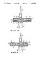
- FIG. 2is a cross sectional top view of the valve housing wherein the piston is shown in a central sealed position;
- FIG. 3is a cross sectional view of the present invention wherein the piston is shown in an open irrigation position
- FIG. 4is a cross sectional view of the present invention wherein the piston is shown in an open vacuum position
- FIG. 5is an external side cross sectional view of the present invention wherein an integral side port attachment is shown.
- FIG. 1shows the device of the invention held within a human hand during operation.
- a valve housing 1which housing may be formed from any suitable inert material such as stainless steel.
- body 1is formed of a plastic material such as polyphthalate carbonate (such as Lexan PPC) and is therefore inexpensively manufactured and disposable. It will be appreciated that many parts of the invention can be formed from such materials, i.e. stainless steel or plastic, or other materials, the choice depending on the cost of manufacture and the intended market. If the product is intended to be reusable the material must be sufficiently stable to be routinely subjected to sterilizing conditions, for example in an autoclave. On the other hand, disposable products need only meet the requirement that they be stable and inert with respect to the conditions under which they will be used.
- FIGS. 2-4show valve housing 1 having a cylindrical cavity 2 extending longitudinally through the housing from a first end 3 to the second end 4.
- a piston 5is positioned within the passage 2.
- piston 5may be constructed of a metal or plastic, and in the preferred case will be polyphthalate carbonate, i.e. Lexan PPC.
- Piston 5is configured with four circular flanges 6-9 located at the center of the piston.
- Piston 5is further configured with four additional flanges 10-13, i.e. two each located at each end of the piston 5.
- "O" rings 14-18are placed between the flanges in use.
- "O" rings 14-18are made from any suitable material which will provide a satisfactory seal along the inner surface of cavity 2.
- buttons 25 and 26are positioned on the end most portions of piston 5, separately numbered 19 and 20 in FIG. 2.
- Locking interfaces 21 and 22are formed on end most portions 19 and 20 respectively such that buttons 25 and 26 can snap fit on either end of the piston.
- Flanged sleeve stops 23 and 24, constructed of either plastic or stainless steel, as well as compression springs 27 and 28are positioned before buttons 25 and 26 are snapped into position.
- springs 27 and 28are double action equalizing springs of stainless steel, which may be obtained for example from the Smalley company of Ill. Such springs provide for an especially smooth feel when buttons 25 and 26 are pressed in use, and therefore provide a better tool for the practitioner.
- Springs 27 and 28are respectively set against the flanged sleeve stops 23 and 24. Those skilled in the art will appreciate that other means for biasing the piston in the manner obtained by using springs 27 and 28 could be used, again depending on the requirements for a given application, i.e. disposable or reusable.
- FIGS. 2-4show inlet tubes 29 and 30 located at openings on one side of the housing 1.
- Tube 31is located at an opening on the opposite side of the housing, the opening being longitudinally located between the opening for tubes 29 and 30.
- these openingscould be positioned in a number of orientations other than that shown in this preferred embodiment, limited only by the need to ensure that there are at least two inlet ports and one outlet port, and that the configuration of the openings allows for alternative communication between either of the tubes acting as an inlet with the tube acting as an outlet.
- the arrangementmust not allow direct communication between the two inlet ports regardless of the piston position within the communication passage.
- Probe 32is shown inserted into tube 31. In the preferred embodiment probe 32 is held in place by an epoxy seal, indicated at 34. Alternatively, an internal push-in snap ring may be used. An "O" ring seal 35 is shown where the base of probe 32 rests against housing 1. Supply tubing 36 is shown placed over hollow tube 29 and is configured to be attached to an irrigation line. Supply tubing 37 is shown placed over hollow tube 30 and is configured to be attached to a vacuum line.
- FIG. 1shows the preferred embodiment of the invention in a neutral or central shut-off position.
- Piston 5is in a "rest” position, situated so that the central flanges 6-9 and the "O" rings held therein seal-off outlet hole 38 from communication with cavity 2.
- Valve portions 39 and 40are formed on the piston on each side of the central seal formed by flanges 6-9. Outer seals are formed by flanges 10-13 and "O" rings 14 and 18.
- FIG. 3shows the preferred embodiment of the invention in the open-irrigation position.
- the practitionerwhen desiring an irrigation flow, depresses button 25 (arrow) transmitting longitudinal motion to piston 5 in the direction of the second end 4, thereby compressing spring 27.
- Valve portion 39(FIG. 2) moves in the direction of the second end 4 until it allows irrigation fluid to flow from tube 29 into probe 32.
- button 25When the practitioner releases button 25, the stored energy in the compressed spring 27 forces piston 5 back towards first end 3.
- the piston's motionis interrupted upon contact with flange sleeve 23 or flange sleeve 24 or both to reach the intermediate shut-off position illustrated in FIG. 2.
- FIG. 4shows the preferred embodiment of the invention in the open-vacuum position.
- the practitionermay alternately desire a suction force.
- the practitionerwould depress button 26 (arrow), transmitting longitudinal motion to piston 5 in the direction of first end 3, compressing spring 28.
- Valve portion 40(FIG. 2) moves in the direction of the first end 3 until it allows a suction force to flow through probe 32.
- the stored energy in compressed spring 28forces piston 5 back towards second end 4.
- the piston's motionis interrupted upon contact with flange sleeve 24 or flange sleeve 23 or both to reach the intermediate shut-off position as illustrated in FIG. 2.
- FIG. 5shows an additional preferred embodiment of the invention which includes a side port configured to allow access of a flexible instrument through the valve body without interrupting the function of the suction irrigation device.
- the valve body housingis shaped to form a side port 45 containing a narrow passage 46.
- a rubber dam seal 47is placed over the outerpost portion of passage 46.
- a flexible instrumentsuch as a fiber optic bundle 49 is inserted through seal 47, continuing through the side port 45 and into hollow tube 31, finally extending into the hollow probe 32.
- a standard one-way medical on-off valve stopcock 48available from the Malenkrodt company, is shown permanently bonded to the side port 45, using an acrylic adhesive or solvent bonding technology. Valve 48 is turned off to prevent fluids from flowing through the narrow passage 46 when side port 45 is not being used to hold a flexible instrument.
- the suction irrigation device of the present inventionaffords the practitioner substantial advantages over those devices of prior art.
- the inventionallows for the practitioner to operate the suction irrigation device with one hand.
- the deviceWhen not in use the device is designed to automatically return to a central fully sealed position. No by-pass of irrigation solution directly to the vacuum line is possible.
- buttons 25 and 26might be varied to provide the practitioner with improved grip, or to color code the vacuum and irrigation functions.
- the single pistoncould also be positioned from one side, by pushing and pulling the piston from that side rather than utilizing the to and fro action of the preferred embodiment.
- the spring loaded self centering feature of the inventionis considered advantageous, it would also be possible to utilize such to and fro action, but have the piston rest in any of the three desired postions, i.e. vacuum open/irrigation closed, fully closed, or irrigation open/vacuum closed. We believe, however, that the embodiment shown in the figures provides the greatest ease of use.
Landscapes
- Health & Medical Sciences (AREA)
- Engineering & Computer Science (AREA)
- Heart & Thoracic Surgery (AREA)
- General Engineering & Computer Science (AREA)
- Veterinary Medicine (AREA)
- Anesthesiology (AREA)
- Biomedical Technology (AREA)
- Hematology (AREA)
- Life Sciences & Earth Sciences (AREA)
- Animal Behavior & Ethology (AREA)
- General Health & Medical Sciences (AREA)
- Public Health (AREA)
- Vascular Medicine (AREA)
- Pulmonology (AREA)
- Mechanical Engineering (AREA)
- External Artificial Organs (AREA)
- Endoscopes (AREA)
- Mechanically-Actuated Valves (AREA)
- Multiple-Way Valves (AREA)
- Infusion, Injection, And Reservoir Apparatuses (AREA)
- Catching Or Destruction (AREA)
- Medical Preparation Storing Or Oral Administration Devices (AREA)
- Devices For Medical Bathing And Washing (AREA)
- Media Introduction/Drainage Providing Device (AREA)
Abstract
Description
Claims (5)
Priority Applications (11)
| Application Number | Priority Date | Filing Date | Title |
|---|---|---|---|
| US07/640,242US5247966A (en) | 1991-01-11 | 1991-01-11 | Suction irrigator valve apparatus |
| IL100590AIL100590A0 (en) | 1991-01-11 | 1992-01-05 | Suction irrigator valve apparatus |
| ZA9289AZA9289B (en) | 1991-01-11 | 1992-01-07 | Suction irrigator valve apparatus |
| PCT/US1992/000142WO1992012369A1 (en) | 1991-01-11 | 1992-01-09 | Suction irrigator valve apparatus |
| JP4504479AJPH07102225B2 (en) | 1991-01-11 | 1992-01-09 | Suction cleaning valve device |
| KR1019930702096AKR930703563A (en) | 1991-01-11 | 1992-01-09 | Valve device for suction tube |
| AU11898/92AAU660010B2 (en) | 1991-01-11 | 1992-01-09 | Suction irrigator valve apparatus |
| CA002100264ACA2100264A1 (en) | 1991-01-11 | 1992-01-09 | Irrigator valve apparatus |
| EP92903790AEP0720710A1 (en) | 1991-01-11 | 1992-01-09 | Suction irrigator valve apparatus |
| CN92100961ACN1064815A (en) | 1991-01-11 | 1992-01-11 | Suction irrigator valve apparatus |
| TW081101366ATW197952B (en) | 1991-01-11 | 1992-04-17 |
Applications Claiming Priority (1)
| Application Number | Priority Date | Filing Date | Title |
|---|---|---|---|
| US07/640,242US5247966A (en) | 1991-01-11 | 1991-01-11 | Suction irrigator valve apparatus |
Publications (1)
| Publication Number | Publication Date |
|---|---|
| US5247966Atrue US5247966A (en) | 1993-09-28 |
Family
ID=24567427
Family Applications (1)
| Application Number | Title | Priority Date | Filing Date |
|---|---|---|---|
| US07/640,242Expired - Fee RelatedUS5247966A (en) | 1991-01-11 | 1991-01-11 | Suction irrigator valve apparatus |
Country Status (11)
| Country | Link |
|---|---|
| US (1) | US5247966A (en) |
| EP (1) | EP0720710A1 (en) |
| JP (1) | JPH07102225B2 (en) |
| KR (1) | KR930703563A (en) |
| CN (1) | CN1064815A (en) |
| AU (1) | AU660010B2 (en) |
| CA (1) | CA2100264A1 (en) |
| IL (1) | IL100590A0 (en) |
| TW (1) | TW197952B (en) |
| WO (1) | WO1992012369A1 (en) |
| ZA (1) | ZA9289B (en) |
Cited By (38)
| Publication number | Priority date | Publication date | Assignee | Title |
|---|---|---|---|---|
| US5447494A (en)* | 1990-01-26 | 1995-09-05 | American Hydro-Surgical Instruments, Inc. | Composite irrigation and suction probe |
| US5454792A (en)* | 1993-04-19 | 1995-10-03 | Hyproteck, Inc. | Linear slide valve for CVC access |
| US5466216A (en)* | 1994-04-11 | 1995-11-14 | Gish Biomedical, Inc. | Antegrade/retrograde cardioplegia method and system |
| US5490836A (en)* | 1991-10-18 | 1996-02-13 | Desai; Ashvin H. | Endoscopic surgical instrument |
| US5562640A (en)* | 1991-10-18 | 1996-10-08 | United States Surgical Corporation | Endoscopic surgical instrument for aspiration and irrigation |
| US5605537A (en)* | 1994-08-08 | 1997-02-25 | Ivey; Jack L. | Endoscopic device |
| US5620426A (en)* | 1992-04-07 | 1997-04-15 | Innovata Biomed Limited | Connecting device |
| US5755686A (en)* | 1995-01-30 | 1998-05-26 | Minnesota Mining And Manufacturing Company | Antegrade/retrograde switch for cardioplegia cannulae |
| US5861002A (en)* | 1991-10-18 | 1999-01-19 | Desai; Ashvin H. | Endoscopic surgical instrument |
| US5878773A (en)* | 1997-09-15 | 1999-03-09 | Essef Corporation | Auxiliary flow path valve |
| US5908403A (en)* | 1996-05-07 | 1999-06-01 | Cordis Europa, N.V. | Drainage catheter with hemostatic device |
| US5976129A (en)* | 1991-10-18 | 1999-11-02 | Desai; Ashvin H. | Endoscopic surgical instrument |
| US6231591B1 (en) | 1991-10-18 | 2001-05-15 | 2000 Injectx, Inc. | Method of localized fluid therapy |
| US20020188175A1 (en)* | 1999-04-30 | 2002-12-12 | Levine Andy H. | Medical suction valve |
| US20030073908A1 (en)* | 1996-04-26 | 2003-04-17 | 2000 Injectx, Inc. | Method and apparatus for delivery of genes, enzymes and biological agents to tissue cells |
| US20040002647A1 (en)* | 1991-10-18 | 2004-01-01 | Ashvin Desai | Gel injection treatment of body parts |
| US6730081B1 (en) | 1991-10-18 | 2004-05-04 | Ashvin H. Desai | Endoscopic surgical instrument |
| US20040127816A1 (en)* | 2002-12-30 | 2004-07-01 | Adriano Braun Galvao | Handheld blood collection device |
| US20040204679A1 (en)* | 1998-01-29 | 2004-10-14 | Allegiance Healthcare Corporation | Disposable surgical suction/irrigation trumpet valve tube cassette |
| US20050005634A1 (en)* | 2001-12-19 | 2005-01-13 | Bsh Bosch Und Siemens Hausegerate Gmbh | Multi-way valve and refrigerating machine with multi-way valve |
| US20050255039A1 (en)* | 1998-06-26 | 2005-11-17 | Pro Surg, Inc., A California Corporation | Gel injection treatment of breast, fibroids & endometrial ablation |
| US20050267417A1 (en)* | 2004-05-25 | 2005-12-01 | Secrest Dean J | Irrigating biopsy inlet valve |
| US20060135851A1 (en)* | 2004-11-30 | 2006-06-22 | Masayuki Yamazaki | Adapter unit for connecting cleaning fluid supply device to endoscopes |
| US20070282168A1 (en)* | 2006-04-10 | 2007-12-06 | Kaye Christopher J | Biopsy inlet valve |
| US20080027268A1 (en)* | 2004-04-05 | 2008-01-31 | Genesee Biomedical, Inc. | Method and Apparaus for the Surgical Treatment of Congestive Heart Failure |
| US7549424B2 (en) | 1991-10-18 | 2009-06-23 | Pro Surg, Inc. | Method and apparatus for tissue treatment with laser and electromagnetic radiation |
| US20100010310A1 (en)* | 2008-07-14 | 2010-01-14 | Ethicon Endo-Surgery, Inc. | Methods and devices for maintaining visibility and providing irrigation and/or suction during surgical procedures |
| US20130068331A1 (en)* | 2010-06-04 | 2013-03-21 | Carrier Commercial Refrigeration, Inc. | Soft-Serve Confection Valve |
| WO2013113948A1 (en)* | 2012-01-30 | 2013-08-08 | Ipsumpro, S.L. | Injection device including a controlled-flow needle |
| US8702596B2 (en) | 2010-09-17 | 2014-04-22 | United States Endoscopy Group, Inc. | Biopsy inlet valve improvements |
| US20140151280A1 (en)* | 2012-12-03 | 2014-06-05 | General Electric Company | Flow diverter device |
| US9161680B2 (en) | 2013-11-26 | 2015-10-20 | Bracco Diagnostics Inc. | Disposable air/water valve for an endoscopic device |
| US9248228B2 (en) | 2013-01-18 | 2016-02-02 | Peter L. Bono | Suction and irrigation apparatus with anti-clogging capability |
| US9937317B2 (en) | 2012-01-30 | 2018-04-10 | Ipsumpro, S.L. | Modified medical syringe with a flow regulator for the administration of local anaesthetic |
| US10220123B2 (en) | 2010-08-25 | 2019-03-05 | Camodo, Llc | Hand held irrigation and suction tool |
| US10253892B2 (en)* | 2017-02-09 | 2019-04-09 | Goodrich Corporation | Energetic one way sequence termination valve |
| US10286141B2 (en) | 2014-01-31 | 2019-05-14 | Camodo, Llc | Combination suction and irrigation tool |
| US20220323985A1 (en)* | 2019-10-07 | 2022-10-13 | Threebond Co., Ltd. | Dispensing apparatus, movable member, circulation control method |
Families Citing this family (13)
| Publication number | Priority date | Publication date | Assignee | Title |
|---|---|---|---|---|
| US20130096518A1 (en) | 2007-12-06 | 2013-04-18 | Smith & Nephew Plc | Wound filling apparatuses and methods |
| US11253399B2 (en) | 2007-12-06 | 2022-02-22 | Smith & Nephew Plc | Wound filling apparatuses and methods |
| GB0723876D0 (en) | 2007-12-06 | 2008-01-16 | Smith & Nephew | Apparatus and method for topical negative pressure therapy |
| CN101785703B (en)* | 2009-12-25 | 2011-08-31 | 联合微创医疗器械有限公司 | Suction Irrigator for Minimally Invasive Surgery |
| DE102010009816B4 (en)* | 2010-03-02 | 2016-11-24 | Manfred Völker | Fluid system for supplying a device with highly pure liquid |
| JP5399458B2 (en)* | 2011-10-27 | 2014-01-29 | 川澄化学工業株式会社 | Blood collection device and sliding flow path switching means |
| CN107929845B (en)* | 2017-11-29 | 2024-02-23 | 苏州佳洲医疗器械有限公司 | Surgical simultaneous-suction and simultaneous-suction set |
| CN108150674A (en)* | 2017-12-31 | 2018-06-12 | 上饶市圣麦司洁具制造有限公司 | It is a kind of to plug into and the water nozzle component in switching water discharging direction |
| CN111765269B (en)* | 2019-04-01 | 2021-08-24 | 浙江盾安禾田金属有限公司 | Switching valve and refrigerating system with same |
| CN109908424A (en)* | 2019-04-10 | 2019-06-21 | 苏州中科先进技术研究院有限公司 | A kind of disposable flushing aspirator |
| KR102362472B1 (en)* | 2020-02-24 | 2022-02-15 | 주식회사 오렌지메딕스 | Suction and irrigation device |
| CN112386393B (en)* | 2020-12-01 | 2024-08-09 | 安徽医科大学第四附属医院 | Bionic anus defecation control device based on intelligent electromagnetic valve |
| CN113274563B (en)* | 2021-04-25 | 2024-04-16 | 深圳市先健呼吸科技有限公司 | Lavage catheter and lavage catheter system |
Citations (12)
| Publication number | Priority date | Publication date | Assignee | Title |
|---|---|---|---|---|
| US2633324A (en)* | 1948-04-27 | 1953-03-31 | Daniel H Bierman | Manual multiway valve |
| US2912007A (en)* | 1953-04-15 | 1959-11-10 | Johnson Clarence | Pilot operated four-way valve |
| US3678959A (en)* | 1970-07-30 | 1972-07-25 | Richard B Liposky | Hand operable selector valve |
| US3722800A (en)* | 1969-05-28 | 1973-03-27 | Melard Mfg Corp | Shuttle type diverter valve for use with handle controlled spray |
| US3771565A (en)* | 1972-11-06 | 1973-11-13 | Skinner Precision Ind Inc | Fluidic directional control valve assembly |
| US3870045A (en)* | 1971-07-08 | 1975-03-11 | Curtis M Vaughan | Multipurpose hygienic kit |
| US3951166A (en)* | 1974-06-12 | 1976-04-20 | Whitener Robert V | Rapid acting valve assembly |
| US3993099A (en)* | 1974-06-25 | 1976-11-23 | Imperial Chemical Industries Limited | Plug valves |
| DE2824720A1 (en)* | 1978-06-06 | 1979-12-13 | Werner & Pfleiderer | Control valve for pressurised water - has sleeve in housing bore which forms annular channels and piston with separate chambers |
| US4502508A (en)* | 1982-03-29 | 1985-03-05 | Smiths Industries Public Limited Company | Spool valve for connecting an output to one of two inputs |
| US4668215A (en)* | 1986-05-15 | 1987-05-26 | Dexide, Inc. | Irrigator-evacuator control for surgical procedures |
| US4881523A (en)* | 1988-02-04 | 1989-11-21 | Richard Wolf Gmbh | Endoscope |
Family Cites Families (1)
| Publication number | Priority date | Publication date | Assignee | Title |
|---|---|---|---|---|
| AU458487B2 (en)* | 1972-05-15 | 1975-02-27 | Liposky, Richard B. | Rand operable selector valve |
- 1991
- 1991-01-11USUS07/640,242patent/US5247966A/ennot_activeExpired - Fee Related
- 1992
- 1992-01-05ILIL100590Apatent/IL100590A0/enactiveIP Right Grant
- 1992-01-07ZAZA9289Apatent/ZA9289B/enunknown
- 1992-01-09KRKR1019930702096Apatent/KR930703563A/ennot_activeCeased
- 1992-01-09JPJP4504479Apatent/JPH07102225B2/ennot_activeExpired - Lifetime
- 1992-01-09CACA002100264Apatent/CA2100264A1/ennot_activeAbandoned
- 1992-01-09AUAU11898/92Apatent/AU660010B2/ennot_activeCeased
- 1992-01-09WOPCT/US1992/000142patent/WO1992012369A1/ennot_activeApplication Discontinuation
- 1992-01-09EPEP92903790Apatent/EP0720710A1/ennot_activeWithdrawn
- 1992-01-11CNCN92100961Apatent/CN1064815A/enactivePending
- 1992-04-17TWTW081101366Apatent/TW197952B/zhactive
Patent Citations (12)
| Publication number | Priority date | Publication date | Assignee | Title |
|---|---|---|---|---|
| US2633324A (en)* | 1948-04-27 | 1953-03-31 | Daniel H Bierman | Manual multiway valve |
| US2912007A (en)* | 1953-04-15 | 1959-11-10 | Johnson Clarence | Pilot operated four-way valve |
| US3722800A (en)* | 1969-05-28 | 1973-03-27 | Melard Mfg Corp | Shuttle type diverter valve for use with handle controlled spray |
| US3678959A (en)* | 1970-07-30 | 1972-07-25 | Richard B Liposky | Hand operable selector valve |
| US3870045A (en)* | 1971-07-08 | 1975-03-11 | Curtis M Vaughan | Multipurpose hygienic kit |
| US3771565A (en)* | 1972-11-06 | 1973-11-13 | Skinner Precision Ind Inc | Fluidic directional control valve assembly |
| US3951166A (en)* | 1974-06-12 | 1976-04-20 | Whitener Robert V | Rapid acting valve assembly |
| US3993099A (en)* | 1974-06-25 | 1976-11-23 | Imperial Chemical Industries Limited | Plug valves |
| DE2824720A1 (en)* | 1978-06-06 | 1979-12-13 | Werner & Pfleiderer | Control valve for pressurised water - has sleeve in housing bore which forms annular channels and piston with separate chambers |
| US4502508A (en)* | 1982-03-29 | 1985-03-05 | Smiths Industries Public Limited Company | Spool valve for connecting an output to one of two inputs |
| US4668215A (en)* | 1986-05-15 | 1987-05-26 | Dexide, Inc. | Irrigator-evacuator control for surgical procedures |
| US4881523A (en)* | 1988-02-04 | 1989-11-21 | Richard Wolf Gmbh | Endoscope |
Non-Patent Citations (5)
| Title |
|---|
| Apple Medical Corporation, Brochure entitled "Laparoscopic cholecystectomy". |
| Apple Medical Corporation, Brochure entitled Laparoscopic cholecystectomy .* |
| Cabot Medical Brochure entitled "Introducing the Corson Disposable Suction/Irrigation Probe" Apr. 1990. |
| Cabot Medical Brochure entitled Introducing the Corson Disposable Suction/Irrigation Probe Apr. 1990.* |
| Karl Storz Endoscopy Brochure.* |
Cited By (53)
| Publication number | Priority date | Publication date | Assignee | Title |
|---|---|---|---|---|
| US5447494A (en)* | 1990-01-26 | 1995-09-05 | American Hydro-Surgical Instruments, Inc. | Composite irrigation and suction probe |
| US5607391A (en)* | 1991-10-18 | 1997-03-04 | United States Surgical Corporation | Endoscopic surgical instrument for aspiration and irrigation |
| US6231591B1 (en) | 1991-10-18 | 2001-05-15 | 2000 Injectx, Inc. | Method of localized fluid therapy |
| US5490836A (en)* | 1991-10-18 | 1996-02-13 | Desai; Ashvin H. | Endoscopic surgical instrument |
| US5562640A (en)* | 1991-10-18 | 1996-10-08 | United States Surgical Corporation | Endoscopic surgical instrument for aspiration and irrigation |
| US20040002647A1 (en)* | 1991-10-18 | 2004-01-01 | Ashvin Desai | Gel injection treatment of body parts |
| US6730081B1 (en) | 1991-10-18 | 2004-05-04 | Ashvin H. Desai | Endoscopic surgical instrument |
| US5861002A (en)* | 1991-10-18 | 1999-01-19 | Desai; Ashvin H. | Endoscopic surgical instrument |
| US7549424B2 (en) | 1991-10-18 | 2009-06-23 | Pro Surg, Inc. | Method and apparatus for tissue treatment with laser and electromagnetic radiation |
| US5976129A (en)* | 1991-10-18 | 1999-11-02 | Desai; Ashvin H. | Endoscopic surgical instrument |
| US5620426A (en)* | 1992-04-07 | 1997-04-15 | Innovata Biomed Limited | Connecting device |
| US5454792A (en)* | 1993-04-19 | 1995-10-03 | Hyproteck, Inc. | Linear slide valve for CVC access |
| US5466216A (en)* | 1994-04-11 | 1995-11-14 | Gish Biomedical, Inc. | Antegrade/retrograde cardioplegia method and system |
| US5605537A (en)* | 1994-08-08 | 1997-02-25 | Ivey; Jack L. | Endoscopic device |
| US5755686A (en)* | 1995-01-30 | 1998-05-26 | Minnesota Mining And Manufacturing Company | Antegrade/retrograde switch for cardioplegia cannulae |
| US20030073908A1 (en)* | 1996-04-26 | 2003-04-17 | 2000 Injectx, Inc. | Method and apparatus for delivery of genes, enzymes and biological agents to tissue cells |
| US5908403A (en)* | 1996-05-07 | 1999-06-01 | Cordis Europa, N.V. | Drainage catheter with hemostatic device |
| US5878773A (en)* | 1997-09-15 | 1999-03-09 | Essef Corporation | Auxiliary flow path valve |
| US20070142775A1 (en)* | 1998-01-29 | 2007-06-21 | Peter Visconti | Disposable surgical suction/irrigation trumpet valve tube cassette |
| US8795232B2 (en) | 1998-01-29 | 2014-08-05 | Allegiance Corporation | Disposable surgical suction/irrigation trumpet valve tube cassette |
| US7776014B2 (en) | 1998-01-29 | 2010-08-17 | Peter Visconti | Disposable surgical suction/irrigation trumpet valve tube cassette |
| US20040204679A1 (en)* | 1998-01-29 | 2004-10-14 | Allegiance Healthcare Corporation | Disposable surgical suction/irrigation trumpet valve tube cassette |
| US20050255039A1 (en)* | 1998-06-26 | 2005-11-17 | Pro Surg, Inc., A California Corporation | Gel injection treatment of breast, fibroids & endometrial ablation |
| US7318814B2 (en)* | 1999-04-30 | 2008-01-15 | Boston Scientific Scimed, Inc. | Medical suction valve |
| US20020188175A1 (en)* | 1999-04-30 | 2002-12-12 | Levine Andy H. | Medical suction valve |
| US7093462B2 (en)* | 2001-12-19 | 2006-08-22 | Bsh Bosch Und Siemens Hausgeraete Gmbh | Multi-way valve and refrigerating machine with multi-way valve |
| US20050005634A1 (en)* | 2001-12-19 | 2005-01-13 | Bsh Bosch Und Siemens Hausegerate Gmbh | Multi-way valve and refrigerating machine with multi-way valve |
| US20040127816A1 (en)* | 2002-12-30 | 2004-07-01 | Adriano Braun Galvao | Handheld blood collection device |
| US20080027268A1 (en)* | 2004-04-05 | 2008-01-31 | Genesee Biomedical, Inc. | Method and Apparaus for the Surgical Treatment of Congestive Heart Failure |
| US20050267417A1 (en)* | 2004-05-25 | 2005-12-01 | Secrest Dean J | Irrigating biopsy inlet valve |
| US20100240956A1 (en)* | 2004-05-25 | 2010-09-23 | Secrest Dean J | Irrigating biopsy inlet valve |
| US7901350B2 (en)* | 2004-11-30 | 2011-03-08 | Fujinon Corporation | Adapter unit for connecting cleaning fluid supply device to endoscopes |
| US20060135851A1 (en)* | 2004-11-30 | 2006-06-22 | Masayuki Yamazaki | Adapter unit for connecting cleaning fluid supply device to endoscopes |
| US20070282168A1 (en)* | 2006-04-10 | 2007-12-06 | Kaye Christopher J | Biopsy inlet valve |
| US7967744B2 (en) | 2006-04-10 | 2011-06-28 | U.S. Endoscopy Group, Inc. | Biopsy inlet valve |
| US20100010310A1 (en)* | 2008-07-14 | 2010-01-14 | Ethicon Endo-Surgery, Inc. | Methods and devices for maintaining visibility and providing irrigation and/or suction during surgical procedures |
| US8915842B2 (en) | 2008-07-14 | 2014-12-23 | Ethicon Endo-Surgery, Inc. | Methods and devices for maintaining visibility and providing irrigation and/or suction during surgical procedures |
| US9903495B2 (en)* | 2010-06-04 | 2018-02-27 | Carrier Commerical Refrigeration, Inc. | Soft-serve confection valve |
| US20130068331A1 (en)* | 2010-06-04 | 2013-03-21 | Carrier Commercial Refrigeration, Inc. | Soft-Serve Confection Valve |
| US10220123B2 (en) | 2010-08-25 | 2019-03-05 | Camodo, Llc | Hand held irrigation and suction tool |
| US8702596B2 (en) | 2010-09-17 | 2014-04-22 | United States Endoscopy Group, Inc. | Biopsy inlet valve improvements |
| US9364607B2 (en) | 2012-01-30 | 2016-06-14 | Ipsumpro, S.L. | Injection device including a controlled-flow needle |
| US9937317B2 (en) | 2012-01-30 | 2018-04-10 | Ipsumpro, S.L. | Modified medical syringe with a flow regulator for the administration of local anaesthetic |
| WO2013113948A1 (en)* | 2012-01-30 | 2013-08-08 | Ipsumpro, S.L. | Injection device including a controlled-flow needle |
| US9328485B2 (en)* | 2012-12-03 | 2016-05-03 | General Electric Company | Flow diverter device |
| US20140151280A1 (en)* | 2012-12-03 | 2014-06-05 | General Electric Company | Flow diverter device |
| US9248228B2 (en) | 2013-01-18 | 2016-02-02 | Peter L. Bono | Suction and irrigation apparatus with anti-clogging capability |
| US10245359B2 (en) | 2013-01-18 | 2019-04-02 | Peter L. Bono | Suction and irrigation apparatus with anti-clogging capability |
| US9161680B2 (en) | 2013-11-26 | 2015-10-20 | Bracco Diagnostics Inc. | Disposable air/water valve for an endoscopic device |
| US10286141B2 (en) | 2014-01-31 | 2019-05-14 | Camodo, Llc | Combination suction and irrigation tool |
| US10253892B2 (en)* | 2017-02-09 | 2019-04-09 | Goodrich Corporation | Energetic one way sequence termination valve |
| US10385981B2 (en) | 2017-02-09 | 2019-08-20 | Goodrich Corporation | Energetic one way sequence termination valve |
| US20220323985A1 (en)* | 2019-10-07 | 2022-10-13 | Threebond Co., Ltd. | Dispensing apparatus, movable member, circulation control method |
Also Published As
| Publication number | Publication date |
|---|---|
| CA2100264A1 (en) | 1992-07-12 |
| AU660010B2 (en) | 1995-06-08 |
| JPH06503495A (en) | 1994-04-21 |
| ZA9289B (en) | 1993-10-07 |
| KR930703563A (en) | 1993-11-30 |
| WO1992012369A1 (en) | 1992-07-23 |
| EP0720710A1 (en) | 1996-07-10 |
| IL100590A0 (en) | 1992-09-06 |
| EP0720710A4 (en) | 1994-06-13 |
| AU1189892A (en) | 1992-08-17 |
| TW197952B (en) | 1993-01-11 |
| JPH07102225B2 (en) | 1995-11-08 |
| CN1064815A (en) | 1992-09-30 |
Similar Documents
| Publication | Publication Date | Title |
|---|---|---|
| US5247966A (en) | Suction irrigator valve apparatus | |
| CA2011154C (en) | Medical evacuation and irrigation device | |
| US7361164B2 (en) | Multi-outlet medical dispensing device | |
| US6364853B1 (en) | Irrigation and suction valve and method therefor | |
| US4881523A (en) | Endoscope | |
| US4776840A (en) | Hand-held medical evacuator and irrigation device | |
| US5282790A (en) | Cannula sealing mechanism | |
| US5449145A (en) | Valve device for controlling flows in surgical applications | |
| US5306237A (en) | Disposable lavage | |
| AU2011336623B2 (en) | Disposable air/water valve for an endoscope | |
| US4680026A (en) | Suction-irrigation equipment having a reciprocating valve | |
| US5505710A (en) | Telescoping probe | |
| US3830225A (en) | Multiple purpose stopcock arrangement for suctioning, injection, oxygen cessory equipment | |
| US5427144A (en) | Valve means with fluid retraction means | |
| US5490836A (en) | Endoscopic surgical instrument | |
| US5100377A (en) | Medical evacuation and irrigation device | |
| EP0365300A2 (en) | Sterilisable syringe | |
| JPH08508658A (en) | Irrigation control valve for endoscopic equipment | |
| JPH0343892B2 (en) | ||
| US5813402A (en) | Valve for pulmonary catheter | |
| US20230321421A1 (en) | Hemostasis valve device | |
| GB2146098A (en) | Valve system for medical and veterinary appliances | |
| CN223323822U (en) | Surgical irrigation, suction and drainage components | |
| CN211797898U (en) | Medical waste liquid suction tube | |
| JPH0420613B2 (en) |
Legal Events
| Date | Code | Title | Description |
|---|---|---|---|
| AS | Assignment | Owner name:TAHOE PRO INSTRUMENTS, A PARTNERSHIP Free format text:ASSIGNMENT OF ASSIGNORS INTEREST.;ASSIGNOR:STEVENS, JON A.;REEL/FRAME:005586/0001 Effective date:19910108 | |
| AS | Assignment | Owner name:TAHOE SURGICAL INSTRUMENTS, INC. A CORP. OF NEV Free format text:ASSIGNMENT OF ASSIGNORS INTEREST.;ASSIGNOR:TAHOE PRO INSTRUMENTS, INC.;REEL/FRAME:006162/0385 Effective date:19920616 | |
| AS | Assignment | Owner name:TSI INVESTMENT COMPANY, INC., NEVADA Free format text:ASSIGNMENT OF ASSIGNORS INTEREST.;ASSIGNOR:TAHOE SURGICAL INSTRUMENTS, INC. A CORP. OF NV;REEL/FRAME:006188/0202 Effective date:19920628 | |
| AS | Assignment | Owner name:TAHOE SURGICAL INSTRUMENTS, INC., NEVADA Free format text:ASSIGNMENT OF ASSIGNORS INTEREST;ASSIGNOR:TSI INVESTMENT COMPANY, INC.;REEL/FRAME:006604/0443 Effective date:19930625 | |
| AS | Assignment | Owner name:TAHOE SURGICAL INSTRUMENTS - PUERTO RICO, INC. Free format text:ASSIGNMENT OF ASSIGNORS INTEREST;ASSIGNOR:HILL, ROGER R.;REEL/FRAME:006650/0203 Effective date:19930701 Owner name:TAHOE SURGICAL INSTRUMENTS - PUERTO RICO, INC., PU Free format text:ASSIGNMENT OF ASSIGNORS INTEREST;ASSIGNOR:TAHOE SURGICAL INSTRUMENTS, INC.;REEL/FRAME:006650/0200 Effective date:19930804 | |
| REMI | Maintenance fee reminder mailed | ||
| LAPS | Lapse for failure to pay maintenance fees | ||
| FP | Lapsed due to failure to pay maintenance fee | Effective date:19971001 | |
| STCH | Information on status: patent discontinuation | Free format text:PATENT EXPIRED DUE TO NONPAYMENT OF MAINTENANCE FEES UNDER 37 CFR 1.362 |