US5247795A - Scroll expander driven compressor assembly - Google Patents
Scroll expander driven compressor assemblyDownload PDFInfo
- Publication number
- US5247795A US5247795AUS07/861,574US86157492AUS5247795AUS 5247795 AUS5247795 AUS 5247795AUS 86157492 AUS86157492 AUS 86157492AUS 5247795 AUS5247795 AUS 5247795A
- Authority
- US
- United States
- Prior art keywords
- expander
- wrap
- compressor
- scroll
- support means
- Prior art date
- Legal status (The legal status is an assumption and is not a legal conclusion. Google has not performed a legal analysis and makes no representation as to the accuracy of the status listed.)
- Expired - Fee Related
Links
Images


Classifications
- F—MECHANICAL ENGINEERING; LIGHTING; HEATING; WEAPONS; BLASTING
- F01—MACHINES OR ENGINES IN GENERAL; ENGINE PLANTS IN GENERAL; STEAM ENGINES
- F01C—ROTARY-PISTON OR OSCILLATING-PISTON MACHINES OR ENGINES
- F01C11/00—Combinations of two or more machines or engines, each being of rotary-piston or oscillating-piston type
- F01C11/002—Combinations of two or more machines or engines, each being of rotary-piston or oscillating-piston type of similar working principle
- F01C11/004—Combinations of two or more machines or engines, each being of rotary-piston or oscillating-piston type of similar working principle and of complementary function, e.g. internal combustion engine with supercharger
- F—MECHANICAL ENGINEERING; LIGHTING; HEATING; WEAPONS; BLASTING
- F01—MACHINES OR ENGINES IN GENERAL; ENGINE PLANTS IN GENERAL; STEAM ENGINES
- F01C—ROTARY-PISTON OR OSCILLATING-PISTON MACHINES OR ENGINES
- F01C1/00—Rotary-piston machines or engines
- F01C1/02—Rotary-piston machines or engines of arcuate-engagement type, i.e. with circular translatory movement of co-operating members, each member having the same number of teeth or tooth-equivalents
- F01C1/0207—Rotary-piston machines or engines of arcuate-engagement type, i.e. with circular translatory movement of co-operating members, each member having the same number of teeth or tooth-equivalents both members having co-operating elements in spiral form
- F01C1/0215—Rotary-piston machines or engines of arcuate-engagement type, i.e. with circular translatory movement of co-operating members, each member having the same number of teeth or tooth-equivalents both members having co-operating elements in spiral form where only one member is moving
- F01C1/0223—Rotary-piston machines or engines of arcuate-engagement type, i.e. with circular translatory movement of co-operating members, each member having the same number of teeth or tooth-equivalents both members having co-operating elements in spiral form where only one member is moving with symmetrical double wraps
Definitions
- the present inventionpertains to a scroll-type expander-compressor drive system having a scroll-type expander which is used to drive a scroll-type compressor or pump.
- the scroll-type expander driven compressor systemis particularly adaptable for use in combination with a combustor, such as an internal combustion engine, which produces exhaust gases for driving the scroll-type expander.
- the scroll-type expandermay then drive the scroll-type compressor which can be used to supply pressurized air to the combustor or to drive other systems.
- Such known expander-compressor drive systemshave been found to be extremely efficient due to the inherent operating nature of scroll fluid devices.
- the advantages of such drive arrangementshave not heretobefore been fully realized due to various deficiencies associated with the prior art systems.
- such prior art systemshave been rather bulky due to the manner in which the expander drives the compressor, the use of individual counterweights for the scrolls and the inclusion of separate synchronizers between the drive and driven scroll elements.
- the scroll fluid deviceswhen used in combination with a combustor, the scroll fluid devices are subject to a wide range of temperatures which tend to expand or contract the relatively rotating scroll elements which results in system vibrations, noise and efficiency losses.
- the present inventionpertains to a compact scroll-type expander-compressor drive system including a scroll-type expander and compressor each of which includes a fixed element and an orbital element.
- a drive mechanisminterconnects the orbital elements of the expander and compressor such that the orbital elements move in unison.
- the drive mechanismalso incorporates a single synchronizer and counterweight assembly for both the expander and compressor.
- both the expander and compressorcomprise dual or multi-stage scroll fluid devices having a central orbital element sandwiched between fixed scroll elements.
- at least one strutis interconnected between the fixed scroll elements to compensate for thermal expansion and/or contraction.
- the scroll-type expander in the present inventionWhen used in combination with a combustor, the scroll-type expander in the present invention is driven by the hot exhaust gases emanating from the combustor and the output of the compressor is connected to the air input of the combustor. As the expander is driven by the hot exhaust gases, the drive mechanism causes the orbital element of the compressor to move relative to its fixed elements in order to pump intake air into the combustor. In a preferred embodiment, a heat exchanger is also provided to transfer heat from the output of the expander in order to preheat the air inputted to the combustor from the compressor.
- FIG. 1is a schematic view of the scroll-type expander driven compressor system of the present invention in combination with a combustor arrangement;
- FIG. 2is a perspective view of the expander-compressor assembly
- FIG. 3is a cross-sectional view taken along line III--III of FIG. 2;
- FIG. 4is an exploded perspective view of the expander-compressor assembly according to the present invention with a portion of the outer housing not shown for clarity;
- FIG. 5is a front elevational view taken along line V--V of FIG. 4;
- FIG. 6is a front elevational view taken along lines VI--VI of FIG. 4;
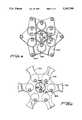
- FIG. 7depicts a spider structure incorporated in the expander-compressor assembly of the present invention.
- the scroll-type expander driven compressor system of the present inventionis generally indicated at 5 and includes an expander 10 which drives a compressor 15 through a drive mechanism shown at 20.
- a power takeoff shaft 25(hereinafter referred to as PTO) is also provided in the drive connection between expander 10 and compressor 15 and may be used to harness the auxiliarly power generated by expander 10 which is not needed to drive compressor 15.
- the scroll-type expander-compressor system of the present inventionis used in combination with a combustor 35 and a heat exchanger 40.
- the exhaust gas output from combustor 35flows through a pipe 50 to an input of expander 10 to cause rotation of drive mechanism 20 and compressor 15 in a manner which will be described in detail below.
- the exhaust gases from expander 10flow through duct 55 into heat exchanger 40 and are then exhausted.
- Driving of compressor 15causes air to be drawn into intake duct 60 and compressed by compressor 15.
- the compressed airis expelled from compressor 15 into output pipe 65 and into heat exchanger 40 wherein it is preheated by the radiant heat from exhaust duct 55.
- the intake airis then directed through a conduit 70 to be mixed with fuel from an input fuel line 75 to form a charge for combustor 35. If desired, compressed air for other applications can be supplied from compressor 15 via line 66.
- FIG. 2shows a perspective view of the expander driven compressor assembly according to a preferred embodiment of the invention.
- expander 10is located within an expander housing 85 and compressor 15 is located within a compressor housing 90.
- Expander housing 85 and compressor housing 90are joined by an interconnecting sleeve member 95.
- Sleeve number 95includes an integrally formed base portion 98 which can be used for fixedly mounting the expander driven compressor assembly.
- expander 10comprises a dual or multi-stage expander having a first fixed involute spiral wrap 100 secured to a side wall 105 of expander housing 85 and an axially spaced second fixed involute spiral wrap 115 secured to or integrally formed with a wrap support plate 120.
- Located between sidewall 105 and wrap support plate 120is an orbital scroll element including an elongated involute spiral wrap 125 and a wrap support assembly generally indicated at 130.
- Elongated involute spiral wrap 125extends substantially the entire distance between sidewall 105 and wrap support plate 120 such that involute spiral wrap 125 meshes with both involute spiral wrap 100 and involute spiral wrap 115.
- Wrap support assembly 130includes a plurality of radially extending plates (not individually labeled) which are interconnected at predetermined central locations between the flanges of involute spiral wrap 125. By this construction, a plurality of expansion chambers 160, 165 are defined between involute spiral wrap 125 and involute spiral wraps 100 and 115 respectively on either side of wrap support assembly 130.
- Wrap support assembly 130includes at least one central aperture 180 which fluidly interconnects exhaust pipe 50 with expansion chamber 165.
- the inlet from exhaust pipe 50 to expander 10includes a spider structure 190 (see FIG. 7).
- Spider structure 190may be integrally formed as part of sidewall 105 or may be fixedly secured within an inlet port formed in sidewall 105 or within exhaust pipe 50 adjacent the inlet area for expander 10.
- spider assembly 190includes various support ribs 200 defining fluid passageways 205 therebetween.
- Fixedly secured between a central structural support 210 for support ribs 200 and wrap support plate 120is at least one expansion strut 225 (see FIG. 3).
- expansion strut 225 for expander 10is of tubular construction and serves to compensate for thermal expansion and contraction of expander 10 as will be described more fully hereinafter.
- Compressor 15is constructed in a manner substantially identical to the construction of expander 10 as described above in that it includes a single orbital scroll element axially located between first and second fixed scroll elements.
- the first fixed scroll elementincludes a first fixed involute spiral wraps 250 integrally formed with or otherwise fixedly secured to sidewall 255 of compressor housing 90.
- the second fixed scroll elementincludes a fixed involute spiral wrap 260 axially extending from a wrap support plate 270.
- the orbital scroll elementincludes an elongated involute spiral wrap 275 and a wrap support assembly 280.
- Involute spiral wrap 275meshes with both involute spiral wraps 250 and 260.
- the flanges of involute spiral wrap 275are interconnected by wrap support assembly 280 which includes a substantially centrally and axially extending aperture 285 therein.
- involute spiral wrap 275orbits relative to fixed involute spiral wraps 250, 260, fluid is drawn into intake duct 60, is compressed within compression chambers 300, 305 defined on either side of wrap support assembly 280 and is exhaust through output pipe 65.
- spider structure 315is structurally identical to spider structure 190 described above with reference to FIG. 7.
- compressor 15includes an expansion strut 335 which extends between and is fixedly secured to spider structure 315 and wrap support plate 270. Again, expansion strut 335 is intended to compensate for axial expansion and contraction of compressor 15 as will be more fully discussed below.
- involute spiral wrap 275is permitted to orbit relative to involute spiral wraps 250 and 260 by means of a synchronizer which will be also detailed below.
- wrap support assembly 130 of expander 10is fixedly secured to an annular sleeve 400 which terminates in an inboard flange 405.
- Compressor 15includes a similar annular sleeve 415 which also terminates in an inboard flange 420.
- Flanges 405 and 420are interconnected by a plurality of drive posts 440 each having one end fixedly secured to flange 405 and a second, threaded end which extends through a respective aperture 450 in flange 420 and is secured thereto by a nut 460.
- wrap support assembly 130 of expander 10 and wrap support assembly 280 of compressor 15are thereby fixedly secured together through drive post 440, wrap support assemblies 130 and 280 move in unison in their orbital paths. Therefore, when expander 10 is driven by the exhaust gases of combustor 35, compressor 15 will also be driven through drive post 440 which collectively comprises drive mechanism 20. Additional features of the drive arrangement between expander 10 and compressor 15 will be more fully explained hereinafter along with a synchronizer system which enables the movable scroll elements to orbit relative to the fixed scroll elements in both expander 10 and compressor 15 without relative rotation.
- Expander housing 85which includes sidewall 105, is fixedly secured to compressor housing 90 through a housing sleeve member 490. As shown in FIGS. 3 and 4, both expander housing 85 and compressor housing 90 are fixedly secured to housing sleeve member 490 by means of a plurality of bolts 494 which extend through holes formed in flanges 496 and 498 of expander housing 85 and expander housing 90 respectively and through apertures 500 formed in housing sleeve member 490.
- bolts 494which extend through holes formed in flanges 496 and 498 of expander housing 85 and expander housing 90 respectively and through apertures 500 formed in housing sleeve member 490.
- Fixed wrap support plate 120 of second fixed involute spiral wrap 115includes a plurality of axially extending legs 510 which terminate in inwardly projecting tabs 520. Tabs 520 are fixedly secured by means of bolts 530 to a first bearing support member 540.
- Bearing support member 540is fixedly secured to sleeve member 490 through a plate or plates 545, spaced between consectitive drive posts 440, and is formed with a plurality of circumferentially spaced journal bearings 580.
- Freely rotatably mounted within journal bearings 580are a plurality of rollers 600. In the preferred embodiment six such rollers 600 are arranged in a hexagonal pattern located a predetermined radial distance inward from drive posts 440.
- wrap support plate 270 of fixed involute spiral wrap 260 of compressor 15includes a plurality of inwardly projecting legs 610 which terminate in a plurality of tabs 620. Tabs 620 are secured by means of bolts 630 to a second bearing support member 640.
- Bearing support member 640is fixedly secured to sleeve member 490 through a plate or plates 645, spaced between consecutive drive posts 440, and includes a plurality of journal bearings 680 which are axially spaced and opposed to journal bearings 580.
- rollers 600extend between and are rotatably mounted within both journal bearings 580 and 680.
- First bearing support member 540also includes a central journal bearing 700 which is axially spaced from a centrally located aperture 710 formed in second bearing support member 640.
- a drive shaft 725is freely rotatably mounted within central journal bearing 700 and extends through centrally located aperture 710.
- Drive shaft 725is used to drive an auxiliary output shaft 730 through a belt drive arrangement generally indicated at 735.
- Synchronizer and counterweight assembly 750includes a counterweight 760 having plurality of circumferentially spaced bores 770 aligned with journal bearings 580, 680.
- Counterweight 760is also formed with a pair of centrally located recesses 775 on either side of counterweight 760 and a through hole 780 located slightly, radially offset from a center point of counterweight 760.
- Through hole 780has a diameter greater than the diameter of drive shaft 725.
- Counterweight 760is also formed with a plurality of notches 790 formed about its outer periphery. The size of notches 790 is determined based on the desired size and weight of counterweight 760 as will be more fully discussed below.
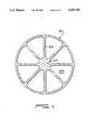
- FIG. 5depicts drive/synchronizer plate 800.
- Plate 800is provided with a plurality of bores 820 spaced about its periphery. Bores 820 correspond in number to the number of drive posts 440.
- plate 800Located radially inward of bores 820, plate 800 includes a plurality of bores 830 corresponding in number to the number of rollers 600.
- plate 800is formed with a central through hole 840.
- a pair of cams 850Located within recesses 775 of counterweight 760 is a pair of cams 850 having through holes 860 which are aligned with through hole 780.
- a similar cam 865 having a through hole 870is also provided in the central aperture 840 of each drive plate 800 and 810.
- Drive posts 440extend through bores 820 in plate 800, within notches 790 in counterweight 760, through the corresponding bores 820 in plate 810, and are then secured within apertures 450 of inboard flange 420 as previously described. In this manner, plates 800 and 810 are fixedly secured to orbit with involute spiral wrap 125 of expander 10 and involute spiral wrap 275 of compressor 15.
- each roller 600has a first end rotatably mounted within a respective journal bearing 580 of first bearing support member 540.
- Each roller 600extends from its respective journal bearing 580 through apertures 830 in plate 800, bores 770 in counterweight 760, through the respective apertures 830 in plate 810 and have their other end rotatably mounted within journal bearing 680 of second bearing support member 640.
- the radii of bores 770 and apertures 830are configured to equal the orbital radius of involute spiral wraps 125 and 275. Therefore, rollers 600 act on the inner surfaces of bores 770 and apertures 830 to support radial forces generated by the orbital movement of the orbital elements of expander 10 and compressor 15.
- This arrangementalso functions as a synchronizer which acts between the first and second fixed involute spiral wraps 100, 115 and orbiting involute spiral 125 of expander 10 and the first and second fixed involute spiral wraps 250, 260 and orbital involute spiral wrap 275 of compressor 15 to prevent relative rotation between these elements; i.e., the phase relationship between scroll elements is maintained.
- drive shaft 725is rotatably mounted within central journal bearing 700 at one end, is keyed to cams 850 and 865 at 880 and 885 respectively as shown in FIGS. 5 and 6 and has its second end rotatably mounted within centrally located aperture 710 of second bearing support member 640. From viewing FIG. 3, it becomes clearly evident that drive shaft 725 is retained axially by its connection to cams 850 and 865. From viewing FIGS. 5 and 6, it can be seen that as involute spiral wrap 125 of expander 10 orbits, plates 800 and 810 also orbit counter to counterweight 760. Of course, counterweight 760 orbits 180° out of phase with respect to the orbiting of plates 800 and 810.
- rollers 600are fixed in the radial direction by journal bearings 580 and 680 as plates 800 and 810 orbit counter to counterweight 760, the rollers 600 act on the surfaces of their respective bores 770, 830. Since drive shaft 725 is keyed to cams 850 and 865, drive shaft 725 will rotate as plates 800, 810 and counterweight 760 orbit. Any power developed by orbiting of expander 10 by the combustion gases flowing into the inlet pipe 50 and not used to orbit compressor 15 may be taken off auxiliary drive shaft 730 by means of its interconnection with drive shaft 725 through drive transfer assembly 735.
- drive transfer assembly 735comprises a belt drive system which cooperates with a pair of pulleys (not shown) respectively mounted on drive shaft 725 and auxiliary drive shaft 730, but a gear or a combination gear and chain transfer arrangement may also be utilized without departing from the spirit or scope of the present invention.
- expander 10is formed from steel and compressor 15 is formed from aluminum. The difference in radial forces developed during operation of expander 10 and compressor 15 is counteracted by counterweight 760. Notches 790 are sized to adjust the required counteracting or balancing mass.
- the exhaust gases entering expander 10may be in the range of approximately 1100° F. Extreme temperature environments such as this results in thermal expansion between the orbital and fixed elements of the expander 10 and to a lesser degree in the compressor 15.
- expansion struts 225 and 355are provided. Each expansion strut is formed from the same material as the component in which it is used.
- strut 225 in expander 100comprises a hollow steel rod. If temperature changes cause involute spiral wraps 100, 115 and 125 to expand or contract, strut 225 will expand or contract accordingly. Since the ends of wrap support plates 105, 120 are fixed to or form part of housing 85, strut 225 extends between only the middle portions of these plates which are inherently somewhat flexible.
Landscapes
- Engineering & Computer Science (AREA)
- Mechanical Engineering (AREA)
- General Engineering & Computer Science (AREA)
- Chemical & Material Sciences (AREA)
- Combustion & Propulsion (AREA)
- Rotary Pumps (AREA)
- Applications Or Details Of Rotary Compressors (AREA)
- Supercharger (AREA)
Abstract
Description
Claims (30)
Priority Applications (7)
| Application Number | Priority Date | Filing Date | Title |
|---|---|---|---|
| US07/861,574US5247795A (en) | 1992-04-01 | 1992-04-01 | Scroll expander driven compressor assembly |
| PCT/US1993/002598WO1993020342A1 (en) | 1992-04-01 | 1993-03-30 | Scroll expander driven compressor assembly |
| CA002133317ACA2133317A1 (en) | 1992-04-01 | 1993-03-30 | Scroll expander driven compressor assembly |
| EP93908461AEP0633979B1 (en) | 1992-04-01 | 1993-03-30 | Scroll expander driven compressor assembly |
| EP98200389AEP0846843A1 (en) | 1992-04-01 | 1993-03-30 | Scroll expander driven compressor assembly |
| JP5516885AJPH07505458A (en) | 1992-04-01 | 1993-03-30 | Spiral expander driven compressor assembly |
| DE69320798TDE69320798T2 (en) | 1992-04-01 | 1993-03-30 | SPIRAL COMPRESSOR |
Applications Claiming Priority (1)
| Application Number | Priority Date | Filing Date | Title |
|---|---|---|---|
| US07/861,574US5247795A (en) | 1992-04-01 | 1992-04-01 | Scroll expander driven compressor assembly |
Publications (1)
| Publication Number | Publication Date |
|---|---|
| US5247795Atrue US5247795A (en) | 1993-09-28 |
Family
ID=25336171
Family Applications (1)
| Application Number | Title | Priority Date | Filing Date |
|---|---|---|---|
| US07/861,574Expired - Fee RelatedUS5247795A (en) | 1992-04-01 | 1992-04-01 | Scroll expander driven compressor assembly |
Country Status (6)
| Country | Link |
|---|---|
| US (1) | US5247795A (en) |
| EP (2) | EP0846843A1 (en) |
| JP (1) | JPH07505458A (en) |
| CA (1) | CA2133317A1 (en) |
| DE (1) | DE69320798T2 (en) |
| WO (1) | WO1993020342A1 (en) |
Cited By (22)
| Publication number | Priority date | Publication date | Assignee | Title |
|---|---|---|---|---|
| US20010041280A1 (en)* | 1999-12-17 | 2001-11-15 | Hidefumi Mori | Air supply system for fuel cell |
| US6338912B1 (en)* | 1998-11-18 | 2002-01-15 | Kabushiki Kaisha Toyoda Jidoshokki Seisakusho | Fuel cell system having common scroll type compressor and regenerator |
| US6658866B2 (en)* | 2002-02-13 | 2003-12-09 | Carrier Corporation | Scroll expressor |
| US6758659B2 (en) | 2002-04-11 | 2004-07-06 | Shimao Ni | Scroll type fluid displacement apparatus with fully compliant floating scrolls |
| US20050126837A1 (en)* | 2003-12-11 | 2005-06-16 | Taxon Morse N. | Pressurized fuel vehicle having fuel system with an air motor |
| US20060130495A1 (en)* | 2004-07-13 | 2006-06-22 | Dieckmann John T | System and method of refrigeration |
| US20070172373A1 (en)* | 2006-01-26 | 2007-07-26 | Scroll Laboratories, Llc | Scroll-type fluid displacement apparatus with fully compliant floating scrolls |
| US20090148327A1 (en)* | 2007-12-07 | 2009-06-11 | Preston Henry Carter | Rotary postive displacement combustor engine |
| US20090152172A1 (en)* | 2006-05-10 | 2009-06-18 | United Technologies Corporation | In-situ continuous coke deposit removal by catalytic steam gasification |
| US20100000806A1 (en)* | 2007-12-03 | 2010-01-07 | Caudill Leroy | Engine system |
| US20100058755A1 (en)* | 2008-09-08 | 2010-03-11 | L5A, Llc | Closed loop scroll expander engine |
| US20120267179A1 (en)* | 2011-04-25 | 2012-10-25 | High Gas Mileage, Llc | Hybrid vehicle with multiple energy sub-systems |
| EP1492940A4 (en)* | 2002-02-15 | 2014-01-08 | Korea Mach & Materials Inst | SPIRAL EXPANDER HAVING A HEATED STRUCTURE, AND HEAT EXCHANGER SYSTEM USING THE EXPANDER |
| US11047389B2 (en) | 2010-04-16 | 2021-06-29 | Air Squared, Inc. | Multi-stage scroll vacuum pumps and related scroll devices |
| US11067080B2 (en) | 2018-07-17 | 2021-07-20 | Air Squared, Inc. | Low cost scroll compressor or vacuum pump |
| US11454241B2 (en) | 2018-05-04 | 2022-09-27 | Air Squared, Inc. | Liquid cooling of fixed and orbiting scroll compressor, expander or vacuum pump |
| US11473572B2 (en) | 2019-06-25 | 2022-10-18 | Air Squared, Inc. | Aftercooler for cooling compressed working fluid |
| US11530703B2 (en) | 2018-07-18 | 2022-12-20 | Air Squared, Inc. | Orbiting scroll device lubrication |
| US11692550B2 (en) | 2016-12-06 | 2023-07-04 | Air Squared, Inc. | Scroll type device having liquid cooling through idler shafts |
| US11885328B2 (en) | 2021-07-19 | 2024-01-30 | Air Squared, Inc. | Scroll device with an integrated cooling loop |
| US11898557B2 (en) | 2020-11-30 | 2024-02-13 | Air Squared, Inc. | Liquid cooling of a scroll type compressor with liquid supply through the crankshaft |
| US11933299B2 (en) | 2018-07-17 | 2024-03-19 | Air Squared, Inc. | Dual drive co-rotating spinning scroll compressor or expander |
Families Citing this family (6)
| Publication number | Priority date | Publication date | Assignee | Title |
|---|---|---|---|---|
| JP3544309B2 (en)* | 1998-11-09 | 2004-07-21 | 株式会社豊田自動織機 | Fuel cell device |
| EP1088153B1 (en)* | 1999-02-18 | 2004-12-29 | CRT Common Rail Technologies AG | Displacement machine based on the spiral principle |
| US6464467B2 (en)* | 2000-03-31 | 2002-10-15 | Battelle Memorial Institute | Involute spiral wrap device |
| US20040086407A1 (en) | 2002-11-04 | 2004-05-06 | Enjiu Ke | Scroll type of fluid machinery |
| CH697852B1 (en) | 2007-10-17 | 2009-02-27 | Eneftech Innovation Sa | compression spiral device or expansion. |
| CN100510414C (en) | 2007-11-08 | 2009-07-08 | 南昌利柯即技术有限公司 | Vortex fluid machinery |
Citations (15)
| Publication number | Priority date | Publication date | Assignee | Title |
|---|---|---|---|---|
| US1041721A (en)* | 1908-03-27 | 1912-10-22 | John F Cooley | Rotary engine. |
| US1376291A (en)* | 1918-02-26 | 1921-04-26 | Rolkerr Retlow | Fluid-compressor |
| US2475247A (en)* | 1944-05-22 | 1949-07-05 | Mikulasek John | Planetary piston fluid displacement mechanism |
| US2494100A (en)* | 1944-03-27 | 1950-01-10 | Mikulasek John | Displacement mechanism |
| US3011694A (en)* | 1958-09-12 | 1961-12-05 | Alsacienne Constr Meca | Encapsuling device for expanders, compressors or the like |
| US3741694A (en)* | 1971-04-07 | 1973-06-26 | F Parsons | Positive displacement rotary engine |
| US3989422A (en)* | 1975-02-07 | 1976-11-02 | Aginfor Ag Fur Industrielle Forschung | Displacement machine for compressible media |
| US4192152A (en)* | 1978-04-14 | 1980-03-11 | Arthur D. Little, Inc. | Scroll-type fluid displacement apparatus with peripheral drive |
| JPS5726205A (en)* | 1980-07-22 | 1982-02-12 | Matsushita Electric Ind Co Ltd | Scroll expansion compressor |
| US4341070A (en)* | 1980-03-31 | 1982-07-27 | Caterpillar Tractor Co. | High thermal efficiency power plant and operating method therefor |
| JPS57203801A (en)* | 1981-06-09 | 1982-12-14 | Nippon Denso Co Ltd | Scroll type hydraulic machine |
| US4424010A (en)* | 1981-10-19 | 1984-01-03 | Arthur D. Little, Inc. | Involute scroll-type positive displacement rotary fluid apparatus with orbiting guide means |
| US4731000A (en)* | 1986-02-11 | 1988-03-15 | Robert Bosch Gmbh | Spiral compressor with guides for fixing the spiral element against rotation |
| US4795323A (en)* | 1987-11-02 | 1989-01-03 | Carrier Corporation | Scroll machine with anti-rotation mechanism |
| JPH0277984A (en)* | 1988-09-14 | 1990-03-19 | Matsushita Electric Ind Co Ltd | Ellipse generator |
Family Cites Families (6)
| Publication number | Priority date | Publication date | Assignee | Title |
|---|---|---|---|---|
| JPS57171002A (en)* | 1981-04-13 | 1982-10-21 | Ebara Corp | Scroll type machine |
| US4677949A (en)* | 1985-08-19 | 1987-07-07 | Youtie Robert K | Scroll type fluid displacement apparatus |
| DE3826640C2 (en)* | 1987-08-20 | 1995-11-30 | Volkswagen Ag | Spiral displacement machine |
| JPH0237192A (en)* | 1988-05-12 | 1990-02-07 | Sanden Corp | Scroll type fluid device |
| US5094205A (en)* | 1989-10-30 | 1992-03-10 | Billheimer James C | Scroll-type engine |
| JPH05209534A (en)* | 1991-07-29 | 1993-08-20 | Mitsubishi Electric Corp | Internal combustion engine |
- 1992
- 1992-04-01USUS07/861,574patent/US5247795A/ennot_activeExpired - Fee Related
- 1993
- 1993-03-30CACA002133317Apatent/CA2133317A1/ennot_activeAbandoned
- 1993-03-30EPEP98200389Apatent/EP0846843A1/ennot_activeWithdrawn
- 1993-03-30JPJP5516885Apatent/JPH07505458A/enactivePending
- 1993-03-30EPEP93908461Apatent/EP0633979B1/ennot_activeExpired - Lifetime
- 1993-03-30WOPCT/US1993/002598patent/WO1993020342A1/enactiveIP Right Grant
- 1993-03-30DEDE69320798Tpatent/DE69320798T2/ennot_activeExpired - Fee Related
Patent Citations (15)
| Publication number | Priority date | Publication date | Assignee | Title |
|---|---|---|---|---|
| US1041721A (en)* | 1908-03-27 | 1912-10-22 | John F Cooley | Rotary engine. |
| US1376291A (en)* | 1918-02-26 | 1921-04-26 | Rolkerr Retlow | Fluid-compressor |
| US2494100A (en)* | 1944-03-27 | 1950-01-10 | Mikulasek John | Displacement mechanism |
| US2475247A (en)* | 1944-05-22 | 1949-07-05 | Mikulasek John | Planetary piston fluid displacement mechanism |
| US3011694A (en)* | 1958-09-12 | 1961-12-05 | Alsacienne Constr Meca | Encapsuling device for expanders, compressors or the like |
| US3741694A (en)* | 1971-04-07 | 1973-06-26 | F Parsons | Positive displacement rotary engine |
| US3989422A (en)* | 1975-02-07 | 1976-11-02 | Aginfor Ag Fur Industrielle Forschung | Displacement machine for compressible media |
| US4192152A (en)* | 1978-04-14 | 1980-03-11 | Arthur D. Little, Inc. | Scroll-type fluid displacement apparatus with peripheral drive |
| US4341070A (en)* | 1980-03-31 | 1982-07-27 | Caterpillar Tractor Co. | High thermal efficiency power plant and operating method therefor |
| JPS5726205A (en)* | 1980-07-22 | 1982-02-12 | Matsushita Electric Ind Co Ltd | Scroll expansion compressor |
| JPS57203801A (en)* | 1981-06-09 | 1982-12-14 | Nippon Denso Co Ltd | Scroll type hydraulic machine |
| US4424010A (en)* | 1981-10-19 | 1984-01-03 | Arthur D. Little, Inc. | Involute scroll-type positive displacement rotary fluid apparatus with orbiting guide means |
| US4731000A (en)* | 1986-02-11 | 1988-03-15 | Robert Bosch Gmbh | Spiral compressor with guides for fixing the spiral element against rotation |
| US4795323A (en)* | 1987-11-02 | 1989-01-03 | Carrier Corporation | Scroll machine with anti-rotation mechanism |
| JPH0277984A (en)* | 1988-09-14 | 1990-03-19 | Matsushita Electric Ind Co Ltd | Ellipse generator |
Cited By (34)
| Publication number | Priority date | Publication date | Assignee | Title |
|---|---|---|---|---|
| US6338912B1 (en)* | 1998-11-18 | 2002-01-15 | Kabushiki Kaisha Toyoda Jidoshokki Seisakusho | Fuel cell system having common scroll type compressor and regenerator |
| DE19955291B4 (en)* | 1998-11-18 | 2005-03-03 | Kabushiki Kaisha Toyota Jidoshokki, Kariya | Fuel cell system with common scroll compressor and spiral regenerator |
| US6808836B2 (en) | 1999-12-17 | 2004-10-26 | Kabushiki Kaisha Toyoda Jidoshokki Seisakusho | Air supply system for fuel cell |
| US20010041280A1 (en)* | 1999-12-17 | 2001-11-15 | Hidefumi Mori | Air supply system for fuel cell |
| US6658866B2 (en)* | 2002-02-13 | 2003-12-09 | Carrier Corporation | Scroll expressor |
| EP1492940A4 (en)* | 2002-02-15 | 2014-01-08 | Korea Mach & Materials Inst | SPIRAL EXPANDER HAVING A HEATED STRUCTURE, AND HEAT EXCHANGER SYSTEM USING THE EXPANDER |
| US6758659B2 (en) | 2002-04-11 | 2004-07-06 | Shimao Ni | Scroll type fluid displacement apparatus with fully compliant floating scrolls |
| US20050126837A1 (en)* | 2003-12-11 | 2005-06-16 | Taxon Morse N. | Pressurized fuel vehicle having fuel system with an air motor |
| US20060130495A1 (en)* | 2004-07-13 | 2006-06-22 | Dieckmann John T | System and method of refrigeration |
| US7861541B2 (en) | 2004-07-13 | 2011-01-04 | Tiax Llc | System and method of refrigeration |
| US20070172373A1 (en)* | 2006-01-26 | 2007-07-26 | Scroll Laboratories, Llc | Scroll-type fluid displacement apparatus with fully compliant floating scrolls |
| US7467933B2 (en) | 2006-01-26 | 2008-12-23 | Scroll Laboratories, Inc. | Scroll-type fluid displacement apparatus with fully compliant floating scrolls |
| US20090152172A1 (en)* | 2006-05-10 | 2009-06-18 | United Technologies Corporation | In-situ continuous coke deposit removal by catalytic steam gasification |
| US7883674B2 (en)* | 2006-05-10 | 2011-02-08 | United Technologies Corporation | In-situ continuous coke deposit removal by catalytic steam gasification |
| US20100000806A1 (en)* | 2007-12-03 | 2010-01-07 | Caudill Leroy | Engine system |
| US8657046B2 (en) | 2007-12-03 | 2014-02-25 | Caudill Energy Systems, Corporation | Engine system |
| US7958862B2 (en)* | 2007-12-07 | 2011-06-14 | Secco2 Engines, Inc. | Rotary positive displacement combustor engine |
| US20090148327A1 (en)* | 2007-12-07 | 2009-06-11 | Preston Henry Carter | Rotary postive displacement combustor engine |
| US8006496B2 (en) | 2008-09-08 | 2011-08-30 | Secco2 Engines, Inc. | Closed loop scroll expander engine |
| US8479516B2 (en) | 2008-09-08 | 2013-07-09 | SECCO2 Engines Inc. | Closed loop scroll expander |
| US20100058755A1 (en)* | 2008-09-08 | 2010-03-11 | L5A, Llc | Closed loop scroll expander engine |
| US11047389B2 (en) | 2010-04-16 | 2021-06-29 | Air Squared, Inc. | Multi-stage scroll vacuum pumps and related scroll devices |
| US20120267179A1 (en)* | 2011-04-25 | 2012-10-25 | High Gas Mileage, Llc | Hybrid vehicle with multiple energy sub-systems |
| US8827016B2 (en)* | 2011-04-25 | 2014-09-09 | High Gas Mileage, Llc | Hybrid vehicle with multiple energy sub-systems |
| US20140374174A1 (en)* | 2011-04-25 | 2014-12-25 | High Gas Mileage, Llc | Hybrid vehicle with multiple energy sub-systems |
| US11692550B2 (en) | 2016-12-06 | 2023-07-04 | Air Squared, Inc. | Scroll type device having liquid cooling through idler shafts |
| US11454241B2 (en) | 2018-05-04 | 2022-09-27 | Air Squared, Inc. | Liquid cooling of fixed and orbiting scroll compressor, expander or vacuum pump |
| US11067080B2 (en) | 2018-07-17 | 2021-07-20 | Air Squared, Inc. | Low cost scroll compressor or vacuum pump |
| US11933299B2 (en) | 2018-07-17 | 2024-03-19 | Air Squared, Inc. | Dual drive co-rotating spinning scroll compressor or expander |
| US11530703B2 (en) | 2018-07-18 | 2022-12-20 | Air Squared, Inc. | Orbiting scroll device lubrication |
| US11473572B2 (en) | 2019-06-25 | 2022-10-18 | Air Squared, Inc. | Aftercooler for cooling compressed working fluid |
| US12044226B2 (en) | 2019-06-25 | 2024-07-23 | Air Squared, Inc. | Liquid cooling aftercooler |
| US11898557B2 (en) | 2020-11-30 | 2024-02-13 | Air Squared, Inc. | Liquid cooling of a scroll type compressor with liquid supply through the crankshaft |
| US11885328B2 (en) | 2021-07-19 | 2024-01-30 | Air Squared, Inc. | Scroll device with an integrated cooling loop |
Also Published As
| Publication number | Publication date |
|---|---|
| EP0633979A1 (en) | 1995-01-18 |
| EP0633979A4 (en) | 1995-08-02 |
| JPH07505458A (en) | 1995-06-15 |
| DE69320798D1 (en) | 1998-10-08 |
| DE69320798T2 (en) | 1999-04-29 |
| WO1993020342A1 (en) | 1993-10-14 |
| EP0846843A1 (en) | 1998-06-10 |
| CA2133317A1 (en) | 1993-10-14 |
| EP0633979B1 (en) | 1998-09-02 |
Similar Documents
| Publication | Publication Date | Title |
|---|---|---|
| US5247795A (en) | Scroll expander driven compressor assembly | |
| US4192152A (en) | Scroll-type fluid displacement apparatus with peripheral drive | |
| US4259043A (en) | Thrust bearing/coupling component for orbiting scroll-type machinery and scroll-type machinery incorporating the same | |
| US5228309A (en) | Portable self-contained power and cooling system | |
| EP1461544B1 (en) | Reduced twist carrier | |
| US4993223A (en) | Annular recuperator | |
| US4180973A (en) | Vehicular gas turbine installation with ceramic recuperative heat exchanger elements arranged in rings around compressor, gas turbine and combustion chamber | |
| WO1995003478A1 (en) | Synchronizer assembly for a scroll fluid device | |
| JPH02153282A (en) | Cooperative rotation type scroll device | |
| WO2016040964A1 (en) | Recuperated gas turbine engine | |
| EP0491876A1 (en) | Stress relief for an annular recuperator. | |
| US4098256A (en) | Heating system | |
| US4474000A (en) | Recuperated turbine engine | |
| JPH01280602A (en) | Working device with at least two working chamber having variable capacity | |
| US11231236B2 (en) | Rotary regenerator | |
| US3850147A (en) | Rotary boilers and combustors | |
| EP0811752B1 (en) | Centrifugal gas turbine | |
| US3525216A (en) | Fluid motor or pump | |
| JP7187746B2 (en) | Turbine blade tip clearance control device and gas turbine including the same | |
| JP2633276B2 (en) | Rotating piston machine | |
| RU2752114C1 (en) | Roticulating thermodynamic device | |
| US3535872A (en) | Closed bi-cycle gyrostabilizer turbine | |
| US3853434A (en) | Positive displacement rotary machine | |
| EP0222393B1 (en) | Combustor for external combustion engine having rotary-type regenerator heat exchanger | |
| CA2185315A1 (en) | Rotary motor or engine having a rotational gate valve |
Legal Events
| Date | Code | Title | Description |
|---|---|---|---|
| AS | Assignment | Owner name:ARTHUR D. LITTLE, INC., MASSACHUSETTS Free format text:ASSIGNMENT OF ASSIGNORS INTEREST.;ASSIGNOR:MCCULLOUGH, JOHN E.;REEL/FRAME:006243/0493 Effective date:19920331 | |
| FEPP | Fee payment procedure | Free format text:PAYOR NUMBER ASSIGNED (ORIGINAL EVENT CODE: ASPN); ENTITY STATUS OF PATENT OWNER: LARGE ENTITY | |
| FPAY | Fee payment | Year of fee payment:4 | |
| REMI | Maintenance fee reminder mailed | ||
| AS | Assignment | Owner name:ABLECO FINANCE LLC, AS AGENT, NEW YORK Free format text:SECURITY INTEREST;ASSIGNOR:ARTHUR D. LITTLE, INC.;REEL/FRAME:011944/0921 Effective date:20010611 | |
| LAPS | Lapse for failure to pay maintenance fees | ||
| FP | Lapsed due to failure to pay maintenance fee | Effective date:20010928 | |
| AS | Assignment | Owner name:ARTHUR D. LITTLE, INC., MASSACHUSETTS Free format text:TERMINATION AND RELEASE OF SECURITY INTEREST;ASSIGNOR:ABLECO FINANCE LLC;REEL/FRAME:013089/0838 Effective date:20020531 Owner name:ENTERPRISE MEDICAL TECHNOLOGIES, INC., A MASSACHUS Free format text:TERMINATION AND RELEASE OF SECURITY INTEREST;ASSIGNOR:ABLECO FINANCE LLC;REEL/FRAME:013089/0838 Effective date:20020531 Owner name:ARTHUR D. LITTLE ENTERPRISES, INC., A MASSACHUSETT Free format text:TERMINATION AND RELEASE OF SECURITY INTEREST;ASSIGNOR:ABLECO FINANCE LLC;REEL/FRAME:013089/0838 Effective date:20020531 Owner name:CAMBRIDGE CONSULTANTS, LTD., A UNITED KINGDOM CORP Free format text:TERMINATION AND RELEASE OF SECURITY INTEREST;ASSIGNOR:ABLECO FINANCE LLC;REEL/FRAME:013089/0838 Effective date:20020531 | |
| STCH | Information on status: patent discontinuation | Free format text:PATENT EXPIRED DUE TO NONPAYMENT OF MAINTENANCE FEES UNDER 37 CFR 1.362 |