US5247487A - Spatial measurement recovery system - Google Patents
Spatial measurement recovery systemDownload PDFInfo
- Publication number
- US5247487A US5247487AUS07/714,891US71489191AUS5247487AUS 5247487 AUS5247487 AUS 5247487AUS 71489191 AUS71489191 AUS 71489191AUS 5247487 AUS5247487 AUS 5247487A
- Authority
- US
- United States
- Prior art keywords
- data
- environment
- shape
- gathering
- manipulating
- Prior art date
- Legal status (The legal status is an assumption and is not a legal conclusion. Google has not performed a legal analysis and makes no representation as to the accuracy of the status listed.)
- Expired - Lifetime
Links
- 238000005259measurementMethods0.000titleclaimsabstractdescription13
- 238000011084recoveryMethods0.000titleclaimsabstractdescription9
- 238000000034methodMethods0.000claimsabstractdescription10
- 101000741396Chlamydia muridarum (strain MoPn / Nigg) Probable oxidoreductase TC_0900Proteins0.000claimsabstract4
- 101000741399Chlamydia pneumoniae Probable oxidoreductase CPn_0761/CP_1111/CPj0761/CpB0789Proteins0.000claimsabstract4
- 101000741400Chlamydia trachomatis (strain D/UW-3/Cx) Probable oxidoreductase CT_610Proteins0.000claimsabstract4
- 238000004891communicationMethods0.000claimsdescription6
- 230000004907fluxEffects0.000claimsdescription2
- 238000013500data storageMethods0.000description9
- 238000013461designMethods0.000description9
- 239000000463materialSubstances0.000description6
- 238000013480data collectionMethods0.000description3
- 238000004458analytical methodMethods0.000description2
- 238000010276constructionMethods0.000description2
- 238000004519manufacturing processMethods0.000description2
- 238000004364calculation methodMethods0.000description1
- 238000012993chemical processingMethods0.000description1
- 238000011960computer-aided designMethods0.000description1
- 230000007423decreaseEffects0.000description1
- 238000007542hardness measurementMethods0.000description1
- 238000003754machiningMethods0.000description1
- 238000012986modificationMethods0.000description1
- 230000004048modificationEffects0.000description1
- 230000005855radiationEffects0.000description1
- 230000005236sound signalEffects0.000description1
- 238000003860storageMethods0.000description1
- 230000001960triggered effectEffects0.000description1
Images


Classifications
- G—PHYSICS
- G01—MEASURING; TESTING
- G01S—RADIO DIRECTION-FINDING; RADIO NAVIGATION; DETERMINING DISTANCE OR VELOCITY BY USE OF RADIO WAVES; LOCATING OR PRESENCE-DETECTING BY USE OF THE REFLECTION OR RERADIATION OF RADIO WAVES; ANALOGOUS ARRANGEMENTS USING OTHER WAVES
- G01S17/00—Systems using the reflection or reradiation of electromagnetic waves other than radio waves, e.g. lidar systems
- G01S17/88—Lidar systems specially adapted for specific applications
- G01S17/89—Lidar systems specially adapted for specific applications for mapping or imaging
- G—PHYSICS
- G01—MEASURING; TESTING
- G01C—MEASURING DISTANCES, LEVELS OR BEARINGS; SURVEYING; NAVIGATION; GYROSCOPIC INSTRUMENTS; PHOTOGRAMMETRY OR VIDEOGRAMMETRY
- G01C15/00—Surveying instruments or accessories not provided for in groups G01C1/00 - G01C13/00
- G01C15/002—Active optical surveying means
- G—PHYSICS
- G01—MEASURING; TESTING
- G01S—RADIO DIRECTION-FINDING; RADIO NAVIGATION; DETERMINING DISTANCE OR VELOCITY BY USE OF RADIO WAVES; LOCATING OR PRESENCE-DETECTING BY USE OF THE REFLECTION OR RERADIATION OF RADIO WAVES; ANALOGOUS ARRANGEMENTS USING OTHER WAVES
- G01S7/00—Details of systems according to groups G01S13/00, G01S15/00, G01S17/00
- G01S7/48—Details of systems according to groups G01S13/00, G01S15/00, G01S17/00 of systems according to group G01S17/00
- G01S7/481—Constructional features, e.g. arrangements of optical elements
- G01S7/4811—Constructional features, e.g. arrangements of optical elements common to transmitter and receiver
- G01S7/4813—Housing arrangements
- Y—GENERAL TAGGING OF NEW TECHNOLOGICAL DEVELOPMENTS; GENERAL TAGGING OF CROSS-SECTIONAL TECHNOLOGIES SPANNING OVER SEVERAL SECTIONS OF THE IPC; TECHNICAL SUBJECTS COVERED BY FORMER USPC CROSS-REFERENCE ART COLLECTIONS [XRACs] AND DIGESTS
- Y10—TECHNICAL SUBJECTS COVERED BY FORMER USPC
- Y10S—TECHNICAL SUBJECTS COVERED BY FORMER USPC CROSS-REFERENCE ART COLLECTIONS [XRACs] AND DIGESTS
- Y10S367/00—Communications, electrical: acoustic wave systems and devices
- Y10S367/907—Coordinate determination
Definitions
- the present inventionrelates to a spatial measurement recovery system which determines and records the positional, dimensional and/or operational information regarding an object and/or an environment.
- Computer Aided Design and Draftinghas become a standard design tool for manipulating and recording design information in many industries, including the manufacturing and construction industries.
- design informationsuch as for a manufactured product or a construction project, is transformed into a computerized model.
- CADD modelsare accurate depictions of the position, shape and orientation of the objects composing the design, and their relationship to each other and the environment in which they are contained.
- actual position and orientation information of a vehiclefor example, can be transmitted back to the computer and compared to the desired position of the vehicle in the CADD model, and then the position of the vehicle can be automatically corrected if necessary.
- CADD modelscould be used to record the "as-built” or “as-is” position, shape and orientation data of the components of an environment, for example, an existing manufactured product or industrial facility, if these data could be determined.
- the present inventionovercomes the above difficulty by providing a system and method which recovers the position and orientation (spatial data) and the shape and operational characteristics (descriptive data) of objects forming an environment. This data may then be transformed into a CADD model of the as-built or as-is environment.
- the inventionincludes a data gathering apparatus and may also include a model building apparatus.
- the data gathering apparatusdetermines and records the position, orientation, shape and, if applicable, operational characteristics of objects.
- the model building apparatustransforms these spatial/descriptive data into a CADD model. When complete, this CADD model is an accurate depiction of the spatial relationships and descriptions of all objects within an environment. The modeled environment can then be viewed via a computer monitor or other output device.
- the data gathering apparatusincorporates a position and measurement system, such as that disclosed in Beliveau et al. and Dornbusch et al. described above.
- the data gathering apparatusmay also include a shape sensor which is capable of sensing the shape of objects.
- a separate operational characteristic sensormay also be included to measure any distinguishing operational characteristics, such as temperature or material composition, which aids in identifying a specific object from neighboring objects of similar shape.
- the data gathering apparatuscollects any or all of the shape, position, orientation and operational data for any or all objects in an environment.
- the spatial/descriptive datamay be transferred to a model building apparatus either in real time through an on-line communication device, or at a later time from stored memory.
- the shape and operational characteristics datapermit the model building apparatus to identify objects. This identification may be achieved through comparison of the recovered descriptive data with detailed descriptive data of objects contained within software object libraries.
- Software object librarieswould contain the descriptive data for some or all of the objects which are expected within a particular environment. For example, for an environment including a chemical processing plant, the software libraries would likely contain descriptive data for pipes, valves, pumps and the like, of many sizes and shapes.
- the detailed descriptive datais placed in the CADD model using the corresponding spatial data provided by the data gathering apparatus. This reduces the amount of data collection required in the field to provide a detailed CADD model of that particular environment, and hence will reduce the time required to construct such models.
- One preferred embodiment of the data gathering apparatusincludes a hand-held rod.
- a touch sensoris attached to one end of the rod and senses when proper contact is made with an object.
- a shape sensor and an operational sensorare also attached to the rod.
- the shape sensormay include, for example, a sonar, while the operational sensor may include, for example, a thermometer.
- These sensorsprovide the descriptive data necessary for identification of objects. It is also necessary to know the azimuth and angle of inclination of the rod in order to properly determine the spatial data of objects.
- tilt sensorsmay be provided on the rod to determine the angle of inclination of the rod. Further, axial rotation data can be useful in determining orientation.
- the tilt sensorsmay also determine the axial rotation of the rod. Multiple positioning receivers allow the determination of both the azimuth and angle of inclination of the rod. A combination of tilt sensors and positioning receivers on the rod can be used.
- the operatorcarries the data gathering apparatus, e.g., rod, and systematically places the touch sensor on the objects forming the environment.
- the spatial/descriptive data of each objectis determined and stored.
- the datathen may be transferred to a model building apparatus.
- the received shape and operational dataare used to identify objects. Once an object is identified, its position and orientation are used to place the descriptive data for the object in the CADD model. These steps are repeated until all relevant objects of the real environment have been placed in the CADD model.
- Simpler versions of the system and method of the inventionare envisioned.
- an operatormay input the shape and/or operational characteristics of the object being position, for example, 10" pipe, hot, directly into the model building apparatus. Then the position and orientation would be determined by the data collection apparatus. Once the corresponding position and orientation data are transmitted to the model building apparatus, the object can be included in the CADD model.
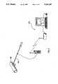
- FIG. 1is a schematic drawing of a data gathering apparatus in accordance with a preferred embodiment of the invention collecting data of an object
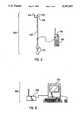
- FIG. 2is a schematic view illustrating the data gathering apparatus shown in FIG. 1;
- FIG. 3is a schematic view illustrating a model building apparatus in accordance with a preferred embodiment of the invention.
- FIG. 4is a schematic view illustrating the data gathering apparatus shown in FIG. 2 fitted with a wheel attachment for measurement of contoured surfaces in accordance with the invention
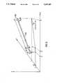
- FIG. 5is a schematic view illustrating the calculation of the position of the data gathering apparatus in accordance with the invention.
- FIG. 6is a schematic view illustrating a position and measurement system in conjunction with the data gathering apparatus shown in FIG. 2.
- FIG. 1A spatial measurement and recovery system in accordance with a preferred embodiment of the invention is shown in FIG. 1. Throughout the figures, like numerals are used to designate like elements.
- the data gathering apparatus 100gathers spatial/descriptive data of objects forming an environment for creating a "three-dimensional map" of the environment.
- a real time position determination systemis integrated into the data gathering apparatus 100, as will be explained in more detail below.
- the data gathering apparatusincludes one or more position sensors 110 (shown in FIG. 2).
- One preferred embodiment of the data gathering apparatus as shown in FIG. 2includes a rod 108 which is adapted to be hand held by an operator. It is contemplated that the rod may include flexible joints if the angular rotation of the joints is accounted for when determining position and orientation data.
- the operatorplaces the tip of the rod 108 on an object for which data is to be gathered.
- the touch sensor 112is triggered, which activates the computer/data storage device 120.
- the computer/data storage device 120is preferably connected to the rod via a communications link, such as via the cable shown in FIG. 2. Alternatively, the computer/data storage device 120 may be mounted on the rod itself.
- the computer/data storage device 120serves as an interface for the operator to enter data and to calibrate the positioning system and sensors. The operator may also communicate descriptive data (i.e., shape and operational characteristic data) and spatial data (i.e., position and orientation data) via a communications link, for example, by voice over a "walkie-talkie" system (not shown), to another operator who inputs the data into another apparatus for storage and/or data manipulation. It is contemplated that the computer/data storage device 120 may also have the capability to store spatial data and/or descriptive data of objects itself.
- the computer/data storage device 120selectively activates a shape sensor 114 and an operational sensor 118.
- the shape sensor 114can be of any suitable type which provides data which will distinguish the surface features of the object 300.
- the shape sensor 114may also be capable of providing data regarding interior features.
- a sonar devicemay be used as the shape sensor 114.
- Such a sonar devicecould include one or more directional audio transducers and receivers (not shown).
- Directional audio signalswould be aimed at different points on the object to determine the relative distance to the points. The distance to the points would give an indication of the shape of the object.
- a sounding device(not shown) in physical contact with the object 300 would transmit sound into the object and receive the resultant reflected sound. The sounding device may thus determine the thickness of materials composing the object at the point of contact. It is also envisioned that such a sounding device may be incorporated into the touch sensor 112.
- the data gathering apparatus 100may include an operational characteristic sensor 116.
- the operational characteristic sensor 116determines one or more operational characteristics of the object 300. Such operational characteristics may be used to distinguish an object from neighboring objects of similar shape. Operational characteristics which could be used as distinguishing traits may include, for example, temperature, material composition, electrical current and/or color or the like.
- a thermometeris used as operational characteristic sensor 116 to distinguish objects having unique operational temperatures or temperature ranges.
- a hardness testing devicecould be used as the operational characteristic sensor 116 to distinguish objects composed of outer materials having unique material hardness or material hardness ranges.
- a magnetic flux detectorcould be used as the operational characteristic sensor 116 to distinguish objects carrying different electrical currents.
- a cameramay be used as the operational characteristic sensor 116 to distinguish objects differing in color. It is to be understood that any desired operational characteristic and any corresponding operational characteristic sensor 116 may be used in connection with the system and method of the present invention.
- the data gathering apparatus 100may be fitted with various specialized attachments suitable for specialized data gathering.
- a wheel attachmentmay be used to enhance the gathering of data over contoured surfaces.
- two position sensors 110may be attached along the axis of the rod. Two position sensors used in this manner will provide the minimum information necessary to determine the position of the tip 130 of the data gathering apparatus 100.
- the position of the position sensors 110 along the rod 108are determined in reference to at least two fixed stations 500, as shown in FIG. 6.
- Each fixed stationpreferably produces a set or multiple sets of counter-rotating beams which rotate at a constant angular velocity.
- Such counter-rotating beamscan be produced using multiple rotating heads and strategically placed reflective surfaces, as shown in the Dornbusch et al. application referred to above.
- Each fixed station 500preferably includes a laser which produces at least one primary laser beam and at least one secondary beam which are counter-rotated about an axis.
- the primary laser beamhas a predetermined angle of divergence (i.e., spread) which is inclined at a predetermined angle from the rotational axis.
- the secondary beamhas the same divergence and may have the same inclination as the primary beam, but rotates in the opposite direction.
- a horizontal anglecan be determined from the time difference between the time of crossing of the primary and secondary beams. Once these horizontal angles are known for three fixed stations 500, the point of intersection of three planes, and thus the three-dimensional position of the position sensor 110 can be determined.
- the fixed stations 500each produce two primary laser beams and one or more secondary beams, only two fixed stations are required to determine the position of the position sensors 110 of the data gathering apparatus 100.
- the position of the tip of the rodcan be determined as follows:
- the orientation of an objectcan be determined if the position of three non-colinear points on the object are known.
- the location of a single pointis determined by the positioning system employed in the data gathering apparatus 100.
- the position of additional pointscan be generated through analysis of the shape data determined by the shape sensor 114.
- the accuracy of the determined orientationwill increase as the number of positions on the object from which the position data and shape data are taken increases.
- the model building apparatus 200stores the incoming spatial/descriptive data for the current object 300.
- the descriptive datais used to identify the object from a list of detailed descriptive data (e.g., actual design data) of previously recorded objects.
- This list of detailed descriptive datais preferably in the form of software object libraries contained within the model building apparatus 200.
- Small distancescan generally be accurately measured and precisely reproduced using commonly available instrumentation and tools, such as calipers, computer numerical controlled "CNC" machining equipment and the like.
- CNCcomputer numerical controlled
- the object libraries of the model building apparatus 200may contain the small dimensional information, such as the design shape data or production shape data, which is known to be accurate or which can be presumed to be accurate to the minimum accuracy required for the work at hand. In this way, the model building apparatus 200 can use the shape data provided by the data gathering apparatus to identify the data file in the object library which correspond to the object 300.
- the operator performing the data gatheringcan enter an identification code for the object into the computer/data storage device or directly into the model building apparatus 200.
- This codewould identify the appropriate descriptive data file without the need for analysis of the shape data of the object 300.
- the identification codecould be a manufacturer's part number, a design component number or any code which uniquely identified the object 300.
- the model building apparatus 200links the descriptive data to the position and orientation data generated by the data gathering apparatus 100.
- an operatorsystematically places the data gathering apparatus 100 on the objects composing the environment in the spatial/descriptive data is desired.
- the spatial/descriptive date for each objectis stored by the computer/data storage device 120.
- the spatial/descriptive datais directly transmitted to the model building apparatus 200.
- the model building apparatus 200records the spatial/descriptive data, matches the descriptive data to the reference data contained within the object libraries and places the CADD image of the object in the CADD model of the environment.
- the inventionis not limited to creating CADD models. It is also envisioned that the system and method of the invention can be used in navigational systems, for example, to allow robotic vehicles to navigate within their environments.
Landscapes
- Physics & Mathematics (AREA)
- Engineering & Computer Science (AREA)
- General Physics & Mathematics (AREA)
- Radar, Positioning & Navigation (AREA)
- Remote Sensing (AREA)
- Computer Networks & Wireless Communication (AREA)
- Electromagnetism (AREA)
- Length Measuring Devices With Unspecified Measuring Means (AREA)
- Steroid Compounds (AREA)
- Length Measuring Devices By Optical Means (AREA)
Abstract
Description
X=L/D(X.sub.2 -X.sub.1)+X.sub.2
Y=L/D(Y.sub.2 -Y.sub.1)+Y.sub.1
Z=L/D(Z.sub.2 -Z.sub.1)+Z.sub.1
Claims (13)
Priority Applications (9)
| Application Number | Priority Date | Filing Date | Title |
|---|---|---|---|
| US07/714,891US5247487A (en) | 1991-06-17 | 1991-06-17 | Spatial measurement recovery system |
| AT92914081TATE208903T1 (en) | 1991-06-17 | 1992-06-17 | SYSTEM FOR TAKING SPATIAL MEASUREMENTS |
| JP50110593AJP3252965B2 (en) | 1991-06-17 | 1992-06-17 | Spatial measurement restoration system |
| PCT/US1992/005132WO1992022832A1 (en) | 1991-06-17 | 1992-06-17 | Spatial measurement recovery system |
| DE69232203TDE69232203T2 (en) | 1991-06-17 | 1992-06-17 | SYSTEM FOR TAKING SPATIAL MEASUREMENTS |
| CA002111117ACA2111117C (en) | 1991-06-17 | 1992-06-17 | Spatial measurement recovery system |
| EP92914081AEP0592515B1 (en) | 1991-06-17 | 1992-06-17 | Spatial measurement recovery system |
| US08/123,891US5461473A (en) | 1990-12-31 | 1993-09-20 | Transmitter and receiver units for spatial position measurement system |
| US08/539,379US5579102A (en) | 1991-06-17 | 1995-10-05 | Transmitter and receiver units for spatial position measurement system |
Applications Claiming Priority (1)
| Application Number | Priority Date | Filing Date | Title |
|---|---|---|---|
| US07/714,891US5247487A (en) | 1991-06-17 | 1991-06-17 | Spatial measurement recovery system |
Related Child Applications (2)
| Application Number | Title | Priority Date | Filing Date |
|---|---|---|---|
| US08/123,891Continuation-In-PartUS5461473A (en) | 1990-12-31 | 1993-09-20 | Transmitter and receiver units for spatial position measurement system |
| US12389195AContinuation-In-Part | 1991-06-17 | 1995-10-05 |
Publications (1)
| Publication Number | Publication Date |
|---|---|
| US5247487Atrue US5247487A (en) | 1993-09-21 |
Family
ID=24871875
Family Applications (1)
| Application Number | Title | Priority Date | Filing Date |
|---|---|---|---|
| US07/714,891Expired - LifetimeUS5247487A (en) | 1990-12-31 | 1991-06-17 | Spatial measurement recovery system |
Country Status (7)
| Country | Link |
|---|---|
| US (1) | US5247487A (en) |
| EP (1) | EP0592515B1 (en) |
| JP (1) | JP3252965B2 (en) |
| AT (1) | ATE208903T1 (en) |
| CA (1) | CA2111117C (en) |
| DE (1) | DE69232203T2 (en) |
| WO (1) | WO1992022832A1 (en) |
Cited By (28)
| Publication number | Priority date | Publication date | Assignee | Title |
|---|---|---|---|---|
| US5579102A (en)* | 1991-06-17 | 1996-11-26 | Spatial Positioning Systems, Inc. | Transmitter and receiver units for spatial position measurement system |
| US5675514A (en)* | 1996-04-10 | 1997-10-07 | Lefebvre; Guy | Telemetric spacial data recorder |
| US5729475A (en)* | 1995-12-27 | 1998-03-17 | Romanik, Jr.; Carl J. | Optical system for accurate monitoring of the position and orientation of an object |
| US5956661A (en)* | 1996-10-23 | 1999-09-21 | Lasercad Inc. | Telemetric spacial data recorder |
| US6108271A (en)* | 1998-12-10 | 2000-08-22 | Erskine College | Remote control device for controlling electronic devices |
| WO2000057132A1 (en)* | 1999-03-22 | 2000-09-28 | Arc Second, Inc. | Method for creating a user-selectable coordinate frame |
| WO2000057133A1 (en)* | 1999-03-22 | 2000-09-28 | Arc Second, Inc. | Calibration of optical transmitter for position measurement systems |
| WO2000057131A1 (en)* | 1999-03-22 | 2000-09-28 | Arc Second, Inc. | Method for establishing a coordinate system |
| FR2803031A1 (en)* | 1999-12-24 | 2001-06-29 | Bosch Gmbh Robert | CALIBRATION METHOD OF A SENSOR SYSTEM |
| WO2001061278A1 (en)* | 2000-02-18 | 2001-08-23 | Scertab - Societe Civile D'etudes Et De Recherche En Telemetrie Appliquee Au Batiment | Telemetric equipment for two-dimensional or three-dimensional cartography of a volume |
| WO2001065207A3 (en)* | 2000-02-28 | 2002-04-18 | Arc Second Inc | Apparatus and method for determining position |
| US6452668B1 (en) | 1998-10-13 | 2002-09-17 | Arc Second, Inc. | Rotating head optical transmitter for position measurement system |
| US6519029B1 (en) | 1999-03-22 | 2003-02-11 | Arc Second, Inc. | Low cost transmitter with calibration means for use in position measurement systems |
| US6545751B2 (en)* | 2000-02-28 | 2003-04-08 | Arc Second, Inc. | Low cost 2D position measurement system and method |
| US20030174305A1 (en)* | 2000-08-01 | 2003-09-18 | Michael Kasper | Measuring device and measuring method for determining distance and/or position |
| US6630993B1 (en) | 1999-03-22 | 2003-10-07 | Arc Second Inc. | Method and optical receiver with easy setup means for use in position measurement systems |
| US6643004B2 (en)* | 2000-03-10 | 2003-11-04 | Trimble Navigation Limited | Versatile transmitter and receiver for position measurement |
| US6662103B1 (en) | 1999-03-22 | 2003-12-09 | Arc Second Inc. | Method and system for creating a user-selectable arbitrary coordinate frame |
| US20080015811A1 (en)* | 2006-07-12 | 2008-01-17 | Apache Technologies, Inc. | Handheld laser light detector with height correction, using a GPS receiver to provide two-dimensional position data |
| US20080079955A1 (en)* | 2006-10-03 | 2008-04-03 | Storm Thomas W | Apparatus and method fro measuring volumes |
| EP1936399A3 (en)* | 2006-12-20 | 2008-09-10 | CSL Surveys (Stevenage) limited | Profiling device |
| US20090046269A1 (en)* | 2004-11-03 | 2009-02-19 | Mirko Essling | Light beam receiver |
| EP2067004A4 (en)* | 2006-09-26 | 2011-01-19 | Samsung Heavy Ind | Three-dimensional measurement system and rescaling method using indoor gps |
| US8711335B2 (en) | 2011-06-28 | 2014-04-29 | Nikon Corporation | Stroboscopic light source for a transmitter of a large scale metrology system |
| EP3367118A2 (en) | 2016-07-13 | 2018-08-29 | Alexei Vyssotski | Ultrasonic and optical tracking method for small animal research |
| US10286308B2 (en) | 2014-11-10 | 2019-05-14 | Valve Corporation | Controller visualization in virtual and augmented reality environments |
| CN110515057A (en)* | 2019-04-10 | 2019-11-29 | 青岛镭测创芯科技有限公司 | A multi-directional optical collimation transceiver device integrating transceiver |
| US20200285639A1 (en)* | 2019-03-05 | 2020-09-10 | At&T Intellectual Property I, L.P. | Apparatus and method to isolate vectors in an arbitrarily large n-space |
Families Citing this family (1)
| Publication number | Priority date | Publication date | Assignee | Title |
|---|---|---|---|---|
| US5771978A (en)* | 1996-06-05 | 1998-06-30 | Kabushiki Kaisha Topcon | Grading implement elevation controller with tracking station and reference laser beam |
Citations (2)
| Publication number | Priority date | Publication date | Assignee | Title |
|---|---|---|---|---|
| US5031154A (en)* | 1989-09-04 | 1991-07-09 | Ricoh Company, Ltd. | Three-dimensional object imaging method and system |
| US5121333A (en)* | 1989-06-09 | 1992-06-09 | Regents Of The University Of Minnesota | Method and apparatus for manipulating computer-based representations of objects of complex and unique geometry |
Family Cites Families (2)
| Publication number | Priority date | Publication date | Assignee | Title |
|---|---|---|---|---|
| GB2152320A (en)* | 1983-12-07 | 1985-07-31 | Robert James Siddall | Position location system |
| DE3717708A1 (en)* | 1987-05-23 | 1988-12-08 | Prakla Seismos Ag | METHOD FOR DETERMINING THE LOCATION OF CABLE SECTIONS TOWED BEHIND A SHIP |
- 1991
- 1991-06-17USUS07/714,891patent/US5247487A/ennot_activeExpired - Lifetime
- 1992
- 1992-06-17ATAT92914081Tpatent/ATE208903T1/ennot_activeIP Right Cessation
- 1992-06-17DEDE69232203Tpatent/DE69232203T2/ennot_activeExpired - Fee Related
- 1992-06-17JPJP50110593Apatent/JP3252965B2/ennot_activeExpired - Lifetime
- 1992-06-17EPEP92914081Apatent/EP0592515B1/ennot_activeExpired - Lifetime
- 1992-06-17CACA002111117Apatent/CA2111117C/ennot_activeExpired - Fee Related
- 1992-06-17WOPCT/US1992/005132patent/WO1992022832A1/enactiveIP Right Grant
Patent Citations (2)
| Publication number | Priority date | Publication date | Assignee | Title |
|---|---|---|---|---|
| US5121333A (en)* | 1989-06-09 | 1992-06-09 | Regents Of The University Of Minnesota | Method and apparatus for manipulating computer-based representations of objects of complex and unique geometry |
| US5031154A (en)* | 1989-09-04 | 1991-07-09 | Ricoh Company, Ltd. | Three-dimensional object imaging method and system |
Cited By (46)
| Publication number | Priority date | Publication date | Assignee | Title |
|---|---|---|---|---|
| US5579102A (en)* | 1991-06-17 | 1996-11-26 | Spatial Positioning Systems, Inc. | Transmitter and receiver units for spatial position measurement system |
| US5729475A (en)* | 1995-12-27 | 1998-03-17 | Romanik, Jr.; Carl J. | Optical system for accurate monitoring of the position and orientation of an object |
| US5884239A (en)* | 1995-12-27 | 1999-03-16 | Romanik, Jr.; Carl J. | Optical system for accurate monitoring of the position and orientation of an object |
| US5675514A (en)* | 1996-04-10 | 1997-10-07 | Lefebvre; Guy | Telemetric spacial data recorder |
| US5956661A (en)* | 1996-10-23 | 1999-09-21 | Lasercad Inc. | Telemetric spacial data recorder |
| US6621565B2 (en)* | 1998-10-13 | 2003-09-16 | Arc Second Inc. | Rotating head optical transmitter for position measurement system |
| US6452668B1 (en) | 1998-10-13 | 2002-09-17 | Arc Second, Inc. | Rotating head optical transmitter for position measurement system |
| US6108271A (en)* | 1998-12-10 | 2000-08-22 | Erskine College | Remote control device for controlling electronic devices |
| WO2000057131A1 (en)* | 1999-03-22 | 2000-09-28 | Arc Second, Inc. | Method for establishing a coordinate system |
| WO2000057133A1 (en)* | 1999-03-22 | 2000-09-28 | Arc Second, Inc. | Calibration of optical transmitter for position measurement systems |
| US6662103B1 (en) | 1999-03-22 | 2003-12-09 | Arc Second Inc. | Method and system for creating a user-selectable arbitrary coordinate frame |
| US6630993B1 (en) | 1999-03-22 | 2003-10-07 | Arc Second Inc. | Method and optical receiver with easy setup means for use in position measurement systems |
| WO2000057132A1 (en)* | 1999-03-22 | 2000-09-28 | Arc Second, Inc. | Method for creating a user-selectable coordinate frame |
| US6519029B1 (en) | 1999-03-22 | 2003-02-11 | Arc Second, Inc. | Low cost transmitter with calibration means for use in position measurement systems |
| US6618133B2 (en)* | 1999-03-22 | 2003-09-09 | Arc Second, Inc. | Low cost transmitter with calibration means for use in position measurement systems |
| FR2803031A1 (en)* | 1999-12-24 | 2001-06-29 | Bosch Gmbh Robert | CALIBRATION METHOD OF A SENSOR SYSTEM |
| US6778928B2 (en)* | 1999-12-24 | 2004-08-17 | Robert Bosch Gmbh | Method of calibrating a sensor system |
| WO2001061278A1 (en)* | 2000-02-18 | 2001-08-23 | Scertab - Societe Civile D'etudes Et De Recherche En Telemetrie Appliquee Au Batiment | Telemetric equipment for two-dimensional or three-dimensional cartography of a volume |
| US6683694B2 (en) | 2000-02-18 | 2004-01-27 | Scertab - Societe Civile D'etudes Et De Recherche En Telemetrie Appliquee Au Batiment | Telemetry equipment for the two-dimensional or three-dimensional mapping of a volume |
| FR2805350A1 (en)* | 2000-02-18 | 2001-08-24 | Scertab Soc Civ Ile D Etudes E | TELEMETRY EQUIPMENT FOR BI- OR THREE-DIMENSIONAL MAPPING OF A VOLUME |
| US6545751B2 (en)* | 2000-02-28 | 2003-04-08 | Arc Second, Inc. | Low cost 2D position measurement system and method |
| WO2001065207A3 (en)* | 2000-02-28 | 2002-04-18 | Arc Second Inc | Apparatus and method for determining position |
| US20040008338A1 (en)* | 2000-03-10 | 2004-01-15 | Detweiler Philip L. | Versatile transmitter and receiver for position measurement |
| US6643004B2 (en)* | 2000-03-10 | 2003-11-04 | Trimble Navigation Limited | Versatile transmitter and receiver for position measurement |
| US6870608B2 (en) | 2000-03-10 | 2005-03-22 | Trimble Navigation Limited | Versatile transmitter and receiver for position measurement |
| US20050122507A1 (en)* | 2000-03-10 | 2005-06-09 | Detweiler Philip L. | Versatile transmitter and receiver for position measurement |
| US7064819B2 (en) | 2000-03-10 | 2006-06-20 | Trimble Navigation Limited | Versatile transmitter and receiver for position measurement |
| US20030174305A1 (en)* | 2000-08-01 | 2003-09-18 | Michael Kasper | Measuring device and measuring method for determining distance and/or position |
| US7110092B2 (en) | 2000-08-01 | 2006-09-19 | Michael Kasper | Measuring device and measuring method for determining distance and/or position |
| US20070024845A1 (en)* | 2000-08-01 | 2007-02-01 | Androtec Gmbh | Measuring device and measuring method for determining distance and/or position |
| US7394527B2 (en) | 2000-08-01 | 2008-07-01 | Androtec Gmbh | Measuring device and measuring method for determining distance and/or position |
| US7724352B2 (en) | 2004-11-03 | 2010-05-25 | Androtec Gmbh | Light beam receiver |
| US20090046269A1 (en)* | 2004-11-03 | 2009-02-19 | Mirko Essling | Light beam receiver |
| US7409312B2 (en) | 2006-07-12 | 2008-08-05 | Apache Technologies, Inc. | Handheld laser light detector with height correction, using a GPS receiver to provide two-dimensional position data |
| US20080015811A1 (en)* | 2006-07-12 | 2008-01-17 | Apache Technologies, Inc. | Handheld laser light detector with height correction, using a GPS receiver to provide two-dimensional position data |
| EP2067004A4 (en)* | 2006-09-26 | 2011-01-19 | Samsung Heavy Ind | Three-dimensional measurement system and rescaling method using indoor gps |
| US20080079955A1 (en)* | 2006-10-03 | 2008-04-03 | Storm Thomas W | Apparatus and method fro measuring volumes |
| US7576871B2 (en)* | 2006-10-03 | 2009-08-18 | Storm Thomas W | Apparatus and method for measuring volumes |
| EP1936399A3 (en)* | 2006-12-20 | 2008-09-10 | CSL Surveys (Stevenage) limited | Profiling device |
| US8711335B2 (en) | 2011-06-28 | 2014-04-29 | Nikon Corporation | Stroboscopic light source for a transmitter of a large scale metrology system |
| US10286308B2 (en) | 2014-11-10 | 2019-05-14 | Valve Corporation | Controller visualization in virtual and augmented reality environments |
| US11045725B1 (en) | 2014-11-10 | 2021-06-29 | Valve Corporation | Controller visualization in virtual and augmented reality environments |
| EP3367118A2 (en) | 2016-07-13 | 2018-08-29 | Alexei Vyssotski | Ultrasonic and optical tracking method for small animal research |
| US11134864B2 (en) | 2016-07-13 | 2021-10-05 | Alexei L. Vyssotski | Tracking method and system for small animal research |
| US20200285639A1 (en)* | 2019-03-05 | 2020-09-10 | At&T Intellectual Property I, L.P. | Apparatus and method to isolate vectors in an arbitrarily large n-space |
| CN110515057A (en)* | 2019-04-10 | 2019-11-29 | 青岛镭测创芯科技有限公司 | A multi-directional optical collimation transceiver device integrating transceiver |
Also Published As
| Publication number | Publication date |
|---|---|
| JP3252965B2 (en) | 2002-02-04 |
| WO1992022832A1 (en) | 1992-12-23 |
| EP0592515A1 (en) | 1994-04-20 |
| JPH09506164A (en) | 1997-06-17 |
| CA2111117C (en) | 1998-01-20 |
| EP0592515B1 (en) | 2001-11-14 |
| CA2111117A1 (en) | 1992-12-23 |
| DE69232203D1 (en) | 2001-12-20 |
| EP0592515A4 (en) | 1995-05-17 |
| ATE208903T1 (en) | 2001-11-15 |
| DE69232203T2 (en) | 2002-08-14 |
Similar Documents
| Publication | Publication Date | Title |
|---|---|---|
| US5247487A (en) | Spatial measurement recovery system | |
| US6662103B1 (en) | Method and system for creating a user-selectable arbitrary coordinate frame | |
| EP1893942B1 (en) | Apparatus and method for relocating an articulating-arm coordinate measuring machine | |
| EP1775077B1 (en) | Parallel kinematic machine, calibration method of parallel kinematic machine, and calibration program product | |
| EP2350562B1 (en) | Positioning interface for spatial query | |
| US6941192B2 (en) | Robot machining tool position and orientation calibration | |
| EP2972084B1 (en) | System and method for positioning a tool in a work space | |
| JPH09295043A (en) | Method for manufacturing a bent tube | |
| US20070242280A1 (en) | Digitizer adapter | |
| US6683694B2 (en) | Telemetry equipment for the two-dimensional or three-dimensional mapping of a volume | |
| WO2001077613A1 (en) | Measurement system and method | |
| JP2003526774A (en) | How to set the coordinate system | |
| CN102203768A (en) | System and method for electronic inspection and record creation of assembly, repair and maintenance operations | |
| JP2007506076A5 (en) | ||
| EP3693697B1 (en) | Method for calibrating a 3d measurement arrangement and 3d measurement arrangement | |
| JPH06265307A (en) | Method and apparatus for decision of position of reverse reflecting element | |
| White et al. | A mobile climbing robot for high precision manufacture and inspection of aerostructures | |
| WO2018097784A1 (en) | Measurement system and method of an industrial robot | |
| JP2009503711A (en) | Method and system for determining the relative position of a first object with respect to a second object, a corresponding computer program and a corresponding computer-readable recording medium | |
| WO1993008449A1 (en) | Measuring the accuracy of multi-axis machines | |
| Maisano et al. | Dimensional measurements in the shipbuilding industry: on-site comparison of a state-of-the-art laser tracker, total station and laser scanner | |
| Mason | Heuristic reasoning strategy for automated sensor placement | |
| CN114562994A (en) | Localization method of mobile robot in dynamic environment | |
| Artkin | CMM machines and industrial applications | |
| US20050046871A1 (en) | Apparatus for and method of measurements of components |
Legal Events
| Date | Code | Title | Description |
|---|---|---|---|
| AS | Assignment | Owner name:SPATIAL POSITIONING SYSTEMS, INC., A CORPORATION O Free format text:ASSIGNMENT OF ASSIGNORS INTEREST.;ASSIGNORS:BELIVEAU, YVAN J.;LUNDBERG, ERIC J.;DORNBUSCH, ANDREW;AND OTHERS;REEL/FRAME:005808/0893 Effective date:19910808 | |
| STCF | Information on status: patent grant | Free format text:PATENTED CASE | |
| REMI | Maintenance fee reminder mailed | ||
| FPAY | Fee payment | Year of fee payment:4 | |
| SULP | Surcharge for late payment | ||
| AS | Assignment | Owner name:ARC SECOND, INC., VIRGINIA Free format text:CHANGE OF NAME;ASSIGNOR:SPATIAL POSITIONING SYSTEMS, INC.;REEL/FRAME:009547/0941 Effective date:19980309 | |
| AS | Assignment | Owner name:PNC BANK, NATIONAL ASSOCIATION, PENNSYLVANIA Free format text:SECURITY AGREEMENT;ASSIGNOR:ARC SECOND, INC.;REEL/FRAME:010371/0167 Effective date:19991001 | |
| AS | Assignment | Owner name:IMPERIAL BANK, CALIFORNIA Free format text:SECURITY INTEREST;ASSIGNOR:ARC SECOND, INC.;REEL/FRAME:011190/0537 Effective date:20000615 | |
| FEPP | Fee payment procedure | Free format text:PAT HLDR NO LONGER CLAIMS SMALL ENT STAT AS INDIV INVENTOR (ORIGINAL EVENT CODE: LSM1); ENTITY STATUS OF PATENT OWNER: LARGE ENTITY | |
| FPAY | Fee payment | Year of fee payment:8 | |
| AS | Assignment | Owner name:ARC SECOND, INC., VIRGINIA Free format text:RELEASE OF SECURITY INTEREST;ASSIGNOR:IMPERIAL BANK;REEL/FRAME:012014/0852 Effective date:20010712 | |
| AS | Assignment | Owner name:SOFINOV, SOCIETE FINANCIERE D'INNOVATION INC., CAN Free format text:SECURITY INTEREST;ASSIGNOR:ARC SECOND, INC.;REEL/FRAME:012166/0072 Effective date:20010709 | |
| REMI | Maintenance fee reminder mailed | ||
| FPAY | Fee payment | Year of fee payment:12 | |
| SULP | Surcharge for late payment | Year of fee payment:11 | |
| AS | Assignment | Owner name:NIKON METROLOGY, INC., MICHIGAN Free format text:ASSIGNMENT OF ASSIGNORS INTEREST;ASSIGNOR:ARC3 HOLDINGS, LLC;REEL/FRAME:025513/0810 Effective date:20101007 Owner name:NIKON METROLOGY, NV, BELGIUM Free format text:ASSIGNMENT OF ASSIGNORS INTEREST;ASSIGNOR:NIKON METROLOGY, INC.;REEL/FRAME:025513/0857 Effective date:20101030 |