US5247174A - Laser scanning apparatus having a scanning beam and a reference beam - Google Patents
Laser scanning apparatus having a scanning beam and a reference beamDownload PDFInfo
- Publication number
- US5247174A US5247174AUS07/691,228US69122891AUS5247174AUS 5247174 AUS5247174 AUS 5247174AUS 69122891 AUS69122891 AUS 69122891AUS 5247174 AUS5247174 AUS 5247174A
- Authority
- US
- United States
- Prior art keywords
- scanning apparatus
- scanning
- laser
- laser scanning
- fiber optic
- Prior art date
- Legal status (The legal status is an assumption and is not a legal conclusion. Google has not performed a legal analysis and makes no representation as to the accuracy of the status listed.)
- Expired - Fee Related
Links
Images


Classifications
- H—ELECTRICITY
- H04—ELECTRIC COMMUNICATION TECHNIQUE
- H04N—PICTORIAL COMMUNICATION, e.g. TELEVISION
- H04N1/00—Scanning, transmission or reproduction of documents or the like, e.g. facsimile transmission; Details thereof
- H04N1/04—Scanning arrangements, i.e. arrangements for the displacement of active reading or reproducing elements relative to the original or reproducing medium, or vice versa
- H04N1/047—Detection, control or error compensation of scanning velocity or position
- G—PHYSICS
- G02—OPTICS
- G02B—OPTICAL ELEMENTS, SYSTEMS OR APPARATUS
- G02B26/00—Optical devices or arrangements for the control of light using movable or deformable optical elements
- G02B26/08—Optical devices or arrangements for the control of light using movable or deformable optical elements for controlling the direction of light
- G02B26/10—Scanning systems
- G02B26/103—Scanning systems having movable or deformable optical fibres, light guides or waveguides as scanning elements
- G—PHYSICS
- G02—OPTICS
- G02B—OPTICAL ELEMENTS, SYSTEMS OR APPARATUS
- G02B26/00—Optical devices or arrangements for the control of light using movable or deformable optical elements
- G02B26/08—Optical devices or arrangements for the control of light using movable or deformable optical elements for controlling the direction of light
- G02B26/10—Scanning systems
- G02B26/12—Scanning systems using multifaceted mirrors
- G02B26/123—Multibeam scanners, e.g. using multiple light sources or beam splitters
- H—ELECTRICITY
- H04—ELECTRIC COMMUNICATION TECHNIQUE
- H04N—PICTORIAL COMMUNICATION, e.g. TELEVISION
- H04N1/00—Scanning, transmission or reproduction of documents or the like, e.g. facsimile transmission; Details thereof
- H04N1/04—Scanning arrangements, i.e. arrangements for the displacement of active reading or reproducing elements relative to the original or reproducing medium, or vice versa
- H04N1/10—Scanning arrangements, i.e. arrangements for the displacement of active reading or reproducing elements relative to the original or reproducing medium, or vice versa using flat picture-bearing surfaces
- H04N1/1008—Scanning arrangements, i.e. arrangements for the displacement of active reading or reproducing elements relative to the original or reproducing medium, or vice versa using flat picture-bearing surfaces with sub-scanning by translatory movement of the picture-bearing surface
- H—ELECTRICITY
- H04—ELECTRIC COMMUNICATION TECHNIQUE
- H04N—PICTORIAL COMMUNICATION, e.g. TELEVISION
- H04N1/00—Scanning, transmission or reproduction of documents or the like, e.g. facsimile transmission; Details thereof
- H04N1/04—Scanning arrangements, i.e. arrangements for the displacement of active reading or reproducing elements relative to the original or reproducing medium, or vice versa
- H04N1/10—Scanning arrangements, i.e. arrangements for the displacement of active reading or reproducing elements relative to the original or reproducing medium, or vice versa using flat picture-bearing surfaces
- H04N1/1013—Scanning arrangements, i.e. arrangements for the displacement of active reading or reproducing elements relative to the original or reproducing medium, or vice versa using flat picture-bearing surfaces with sub-scanning by translatory movement of at least a part of the main-scanning components
- H—ELECTRICITY
- H04—ELECTRIC COMMUNICATION TECHNIQUE
- H04N—PICTORIAL COMMUNICATION, e.g. TELEVISION
- H04N1/00—Scanning, transmission or reproduction of documents or the like, e.g. facsimile transmission; Details thereof
- H04N1/04—Scanning arrangements, i.e. arrangements for the displacement of active reading or reproducing elements relative to the original or reproducing medium, or vice versa
- H04N1/113—Scanning arrangements, i.e. arrangements for the displacement of active reading or reproducing elements relative to the original or reproducing medium, or vice versa using oscillating or rotating mirrors
- H04N1/1135—Scanning arrangements, i.e. arrangements for the displacement of active reading or reproducing elements relative to the original or reproducing medium, or vice versa using oscillating or rotating mirrors for the main-scan only
- H—ELECTRICITY
- H04—ELECTRIC COMMUNICATION TECHNIQUE
- H04N—PICTORIAL COMMUNICATION, e.g. TELEVISION
- H04N2201/00—Indexing scheme relating to scanning, transmission or reproduction of documents or the like, and to details thereof
- H04N2201/024—Indexing scheme relating to scanning, transmission or reproduction of documents or the like, and to details thereof deleted
- H04N2201/02406—Arrangements for positioning elements within a head
- H04N2201/02439—Positioning method
- H04N2201/02441—Positioning method using screws
- H—ELECTRICITY
- H04—ELECTRIC COMMUNICATION TECHNIQUE
- H04N—PICTORIAL COMMUNICATION, e.g. TELEVISION
- H04N2201/00—Indexing scheme relating to scanning, transmission or reproduction of documents or the like, and to details thereof
- H04N2201/024—Indexing scheme relating to scanning, transmission or reproduction of documents or the like, and to details thereof deleted
- H04N2201/02406—Arrangements for positioning elements within a head
- H04N2201/02439—Positioning method
- H04N2201/02443—Positioning method using adhesive
- H—ELECTRICITY
- H04—ELECTRIC COMMUNICATION TECHNIQUE
- H04N—PICTORIAL COMMUNICATION, e.g. TELEVISION
- H04N2201/00—Indexing scheme relating to scanning, transmission or reproduction of documents or the like, and to details thereof
- H04N2201/04—Scanning arrangements
- H04N2201/047—Detection, control or error compensation of scanning velocity or position
- H04N2201/04701—Detection of scanning velocity or position
- H04N2201/0471—Detection of scanning velocity or position using dedicated detectors
- H04N2201/04712—Detection of scanning velocity or position using dedicated detectors using unbroken arrays of detectors, i.e. detectors mounted on the same substrate
- H—ELECTRICITY
- H04—ELECTRIC COMMUNICATION TECHNIQUE
- H04N—PICTORIAL COMMUNICATION, e.g. TELEVISION
- H04N2201/00—Indexing scheme relating to scanning, transmission or reproduction of documents or the like, and to details thereof
- H04N2201/04—Scanning arrangements
- H04N2201/047—Detection, control or error compensation of scanning velocity or position
- H04N2201/04701—Detection of scanning velocity or position
- H04N2201/04729—Detection of scanning velocity or position in the main-scan direction
- H—ELECTRICITY
- H04—ELECTRIC COMMUNICATION TECHNIQUE
- H04N—PICTORIAL COMMUNICATION, e.g. TELEVISION
- H04N2201/00—Indexing scheme relating to scanning, transmission or reproduction of documents or the like, and to details thereof
- H04N2201/04—Scanning arrangements
- H04N2201/047—Detection, control or error compensation of scanning velocity or position
- H04N2201/04701—Detection of scanning velocity or position
- H04N2201/04731—Detection of scanning velocity or position in the sub-scan direction
- H—ELECTRICITY
- H04—ELECTRIC COMMUNICATION TECHNIQUE
- H04N—PICTORIAL COMMUNICATION, e.g. TELEVISION
- H04N2201/00—Indexing scheme relating to scanning, transmission or reproduction of documents or the like, and to details thereof
- H04N2201/04—Scanning arrangements
- H04N2201/047—Detection, control or error compensation of scanning velocity or position
- H04N2201/04701—Detection of scanning velocity or position
- H04N2201/04734—Detecting at frequent intervals, e.g. once per line for sub-scan control
- H—ELECTRICITY
- H04—ELECTRIC COMMUNICATION TECHNIQUE
- H04N—PICTORIAL COMMUNICATION, e.g. TELEVISION
- H04N2201/00—Indexing scheme relating to scanning, transmission or reproduction of documents or the like, and to details thereof
- H04N2201/04—Scanning arrangements
- H04N2201/047—Detection, control or error compensation of scanning velocity or position
- H04N2201/04701—Detection of scanning velocity or position
- H04N2201/04744—Detection of scanning velocity or position by detecting the scanned beam or a reference beam
- H—ELECTRICITY
- H04—ELECTRIC COMMUNICATION TECHNIQUE
- H04N—PICTORIAL COMMUNICATION, e.g. TELEVISION
- H04N2201/00—Indexing scheme relating to scanning, transmission or reproduction of documents or the like, and to details thereof
- H04N2201/04—Scanning arrangements
- H04N2201/047—Detection, control or error compensation of scanning velocity or position
- H04N2201/04753—Control or error compensation of scanning position or velocity
- H04N2201/04758—Control or error compensation of scanning position or velocity by controlling the position of the scanned image area
- H04N2201/0476—Control or error compensation of scanning position or velocity by controlling the position of the scanned image area using an optical, electro-optical or acousto-optical element
- H04N2201/04765—Control or error compensation of scanning position or velocity by controlling the position of the scanned image area using an optical, electro-optical or acousto-optical element using a solid-state deflector, e.g. an acousto-optic deflector
- H—ELECTRICITY
- H04—ELECTRIC COMMUNICATION TECHNIQUE
- H04N—PICTORIAL COMMUNICATION, e.g. TELEVISION
- H04N2201/00—Indexing scheme relating to scanning, transmission or reproduction of documents or the like, and to details thereof
- H04N2201/04—Scanning arrangements
- H04N2201/047—Detection, control or error compensation of scanning velocity or position
- H04N2201/04753—Control or error compensation of scanning position or velocity
- H04N2201/04758—Control or error compensation of scanning position or velocity by controlling the position of the scanned image area
- H04N2201/04767—Control or error compensation of scanning position or velocity by controlling the position of the scanned image area by controlling the timing of the signals, e.g. by controlling the frequency o phase of the pixel clock
- H04N2201/04768—Controlling the frequency of the signals
- H04N2201/04772—Controlling the frequency of the signals using a phase-locked loop
- H—ELECTRICITY
- H04—ELECTRIC COMMUNICATION TECHNIQUE
- H04N—PICTORIAL COMMUNICATION, e.g. TELEVISION
- H04N2201/00—Indexing scheme relating to scanning, transmission or reproduction of documents or the like, and to details thereof
- H04N2201/04—Scanning arrangements
- H04N2201/047—Detection, control or error compensation of scanning velocity or position
- H04N2201/04753—Control or error compensation of scanning position or velocity
- H04N2201/04789—Control or error compensation of scanning position or velocity in the main-scan direction
- H—ELECTRICITY
- H04—ELECTRIC COMMUNICATION TECHNIQUE
- H04N—PICTORIAL COMMUNICATION, e.g. TELEVISION
- H04N2201/00—Indexing scheme relating to scanning, transmission or reproduction of documents or the like, and to details thereof
- H04N2201/04—Scanning arrangements
- H04N2201/047—Detection, control or error compensation of scanning velocity or position
- H04N2201/04753—Control or error compensation of scanning position or velocity
- H04N2201/04791—Control or error compensation of scanning position or velocity in the sub-scan direction
- H—ELECTRICITY
- H04—ELECTRIC COMMUNICATION TECHNIQUE
- H04N—PICTORIAL COMMUNICATION, e.g. TELEVISION
- H04N2201/00—Indexing scheme relating to scanning, transmission or reproduction of documents or the like, and to details thereof
- H04N2201/04—Scanning arrangements
- H04N2201/047—Detection, control or error compensation of scanning velocity or position
- H04N2201/04753—Control or error compensation of scanning position or velocity
- H04N2201/04794—Varying the control or compensation during the scan, e.g. using continuous feedback or from line to line
- H04N2201/04796—Varying the sub-scan control during the main-scan, e.g. for correcting skew, tilt or bow of a scanning beam
- H—ELECTRICITY
- H04—ELECTRIC COMMUNICATION TECHNIQUE
- H04N—PICTORIAL COMMUNICATION, e.g. TELEVISION
- H04N2201/00—Indexing scheme relating to scanning, transmission or reproduction of documents or the like, and to details thereof
- H04N2201/04—Scanning arrangements
- H04N2201/047—Detection, control or error compensation of scanning velocity or position
- H04N2201/04753—Control or error compensation of scanning position or velocity
- H04N2201/04794—Varying the control or compensation during the scan, e.g. using continuous feedback or from line to line
- H04N2201/04798—Varying the main-scan control during the main-scan, e.g. facet tracking
Definitions
- the present inventionrelates to laser beam scanning apparatus generally, and to laser beam scanning apparatus utilizing fiber optics in particular.
- scanningis taken to indicate both the read-in of data from an image to be scanned and the write-out of data to produce an image.
- Various laser scanning devicesare known in the art. They typically comprise a laser source and optical elements for bringing the laser light produced by the laser source to a scanning medium.
- U.S. Pat. No. 4,746,180 to Deisler et. al.describes a laser scanning device composed of at least one multi-mode fiber optical light lightguide and one guide element for the fiber optical lightguide.
- multi-mode fiber optical lightguideswill produce inhomogeneous light distributions on an exit face in the face of a change of curvature, typically due to motion of one portion of the lightguide.
- the device of U.S. Pat. No. 4,746,180utilizes a rigid guide element to ensure that the curvature of the multi-mode fiber optical lightguide is maintained during movement of the exit face of the lightguide. It is a further purpose of the present invention to utilize fiber optical lightguides which can move freely while maintaining a constant light distribution at their exit faces.
- the present inventionseeks to provide laser beam scanning apparatus utilizing single-mode fiber optics.
- laser scanning apparatuscomprising stationary optical laser source apparatus for producing a scanning beam and a reference beam, beam delivery apparatus for delivering the scanning beam onto a surface to be scanned, beam position detector apparatus for measuring the position of the scanning beam by sensing the position of the reference beam and fiber optic apparatus for delivering the scanning beam and the reference beam from the optical laser source apparatus to the beam delivery apparatus.
- the fiber optic apparatuscomprises at least one single-mode fiber optic lightguide.
- the laser scanning apparatusalso comprises actuator apparatus attached to exit ends of the fiber optic apparatus and closed loop control apparatus for controlling the actuator apparatus in response to measurements produced by the beam detector apparatus.
- the actuator apparatusis a piezoelectric actuator.
- the beam delivery apparatusincludes motor apparatus for translation thereof.
- the closed loop control apparatusalso includes pre-positioning apparatus for counteracting known initial variations in the beam delivery apparatus.
- the laser scanning apparatusalso comprises apparatus for adjusting the intensity of the scanning beam as a function of its relative position along the scanning axis. It also comprises apparatus for synchronizing data flow with the position of the scanning beam.
- laser scanning apparatuscomprising stationary optical laser source apparatus for producing a laser beam, beam delivery apparatus for delivering the laser beam onto a surface to be scanned, fiber optic apparatus having at least one exit end for delivering the laser beam from the optical laser source apparatus to the beam delivery apparatus and actuator apparatus attached to the at least one exit end of the fiber optic apparatus for moving the at least one exit end by a predetermined amount.
- laser scanning apparatuscomprising stationary optical laser source apparatus for producing a scanning beam, beam delivery apparatus for delivering the scanning beam onto a surface to be scanned, beam position detector apparatus for measuring the position of the scanning beam and fiber optic apparatus for delivering the scanning beam from the optical laser source apparatus to the beam delivery apparatus.
- FIG. 1Ais a schematic illustration of laser scanning apparatus utilizing fiber optical elements wherein the scanning elements travel along a fixed base, constructed and operative in accordance with a preferred embodiment of the present invention
- FIG. 1Bis a schematic illustration of an alternative embodiment of the laser scanning apparatus of FIG. 1A wherein the scanning elements are fixed with respect to a moving carriage;
- FIG. 2Ais a mechanical illustration of the elements of the apparatus of FIG. 1A as well as of the path of a light beam as it moves through the apparatus;
- FIG. 2Bis a mechanical illustration of the elements of the apparatus of FIG. 1B as well as of the path of a light beam as it moves through the apparatus;
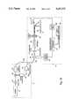
- FIG. 3is a block diagram illustration of electronic elements useful in the apparatus of FIGS. 1A and 1B;
- FIG. 4is a mechanical illustration of an alternative embodiment of the present invention wherein the scanning elements travel along a fixed base.
- FIGS. 1A and 1Billustrate two embodiments of the laser scanning apparatus of the present invention.
- the apparatuscomprises a typically stationary optical source system 10 for producing two laser beams, an exposure beam and a reference beam, and a beam delivery system 12 for delivering the two laser beams to the locations at which they act.
- the optical source systemcomprises a laser source 14, such as a He-Ne laser or an Argon laser, or any other suitable laser source, for producing a laser beam, an optional shutter 16 for preventing the laser beam from penetrating the beam delivery system 12 when no laser light is necessary, and a beam splitter 18 for splitting the laser beam into two laser beams, a reference beam and an exposure beam.
- a laser source 14such as a He-Ne laser or an Argon laser, or any other suitable laser source
- an optional shutter 16for preventing the laser beam from penetrating the beam delivery system 12 when no laser light is necessary
- a beam splitter 18for splitting the laser beam into two laser beams, a reference beam and an exposure beam.
- the exposure beamwill be utilized either to produce a pixel in an image to be plotted or to read a pixel in an image to be scanned and the reference beam will be utilized to track the location of the exposure beam on both the x- and y-axes of a scan line.
- the exposure and reference beamsare respectively transmitted to single-mode fiber optic lightguides 20a or 20b via fiber couplers 22 such as are known in the art.
- the laser beam emerging from a fiber tip of lightguide 20ais typically focussed or collimated into the acousto/optic modulator 24 by a first lens, such as a ball micro lens or a GRIN rod lens. After passing through the acousto/optic modulator 24, the modulated light is refocused into an entrance to a lightguide 20c by a second lens identical to the first.
- acousto/optic modulator 24is operative to turn on and off the transmission of the exposure beam in accordance with data signals received from a host computer 100.
- Fiber optic lightguides 20b and 20cbring the laser beams to the beam delivery system 12 which can be a traveling system as in FIG. 1A or a stationary system as in FIG. 1B. It will be appreciated that utilization of fiber optic lightguides 20 enables the stationary optical source system 10 to be located arbitrarily far away from the beam delivery system 12 without a significant corresponding reduction in the intensity and the quality of the laser beam received by the system 12. It will further be appreciated that since single-mode fiber optic lightguides 20 carry a single propagation mode of light, the quality of the output beam does not vary when a lightguide 20 is bent.
- Beam delivery system 12comprises a piezoelectric actuator 30, such as those manufactured by Physics Instruments Gmbh of W. Germany, to which are attached, in any appropriate manner, exit fiber tips of lightguides 20b and 20c such that the fiber tips of both lightguides are simultaneously moved to a desired location.
- a piezoelectric actuator 30such as those manufactured by Physics Instruments Gmbh of W. Germany, to which are attached, in any appropriate manner, exit fiber tips of lightguides 20b and 20c such that the fiber tips of both lightguides are simultaneously moved to a desired location.
- the reference and exposure beamsare transmitted from the lightguides 20 as a combined beam 32 which remains combined until the latter is reflected onto a scanning medium 40 placed on either a moving carriage 41, as shown in the embodiment of FIG. 1B, or on a stationary base 43, as shown in the embodiment of FIG. 1A.
- the combined beam 32first enters a collimating lens 34. After the combined beam 32 is collimated, it is deflected to a rotating mirror 36 which subsequently deflects the combined beam 32 and projects it through an f-theta lens 38.
- the f-theta lens 38extends the focal lengths of the beams of the combined beam 32 toward the extremities of the arc, thus flattening most of the arc into a straight line. The final adjustment at the extreme ends of the line is accomplished electronically by increasing the intensity of the beam, described in more detail hereinbelow.
- the f-theta lens 38ensures sharp focus of the exposure beam on the scanning medium 40 and of the reference beam on a beam position detector (BPD) 42 along the entire scan line and substantially eliminates wide-angle distortion.
- BPDbeam position detector
- the BPD 42is operative to measure the location of the reference beam along the x- and y-axes of a scan line. The location data is then utilized in a closed feedback loop to maintain the exposure beam at the correct location on the scan line.
- a suitable BPD 42is described in European patent application 0,263,774, published Apr. 13, 1988 and owned by the assignee of the present invention. European patent application 0,263,774 is incorporated herein by reference. U.S. patent application Ser. No. 07/396,805 corresponds to this patent.
- both beamsare projected from the f-theta lens 38 toward the scanning medium 40 via a mirror 46. From mirror 46, the exposure beam is projected directly onto scanning medium 40, while the reference beam is reflected from a mirror 48 onto the BPD 42.
- the reference beamis projected directly onto the BPD 42 from the f-theta lens 38, while the exposure beam is reflected from a mirror 44 onto the scanning medium 40.
- a linear scanmust be executed along each scan line, where data modulation is synchronized with beam position.
- the distance between the centers of adjacent points and the point densitymust also be uniform along the scan line.
- the BPD 42tracks the reference beam along both the x- and y-axes of the scanning medium 40 and supplies the positional information to an electro-optical electronic control (El-Op) subsystem, described in more detail hereinbelow.
- El-Opelectro-optical electronic control
- Tracking and subsequent beam adjustment along the y-axisensures a linear scan.
- the reference beam position on the y-axisis fed into a closed loop that adjusts for variations due to air turbulence and structural limitations. The greatest variation is caused by the rotating mirror 36, since the physical characteristics of each facet differ one from another. Other factors include mirror wobble, vibrations, timing errors, and thermal variations in the system.
- the closed loopis explained hereinbelow.
- the position of the exposure beam along the x-axismust be constantly tracked for synchronization of data modulation with the exposure beam position and for the beam intensity adjustments along the scan line, necessary to ensure uniform point density.
- the exposure beam position on the x-axisis fed into the El-Op subsystem.
- the El-Op subsystemexecutes data modulation and stores, recalls and applies the intensity values for each point in the scan line.
- the position of the reference beam on the BPD 42corresponds to the position of the exposure beam on the scanning medium 40.
- tracking the reference beamis necessary and sufficient for locating the exposure beam on the medium 40.
- all necessary positional informationis supplied by tracking the reference beam.
- the exposure beam itselfis not tracked.
- the reference and exposure beam positions along a scan lineare adjusted together via adjustments of the location of the piezoelectric actuator 30.
- the closed feedback loopcomprises a BPD amplifier 50 for amplifying the signals received from the BPD 42, a closed loop real time servo control system 52 for producing control signals for the piezoelectric actuator 30 in response to the output of the BPD 42 and in a direction so as to maintain the position of the reference beam on the center of the y-axis of the BPD 42, and a piezoelectric actuator driver 54 for driving the piezoelectric actuator 30 in accordance with the control signals.
- the control system 52is typically designed to ensure an appropriately smooth and fast response of the piezoelectric actuator 30 in response to the control signals.
- the movement of the piezoelectric actuator 30moves the location of the exit ends of both fiber optic lightguides 20 thereby simultaneously effecting the change in the position of both the reference and exposure beams.
- the driver 54operates the piezoelectric actuator 30 around a central positive voltage, such as 50 V.
- each facet of the rotating mirror 36has its own variation from true.
- the closed loop system described hereinabovewill correct for the variation of each facet as the facet is being used for a scan line, where at the beginning of the scan line, the resultant error signal will be large.
- the closed loop systemwill operate to reduce the error signal to 0. As a new facet comes into use however, the error signal will again become large since the correction achieved for one facet is not necessarily proper for another facet.
- a pre-positioning signalcan optionally be sent from the host computer 100 or from a microprocessor 86 (shown in FIG. 3), at the beginning of each scan line to position the beams at a nominal position for the current facet.
- the pre-positioning signalis calculated by operating the apparatus of the present invention in an open-loop fashion and by measuring for each facet the error the reference beam makes with respect to the center of the BPD 42.
- the pre-positioning signal for each facetis the signal which will counteract the measured error for that facet.
- FIGS. 2A and 2Brespectively mechanically illustrate the apparatus of the present invention for the embodiments of FIGS. 1A and 1B.
- the stationary optical source system 10is located to the side of the beam delivery system 12 and the two systems are connected via lightguides 20.
- the piezoelectric actuator 30, collimating lens 34, rotating mirror 36, f-theta lens 38 and mirror 46are located on top of a moving housing 70.
- Moving housing 70moves along base 43 via motor means (not shown) which can be any suitable motor means, such as a rotary motor connected to moving housing 70 via a lead screw or a linear motor.
- the BPD 42 and the mirror 48are located inside housing 70, near base 43.
- the elements of the beam delivery systemare located in one plane on a stationary surface 72 under which moves carriage 41.
- carriage 41moves back and forth via motor means (not shown) which can be any suitable motor means such as those described hereinabove.
- FIGS. 2A and 2Balso illustrate the light path for the embodiments of FIGS. 1B and 1A respectively.
- the combined beam 32leaves the fiber optic lightguides 20 at the piezoelectric actuator 30 and is collimated by collimating lens 34.
- the collimated beamis deflected by the rotating mirror 36 to the f-theta lens 38.
- the combined beamis deflected to mirror 46 which deflects the beam downwards towards mirror 48 for the reference beam, marked 74, and towards the scanning medium 40 (not shown) for the exposure beam, marked 76.
- Mirror 48deflects the reference beam 74 towards the BPD 42.
- the combined beamis deflected to the mirror 44 which separates the reference beam from the exposure beam.
- the reference beam 74hits the BPD 42 while the exposure beam 76, hits the scanning medium 40 (not shown).
- FIG. 3illustrates, in block diagram form, the electrical and optical elements of the apparatus of the present invention, in a plotter embodiment, and the El-Op subsystem necessary for operating it.
- the BPD amplifier 50receives the voltage signals from the two sensors of the BPD 42, as described in European Application 0,263,744, and sums them. The resulting voltage, proportional to the beam intensity, is then converted to a clock (CLK) pulse. A voltage signal is generated every predetermined number of microns. Thus, a CLK pulse frequency with a predetermined pulse width is provided.
- a Strobe PLL board 80multiplies the CLK frequency into a pulse train of EXP CLK signals.
- Each EXP CLK signalis sent to a Data subsystem (not shown) from there to a Beam Control board.
- Each EXP CLK signalinstructs the Data subsystem to send data for one exposure point to the Beam Control board.
- the Beam Control boardexecutes data modulation and contains a correction LUT 120 that stores the intensity values along a scan line, necessary for correcting known mirror variations and known variations in the transmittance of the f-theta lens 38 due to the angle of the transmitted light.
- the corrections provided by the LUT 120help to produce a uniform light intensity on the scanning medium 40.
- the beam position detectorpulses, received through a data bus 102, advance the LUT addresses so that the proper laser intensity is applied along the entire line.
- Beam Control boardalso comprises a data board 112, such as a screen processor, which accepts data to be plotted from host computer 100. From the data board 112, the data is sent to a data expose board 110 which synchronizes and modulates the digital data signal and transforms it into an appropriate intensity level.
- a data board 112such as a screen processor, which accepts data to be plotted from host computer 100. From the data board 112, the data is sent to a data expose board 110 which synchronizes and modulates the digital data signal and transforms it into an appropriate intensity level.
- the data from the LUT 120 and the data expose board 110are sent to a modulator driver 114 which modulates a high frequency signal, typically 110 MHz, received from an oscillator 116 in accordance with the signals received from the data expose board 110 and the LUT 120.
- the data expose board 110indicates the required on or off state of the exposure beam 76 and the LUT 120 indicates the degree of intensity of the exposure beam 76.
- the signal produced by the modulator driver 114is amplified by an amplifier 118 and the amplified signal is then applied to the acousto/optic modulator 24 for modulation of the exposure beam.
- a light detector 60such as a PIN diode, is typically located near mirror 46 of the embodiment of FIG. 1A or near mirror 44 of the embodiment of FIG. 1B. For the purposes of clarity, light detector 60 is not shown in either FIG. 1A or 1B.
- the light detector 60produces a signal proportional to the intensity of the received light at either mirror 44 or mirror 46.
- the resultant signalis operated on by a light control system 84, comprising D/A converters, drivers and clock circuits, for controlling the light intensity of the exposure beam 76.
- System microprocessor 86stores the values used for the pre-positioning signal. It interfaces with the apparatus of the present invention via data bus 102.
- the optical components that lie in the optical path of the laser beamare responsible for directing the path of a modulated exposure beam of correct intensity to the scanning medium 40. These components are controlled by the E1-Op subsystem, which adjusts the beam position, modulates the beam and adjusts the beam intensity.
- the present inventioncan be applied to laser scanning systems which produce a single exposure beam using fiber optic lightguides.
- the single fiber-optic lightguideis moved via a piezoelectric actuator which is controlled by pre-positioning signals, as described hereinabove, rather than through feedback signals received as a result of a reference beam hitting a beam position detector.
- This alternative embodiment of the present inventionis shown in FIG. 4 for a laser beam scanning apparatus with a fixed base.
- the present inventioncan be applied to laser scanning systems which combine the reference and exposure beams into a single beam which can be transmitted via a single fiber optic lightguide.
Landscapes
- Physics & Mathematics (AREA)
- General Physics & Mathematics (AREA)
- Optics & Photonics (AREA)
- Engineering & Computer Science (AREA)
- Multimedia (AREA)
- Signal Processing (AREA)
- Facsimile Scanning Arrangements (AREA)
- Mechanical Light Control Or Optical Switches (AREA)
- Facsimile Heads (AREA)
- Mechanical Optical Scanning Systems (AREA)
- Laser Surgery Devices (AREA)
- Investigating Or Analysing Materials By Optical Means (AREA)
- Laser Beam Printer (AREA)
Abstract
Description
Claims (16)
Applications Claiming Priority (2)
| Application Number | Priority Date | Filing Date | Title |
|---|---|---|---|
| IL94308 | 1990-05-07 | ||
| IL94308AIL94308A0 (en) | 1990-05-07 | 1990-05-07 | Laser scanning apparatus |
Publications (1)
| Publication Number | Publication Date |
|---|---|
| US5247174Atrue US5247174A (en) | 1993-09-21 |
Family
ID=11061175
Family Applications (1)
| Application Number | Title | Priority Date | Filing Date |
|---|---|---|---|
| US07/691,228Expired - Fee RelatedUS5247174A (en) | 1990-05-07 | 1991-04-25 | Laser scanning apparatus having a scanning beam and a reference beam |
Country Status (7)
| Country | Link |
|---|---|
| US (1) | US5247174A (en) |
| EP (1) | EP0456355B1 (en) |
| JP (1) | JPH05100174A (en) |
| AT (1) | ATE131677T1 (en) |
| CA (1) | CA2041692A1 (en) |
| DE (1) | DE69115347T2 (en) |
| IL (1) | IL94308A0 (en) |
Cited By (23)
| Publication number | Priority date | Publication date | Assignee | Title |
|---|---|---|---|---|
| US5594556A (en)* | 1993-03-28 | 1997-01-14 | Scitex Corporation Ltd. | Scanner having a misalignment detector |
| GB2328039A (en)* | 1997-06-27 | 1999-02-10 | Speedring Systems Inc | Polygon scanner having a fluid film bearing and active correction of cross-scan and in-scan errors |
| US6091461A (en)* | 1997-08-14 | 2000-07-18 | Sony Corporation | Electronically self-aligning high resolution projection display with rotating mirrors and piezoelectric transducers |
| US6268944B1 (en) | 1998-02-19 | 2001-07-31 | Com Dev Limited | Free-space optical lasercom system |
| US20020064341A1 (en)* | 2000-11-27 | 2002-05-30 | Fauver Mark E. | Micro-fabricated optical waveguide for use in scanning fiber displays and scanned fiber image acquisition |
| WO2001097902A3 (en)* | 2000-06-19 | 2002-06-20 | Univ Washington | Medical imaging, diagnosis, and therapy using a scanning single optical fiber system |
| US20040151466A1 (en)* | 2003-01-24 | 2004-08-05 | Janet Crossman-Bosworth | Optical beam scanning system for compact image display or image acquisition |
| US20040254474A1 (en)* | 2001-05-07 | 2004-12-16 | Eric Seibel | Optical fiber scanner for performing multimodal optical imaging |
| US6845190B1 (en) | 2000-11-27 | 2005-01-18 | University Of Washington | Control of an optical fiber scanner |
| US7046266B1 (en)* | 1998-07-04 | 2006-05-16 | Laser Imaging Systems Gmbh & Co. Kg | Scanner system |
| US20060170930A1 (en)* | 2001-05-07 | 2006-08-03 | University Of Washington | Simultaneous beam-focus and coherence-gate tracking for real-time optical coherence tomography |
| US20070213618A1 (en)* | 2006-01-17 | 2007-09-13 | University Of Washington | Scanning fiber-optic nonlinear optical imaging and spectroscopy endoscope |
| US20070216908A1 (en)* | 2006-03-17 | 2007-09-20 | University Of Washington | Clutter rejection filters for optical doppler tomography |
| US20090028407A1 (en)* | 2005-11-23 | 2009-01-29 | University Of Washington | Scanning beam with variable sequential framing using interrupted scanning resonance |
| US7952718B2 (en) | 2007-05-03 | 2011-05-31 | University Of Washington | High resolution optical coherence tomography based imaging for intraluminal and interstitial use implemented with a reduced form factor |
| US8382662B2 (en) | 2003-12-12 | 2013-02-26 | University Of Washington | Catheterscope 3D guidance and interface system |
| US8396535B2 (en) | 2000-06-19 | 2013-03-12 | University Of Washington | Integrated optical scanning image acquisition and display |
| US20130077133A1 (en)* | 2006-03-22 | 2013-03-28 | Jun Tanaka | Image reading apparatus, shading correction method therefor, and program for implementing the method |
| US8840566B2 (en) | 2007-04-02 | 2014-09-23 | University Of Washington | Catheter with imaging capability acts as guidewire for cannula tools |
| US9161684B2 (en) | 2005-02-28 | 2015-10-20 | University Of Washington | Monitoring disposition of tethered capsule endoscope in esophagus |
| US9561078B2 (en) | 2006-03-03 | 2017-02-07 | University Of Washington | Multi-cladding optical fiber scanner |
| WO2020115110A1 (en)* | 2018-12-07 | 2020-06-11 | Trumpf Laser Gmbh | Laser processing machine having a wobble scanner |
| US20220413296A1 (en)* | 2021-06-25 | 2022-12-29 | Meta Platforms Technologies, Llc | Offsetting image light aberration due to waveguide movement in display assemblies |
Families Citing this family (2)
| Publication number | Priority date | Publication date | Assignee | Title |
|---|---|---|---|---|
| DE4225828A1 (en)* | 1992-08-05 | 1994-02-10 | Hoechst Ag | Laser exposure device for printing forms to be exposed imagewise |
| US8485669B2 (en)* | 2010-01-29 | 2013-07-16 | Nec Display Solutions, Ltd. | Projector and illumination apparatus for same |
Citations (9)
| Publication number | Priority date | Publication date | Assignee | Title |
|---|---|---|---|---|
| US4307409A (en)* | 1980-05-27 | 1981-12-22 | Sperry Corporation | Multi-aperture, feedback system for a laser scanner |
| US4523093A (en)* | 1981-09-03 | 1985-06-11 | Excellon Industries | Scanning beam reference and read system |
| EP0263774A2 (en)* | 1986-10-07 | 1988-04-13 | Scitex Corporation Ltd. | Scanner |
| US4739162A (en)* | 1987-02-04 | 1988-04-19 | General Electric Company | Laser beam injecting system |
| US4746180A (en)* | 1984-10-30 | 1988-05-24 | Dr. Ing. Rudolf Hell Gmbh | Device for light transmission |
| US4834520A (en)* | 1987-01-07 | 1989-05-30 | Scitex Corporation Ltd. | Device for stabilization of beam intensity distribution in laser scanners |
| US4866464A (en)* | 1988-10-20 | 1989-09-12 | The Gerber Scientific Instrument Company | Method and apparatus for generating a scan timing signal with diffuser and detector array |
| IL78216A (en)* | 1985-03-29 | 1990-01-18 | Grumman Aerospace Corp | Systems and methods for processing optical correlator memory devices |
| WO1990001716A1 (en)* | 1988-08-01 | 1990-02-22 | Commonwealth Scientific And Industrial Research Organisation | Confocal microscope |
- 1990
- 1990-05-07ILIL94308Apatent/IL94308A0/ennot_activeIP Right Cessation
- 1991
- 1991-04-16EPEP91303375Apatent/EP0456355B1/ennot_activeExpired - Lifetime
- 1991-04-16ATAT91303375Tpatent/ATE131677T1/ennot_activeIP Right Cessation
- 1991-04-16DEDE69115347Tpatent/DE69115347T2/ennot_activeExpired - Fee Related
- 1991-04-25USUS07/691,228patent/US5247174A/ennot_activeExpired - Fee Related
- 1991-05-02CACA002041692Apatent/CA2041692A1/ennot_activeAbandoned
- 1991-05-07JPJP3101390Apatent/JPH05100174A/enactivePending
Patent Citations (10)
| Publication number | Priority date | Publication date | Assignee | Title |
|---|---|---|---|---|
| US4307409A (en)* | 1980-05-27 | 1981-12-22 | Sperry Corporation | Multi-aperture, feedback system for a laser scanner |
| US4523093A (en)* | 1981-09-03 | 1985-06-11 | Excellon Industries | Scanning beam reference and read system |
| US4746180A (en)* | 1984-10-30 | 1988-05-24 | Dr. Ing. Rudolf Hell Gmbh | Device for light transmission |
| IL78216A (en)* | 1985-03-29 | 1990-01-18 | Grumman Aerospace Corp | Systems and methods for processing optical correlator memory devices |
| EP0263774A2 (en)* | 1986-10-07 | 1988-04-13 | Scitex Corporation Ltd. | Scanner |
| US4931637A (en)* | 1986-10-07 | 1990-06-05 | Scitex Corporation Ltd. | Scanner utilizing a particular light guide |
| US4834520A (en)* | 1987-01-07 | 1989-05-30 | Scitex Corporation Ltd. | Device for stabilization of beam intensity distribution in laser scanners |
| US4739162A (en)* | 1987-02-04 | 1988-04-19 | General Electric Company | Laser beam injecting system |
| WO1990001716A1 (en)* | 1988-08-01 | 1990-02-22 | Commonwealth Scientific And Industrial Research Organisation | Confocal microscope |
| US4866464A (en)* | 1988-10-20 | 1989-09-12 | The Gerber Scientific Instrument Company | Method and apparatus for generating a scan timing signal with diffuser and detector array |
Non-Patent Citations (8)
| Title |
|---|
| D. P. Jablonowski and J. Raamot, "Beam Deflection at High Accuracy and Precision", SPIE vol. 84, 1976. |
| D. P. Jablonowski and J. Raamot, Beam Deflection at High Accuracy and Precision , SPIE vol. 84, 1976.* |
| F. Bestenreiner et al., "Visibility and Correction of Periodic Interference Structures in Line-by-Line Recorded Images", J. of Appl. Phot. Eng. vol. 2, 1976. |
| F. Bestenreiner et al., Visibility and Correction of Periodic Interference Structures in Line by Line Recorded Images , J. of Appl. Phot. Eng. vol. 2, 1976.* |
| M. R. Smith, R. H. Burns, and R. C. Tsai, "Ultrahigh Resolution Graphic Data Terminal", SPIE vol. 200, 1979. |
| M. R. Smith, R. H. Burns, and R. C. Tsai, Ultrahigh Resolution Graphic Data Terminal , SPIE vol. 200, 1979.* |
| S. Bousky and L. Teeple, "Laser Recording Performance with Spatial Error Compensation". SPIE, vol. 53, 1973. |
| S. Bousky and L. Teeple, Laser Recording Performance with Spatial Error Compensation . SPIE, vol. 53, 1973.* |
Cited By (38)
| Publication number | Priority date | Publication date | Assignee | Title |
|---|---|---|---|---|
| US5594556A (en)* | 1993-03-28 | 1997-01-14 | Scitex Corporation Ltd. | Scanner having a misalignment detector |
| GB2328039A (en)* | 1997-06-27 | 1999-02-10 | Speedring Systems Inc | Polygon scanner having a fluid film bearing and active correction of cross-scan and in-scan errors |
| US5999302A (en)* | 1997-06-27 | 1999-12-07 | Speedring Systems, Inc. | Polygon scanner having a fluid film bearing and active correction of cross-scan and in-scan errors |
| US6091461A (en)* | 1997-08-14 | 2000-07-18 | Sony Corporation | Electronically self-aligning high resolution projection display with rotating mirrors and piezoelectric transducers |
| US6268944B1 (en) | 1998-02-19 | 2001-07-31 | Com Dev Limited | Free-space optical lasercom system |
| US7046266B1 (en)* | 1998-07-04 | 2006-05-16 | Laser Imaging Systems Gmbh & Co. Kg | Scanner system |
| US6975898B2 (en) | 2000-06-19 | 2005-12-13 | University Of Washington | Medical imaging, diagnosis, and therapy using a scanning single optical fiber system |
| US8396535B2 (en) | 2000-06-19 | 2013-03-12 | University Of Washington | Integrated optical scanning image acquisition and display |
| WO2001097902A3 (en)* | 2000-06-19 | 2002-06-20 | Univ Washington | Medical imaging, diagnosis, and therapy using a scanning single optical fiber system |
| US6856712B2 (en) | 2000-11-27 | 2005-02-15 | University Of Washington | Micro-fabricated optical waveguide for use in scanning fiber displays and scanned fiber image acquisition |
| US6845190B1 (en) | 2000-11-27 | 2005-01-18 | University Of Washington | Control of an optical fiber scanner |
| US20020064341A1 (en)* | 2000-11-27 | 2002-05-30 | Fauver Mark E. | Micro-fabricated optical waveguide for use in scanning fiber displays and scanned fiber image acquisition |
| US20040254474A1 (en)* | 2001-05-07 | 2004-12-16 | Eric Seibel | Optical fiber scanner for performing multimodal optical imaging |
| US20060170930A1 (en)* | 2001-05-07 | 2006-08-03 | University Of Washington | Simultaneous beam-focus and coherence-gate tracking for real-time optical coherence tomography |
| US7349098B2 (en) | 2001-05-07 | 2008-03-25 | University Of Washington | Simultaneous beam-focus and coherence-gate tracking for real-time optical coherence tomography |
| US7616986B2 (en) | 2001-05-07 | 2009-11-10 | University Of Washington | Optical fiber scanner for performing multimodal optical imaging |
| US7068878B2 (en) | 2003-01-24 | 2006-06-27 | University Of Washington | Optical beam scanning system for compact image display or image acquisition |
| US20040151466A1 (en)* | 2003-01-24 | 2004-08-05 | Janet Crossman-Bosworth | Optical beam scanning system for compact image display or image acquisition |
| US8382662B2 (en) | 2003-12-12 | 2013-02-26 | University Of Washington | Catheterscope 3D guidance and interface system |
| US9554729B2 (en) | 2003-12-12 | 2017-01-31 | University Of Washington | Catheterscope 3D guidance and interface system |
| US9226687B2 (en) | 2003-12-12 | 2016-01-05 | University Of Washington | Catheterscope 3D guidance and interface system |
| US9161684B2 (en) | 2005-02-28 | 2015-10-20 | University Of Washington | Monitoring disposition of tethered capsule endoscope in esophagus |
| US9872613B2 (en) | 2005-02-28 | 2018-01-23 | University Of Washington | Monitoring disposition of tethered capsule endoscope in esophagus |
| US8537203B2 (en) | 2005-11-23 | 2013-09-17 | University Of Washington | Scanning beam with variable sequential framing using interrupted scanning resonance |
| US20090028407A1 (en)* | 2005-11-23 | 2009-01-29 | University Of Washington | Scanning beam with variable sequential framing using interrupted scanning resonance |
| US20070213618A1 (en)* | 2006-01-17 | 2007-09-13 | University Of Washington | Scanning fiber-optic nonlinear optical imaging and spectroscopy endoscope |
| US9561078B2 (en) | 2006-03-03 | 2017-02-07 | University Of Washington | Multi-cladding optical fiber scanner |
| US20070216908A1 (en)* | 2006-03-17 | 2007-09-20 | University Of Washington | Clutter rejection filters for optical doppler tomography |
| US20130077133A1 (en)* | 2006-03-22 | 2013-03-28 | Jun Tanaka | Image reading apparatus, shading correction method therefor, and program for implementing the method |
| US8570611B2 (en)* | 2006-03-22 | 2013-10-29 | Canon Denshi Kabushiki Kaisha | Image reading apparatus, shading correction method therefor, and program for implementing the method |
| US8840566B2 (en) | 2007-04-02 | 2014-09-23 | University Of Washington | Catheter with imaging capability acts as guidewire for cannula tools |
| US7952718B2 (en) | 2007-05-03 | 2011-05-31 | University Of Washington | High resolution optical coherence tomography based imaging for intraluminal and interstitial use implemented with a reduced form factor |
| WO2020115110A1 (en)* | 2018-12-07 | 2020-06-11 | Trumpf Laser Gmbh | Laser processing machine having a wobble scanner |
| CN113165110A (en)* | 2018-12-07 | 2021-07-23 | 通快激光有限责任公司 | Laser processing machine with swinging scanner |
| US20220413296A1 (en)* | 2021-06-25 | 2022-12-29 | Meta Platforms Technologies, Llc | Offsetting image light aberration due to waveguide movement in display assemblies |
| US11719942B2 (en)* | 2021-06-25 | 2023-08-08 | Meta Platforms Technologies, Llc | Offsetting image light aberration due to waveguide movement in display assemblies using information from piezoelectric movement sensors |
| US20230324694A1 (en)* | 2021-06-25 | 2023-10-12 | Meta Platforms Technologies, Llc | Offsetting image light aberration due to waveguide movement in display assemblies |
| US12078810B2 (en)* | 2021-06-25 | 2024-09-03 | Meta Platforms Technologies, Llc | Offsetting image light aberration due to waveguide movement in display assemblies |
Also Published As
| Publication number | Publication date |
|---|---|
| JPH05100174A (en) | 1993-04-23 |
| IL94308A0 (en) | 1991-03-10 |
| EP0456355B1 (en) | 1995-12-13 |
| DE69115347T2 (en) | 1996-09-05 |
| ATE131677T1 (en) | 1995-12-15 |
| CA2041692A1 (en) | 1991-11-08 |
| EP0456355A2 (en) | 1991-11-13 |
| DE69115347D1 (en) | 1996-01-25 |
| EP0456355A3 (en) | 1992-09-23 |
Similar Documents
| Publication | Publication Date | Title |
|---|---|---|
| US5247174A (en) | Laser scanning apparatus having a scanning beam and a reference beam | |
| US4661699A (en) | Scanning beam control system and method with bi-directional reference scale | |
| US4931637A (en) | Scanner utilizing a particular light guide | |
| US4284994A (en) | Laser beam recorder | |
| JPS6345086B2 (en) | ||
| US4693555A (en) | Device for holding an imaging lens | |
| US5287125A (en) | Raster output scanner with process direction spot position control | |
| JPH0815839B2 (en) | Method and apparatus for improving accuracy of optical optical plotter | |
| JP3291341B2 (en) | Spot position control device | |
| US5321435A (en) | Multi-diameter record dot light scanning apparatus | |
| JP2696364B2 (en) | Monitor mechanism of scanning optical device | |
| JPH09218367A (en) | Scanning optical device | |
| JPH09325288A (en) | Multi-beam scanning device | |
| JPH09159948A (en) | Image forming device | |
| JP3299186B2 (en) | Optical scanning device having scanning position detection function | |
| JPH0829605B2 (en) | Color beam exposure control method | |
| JPS6156316A (en) | Laser printer | |
| Whitman et al. | Electronic f-theta correction for hologon deflector systems | |
| JP2001264658A (en) | Beam scanning device | |
| JPS6135328A (en) | Optical device for adjustement and oscillation wavelength measurement of laser diode unit | |
| JPS62201413A (en) | Laser drawing device | |
| JPS6145215A (en) | Laser printer | |
| JPS62294221A (en) | Focus position adjusting device for semiconductor laser optical system | |
| EP0704738A1 (en) | A facet inaccuracy compensation unit | |
| JPS6115118A (en) | laser printer |
Legal Events
| Date | Code | Title | Description |
|---|---|---|---|
| AS | Assignment | Owner name:SCITEX CORPORATION LTD., ISRAEL Free format text:ASSIGNMENT OF ASSIGNORS INTEREST.;ASSIGNOR:BERMAN, DOV;REEL/FRAME:005694/0404 Effective date:19910421 | |
| FEPP | Fee payment procedure | Free format text:PAYOR NUMBER ASSIGNED (ORIGINAL EVENT CODE: ASPN); ENTITY STATUS OF PATENT OWNER: LARGE ENTITY | |
| FPAY | Fee payment | Year of fee payment:4 | |
| AS | Assignment | Owner name:CREOSCITEX CORPORATION LTD., ISRAEL Free format text:ASSIGNMENT OF ASSIGNORS INTEREST;ASSIGNOR:SCITEX CORPORATION LTD.;REEL/FRAME:011245/0479 Effective date:20000829 | |
| FPAY | Fee payment | Year of fee payment:8 | |
| AS | Assignment | Owner name:CREO IL LTD., ISRAEL Free format text:CHANGE OF NAME;ASSIGNOR:CREOSCITEX CORPORATION LTD.;REEL/FRAME:012944/0274 Effective date:20020217 | |
| REMI | Maintenance fee reminder mailed | ||
| LAPS | Lapse for failure to pay maintenance fees | ||
| LAPS | Lapse for failure to pay maintenance fees | Free format text:PATENT EXPIRED FOR FAILURE TO PAY MAINTENANCE FEES (ORIGINAL EVENT CODE: EXP.); ENTITY STATUS OF PATENT OWNER: LARGE ENTITY | |
| STCH | Information on status: patent discontinuation | Free format text:PATENT EXPIRED DUE TO NONPAYMENT OF MAINTENANCE FEES UNDER 37 CFR 1.362 | |
| FP | Lapsed due to failure to pay maintenance fee | Effective date:20050921 |