US5247171A - Drift correction for fiberoptic pressure sensors - Google Patents
Drift correction for fiberoptic pressure sensorsDownload PDFInfo
- Publication number
- US5247171A US5247171AUS07/870,395US87039592AUS5247171AUS 5247171 AUS5247171 AUS 5247171AUS 87039592 AUS87039592 AUS 87039592AUS 5247171 AUS5247171 AUS 5247171A
- Authority
- US
- United States
- Prior art keywords
- pressure
- fiber
- diaphragm
- signal
- fiber optic
- Prior art date
- Legal status (The legal status is an assumption and is not a legal conclusion. Google has not performed a legal analysis and makes no representation as to the accuracy of the status listed.)
- Expired - Lifetime
Links
- 238000012937correctionMethods0.000titleclaimsabstractdescription19
- 239000000835fiberSubstances0.000claimsabstractdescription102
- 239000013307optical fiberSubstances0.000claimsabstractdescription39
- 230000007774longtermEffects0.000claimsabstractdescription3
- 230000003287optical effectEffects0.000claimsdescription10
- 230000000737periodic effectEffects0.000claimsdescription9
- 238000001514detection methodMethods0.000claimsdescription8
- 238000012935AveragingMethods0.000claimsdescription7
- 238000012545processingMethods0.000claimsdescription7
- 238000005070samplingMethods0.000claims1
- 238000000034methodMethods0.000abstractdescription18
- 238000005253claddingMethods0.000abstractdescription15
- 230000006872improvementEffects0.000abstractdescription4
- 230000002123temporal effectEffects0.000abstractdescription3
- 238000001914filtrationMethods0.000abstract1
- 238000003825pressingMethods0.000abstract1
- 238000005452bendingMethods0.000description14
- 230000000694effectsEffects0.000description7
- 230000008859changeEffects0.000description6
- 230000005693optoelectronicsEffects0.000description6
- 238000010586diagramMethods0.000description4
- 239000000463materialSubstances0.000description3
- 238000005259measurementMethods0.000description3
- 230000001902propagating effectEffects0.000description3
- 230000004044responseEffects0.000description3
- 239000004593EpoxySubstances0.000description2
- VYPSYNLAJGMNEJ-UHFFFAOYSA-NSilicium dioxideChemical compoundO=[Si]=OVYPSYNLAJGMNEJ-UHFFFAOYSA-N0.000description2
- GWEVSGVZZGPLCZ-UHFFFAOYSA-NTitan oxideChemical compoundO=[Ti]=OGWEVSGVZZGPLCZ-UHFFFAOYSA-N0.000description2
- 238000013459approachMethods0.000description2
- 230000008901benefitEffects0.000description2
- 230000001419dependent effectEffects0.000description2
- 238000005516engineering processMethods0.000description2
- 239000012528membraneSubstances0.000description2
- 229910052751metalInorganic materials0.000description2
- 239000002184metalSubstances0.000description2
- 239000011358absorbing materialSubstances0.000description1
- 238000010521absorption reactionMethods0.000description1
- 230000003213activating effectEffects0.000description1
- 230000005540biological transmissionEffects0.000description1
- 230000036772blood pressureEffects0.000description1
- 238000009530blood pressure measurementMethods0.000description1
- 238000006243chemical reactionMethods0.000description1
- 230000006835compressionEffects0.000description1
- 238000007906compressionMethods0.000description1
- 239000000356contaminantSubstances0.000description1
- 238000005314correlation functionMethods0.000description1
- 238000013461designMethods0.000description1
- 239000003989dielectric materialSubstances0.000description1
- 230000009977dual effectEffects0.000description1
- 230000007613environmental effectEffects0.000description1
- 238000012625in-situ measurementMethods0.000description1
- 238000010348incorporationMethods0.000description1
- 238000012986modificationMethods0.000description1
- 230000004048modificationEffects0.000description1
- 239000002245particleSubstances0.000description1
- 238000009428plumbingMethods0.000description1
- 230000001681protective effectEffects0.000description1
- 230000035945sensitivityEffects0.000description1
- 235000012239silicon dioxideNutrition0.000description1
- 239000000377silicon dioxideSubstances0.000description1
- 230000006641stabilisationEffects0.000description1
- 238000011105stabilizationMethods0.000description1
- 230000036962time dependentEffects0.000description1
- 239000004408titanium dioxideSubstances0.000description1
- 230000001131transforming effectEffects0.000description1
Images


Classifications
- G—PHYSICS
- G01—MEASURING; TESTING
- G01L—MEASURING FORCE, STRESS, TORQUE, WORK, MECHANICAL POWER, MECHANICAL EFFICIENCY, OR FLUID PRESSURE
- G01L9/00—Measuring steady of quasi-steady pressure of fluid or fluent solid material by electric or magnetic pressure-sensitive elements; Transmitting or indicating the displacement of mechanical pressure-sensitive elements, used to measure the steady or quasi-steady pressure of a fluid or fluent solid material, by electric or magnetic means
- G01L9/0041—Transmitting or indicating the displacement of flexible diaphragms
- G01L9/0076—Transmitting or indicating the displacement of flexible diaphragms using photoelectric means
- G01L9/0077—Transmitting or indicating the displacement of flexible diaphragms using photoelectric means for measuring reflected light
- A—HUMAN NECESSITIES
- A61—MEDICAL OR VETERINARY SCIENCE; HYGIENE
- A61B—DIAGNOSIS; SURGERY; IDENTIFICATION
- A61B5/00—Measuring for diagnostic purposes; Identification of persons
- A61B5/02—Detecting, measuring or recording for evaluating the cardiovascular system, e.g. pulse, heart rate, blood pressure or blood flow
- A61B5/021—Measuring pressure in heart or blood vessels
- A61B5/0215—Measuring pressure in heart or blood vessels by means inserted into the body
- A61B5/02154—Measuring pressure in heart or blood vessels by means inserted into the body by optical transmission
- G—PHYSICS
- G01—MEASURING; TESTING
- G01L—MEASURING FORCE, STRESS, TORQUE, WORK, MECHANICAL POWER, MECHANICAL EFFICIENCY, OR FLUID PRESSURE
- G01L27/00—Testing or calibrating of apparatus for measuring fluid pressure
- G01L27/002—Calibrating, i.e. establishing true relation between transducer output value and value to be measured, zeroing, linearising or span error determination
- G01L27/005—Apparatus for calibrating pressure sensors
Definitions
- This inventionrelates to improvements in fiber optic sensor systems, and in particular, to techniques for reducing bending and connector instabilities in intensity-encoded fiber optic sensors, as well as temporal drift correction for fiber optic pressure sensors.
- Optical fiber sensing systemshave found applications in many environments. For example, the measurement of intravascular blood pressure of human patients has been accomplished using equipment manufactured by the present Assignee, FiberOptic Sensor Technologies, Inc. (FST), in which a diaphragm at the fiber sensing tip deforms in response to a pressure differential, thus modulating through reflection the light signals sent through the fiber. Changes in the distance between a deformed diaphragm and the optical fiber end, and the diaphragm shape, modulate the amplitude of light that is reflected back into the optical fiber. Accordingly, the intensity of the returned light signal is related to the pressure acting on the sensing tip.
- FSTFiberOptic Sensor Technologies, Inc.
- connector instabilitieswhich result from imperfect alignment between the transmitting and receiving fibers, have a large effect on signal attenuation in short fibers by erratically transforming the mode distribution within the receiving fiber, with the result that axial modes in the transmitting fiber may become higher-order modes in the receiving fiber and vice versa.
- a two-centimeter bend in a 100-micron fibermay result in up to several percentage points of change in transmitted intensity.
- other time-dependent errorsmay be introduced by temperature-induced changes in fiber transmissivity.
- the present inventionseeks to minimize these sources of error by using specially-placed mode filters and strippers to filter the transmitted and received light signals to remove most cladding and higher-order core modes.
- the first-mentioned embodiment of the present inventionemploys mode strippers and mode filters to remove unwanted higher-order core and cladding modes.
- Mode filtersconsist of a fiber deformer which forms periodic bends in the encapsulated optical fiber. The periodic bends in the fiber, usually having radii of curvature on the order of several millimeters, remove the unwanted higher-order modes by effectively varying the incident angle of light passing through the fiber in parts of the bends, allowing many of the higher-order modes to simply pass through the fiber rather than undergo total internal reflection.
- Mode strippersrely on a buffer doped with an optically-opaque material over a short distance to remove modes which propagate in the fiber's cladding.
- the first embodiment of the present inventionselectively places them in a novel fashion in the connectors between the sensor ferrule and the optical source, as well as in the sensor ferrule itself, to remove the unwanted higher-order core and cladding modes at the source of their generation.
- Another technique to reduce connector instabilities incorporated in embodiments of the present inventionis the use of an angle polish on one of the optical fibers in the source-sensor connector. In this technique, one of the fibers is cut at an angle to its normal, while the other end of the fiber remains flat.
- the angle polishwhen applied to one of the fibers, ensures that both fibers sought to be connected will remain separated by more than a quarter wavelength over most of their faces, thus preventing unwanted interference effects from reflections at both fiber ends.
- Such an angle polishalso acts as a filter for removing some additional higher-order modes in the source fiber.
- Another important technique of the present invention for reducing errors associated with bending, connector, and time-varying transmissivity instabilities in pressure-measuring sensorsconsists of periodically recalibrating the sensor by externally applying a pressure differential to the sensing diaphragm sufficient to cause the diaphragm to contact protrusions placed on the sensor ferrule.
- the difference of the system voltage obtained during each recalibration, which is proportional to the reflected light intensity recorded by photodetectors, and the system voltage recorded during an initial calibration run,is subtracted from the measured system voltage as a constant correction term.
- the tip of the sensor ferruleis provided with one or more protrusions which contact the diaphragm during the recalibration event.
- This contact eventmay be identified by the signal-processing apparatus by either lock-in detection, autocorrelation, or averaging techniques.
- the first of theserelies on the superposition of a high-frequency pressure signal with an associated dither frequency on the vacuum ramp applied to the diaphragm during the calibration operation; the signal processing apparatus examines the component of the voltage at the selected frequency, and observes the contact event as a change in signal amplitude at that frequency.
- the autocorrelation techniquecompares two temporally-successive pressure waveforms for significant changes; the contact event is identified when the second differs materially in functional form from the first.
- the final techniquerelies on averaging the measured system voltage values derived during calibration over pressure, identifying the contact event and associated correction term when the standard deviation in the averaged voltage values drops below a preselected number.
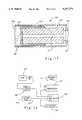
- FIG. 1is a block diagram of a system sensing a chosen physical parameter in accordance with the present invention
- FIG. 2is a cross-section of a stepped-index optical fiber showing in diagramatic form various modes of light propagation through the optical fiber relevant to the present invention
- FIG. 3is a schematic diagram showing the position of a fiber connector of the present invention incorporating an integral mode filter
- FIG. 4is a cross-section of a fiber connector of the present invention.
- FIG. 5is a cross-section of a mode stripper of the present invention incorporated at a sensor tip
- FIG. 6is a cross-section of a mode filter adjacent to a sensor tip of the present invention.
- FIG. 7is a schematic drawing showing the location of a mode filter in one embodiment of the present invention.
- FIG. 8is a schematic drawing showing the location of a mode filter in another embodiment of the present invention.
- FIG. 9is a cross-section of a fiber connector incorporating an angle polish of the present invention.
- FIG. 10is an enlargement of the cross-section of the fiber shown in FIG. 9 incorporating an angle polish of the present invention.
- FIG. 11is a cross-section showing the connection of two fiber connectors containing an angle polish of the present invention.
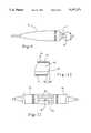
- FIG. 12is a cross-section of a sensing tip of yet another embodiment of the present invention containing two protrusions for engaging a pressure-sensing diaphragm;
- FIG. 13is a schematic diagram showing the arrangement of the vacuum means of the present invention.
- FIG. 14is a graph of sensed voltage vs. applied vacuum pressure showing the characteristic signature of a contact event relied on in one embodiment of the present invention in identifying a contact event between the sensing tip's diaphragm and the protrusions in the sensor tip;
- FIG. 15is a graph of sensed voltage vs. applied vacuum pressure showing a second method employed in the present invention of identifying a contact event between the sensing tip's diaphragm and the protrusions.
- This inventionis directed to two areas of improvement in intensity-modulated fiber optic sensing systems. For the sake of clarity, the various aspects of this invention will be discussed in separate sections identified by descriptive headings.
- FIG. 1A generalized fiber optic sensing system is shown in FIG. 1 and is generally designated there by reference number 10.
- System 10includes fiber optic cable 12 which has a sensing tip 14 at its terminal end.
- Optical fiber 11passes through ferrule 13 to which it is bonded or interference fit.
- Cylinder 15surrounds ferrule 13.
- Deflectable diaphragm cap 16has a center membrane portion which deforms in response to pressure differentials across it, and thus changes the amplitude of light launched into optical filament 11 at the opposite end of the filament which is returned back into the filament.
- pressurehas been chosen to be the physical parameter to be measured by the fiber optic sensor, but the in-fiber correction scheme of the present invention will work equally well for any physical parameter sought to be measured by an intensity-encoded fiber-optic sensing system.
- a vent passage 30is provided to maintain the fiber side of the diaphragm cap 16 at a desired pressure during in situ measurement or calibration.
- the features of this inventionare also applicable to sensing systems which do not employ these wavelength referencing features, however.
- Opto-electronic interface 18contains the optical sources, LEDs 20 and 22, each emitting light in distinct wavelength bands; photodetectors 26 and 28; and a coupler, not shown, for launching light from the LEDs into optical filament 11 and directing the returned signals to be incident on the photodetectors. Some of the light from the LEDs is directed to fall on photodetector 26, which provides a source intensity reference.
- the output signals from opto-electronic interface 18are converted into digital form by A/D converter 29 and transmitted to digital signal processing (DSP) module 34. The two signals are related to the intensity of the returned signals of the two LEDs. DSP module 34 and the associated host microprocessor control the operation of LEDs 20 and 22 and perform real-time computations and conversions. The outputs of module 34 are real-time readings of the physical parameter chosen, in this case pressure.
- the deflection of the diaphragm cap 16is measured using the dual-wavelength reference technique described in U. S. Pat. No. 4,924,870, in which the light signal from LED 20 is reflected by filter layer 17, whereas the light pulse from LED 22 passes through the filter to be modulated by diaphragm cap 16.
- the use of the referencing wavelength from LED 20 in this approachpermits some compensation for environmental effects on the system such as vibration, connector instability, bending effects, and some of the sensing tip irregularities.
- FIG. 2shows an optical fiber used in the present invention to convey intensity-encoded light signals from opto-electronic interface 18 to sensing tip 14.
- the fiberconsists of two different optical materials, a core 35 and a cladding 36, having different indices of refraction.
- the cladding's index of refractionis chosen to be lower than the core's to facilitate the total internal reflection of most of the light propagating within the fiber. Since the diameter of the optical fiber is considerably greater than the wavelength of the relevant light, many different propagation conditions (modes) are possible within the fiber.
- axial modes 37which propagate straight through the fiber while undergoing very few or no reflections
- low-order modes 38which are characterized by a small launching angle and relatively few reflections per unit length
- high-order modes 39characterized by a high launching angle into the fiber and a relatively large number of reflections per unit length
- optical fiber 11Such bending of optical fiber 11 locally varies the incident angle of many of these high-order (, modes 39 sufficiently to allow them to exceed the fiber's critical angle and escape the fiber core entirely after a few partial reflections.
- the presence of a significant fraction of high-order modes in the reflected signal and the consequent loss of many of these modesthus makes the total intensity of the signal reflected from sensing tip 14 strongly dependent on fiber bending conditions.
- the correction apparatus of the present inventiontherefore seeks to remove most of the high-order modes from optical fiber 11. While a stepped-index fiber has been chosen for the purposes of illustration, it should be kept in mind that the discussion also applies to a graded-index fiber incorporating a core with a variable index of refraction.
- FIG. 3is a schematic diagram showing one possible placement of the in-line connectors in a fiber optic sensor of the present invention.
- Opto-electronic interface 18contains an in-line connector 31 housing optical fiber 11, which mates with another in-line connector 40, containing optical fiber 11 and connected to ferrule 13.
- a connector 40 incorporating an integral mode filter of the present inventionis shown in FIG. 4.
- Connector 40a conventional fiber connector, contains an optical fiber 42 in its center and can be plugged into a similar fiber connector containing a second optical fiber to optically couple the fibers, as shown in FIG. 3.
- Connector 40incorporates an integral mode filter 44 within its body.
- Mode filter 44consists of an element which periodically deforms center fiber 42, such as a plastic or metal tube incorporating a periodic set of bends. This tube completely encloses center fiber 42, causing it to assume the periodic bend form itself.
- the periodic bends 46 in mode filter 40vary the angle of incidence for light reaching the outer interface of the fiber core 46 at these bends 46, and all modes propagating in the fiber with an angle greater than the fiber's critical angle will be transmitted out of the fiber within a few reflections rather than undergo total internal reflection and continue propagation. Since these bends locally increase the angle of incidence of light striking the outside of the fiber core 46 at certain points in the fiber, the periodic bends 46 result in differentially greater attenuation of higher-order modes, since the angles of incidence for these modes are closer to the critical angle before reaching the mode filter 42. Cladding modes, which are modes propagating within fiber cladding 36, are removed from the light signal in an analogous way by the bends 46 of the mode filter.
- the chosen number and radius of the bends 46depend on empirical factors such as the fiber diameter, launching condition from sources 20 and 22, and the numerical aperture of the fiber. Bend radii of a few millimeters are generally satisfactory for fiber diameters on the order of 100 micrometers.
- FIG. 5illustrates a mode stripper and mode filter incorporated directly into the sensor tip of the fiber optic sensor.
- In-ferrule mode filter 50is entirely contained within ferrule 13, as FIG. 5 shows.
- Ferrule 13 containing optical fiber 11includes compression ridges 51, which periodically deform fiber 11 within ferrule 13, creating bends 52. These bends 52 act as a mode filter, varying the local incident angle of light within the fiber in a completely analogous way to that of bends 46 in mode filter 44 and differentially removing higher-order and cladding modes.
- a mode stripper 54which is an approximately one-centimeter segment of cladding covered by a light-absorbing material, typically an epoxy which is optically black at the wavelengths used for the light signals. This mode stripper removes a substantial fraction of cladding modes through absorption.
- Mode filter 56consisting of a plastic or metal tube with periodic deformations, is connected to ferrule 13 at its rear face 58 and contains the portion of optical fiber immediately adjacent to ferrule 13, deforming it periodically.
- the portion of optical fiber 11 contained in ferrule 13contains a mode stripper 60, which is a one-centimeter length of fiber whose cladding is covered by an optically black epoxy, in an analogous way to that of mode stripper 54.
- optical fiber 11are already present immediately before the signal's reflection at diaphragm cap 16 and dielectric filter 17. Furthermore, reflection of the optical signal at diaphragm cap 16 also changes the signal's mode distribution, adding higher-order modes from nonparaxial reflections on the curved diaphragm.
- the mode filters 51 and 56 located within or adjacent to the sensor ferrule 13strongly attenuate these reflected higher-order modes, preventing them from substantially altering the strength of the received light signal through differential bending losses in optical fiber 11.
- the mode filters of the present inventionallow a substantial portion of low-order modes and a certain fraction of higher-order modes to pass through them.
- mode filter 62is incorporated into optical fiber 11 at a point between opto-electronic interface 18 and source connector 64, which connects to a similar connector containing a second length of fiber and the sensor ferrule, not shown. Placement of mode filter 62 in the location shown simplifies the design of ferrule 13 and allows thermal stabilization of mode filter 62 to eliminate temperature-induced drift in the sensing signal.
- the mode filter 66 shown in FIG. 8is located on the source side of fiber optic sensor 10. Mode filter 66 is located between in-line connectors 68 and 70, which connect optical fiber 11 to connector 72, which joins a fourth connector, not shown, containing an optical fiber leading into sensor ferrule 13.
- FIGS. 9, 10, and 11Another embodiment of the fiber optic sensor of the present invention contains an angle polish applied to optical fiber 11, as illustrated in FIGS. 9, 10, and 11.
- Edge 76 of optical fiber 11, contained in connector 74is cut at an angle ⁇ to the fiber outer edge normal 78.
- the segment of optical fiber 11 contained in connector 74joins a flat segment of fiber contained in another connector 80, forming a wedge-shaped gap 82 between the two fiber halves.
- Angle ⁇is chosen to be the minimum angle compatible with a gap 82 having an average width greater than one-quarter of the wavelength of the light emitted from LEDs 20 and 22. Such a requirement results in values for of ⁇ of approximately 5 degrees.
- Gap 82prevents undesirable interference effects from boundary reflections at the interfaces where the halves of optical fiber 11 join in connectors 74 and 80.
- these prior art angle polisheshave been used to minimize specular reflections between fibers rather than prevent unwanted interference effects; consequently, the angle ⁇ chosen for these prior-art polishes has normally been approximately 10 degrees or greater rather than the small values used in the present invention.
- the use of angles substantially greater than five degrees in the present inventionwould result in unacceptable losses from beam divergence as well as the introduction of unwanted higher-order modes into the light signal by off-axis refraction of the signal at angled surface 76.
- Sensing tip 100is connected to fiber optic cable 112, which contains optical fiber 111 and a vacuum passage 114 connected to a system vacuum port.
- Sensing tip 100includes optical fiber 111, which passes through ferrule 113.
- Cylinder 115partially surrounds ferrule 113.
- Deflectable diaphragm cap 116has a membrane portion which deforms in response to pressure differentials across it, changing the amplitude of light launched into optical filament 111 which is returned back into the filament.
- a protective cover 118protects diaphragm cap 116 and ferrule 113 from direct exposure to particles or other contaminants.
- Ferrule 113also contains two small hermispherical surface deformations 120 at its terminal end facing diaphragm cap 116.
- FIG. 13A plumbing schematic for the vacuum means in the fiber optic sensor is shown in FIG. 13.
- One end of vacuum port 122is connected to vacuum passage 114, which communicates with sensor ferrule 113 and the inner surface of diaphragm 116 facing the ferrule.
- the other end of vacuum port 122is connected to vacuum line 124, which is connected to control valve 126.
- Control valve 126allows vacuum port 122 to communicate with restricter 128, check valve 130 and vacuum pump 132.
- Transducer 134is connected across and measures the vacuum pressure in line 124.
- Vacuum pump 132draws a vacuum on vacuum port 122 through check valve 130 and control valve 126.
- Check valve 130acts as a volume reservoir, allowing the entire vacuum system and fiber optic sensor tip 100 to be maintained at an almost constant pressure over a desired sample time interval.
- the drift correction systemoperates by applying a time-varying level of vacuum through pump 132, check valve 130, control valve 126, vacuum port 122, and vacuum passage 114, to the inner surface of the diaphragm cap 116.
- This vacuumcauses diaphragm cap 116 to be displaced toward and eventually contact surface protrusions 120. It is important to note that although the physiological pressure waveform acting on the outer surface of diaphragm 116 is constantly changing and cannot be exactly measured during the calibration event, diaphragm 116 will always contact surface deformations 120 at a fixed pressure differential between the outer and inner surfaces.
- the inventionaccomplishes drift correction by activating the vacuum pump either periodically or on demand from the operator.
- the frequency of on-demand recalibrationis strongly dependent on the desired accuracy in the system as well as the degree of accuracy with which the contact voltage V c can be determined. In general, the lower the desired level of accuracy and the less accurately V c can be determined by DSP 34, the less frequently the user will wish to perform recalibration.
- the recalibration operationresults in the generation of a time-varying system error term V e , which is subtracted from all subsequent values of the measured signal until the next recalibration to produce an output signal voltage V out satisfying
- V m (t)is the measured value for voltage at time t.
- V c (O)is the value of the voltage signal at the contact event derived from an initial calibration.
- FIG. 14shows a typical relationship between pressure and output voltage V m from A/D converter 29.
- signal measured voltageis indicated on the vertical axis
- differential pressure across diaphragm cap 16is indicated on the horizontal axis.
- Graph 140shows the functional form of the output signal. Contact of diaphragm cap 16 with protrusions 120 is clearly indicated on the graph at (V c ,p c ); the characteristic form of the output signal at (V c ,p c ) is shown at 142.
- a technique relied on by the signal processing apparatus in one embodiment of the present invention to determine the contact eventis lock-on detection.
- the lock-in detection methodinvolves applying a vacuum to the inner surface of diaphragm 116 which has the functional form of a linear ramp in pressure and time with a superimposed high-frequency dither.
- the frequency of the superimposed waveformmust be chosen to be above the physiological frequencies of interest in the system to minimize physiological noise.
- the dithering frequencyis chosen to be over 50 Hertz.
- a lock-in amplifier in DSP 34operates on the output voltage signal from A/D converter 29. This lock-in amplifier examines the component of the voltage signal from the reflected light at the dithering frequency for large amplitude changes.
- the lock-in amplifieridentifies the contact event by its identification of a large amplitude change at that frequency.
- the associated output signal and pressure values V c and p c associated with the contact eventare simply those indicated by A/D converter 29 and pressure transducer 134 at the contact event. If a relatively long time interval is used between successive recalibrations, the lock-in detection may be performed several times and the average value of the contact voltage and pressure may be used to obtain a more accurate correction.
- a second technique for detecting the contact eventinvolves the use of waveform comparison.
- This techniqueinvolves the application of a vacuum by pump 132 to the inner surface of diaphragm cap 116; as this vacuum is being applied, DSP apparatus 34 stores two successive output waveforms over a chosen sample interval; an autocorrelation apparatus compares the successive waveforms by a technique such as subtracting one from the other to form a difference function or using a correlation function such as ##EQU1## where a t is the time-series representation of the first waveform and r t is the time-series representation of the second waveform.
- the function ⁇ armeasures the functional similarity of the two waveforms as a function of time shift ⁇ ; if ⁇ ar is suitably normalized, ⁇ ar , (O) will become quite small a the contact event as the two waveforms become more and more dissimilar. In the absence of a contact event, successive pressure waveforms will have approximately the same functional form since their underlying physiological components are roughly invariant if the sample interval is chosen to be long enough. At the contact event, however, the sudden change in the waveform, as indicated at 142, will cause the two stored waveforms to appreciably differ, and the autocorrelation unit will identify this difference and thereby detect the contact event, providing a value for v c for use in the error equation.
- a third technique for detecting the contact eventinvolves the use of an averaging technique.
- Such a techniqueinvolves averaging successive voltage values over many applied pressures, as illustrated in FIG. 15, which is a graph of measured signal voltage for various values of applied pressure during the calibration operation.
- Averaging means in DSP module 34averages successive values of V m , which is plotted at 150, as increasing vacuum levels are applied by vacuum pump 132.
- V cthe value of the signal voltage at the contact event.
- the resulting value of V c (t)is then used in the error equation to calculate V e (T) and subsequent values of V out .
Landscapes
- Health & Medical Sciences (AREA)
- Life Sciences & Earth Sciences (AREA)
- Physics & Mathematics (AREA)
- Cardiology (AREA)
- General Physics & Mathematics (AREA)
- Biomedical Technology (AREA)
- Medical Informatics (AREA)
- Physiology (AREA)
- Analytical Chemistry (AREA)
- Biophysics (AREA)
- Pathology (AREA)
- Engineering & Computer Science (AREA)
- Chemical & Material Sciences (AREA)
- Heart & Thoracic Surgery (AREA)
- Vascular Medicine (AREA)
- Molecular Biology (AREA)
- Surgery (AREA)
- Animal Behavior & Ethology (AREA)
- General Health & Medical Sciences (AREA)
- Public Health (AREA)
- Veterinary Medicine (AREA)
- Measuring Fluid Pressure (AREA)
- Computer And Data Communications (AREA)
- Mobile Radio Communication Systems (AREA)
- Pharmaceuticals Containing Other Organic And Inorganic Compounds (AREA)
Abstract
Description
V.sub.out (t)=V.sub.m (t)-V.sub.e -(T), (1)
V.sub.e (T)=V.sub.c (T)-V.sub.c (O), (2)
Claims (9)
Priority Applications (4)
| Application Number | Priority Date | Filing Date | Title |
|---|---|---|---|
| US07/870,395US5247171A (en) | 1992-04-17 | 1992-04-17 | Drift correction for fiberoptic pressure sensors |
| PCT/US1993/003480WO1993021652A1 (en) | 1992-04-17 | 1993-04-13 | Drift correction for fiberoptic pressure sensors |
| AU41071/93AAU670587B2 (en) | 1992-04-17 | 1993-04-20 | Verifying secret keys in a public-key cryptosystem |
| US08/314,613US5422478A (en) | 1992-04-17 | 1994-09-28 | Fiberoptic pressure sensor having drift correction means for insitu calibration |
Applications Claiming Priority (1)
| Application Number | Priority Date | Filing Date | Title |
|---|---|---|---|
| US07/870,395US5247171A (en) | 1992-04-17 | 1992-04-17 | Drift correction for fiberoptic pressure sensors |
Related Child Applications (1)
| Application Number | Title | Priority Date | Filing Date |
|---|---|---|---|
| US12118293AContinuation-In-Part | 1992-04-17 | 1993-09-14 |
Publications (1)
| Publication Number | Publication Date |
|---|---|
| US5247171Atrue US5247171A (en) | 1993-09-21 |
Family
ID=25355290
Family Applications (1)
| Application Number | Title | Priority Date | Filing Date |
|---|---|---|---|
| US07/870,395Expired - LifetimeUS5247171A (en) | 1992-04-17 | 1992-04-17 | Drift correction for fiberoptic pressure sensors |
Country Status (3)
| Country | Link |
|---|---|
| US (1) | US5247171A (en) |
| AU (1) | AU670587B2 (en) |
| WO (1) | WO1993021652A1 (en) |
Cited By (57)
| Publication number | Priority date | Publication date | Assignee | Title |
|---|---|---|---|---|
| US5422478A (en)* | 1992-04-17 | 1995-06-06 | Fiberoptic Sensor Technologies, Inc. | Fiberoptic pressure sensor having drift correction means for insitu calibration |
| US5437284A (en)* | 1993-12-30 | 1995-08-01 | Camino Laboratories, Inc. | System and method for in vivo calibration of a sensor |
| US5485741A (en)* | 1993-10-19 | 1996-01-23 | Medamicus, Inc. | Vacuum calibration method for an optical fiber pressure transducer |
| EP0719448A4 (en)* | 1993-09-14 | 1997-03-05 | Fiberoptic Sensor Tech | Fiberoptic pressure sensor having drift correcting means for in situ calibration |
| US5654539A (en)* | 1995-08-17 | 1997-08-05 | Vasamedics L.L.C. | Laser doppler optical sensor for use on a monitoring probe |
| US6094990A (en)* | 1998-06-30 | 2000-08-01 | Cooper Automotive Products, Inc. | Spark plug with concentric pressure sensor |
| US6204594B1 (en) | 1998-06-12 | 2001-03-20 | Cooper Automotive Products, Inc. | Spark plug with pressure sensor |
| US6237394B1 (en)* | 1999-02-25 | 2001-05-29 | Redwood Microsystems, Inc. | Apparatus and method for correcting drift in a sensor |
| US6321010B1 (en)* | 1999-08-30 | 2001-11-20 | Lucent Technologies Inc. | Optical microstructure and method of manufacture |
| US6425290B2 (en) | 2000-02-11 | 2002-07-30 | Rosemount Inc. | Oil-less differential pressure sensor |
| EP1059707A3 (en)* | 1999-06-03 | 2003-10-22 | TRW Inc. | High power optical fiber ribbon laser and amplifier |
| US7297166B2 (en) | 2003-06-25 | 2007-11-20 | Depuy Products, Inc. | Assembly tool for modular implants and associated method |
| US7582092B2 (en) | 2003-06-25 | 2009-09-01 | Depuy Products, Inc. | Assembly tool for modular implants and associated method |
| US7794407B2 (en) | 2006-10-23 | 2010-09-14 | Bard Access Systems, Inc. | Method of locating the tip of a central venous catheter |
| WO2011031945A1 (en)* | 2009-09-11 | 2011-03-17 | Alstom Grid | Master-slave fiber optic current sensors for differential protection schemes |
| US8388541B2 (en) | 2007-11-26 | 2013-03-05 | C. R. Bard, Inc. | Integrated system for intravascular placement of a catheter |
| US8388546B2 (en) | 2006-10-23 | 2013-03-05 | Bard Access Systems, Inc. | Method of locating the tip of a central venous catheter |
| US8437833B2 (en) | 2008-10-07 | 2013-05-07 | Bard Access Systems, Inc. | Percutaneous magnetic gastrostomy |
| US8478382B2 (en) | 2008-02-11 | 2013-07-02 | C. R. Bard, Inc. | Systems and methods for positioning a catheter |
| US8518050B2 (en) | 2007-10-31 | 2013-08-27 | DePuy Synthes Products, LLC | Modular taper assembly device |
| USD699359S1 (en) | 2011-08-09 | 2014-02-11 | C. R. Bard, Inc. | Ultrasound probe head |
| US8781555B2 (en) | 2007-11-26 | 2014-07-15 | C. R. Bard, Inc. | System for placement of a catheter including a signal-generating stylet |
| US8784336B2 (en) | 2005-08-24 | 2014-07-22 | C. R. Bard, Inc. | Stylet apparatuses and methods of manufacture |
| US8801693B2 (en) | 2010-10-29 | 2014-08-12 | C. R. Bard, Inc. | Bioimpedance-assisted placement of a medical device |
| US8849382B2 (en) | 2007-11-26 | 2014-09-30 | C. R. Bard, Inc. | Apparatus and display methods relating to intravascular placement of a catheter |
| USD724745S1 (en) | 2011-08-09 | 2015-03-17 | C. R. Bard, Inc. | Cap for an ultrasound probe |
| US8998919B2 (en) | 2003-06-25 | 2015-04-07 | DePuy Synthes Products, LLC | Assembly tool for modular implants, kit and associated method |
| US9095452B2 (en) | 2010-09-01 | 2015-08-04 | DePuy Synthes Products, Inc. | Disassembly tool |
| US9101495B2 (en) | 2010-06-15 | 2015-08-11 | DePuy Synthes Products, Inc. | Spiral assembly tool |
| US9125578B2 (en) | 2009-06-12 | 2015-09-08 | Bard Access Systems, Inc. | Apparatus and method for catheter navigation and tip location |
| US9211107B2 (en) | 2011-11-07 | 2015-12-15 | C. R. Bard, Inc. | Ruggedized ultrasound hydrogel insert |
| US9339206B2 (en) | 2009-06-12 | 2016-05-17 | Bard Access Systems, Inc. | Adaptor for endovascular electrocardiography |
| US9445734B2 (en) | 2009-06-12 | 2016-09-20 | Bard Access Systems, Inc. | Devices and methods for endovascular electrography |
| US9456766B2 (en) | 2007-11-26 | 2016-10-04 | C. R. Bard, Inc. | Apparatus for use with needle insertion guidance system |
| US9492097B2 (en) | 2007-11-26 | 2016-11-15 | C. R. Bard, Inc. | Needle length determination and calibration for insertion guidance system |
| US9498300B1 (en)* | 2015-07-30 | 2016-11-22 | Novartis Ag | Communication system for surgical devices |
| US9504578B2 (en) | 2011-04-06 | 2016-11-29 | Depuy Synthes Products, Inc | Revision hip prosthesis having an implantable distal stem component |
| US9521961B2 (en) | 2007-11-26 | 2016-12-20 | C. R. Bard, Inc. | Systems and methods for guiding a medical instrument |
| US9532724B2 (en) | 2009-06-12 | 2017-01-03 | Bard Access Systems, Inc. | Apparatus and method for catheter navigation using endovascular energy mapping |
| US9554716B2 (en) | 2007-11-26 | 2017-01-31 | C. R. Bard, Inc. | Insertion guidance system for needles and medical components |
| US9636031B2 (en) | 2007-11-26 | 2017-05-02 | C.R. Bard, Inc. | Stylets for use with apparatus for intravascular placement of a catheter |
| US9649048B2 (en) | 2007-11-26 | 2017-05-16 | C. R. Bard, Inc. | Systems and methods for breaching a sterile field for intravascular placement of a catheter |
| US9717545B2 (en) | 2007-10-30 | 2017-08-01 | DePuy Synthes Products, Inc. | Taper disengagement tool |
| US9839372B2 (en) | 2014-02-06 | 2017-12-12 | C. R. Bard, Inc. | Systems and methods for guidance and placement of an intravascular device |
| WO2017223350A1 (en)* | 2016-06-23 | 2017-12-28 | Intuitive Surgical Operations, Inc. | Removing light energy from a fiber cladding |
| US9901714B2 (en) | 2008-08-22 | 2018-02-27 | C. R. Bard, Inc. | Catheter assembly including ECG sensor and magnetic assemblies |
| US10046139B2 (en) | 2010-08-20 | 2018-08-14 | C. R. Bard, Inc. | Reconfirmation of ECG-assisted catheter tip placement |
| US10349890B2 (en) | 2015-06-26 | 2019-07-16 | C. R. Bard, Inc. | Connector interface for ECG-based catheter positioning system |
| US10449330B2 (en) | 2007-11-26 | 2019-10-22 | C. R. Bard, Inc. | Magnetic element-equipped needle assemblies |
| US10524691B2 (en) | 2007-11-26 | 2020-01-07 | C. R. Bard, Inc. | Needle assembly including an aligned magnetic element |
| US10639008B2 (en) | 2009-10-08 | 2020-05-05 | C. R. Bard, Inc. | Support and cover structures for an ultrasound probe head |
| US10751509B2 (en) | 2007-11-26 | 2020-08-25 | C. R. Bard, Inc. | Iconic representations for guidance of an indwelling medical device |
| US10820885B2 (en) | 2012-06-15 | 2020-11-03 | C. R. Bard, Inc. | Apparatus and methods for detection of a removable cap on an ultrasound probe |
| US10973584B2 (en) | 2015-01-19 | 2021-04-13 | Bard Access Systems, Inc. | Device and method for vascular access |
| US10992079B2 (en) | 2018-10-16 | 2021-04-27 | Bard Access Systems, Inc. | Safety-equipped connection systems and methods thereof for establishing electrical connections |
| US11000207B2 (en) | 2016-01-29 | 2021-05-11 | C. R. Bard, Inc. | Multiple coil system for tracking a medical device |
| US11103213B2 (en) | 2009-10-08 | 2021-08-31 | C. R. Bard, Inc. | Spacers for use with an ultrasound probe |
Families Citing this family (1)
| Publication number | Priority date | Publication date | Assignee | Title |
|---|---|---|---|---|
| CN112067194B (en)* | 2020-09-21 | 2021-05-25 | 黑龙江大学 | Device and method for dynamically calibrating optical fiber pressure sensor based on strain drop hammer |
Citations (8)
| Publication number | Priority date | Publication date | Assignee | Title |
|---|---|---|---|---|
| US4453218A (en)* | 1980-11-24 | 1984-06-05 | Oximetrix, Inc. | Signal filter method and apparatus |
| US4678902A (en)* | 1985-04-30 | 1987-07-07 | Metatech Corporation | Fiber optic transducers with improved sensitivity |
| US4711246A (en)* | 1986-09-02 | 1987-12-08 | Fiberoptic Sensor Technologies, Inc. | Fiber optic coupled pressure transducer using single fiber and method of fabrication |
| US4787396A (en)* | 1987-06-18 | 1988-11-29 | Fiberoptic Sensor Technologies, Inc. | Fiberoptic pressure transducer |
| US4856317A (en)* | 1988-05-02 | 1989-08-15 | Fiberoptic Sensor Technologies, Inc. | Vacuum calibration system and method for fiberoptic pressure transducer |
| US4886070A (en)* | 1988-05-11 | 1989-12-12 | Thermometrics, Inc. | Method of in vivo calibration of a pressure sensor |
| US4924870A (en)* | 1989-01-13 | 1990-05-15 | Fiberoptic Sensor Technologies, Inc. | Fiber optic sensors |
| US5146983A (en)* | 1991-03-15 | 1992-09-15 | Schlumberger Technology Corporation | Hydrostatic setting tool including a selectively operable apparatus initially blocking an orifice disposed between two chambers and opening in response to a signal |
Family Cites Families (4)
| Publication number | Priority date | Publication date | Assignee | Title |
|---|---|---|---|---|
| US5018196A (en)* | 1985-09-04 | 1991-05-21 | Hitachi, Ltd. | Method for electronic transaction with digital signature |
| US4933970A (en)* | 1988-01-19 | 1990-06-12 | Yeda Research And Development Company Limited | Variants of the fiat-shamir identification and signature scheme |
| US5146083A (en)* | 1990-09-21 | 1992-09-08 | The United States Of America As Represented By The Administrator Of The National Aeronautics And Space Administration | High temperature fiber optic microphone having a pressure-sensing reflective membrane under tensile stress |
| EP0482233B1 (en)* | 1990-10-24 | 1995-03-08 | Omnisec Ag | Cryptographic system allowing encrypted communication between users with a secure mutual cipher key determined without user interaction |
- 1992
- 1992-04-17USUS07/870,395patent/US5247171A/ennot_activeExpired - Lifetime
- 1993
- 1993-04-13WOPCT/US1993/003480patent/WO1993021652A1/enactiveApplication Filing
- 1993-04-20AUAU41071/93Apatent/AU670587B2/ennot_activeCeased
Patent Citations (8)
| Publication number | Priority date | Publication date | Assignee | Title |
|---|---|---|---|---|
| US4453218A (en)* | 1980-11-24 | 1984-06-05 | Oximetrix, Inc. | Signal filter method and apparatus |
| US4678902A (en)* | 1985-04-30 | 1987-07-07 | Metatech Corporation | Fiber optic transducers with improved sensitivity |
| US4711246A (en)* | 1986-09-02 | 1987-12-08 | Fiberoptic Sensor Technologies, Inc. | Fiber optic coupled pressure transducer using single fiber and method of fabrication |
| US4787396A (en)* | 1987-06-18 | 1988-11-29 | Fiberoptic Sensor Technologies, Inc. | Fiberoptic pressure transducer |
| US4856317A (en)* | 1988-05-02 | 1989-08-15 | Fiberoptic Sensor Technologies, Inc. | Vacuum calibration system and method for fiberoptic pressure transducer |
| US4886070A (en)* | 1988-05-11 | 1989-12-12 | Thermometrics, Inc. | Method of in vivo calibration of a pressure sensor |
| US4924870A (en)* | 1989-01-13 | 1990-05-15 | Fiberoptic Sensor Technologies, Inc. | Fiber optic sensors |
| US5146983A (en)* | 1991-03-15 | 1992-09-15 | Schlumberger Technology Corporation | Hydrostatic setting tool including a selectively operable apparatus initially blocking an orifice disposed between two chambers and opening in response to a signal |
Cited By (115)
| Publication number | Priority date | Publication date | Assignee | Title |
|---|---|---|---|---|
| US5422478A (en)* | 1992-04-17 | 1995-06-06 | Fiberoptic Sensor Technologies, Inc. | Fiberoptic pressure sensor having drift correction means for insitu calibration |
| EP0719448A4 (en)* | 1993-09-14 | 1997-03-05 | Fiberoptic Sensor Tech | Fiberoptic pressure sensor having drift correcting means for in situ calibration |
| US5485741A (en)* | 1993-10-19 | 1996-01-23 | Medamicus, Inc. | Vacuum calibration method for an optical fiber pressure transducer |
| US5437284A (en)* | 1993-12-30 | 1995-08-01 | Camino Laboratories, Inc. | System and method for in vivo calibration of a sensor |
| US5654539A (en)* | 1995-08-17 | 1997-08-05 | Vasamedics L.L.C. | Laser doppler optical sensor for use on a monitoring probe |
| US6204594B1 (en) | 1998-06-12 | 2001-03-20 | Cooper Automotive Products, Inc. | Spark plug with pressure sensor |
| US6094990A (en)* | 1998-06-30 | 2000-08-01 | Cooper Automotive Products, Inc. | Spark plug with concentric pressure sensor |
| US6237394B1 (en)* | 1999-02-25 | 2001-05-29 | Redwood Microsystems, Inc. | Apparatus and method for correcting drift in a sensor |
| EP1059707A3 (en)* | 1999-06-03 | 2003-10-22 | TRW Inc. | High power optical fiber ribbon laser and amplifier |
| US6321010B1 (en)* | 1999-08-30 | 2001-11-20 | Lucent Technologies Inc. | Optical microstructure and method of manufacture |
| US6425290B2 (en) | 2000-02-11 | 2002-07-30 | Rosemount Inc. | Oil-less differential pressure sensor |
| US6612174B2 (en) | 2000-02-11 | 2003-09-02 | Rosemount Inc. | Optical pressure sensor |
| US9381097B2 (en) | 2003-06-25 | 2016-07-05 | DePuy Synthes Products, Inc. | Assembly tool for modular implants, kit and associated method |
| US8685036B2 (en) | 2003-06-25 | 2014-04-01 | Michael C. Jones | Assembly tool for modular implants and associated method |
| US7582092B2 (en) | 2003-06-25 | 2009-09-01 | Depuy Products, Inc. | Assembly tool for modular implants and associated method |
| US8998919B2 (en) | 2003-06-25 | 2015-04-07 | DePuy Synthes Products, LLC | Assembly tool for modular implants, kit and associated method |
| US7297166B2 (en) | 2003-06-25 | 2007-11-20 | Depuy Products, Inc. | Assembly tool for modular implants and associated method |
| US8419799B2 (en) | 2003-06-25 | 2013-04-16 | Depuy Products, Inc. | Assembly tool for modular implants and associated method |
| US11207496B2 (en) | 2005-08-24 | 2021-12-28 | C. R. Bard, Inc. | Stylet apparatuses and methods of manufacture |
| US10004875B2 (en) | 2005-08-24 | 2018-06-26 | C. R. Bard, Inc. | Stylet apparatuses and methods of manufacture |
| US8784336B2 (en) | 2005-08-24 | 2014-07-22 | C. R. Bard, Inc. | Stylet apparatuses and methods of manufacture |
| US8512256B2 (en) | 2006-10-23 | 2013-08-20 | Bard Access Systems, Inc. | Method of locating the tip of a central venous catheter |
| US8388546B2 (en) | 2006-10-23 | 2013-03-05 | Bard Access Systems, Inc. | Method of locating the tip of a central venous catheter |
| US8774907B2 (en) | 2006-10-23 | 2014-07-08 | Bard Access Systems, Inc. | Method of locating the tip of a central venous catheter |
| US9833169B2 (en) | 2006-10-23 | 2017-12-05 | Bard Access Systems, Inc. | Method of locating the tip of a central venous catheter |
| US9345422B2 (en) | 2006-10-23 | 2016-05-24 | Bard Acess Systems, Inc. | Method of locating the tip of a central venous catheter |
| US9265443B2 (en) | 2006-10-23 | 2016-02-23 | Bard Access Systems, Inc. | Method of locating the tip of a central venous catheter |
| US7794407B2 (en) | 2006-10-23 | 2010-09-14 | Bard Access Systems, Inc. | Method of locating the tip of a central venous catheter |
| US8858455B2 (en) | 2006-10-23 | 2014-10-14 | Bard Access Systems, Inc. | Method of locating the tip of a central venous catheter |
| US9717545B2 (en) | 2007-10-30 | 2017-08-01 | DePuy Synthes Products, Inc. | Taper disengagement tool |
| US8518050B2 (en) | 2007-10-31 | 2013-08-27 | DePuy Synthes Products, LLC | Modular taper assembly device |
| US9119601B2 (en) | 2007-10-31 | 2015-09-01 | DePuy Synthes Products, Inc. | Modular taper assembly device |
| US9554716B2 (en) | 2007-11-26 | 2017-01-31 | C. R. Bard, Inc. | Insertion guidance system for needles and medical components |
| US9456766B2 (en) | 2007-11-26 | 2016-10-04 | C. R. Bard, Inc. | Apparatus for use with needle insertion guidance system |
| US10449330B2 (en) | 2007-11-26 | 2019-10-22 | C. R. Bard, Inc. | Magnetic element-equipped needle assemblies |
| US10238418B2 (en) | 2007-11-26 | 2019-03-26 | C. R. Bard, Inc. | Apparatus for use with needle insertion guidance system |
| US11779240B2 (en) | 2007-11-26 | 2023-10-10 | C. R. Bard, Inc. | Systems and methods for breaching a sterile field for intravascular placement of a catheter |
| US10231753B2 (en) | 2007-11-26 | 2019-03-19 | C. R. Bard, Inc. | Insertion guidance system for needles and medical components |
| US8849382B2 (en) | 2007-11-26 | 2014-09-30 | C. R. Bard, Inc. | Apparatus and display methods relating to intravascular placement of a catheter |
| US10524691B2 (en) | 2007-11-26 | 2020-01-07 | C. R. Bard, Inc. | Needle assembly including an aligned magnetic element |
| US10165962B2 (en) | 2007-11-26 | 2019-01-01 | C. R. Bard, Inc. | Integrated systems for intravascular placement of a catheter |
| US11707205B2 (en) | 2007-11-26 | 2023-07-25 | C. R. Bard, Inc. | Integrated system for intravascular placement of a catheter |
| US11529070B2 (en) | 2007-11-26 | 2022-12-20 | C. R. Bard, Inc. | System and methods for guiding a medical instrument |
| US10105121B2 (en) | 2007-11-26 | 2018-10-23 | C. R. Bard, Inc. | System for placement of a catheter including a signal-generating stylet |
| US10602958B2 (en) | 2007-11-26 | 2020-03-31 | C. R. Bard, Inc. | Systems and methods for guiding a medical instrument |
| US8781555B2 (en) | 2007-11-26 | 2014-07-15 | C. R. Bard, Inc. | System for placement of a catheter including a signal-generating stylet |
| US8388541B2 (en) | 2007-11-26 | 2013-03-05 | C. R. Bard, Inc. | Integrated system for intravascular placement of a catheter |
| US11134915B2 (en) | 2007-11-26 | 2021-10-05 | C. R. Bard, Inc. | System for placement of a catheter including a signal-generating stylet |
| US9999371B2 (en) | 2007-11-26 | 2018-06-19 | C. R. Bard, Inc. | Integrated system for intravascular placement of a catheter |
| US10849695B2 (en) | 2007-11-26 | 2020-12-01 | C. R. Bard, Inc. | Systems and methods for breaching a sterile field for intravascular placement of a catheter |
| US9492097B2 (en) | 2007-11-26 | 2016-11-15 | C. R. Bard, Inc. | Needle length determination and calibration for insertion guidance system |
| US11123099B2 (en) | 2007-11-26 | 2021-09-21 | C. R. Bard, Inc. | Apparatus for use with needle insertion guidance system |
| US10342575B2 (en) | 2007-11-26 | 2019-07-09 | C. R. Bard, Inc. | Apparatus for use with needle insertion guidance system |
| US9521961B2 (en) | 2007-11-26 | 2016-12-20 | C. R. Bard, Inc. | Systems and methods for guiding a medical instrument |
| US9526440B2 (en) | 2007-11-26 | 2016-12-27 | C.R. Bard, Inc. | System for placement of a catheter including a signal-generating stylet |
| US10966630B2 (en) | 2007-11-26 | 2021-04-06 | C. R. Bard, Inc. | Integrated system for intravascular placement of a catheter |
| US9549685B2 (en) | 2007-11-26 | 2017-01-24 | C. R. Bard, Inc. | Apparatus and display methods relating to intravascular placement of a catheter |
| US10751509B2 (en) | 2007-11-26 | 2020-08-25 | C. R. Bard, Inc. | Iconic representations for guidance of an indwelling medical device |
| US9681823B2 (en) | 2007-11-26 | 2017-06-20 | C. R. Bard, Inc. | Integrated system for intravascular placement of a catheter |
| US9636031B2 (en) | 2007-11-26 | 2017-05-02 | C.R. Bard, Inc. | Stylets for use with apparatus for intravascular placement of a catheter |
| US9649048B2 (en) | 2007-11-26 | 2017-05-16 | C. R. Bard, Inc. | Systems and methods for breaching a sterile field for intravascular placement of a catheter |
| US8478382B2 (en) | 2008-02-11 | 2013-07-02 | C. R. Bard, Inc. | Systems and methods for positioning a catheter |
| US8971994B2 (en) | 2008-02-11 | 2015-03-03 | C. R. Bard, Inc. | Systems and methods for positioning a catheter |
| US11027101B2 (en) | 2008-08-22 | 2021-06-08 | C. R. Bard, Inc. | Catheter assembly including ECG sensor and magnetic assemblies |
| US9901714B2 (en) | 2008-08-22 | 2018-02-27 | C. R. Bard, Inc. | Catheter assembly including ECG sensor and magnetic assemblies |
| US9907513B2 (en) | 2008-10-07 | 2018-03-06 | Bard Access Systems, Inc. | Percutaneous magnetic gastrostomy |
| US8437833B2 (en) | 2008-10-07 | 2013-05-07 | Bard Access Systems, Inc. | Percutaneous magnetic gastrostomy |
| US9125578B2 (en) | 2009-06-12 | 2015-09-08 | Bard Access Systems, Inc. | Apparatus and method for catheter navigation and tip location |
| US9532724B2 (en) | 2009-06-12 | 2017-01-03 | Bard Access Systems, Inc. | Apparatus and method for catheter navigation using endovascular energy mapping |
| US10271762B2 (en) | 2009-06-12 | 2019-04-30 | Bard Access Systems, Inc. | Apparatus and method for catheter navigation using endovascular energy mapping |
| US10231643B2 (en) | 2009-06-12 | 2019-03-19 | Bard Access Systems, Inc. | Apparatus and method for catheter navigation and tip location |
| US9445734B2 (en) | 2009-06-12 | 2016-09-20 | Bard Access Systems, Inc. | Devices and methods for endovascular electrography |
| US10912488B2 (en) | 2009-06-12 | 2021-02-09 | Bard Access Systems, Inc. | Apparatus and method for catheter navigation and tip location |
| US11419517B2 (en) | 2009-06-12 | 2022-08-23 | Bard Access Systems, Inc. | Apparatus and method for catheter navigation using endovascular energy mapping |
| US9339206B2 (en) | 2009-06-12 | 2016-05-17 | Bard Access Systems, Inc. | Adaptor for endovascular electrocardiography |
| CN102753986A (en)* | 2009-09-11 | 2012-10-24 | 阿尔斯通电网公司 | Master-slave fiber optic current sensors for differential protection schemes |
| CN102753986B (en)* | 2009-09-11 | 2015-10-07 | 阿尔斯通技术有限公司 | For the MS master-slave fibre optic current sensor of differential protection scheme |
| WO2011031945A1 (en)* | 2009-09-11 | 2011-03-17 | Alstom Grid | Master-slave fiber optic current sensors for differential protection schemes |
| US8922194B2 (en) | 2009-09-11 | 2014-12-30 | Alstom Technology Ltd | Master-slave fiber optic current sensors for differential protection schemes |
| US10639008B2 (en) | 2009-10-08 | 2020-05-05 | C. R. Bard, Inc. | Support and cover structures for an ultrasound probe head |
| US11103213B2 (en) | 2009-10-08 | 2021-08-31 | C. R. Bard, Inc. | Spacers for use with an ultrasound probe |
| US11998386B2 (en) | 2009-10-08 | 2024-06-04 | C. R. Bard, Inc. | Support and cover structures for an ultrasound probe head |
| US10166118B2 (en) | 2010-06-15 | 2019-01-01 | DePuy Synthes Products, Inc. | Spiral assembly tool |
| US9101495B2 (en) | 2010-06-15 | 2015-08-11 | DePuy Synthes Products, Inc. | Spiral assembly tool |
| US10046139B2 (en) | 2010-08-20 | 2018-08-14 | C. R. Bard, Inc. | Reconfirmation of ECG-assisted catheter tip placement |
| US9867720B2 (en) | 2010-09-01 | 2018-01-16 | DePuy Synthes Products, Inc. | Disassembly tool |
| US10292837B2 (en) | 2010-09-01 | 2019-05-21 | Depuy Synthes Products Inc. | Disassembly tool |
| US9095452B2 (en) | 2010-09-01 | 2015-08-04 | DePuy Synthes Products, Inc. | Disassembly tool |
| US8801693B2 (en) | 2010-10-29 | 2014-08-12 | C. R. Bard, Inc. | Bioimpedance-assisted placement of a medical device |
| US9415188B2 (en) | 2010-10-29 | 2016-08-16 | C. R. Bard, Inc. | Bioimpedance-assisted placement of a medical device |
| US9737405B2 (en) | 2011-04-06 | 2017-08-22 | DePuy Synthes Products, Inc. | Orthopaedic surgical procedure for implanting a revision hip prosthesis |
| US10064725B2 (en) | 2011-04-06 | 2018-09-04 | DePuy Synthes Products, Inc. | Distal reamer for use during an orthopaedic surgical procedure to implant a revision hip prosthesis |
| US10772730B2 (en) | 2011-04-06 | 2020-09-15 | DePuy Synthes Products, Inc. | Finishing rasp and orthopaedic surgical procedure for using the same to implant a revision hip prosthesis |
| US9597188B2 (en) | 2011-04-06 | 2017-03-21 | DePuy Synthes Products, Inc. | Version-replicating instrument and orthopaedic surgical procedure for using the same to implant a revision hip prosthesis |
| US10603173B2 (en) | 2011-04-06 | 2020-03-31 | DePuy Synthes Products, Inc. | Orthopaedic surgical procedure for implanting a revision hip prosthesis |
| US10226345B2 (en) | 2011-04-06 | 2019-03-12 | DePuy Synthes Products, Inc. | Version-replicating instrument and orthopaedic surgical procedure for using the same to implant a revision hip prosthesis |
| US10888427B2 (en) | 2011-04-06 | 2021-01-12 | DePuy Synthes Products, Inc. | Distal reamer for use during an orthopaedic surgical procedure to implant a revision hip prosthesis |
| US9949833B2 (en) | 2011-04-06 | 2018-04-24 | DePuy Synthes Products, Inc. | Finishing RASP and orthopaedic surgical procedure for using the same to implant a revision hip prosthesis |
| US10925739B2 (en) | 2011-04-06 | 2021-02-23 | DePuy Synthes Products, Inc. | Version-replicating instrument and orthopaedic surgical procedure for using the same to implant a revision hip prosthesis |
| US9504578B2 (en) | 2011-04-06 | 2016-11-29 | Depuy Synthes Products, Inc | Revision hip prosthesis having an implantable distal stem component |
| USD754357S1 (en) | 2011-08-09 | 2016-04-19 | C. R. Bard, Inc. | Ultrasound probe head |
| USD699359S1 (en) | 2011-08-09 | 2014-02-11 | C. R. Bard, Inc. | Ultrasound probe head |
| USD724745S1 (en) | 2011-08-09 | 2015-03-17 | C. R. Bard, Inc. | Cap for an ultrasound probe |
| US9211107B2 (en) | 2011-11-07 | 2015-12-15 | C. R. Bard, Inc. | Ruggedized ultrasound hydrogel insert |
| US10820885B2 (en) | 2012-06-15 | 2020-11-03 | C. R. Bard, Inc. | Apparatus and methods for detection of a removable cap on an ultrasound probe |
| US9839372B2 (en) | 2014-02-06 | 2017-12-12 | C. R. Bard, Inc. | Systems and methods for guidance and placement of an intravascular device |
| US10863920B2 (en) | 2014-02-06 | 2020-12-15 | C. R. Bard, Inc. | Systems and methods for guidance and placement of an intravascular device |
| US10973584B2 (en) | 2015-01-19 | 2021-04-13 | Bard Access Systems, Inc. | Device and method for vascular access |
| US11026630B2 (en) | 2015-06-26 | 2021-06-08 | C. R. Bard, Inc. | Connector interface for ECG-based catheter positioning system |
| US10349890B2 (en) | 2015-06-26 | 2019-07-16 | C. R. Bard, Inc. | Connector interface for ECG-based catheter positioning system |
| US9498300B1 (en)* | 2015-07-30 | 2016-11-22 | Novartis Ag | Communication system for surgical devices |
| US11000207B2 (en) | 2016-01-29 | 2021-05-11 | C. R. Bard, Inc. | Multiple coil system for tracking a medical device |
| WO2017223350A1 (en)* | 2016-06-23 | 2017-12-28 | Intuitive Surgical Operations, Inc. | Removing light energy from a fiber cladding |
| US10992079B2 (en) | 2018-10-16 | 2021-04-27 | Bard Access Systems, Inc. | Safety-equipped connection systems and methods thereof for establishing electrical connections |
| US11621518B2 (en) | 2018-10-16 | 2023-04-04 | Bard Access Systems, Inc. | Safety-equipped connection systems and methods thereof for establishing electrical connections |
Also Published As
| Publication number | Publication date |
|---|---|
| WO1993021652A1 (en) | 1993-10-28 |
| AU4107193A (en) | 1993-11-18 |
| AU670587B2 (en) | 1996-07-25 |
Similar Documents
| Publication | Publication Date | Title |
|---|---|---|
| US5247171A (en) | Drift correction for fiberoptic pressure sensors | |
| US5422478A (en) | Fiberoptic pressure sensor having drift correction means for insitu calibration | |
| US5987995A (en) | Fiber optic pressure catheter | |
| CA1290166C (en) | Optical pressure-sensing system | |
| US5275053A (en) | Fiber optic pressure sensor systems | |
| US4734577A (en) | Continuous strain measurement along a span | |
| US4692610A (en) | Fiber optic aircraft load relief control system | |
| US4691708A (en) | Optical pressure sensor for measuring blood pressure | |
| US5065010A (en) | Fiber optic measurement system having a reference conductor for controlling the energy level of the light source | |
| US5425273A (en) | Fiber optic pressure sensor with inclusions in a compressible transparent material | |
| EP1869737B1 (en) | High intensity fabry-perot sensor | |
| US4947693A (en) | Discrete strain sensor | |
| US4883062A (en) | Temperture and pressure monitors utilizing interference filters | |
| US20030159518A1 (en) | Ultra-miniature optical pressure sensing system | |
| US20080085073A1 (en) | Dynamic optical waveguide sensor | |
| EP0604582A1 (en) | Dual-wavelength photometer and fiber optic sensor probe | |
| US5446280A (en) | Split-spectrum self-referenced fiber optic sensor | |
| US4727254A (en) | Dual wavelength microbend sensor | |
| JP2003503727A (en) | Methods and devices for fiber optic measurement systems | |
| JPH02116716A (en) | Fiber optical sensor | |
| CN214407857U (en) | Optical fiber pressure sensor and pressure detection equipment | |
| EP0168182B1 (en) | Optical measurement apparatus | |
| US6005242A (en) | Environmental media and pressure sensor | |
| WO1995008183A1 (en) | Fiberoptic pressure sensor having drift correcting means for in situ calibration | |
| GB2443575A (en) | Dynamic optical waveguide sensor |
Legal Events
| Date | Code | Title | Description |
|---|---|---|---|
| AS | Assignment | Owner name:FIBEROPTIC SENSOR TECHNOLOGIES, INC., MICHIGAN Free format text:ASSIGNMENT OF ASSIGNORS INTEREST.;ASSIGNORS:WLODARCZYK, MAREK T.;COLETTA, LUCIANO;TOMASKO, DOUG;AND OTHERS;REEL/FRAME:006108/0670 Effective date:19920413 | |
| STCF | Information on status: patent grant | Free format text:PATENTED CASE | |
| AS | Assignment | Owner name:BARD ACQUISITION COMPANY, INC., MICHIGAN Free format text:ASSIGNMENT OF ASSIGNORS INTEREST;ASSIGNOR:FIBER-OPTEC SENSOR TECHNOLOGIES, INC.;REEL/FRAME:007505/0610 Effective date:19950602 | |
| AS | Assignment | Owner name:BARD FIBEROPTIC TECHNOLOGIES, INC., MICHIGAN Free format text:CHANGE OF NAME;ASSIGNOR:BARD ACQUISITION COMPANY, INC.;REEL/FRAME:008209/0639 Effective date:19951204 Owner name:C.R. BARD, INC., NEW JERSEY Free format text:ASSIGNMENT OF ASSIGNORS INTEREST;ASSIGNOR:BARD FIBEROPTIC TECHNOLOGIES, INC.;REEL/FRAME:008209/0573 Effective date:19960919 | |
| FEPP | Fee payment procedure | Free format text:PAT HLDR NO LONGER CLAIMS SMALL ENT STAT AS SMALL BUSINESS (ORIGINAL EVENT CODE: LSM2); ENTITY STATUS OF PATENT OWNER: LARGE ENTITY | |
| FPAY | Fee payment | Year of fee payment:4 | |
| FEPP | Fee payment procedure | Free format text:PAYOR NUMBER ASSIGNED (ORIGINAL EVENT CODE: ASPN); ENTITY STATUS OF PATENT OWNER: LARGE ENTITY | |
| FPAY | Fee payment | Year of fee payment:8 | |
| FPAY | Fee payment | Year of fee payment:12 |