US5246442A - Spinal hook - Google Patents
Spinal hookDownload PDFInfo
- Publication number
- US5246442A US5246442AUS07/815,492US81549291AUS5246442AUS 5246442 AUS5246442 AUS 5246442AUS 81549291 AUS81549291 AUS 81549291AUS 5246442 AUS5246442 AUS 5246442A
- Authority
- US
- United States
- Prior art keywords
- hook
- posts
- spinal
- lateral surfaces
- engage
- Prior art date
- Legal status (The legal status is an assumption and is not a legal conclusion. Google has not performed a legal analysis and makes no representation as to the accuracy of the status listed.)
- Expired - Lifetime
Links
Images
Classifications
- A—HUMAN NECESSITIES
- A61—MEDICAL OR VETERINARY SCIENCE; HYGIENE
- A61B—DIAGNOSIS; SURGERY; IDENTIFICATION
- A61B17/00—Surgical instruments, devices or methods
- A61B17/56—Surgical instruments or methods for treatment of bones or joints; Devices specially adapted therefor
- A61B17/58—Surgical instruments or methods for treatment of bones or joints; Devices specially adapted therefor for osteosynthesis, e.g. bone plates, screws or setting implements
- A61B17/68—Internal fixation devices, including fasteners and spinal fixators, even if a part thereof projects from the skin
- A61B17/70—Spinal positioners or stabilisers, e.g. stabilisers comprising fluid filler in an implant
- A61B17/7001—Screws or hooks combined with longitudinal elements which do not contact vertebrae
- A61B17/7041—Screws or hooks combined with longitudinal elements which do not contact vertebrae with single longitudinal rod offset laterally from single row of screws or hooks
- A—HUMAN NECESSITIES
- A61—MEDICAL OR VETERINARY SCIENCE; HYGIENE
- A61B—DIAGNOSIS; SURGERY; IDENTIFICATION
- A61B17/00—Surgical instruments, devices or methods
- A61B17/56—Surgical instruments or methods for treatment of bones or joints; Devices specially adapted therefor
- A61B17/58—Surgical instruments or methods for treatment of bones or joints; Devices specially adapted therefor for osteosynthesis, e.g. bone plates, screws or setting implements
- A61B17/68—Internal fixation devices, including fasteners and spinal fixators, even if a part thereof projects from the skin
- A61B17/70—Spinal positioners or stabilisers, e.g. stabilisers comprising fluid filler in an implant
- A61B17/7074—Tools specially adapted for spinal fixation operations other than for bone removal or filler handling
- A61B17/7076—Tools specially adapted for spinal fixation operations other than for bone removal or filler handling for driving, positioning or assembling spinal clamps or bone anchors specially adapted for spinal fixation
Definitions
- the present inventionconcerns spinal fixation systems, and particularly spinal hooks for engaging portions of a vertebra. More specifically, the present invention concerns improvements in the manner of connecting the spinal hook to a rod used in the spinal fixation system.
- a bendable rodis longitudinally disposed adjacent the vertebral column and is fixed to various vertebra along the length of the column by way of a number of fixation elements.
- fixation elementscan be provided which are configured to engage specific portions of the vertebra.
- the present inventionspecifically concerns one type of fixation element, that is a spinal compression/distraction hook of the type used in connection with the bendable rod.
- the spinal hooksare used to anchor the rod relative to the spinal column, as well as to provide a path for compression or distraction loading of the vertebra.
- TSRHTM spinal system of Danek Medical, IncAn example of one such system is the TSRHTM spinal system of Danek Medical, Inc.
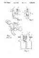
- a spinal hooksuch as hook H shown in FIG. 1
- the eyebolt Eis threaded onto the spinal rod and captured within yokes on the spinal hook.
- a nutis threaded onto the threaded post of the eyebolt to clamp the yoke between the nut and the fixation rod R.
- the eyebolt E and hook yokesprovide three degrees of fixation as represented by the arrows in FIG. 1. Details of the TSRHTM spinal implant system are disclosed in the "TSRHTM Surgical Technique Manual" provided by Danek Medical, Inc. published in 1990 which disclosure is incorporated herein by reference.
- the hooks H of the prior artare rather bulky and wide since the fixation yokes of the hook are configured to surround the spinal rod R.
- the size or bulkiness of the spinal hookis an especially important problem since a significant portion of the patient population for spinal implant systems of this type (namely the TSRHTM system) is made up of pediatric patients. Bulky implants are not easily implanted into small, thin people because the space around the vertebra is not great.
- pin holes Pare situated in each of the four posts of the double-yoke hook.
- the pin holes Pare designed so that they receive the pins of a hook holder.
- Such hook-holding instrumentsincorporate four or eight pins to correspond to the number of pinholes in the hook (which in the case of the hook H in FIG. 1 is 8 pinholes). Engagement of the pins to the pinholes is often difficult as all the components must be aligned perfectly for the instrument to be locked into place.
- the placement of the spinal hook H and engagement of the hook to the rod R by way of the eyebolt assembly Emust frequently occur in very tight quarters.
- the hookis oriented between the L2 and L3 lumbar vertebra so that the hook engages the lamina L of the L2 vertebra. It can certainly be appreciated that in smaller patients, such as pediatric patients, the room to manipulate the spinal hook to engage it to the rod is very limited.
- a new spinal hookis offered by the present invention which has a smaller profile and which includes means for more easily engaging a hook holder instrument for implanting the hook.
- the spinal hookcomprises a hook-configured shoe to which a central post top is engaged.
- the top portionincludes a pair of central posts which are displaced to form a slot therebetween.
- Each central postincludes a groove colinearly formed to receive a spinal rod within.
- the slot between the two postsis oriented with respect to the grooves so that an eyebolt assembly may be used to engage the hook to the fixation rod.
- a slotis formed in the end faces of the hook.
- the slotforms one part of a tongue and slot instrument engagement arrangement, with the hook-holding instrument including a correspondingly configured tongue.
- the tongue of the hook-holder instrumentengages within the slot on each central post of the hook to provide a more substantial engagement as the hook is being implanted.
- each of the pair of central postsinclude grooves on both lateral faces of the posts so that the spinal rod can be situated on either side of the spinal hook.
- the spinal hook of the present inventionis more readily adaptable to various spinal anatomies without requiring that the spinal rod be bent in the saggital plane in order to contact the spinal hook.
- FIG. 1shows a spinal hook engaged to a fixation rob by way of an eyebolt assembly as configured in accordance with the prior art configuration.
- FIG. 2is a side view showing the existing standard hook of FIG. 1 engaged about the lamina of the lumbar vertebra.
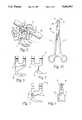
- FIG. 3is a side elevational view of a spinal hook in accordance with the present invention.
- FIG. 4is an end elevation of the spinal hook shown in FIG. 3.
- FIG. 5shows the spinal hook of FIGS. 3 and 4 engaged on a spinal rob by way of an eyebolt assembly.
- FIGS. 6-9show alternative configurations of the spinal hook of the present invention for engaging different portions of the vertebra.
- FIG. 10is a top elevational view of hook-holding instrument adapted to engage the spinal hook of the present invention.
- FIG. 1illustrates a spinal hook H of a known standard design which is used as part of a spinal fixation system, such as the TSRHTM system of Danek Medical, Inc.
- the hookis fixed to a spinal rod R by way of an eyebolt assembly E.
- the hook Halso includes a number of pinholes for engaging a conventional hook holder, such as the hook holder part number 808-036 of Danek Medical, Inc.
- the hook H depicted in FIG. 1can be a hook such as the laminar hook part number 808-007 of Danek Medical, Inc.
- FIG. 2shows the same hook H and spinal rod R engaged between the lumbar vertebra L2 and L3, specifically with the hook engaging the lamina L of the L2 vertebra.
- the spinal hook of the present invention to be described hereinis intended as a substitute for this known hook H.
- the spinal hook 10includes a shoe 11 having a bone-engaging surface 12.
- the bone-engaging surface 12can be formed in a particular shape to engage a lamina of a vertebra, for instance.
- Integral with the shoe 11 of the hook 10is a top portion 15.
- the top portion 15includes a pair of posts 17 disposed apart from each other to form a slot 19 therebetween.
- the slotis wide enough to receive an eyebolt assembly, such as eyebolt assembly E shown in FIG. 1.
- a pair of coaxial grooves 22are formed in each lateral surface 27 of both central posts 17.
- Each groove 22is configured to receive a portion of a spinal rod such as rod R shown in FIG. 1.
- the rod grooves 22are present on each lateral surface 27 of the central post 17 so that the hook 10 can be oriented on either side of a spinal rod.
- a slot 25is formed in the outwardly facing end face 28 of each of the central posts 17.
- the slots 25are preferably elongated and generally elliptical in shape and are cut into the post 17 to a sufficient depth for firm engagement by a hook-holding instrument, to be discussed herein.
- a spinal rod 29is provided which extends through a rod bore 31 of an eyebolt assembly 30.
- the eyebolt assembly 30projects through the slot 19 between the central posts 17 of the hook 10.
- the threaded post 32 of the eyebolt assemblyalso projects through the slot 19 for engagement with a nut 33.
- the nut 33is then threaded onto the post 32 until it contacts a lateral surface 27 of the two central posts 17, thereby trapping the central posts between the rod 29 and the nut 33.
- the grooves 22 on the opposite lateral surfaces of the central posts 17pinch a portion of the rod 29 to clamp the hook 10 to the rod. It should be apparent that the hook 10 could have been situated on the opposite side of the rod 29 with the rod engaged within the grooves 22 that are exposed in FIG. 5.
- a hook 40includes a shoe 41 configured for engaging the lamina of a thoracic vertebra.
- the hook 45 of FIG. 7includes a shoe 46 adapted to engage a transverse process
- hook 50 in FIG. 8is a pedicle hook having a shoe 51 adapted to engage a pedicle.
- the top portion of each of these hooksnamely top 42 of the laminar thoracic hook, top 47 of the transverse process hook, and top 52 of the pedicle hook, are configured identically to the top portion 15 described above.
- the bone-engaging surfacecan be enlarged for engaging a particular vertebral component, such as shown in FIGS. 8 and 9 for the pedicle hook 50.
- the pedicle hook 50includes a shoe 51 which is enlarged with respect to the shoes of the hook previously described.
- a transition section 53is provided between the central post top 52 and the shoe 51.
- a hook holder 60which includes a pair of pivoted arms 61. Jaws 63 at the end of the arms 61 are configured for engaging the opposite end faces of a central post hook, such as hook 10 of the present invention. Specifically, the jaws include opposite inwardly facing tongues 65 which are configured to be received within the slots 25 in the end faces 28 of the central posts 17.
- the use of the tongue and slot arrangementis an improvement over the prior pin and pinhole arrangement for the hook-engaging instrument.
- the elongated areas of contact between the tongues 65 and the slots 25provides a firmer engagement between the instrument 60 and the hook 10 that is not likely to be jarred loose or require excessive manipulation during implantation of the hook during connection to a fixation rod, such as rod 29.
- the tongue and slot configurationoffers greater lateral and angular strength and restraint than does the prior art pinhole and pin designs.
- the grooves 22 in the lateral faces of the central posts 17have a diameter of 0.188 inches. It has been found that this groove diameter is sufficient to capture a larger rod, such as a rod having a diameter of 0.250 inches.
- the slots 25 for engaging the hook-holder instrumenthave a length of 0.312 inches, a width of 0.067 inches, and a depth of 0.041 inches.
- the tongues 65 of the hook-holding instrument 60must be similarly configured but having a length, width and height slightly smaller than the corresponding dimensions of the slot 25 to allow a sliding insertion.
- the width of each central post 17is approximately 0.188 inches.
- Each of the edges of the central posts 17is rounded to avoid trauma to soft tissue surrounding the vertebra to which the hook is engaged.
- the central post hook 10 of the present inventioncan be easily configured to engage a variety of vertebral portions.
- the range of available hook designs for the central post hook 10 of the present inventionis the same as for the prior known four-post hook designs.
- the central post hook 10 of the present inventionhas the flexibility of the prior hook designs coupled with the additional flexibility of situating the hook on either side of the spinal rod depending on the requirements of the specific spinal anatomy.
- the central post configurationoffers a significantly reduced profile which reduces the risk of trauma to the patients, and which facilitates the implantation of the hooks 10, 40, 45 and 50 of the present invention.
Landscapes
- Health & Medical Sciences (AREA)
- Orthopedic Medicine & Surgery (AREA)
- Neurology (AREA)
- Life Sciences & Earth Sciences (AREA)
- Surgery (AREA)
- General Health & Medical Sciences (AREA)
- Veterinary Medicine (AREA)
- Biomedical Technology (AREA)
- Heart & Thoracic Surgery (AREA)
- Medical Informatics (AREA)
- Molecular Biology (AREA)
- Animal Behavior & Ethology (AREA)
- Nuclear Medicine, Radiotherapy & Molecular Imaging (AREA)
- Public Health (AREA)
- Engineering & Computer Science (AREA)
- Surgical Instruments (AREA)
- Prostheses (AREA)
- Orthopedics, Nursing, And Contraception (AREA)
- Pharmaceuticals Containing Other Organic And Inorganic Compounds (AREA)
- Acyclic And Carbocyclic Compounds In Medicinal Compositions (AREA)
- Hooks, Suction Cups, And Attachment By Adhesive Means (AREA)
- Stringed Musical Instruments (AREA)
- Load-Engaging Elements For Cranes (AREA)
- Sheet Holders (AREA)
- Footwear And Its Accessory, Manufacturing Method And Apparatuses (AREA)
Abstract
Description
Claims (7)
Priority Applications (17)
| Application Number | Priority Date | Filing Date | Title |
|---|---|---|---|
| US07/815,492US5246442A (en) | 1991-12-31 | 1991-12-31 | Spinal hook |
| CA002127130ACA2127130A1 (en) | 1991-12-31 | 1992-12-10 | Spinal hook |
| PCT/US1992/010658WO1993012737A1 (en) | 1991-12-31 | 1992-12-10 | Spinal hook |
| JP5511694AJP2566375B2 (en) | 1991-12-31 | 1992-12-10 | Spine hook |
| FI943112AFI943112A0 (en) | 1991-12-31 | 1992-12-10 | A spinal hook |
| DE69228319TDE69228319T2 (en) | 1991-12-31 | 1992-12-10 | BACK RACK HOOK |
| HK98104821.0AHK1005685B (en) | 1991-12-31 | 1992-12-10 | Spinal hook |
| BR9207001ABR9207001A (en) | 1991-12-31 | 1992-12-10 | Spinal hook |
| EP93901381AEP0619725B1 (en) | 1991-12-31 | 1992-12-10 | Spinal hook |
| AU32750/93AAU668535B2 (en) | 1991-12-31 | 1992-12-10 | Spinal hook |
| KR1019940700356AKR970009552B1 (en) | 1991-12-31 | 1992-12-10 | Spinal hook |
| AT93901381TATE176146T1 (en) | 1991-12-31 | 1992-12-10 | SPINAL HOOK |
| ES93901381TES2128415T3 (en) | 1991-12-31 | 1992-12-10 | SPINDLE HOOK. |
| NZ246429ANZ246429A (en) | 1991-12-31 | 1992-12-10 | Spinal fixation device, for interengaging a fixation rod with the spine, includes a groove in the lateral surface to engage the rod |
| CN92115330.9ACN1076606A (en) | 1991-12-31 | 1992-12-31 | spine hook |
| TW082100170ATW239070B (en) | 1991-12-31 | 1993-01-13 | |
| NO942453ANO942453L (en) | 1991-12-31 | 1994-06-29 | spine Hook |
Applications Claiming Priority (1)
| Application Number | Priority Date | Filing Date | Title |
|---|---|---|---|
| US07/815,492US5246442A (en) | 1991-12-31 | 1991-12-31 | Spinal hook |
Publications (1)
| Publication Number | Publication Date |
|---|---|
| US5246442Atrue US5246442A (en) | 1993-09-21 |
Family
ID=25217962
Family Applications (1)
| Application Number | Title | Priority Date | Filing Date |
|---|---|---|---|
| US07/815,492Expired - LifetimeUS5246442A (en) | 1991-12-31 | 1991-12-31 | Spinal hook |
Country Status (16)
| Country | Link |
|---|---|
| US (1) | US5246442A (en) |
| EP (1) | EP0619725B1 (en) |
| JP (1) | JP2566375B2 (en) |
| KR (1) | KR970009552B1 (en) |
| CN (1) | CN1076606A (en) |
| AT (1) | ATE176146T1 (en) |
| AU (1) | AU668535B2 (en) |
| BR (1) | BR9207001A (en) |
| CA (1) | CA2127130A1 (en) |
| DE (1) | DE69228319T2 (en) |
| ES (1) | ES2128415T3 (en) |
| FI (1) | FI943112A0 (en) |
| NO (1) | NO942453L (en) |
| NZ (1) | NZ246429A (en) |
| TW (1) | TW239070B (en) |
| WO (1) | WO1993012737A1 (en) |
Cited By (98)
| Publication number | Priority date | Publication date | Assignee | Title |
|---|---|---|---|---|
| USD346217S (en) | 1992-07-13 | 1994-04-19 | Acromed Corporation | Combined hook holder and rod mover for spinal surgery |
| US5423818A (en)* | 1993-02-17 | 1995-06-13 | Danek Medical, Inc. | Clamp for attaching a vertebral fixation element to a spinal rod |
| US5437670A (en)* | 1993-08-19 | 1995-08-01 | Danek Medical, Inc. | Attachment plate for top-tightening clamp assembly in a spinal fixation system |
| US5437669A (en)* | 1993-08-12 | 1995-08-01 | Amei Technologies Inc. | Spinal fixation systems with bifurcated connectors |
| US5527314A (en)* | 1993-01-04 | 1996-06-18 | Danek Medical, Inc. | Spinal fixation system |
| US5545167A (en)* | 1995-04-11 | 1996-08-13 | Lin; Chih-I | Retaining mechanism of vertebral fixation rod |
| WO1996028104A1 (en) | 1995-03-16 | 1996-09-19 | Alphatec Manufacturing, Inc. | Top tightening bone fixation apparatus |
| US5630816A (en)* | 1995-05-01 | 1997-05-20 | Kambin; Parviz | Double barrel spinal fixation system and method |
| US5688272A (en)* | 1995-03-30 | 1997-11-18 | Danek Medical, Inc. | Top-tightening transverse connector for a spinal fixation system |
| US5928243A (en)* | 1997-07-16 | 1999-07-27 | Spinal Concepts, Inc. | Pedicle probe and depth gage |
| US5928232A (en)* | 1994-11-16 | 1999-07-27 | Advanced Spine Fixation Systems, Incorporated | Spinal fixation system |
| US5935133A (en)* | 1997-08-26 | 1999-08-10 | Spinal Concepts, Inc. | Surgical cable system and method |
| US5944720A (en)* | 1998-03-25 | 1999-08-31 | Lipton; Glenn E | Posterior spinal fixation system |
| US5976135A (en)* | 1997-12-18 | 1999-11-02 | Sdgi Holdings, Inc. | Lateral connector assembly |
| US5989250A (en)* | 1996-10-24 | 1999-11-23 | Spinal Concepts, Inc. | Method and apparatus for spinal fixation |
| US6030389A (en)* | 1997-08-04 | 2000-02-29 | Spinal Concepts, Inc. | System and method for stabilizing the human spine with a bone plate |
| US6053921A (en)* | 1997-08-26 | 2000-04-25 | Spinal Concepts, Inc. | Surgical cable system and method |
| US6080193A (en)* | 1997-05-01 | 2000-06-27 | Spinal Concepts, Inc. | Adjustable height fusion device |
| US6132430A (en)* | 1996-10-24 | 2000-10-17 | Spinal Concepts, Inc. | Spinal fixation system |
| US6234705B1 (en) | 1999-04-06 | 2001-05-22 | Synthes (Usa) | Transconnector for coupling spinal rods |
| US6283967B1 (en) | 1999-12-17 | 2001-09-04 | Synthes (U.S.A.) | Transconnector for coupling spinal rods |
| US20020045898A1 (en)* | 2000-01-06 | 2002-04-18 | Spinal Concepts, Inc. | System and method for stabilizing the human spine with a bone plate |
| EP1201197A1 (en)* | 1999-12-10 | 2002-05-02 | Chung-Chun Yeh | Spinal fixation hook and spinal fixation device |
| US6413258B1 (en)* | 1999-08-12 | 2002-07-02 | Osteotech, Inc. | Rod-to-rod coupler |
| US6454769B2 (en) | 1997-08-04 | 2002-09-24 | Spinal Concepts, Inc. | System and method for stabilizing the human spine with a bone plate |
| US6488681B2 (en) | 2001-01-05 | 2002-12-03 | Stryker Spine S.A. | Pedicle screw assembly |
| US20030055426A1 (en)* | 2001-09-14 | 2003-03-20 | John Carbone | Biased angulation bone fixation assembly |
| US6610063B2 (en) | 2000-07-28 | 2003-08-26 | Synthes (Usa) | Spinal fixation system |
| US20040002758A1 (en)* | 2002-03-11 | 2004-01-01 | Landry Michael E. | Spinal implant including a compressible connector |
| US6770075B2 (en) | 2001-05-17 | 2004-08-03 | Robert S. Howland | Spinal fixation apparatus with enhanced axial support and methods for use |
| US20040153077A1 (en)* | 2000-11-10 | 2004-08-05 | Lutz Biedermann | Bone screw |
| US20040260285A1 (en)* | 2003-06-17 | 2004-12-23 | Eurosurgical Sa | Pedicular hooks for rachidian anchoring device |
| US20050065516A1 (en)* | 2003-09-24 | 2005-03-24 | Tae-Ahn Jahng | Method and apparatus for flexible fixation of a spine |
| US6872208B1 (en) | 2000-10-06 | 2005-03-29 | Spinal Concepts, Inc. | Adjustable transverse connector |
| US6887241B1 (en) | 2000-10-06 | 2005-05-03 | Spinal Concepts, Inc. | Adjustable transverse connector with cam activated engagers |
| US20050101953A1 (en)* | 2003-11-10 | 2005-05-12 | Simonson Peter M. | Artificial facet joint and method |
| US20050101956A1 (en)* | 2003-11-10 | 2005-05-12 | Simonson Peter M. | Artificial facet joint and method |
| US20050149020A1 (en)* | 2003-12-05 | 2005-07-07 | Tae-Ahn Jahng | Method and apparatus for flexible fixation of a spine |
| US20050154391A1 (en)* | 2003-12-30 | 2005-07-14 | Thomas Doherty | Bone anchor assemblies |
| US20050154393A1 (en)* | 2003-12-30 | 2005-07-14 | Thomas Doherty | Bone anchor assemblies and methods of manufacturing bone anchor assemblies |
| US20050187548A1 (en)* | 2004-01-13 | 2005-08-25 | Butler Michael S. | Pedicle screw constructs for spine fixation systems |
| US20050192571A1 (en)* | 2004-02-27 | 2005-09-01 | Custom Spine, Inc. | Polyaxial pedicle screw assembly |
| US20050192572A1 (en)* | 2004-02-27 | 2005-09-01 | Custom Spine, Inc. | Medialised rod pedicle screw assembly |
| US20050192573A1 (en)* | 2004-02-27 | 2005-09-01 | Custom Spine, Inc. | Biased angle polyaxial pedicle screw assembly |
| US20050203513A1 (en)* | 2003-09-24 | 2005-09-15 | Tae-Ahn Jahng | Spinal stabilization device |
| US20050228392A1 (en)* | 2004-04-12 | 2005-10-13 | Keyer Thomas R | Rod persuader |
| US20050234452A1 (en)* | 2004-04-16 | 2005-10-20 | Malandain Hugues F | Subcutaneous support |
| US20050234456A1 (en)* | 2004-04-16 | 2005-10-20 | Malandain Hugues F | Plate system for minimally invasive support of the spine |
| US20050234451A1 (en)* | 2004-04-16 | 2005-10-20 | Markworth Aaron D | Pedicle screw assembly |
| US20060009775A1 (en)* | 2004-07-06 | 2006-01-12 | Brian Dec | Spinal rod insertion instrument |
| US20060025768A1 (en)* | 2003-07-03 | 2006-02-02 | Andy Iott | Top loading spinal fixation device and instruments for loading and handling the same |
| US20060149252A1 (en)* | 2004-12-30 | 2006-07-06 | Markworth Aaron D | Bone anchorage screw with built-in hinged plate |
| US20060149237A1 (en)* | 2004-12-30 | 2006-07-06 | Markworth Aaron D | Screw with deployable interlaced dual rods |
| US20070072459A1 (en)* | 2005-09-23 | 2007-03-29 | Stahurski Consulting Inc. | Apparatus for retaining vertebrae |
| US20070093832A1 (en)* | 2004-02-27 | 2007-04-26 | Abdelgany Mahmoud F | Spring-loaded, load sharing polyaxial pedicle screw assembly and method |
| US20070161990A1 (en)* | 2005-12-21 | 2007-07-12 | Zimmer Spine, Inc. | Spinal implant hooks and systems |
| US20070270839A1 (en)* | 2006-04-05 | 2007-11-22 | Dong Myung Jeon | Multi-axial double locking bone screw assembly |
| US7314467B2 (en) | 2002-04-24 | 2008-01-01 | Medical Device Advisory Development Group, Llc. | Multi selective axis spinal fixation system |
| US20080183180A1 (en)* | 2007-01-31 | 2008-07-31 | Warsaw Orthopedic, Inc. | Implant Holder and Pusher |
| US20090005817A1 (en)* | 2007-04-30 | 2009-01-01 | Adam Friedrich | Flexible Spine Stabilization System |
| US7485132B1 (en) | 2000-10-06 | 2009-02-03 | Abbott Spine Inc. | Transverse connector with cam activated engagers |
| US20090069849A1 (en)* | 2007-09-10 | 2009-03-12 | Oh Younghoon | Dynamic screw system |
| US20090248076A1 (en)* | 2008-03-26 | 2009-10-01 | Reynolds Martin A | Interspinous Process Spacer Having Tight Access Offset Hooks |
| US20090248079A1 (en)* | 2008-03-26 | 2009-10-01 | Kwak Seungkyu Daniel | S-Shaped Interspinous Process Spacer Having Tight Access Offset Hooks |
| US20090248090A1 (en)* | 2007-12-28 | 2009-10-01 | Pronto Products, Llc | Rib bone tissue clamp |
| US7678114B2 (en) | 2005-12-20 | 2010-03-16 | Warsaw Orthopedic, Inc. | Vertebral implant inserter and method of use |
| US7708764B2 (en) | 2003-11-10 | 2010-05-04 | Simonson Peter M | Method for creating an artificial facet |
| US7766947B2 (en) | 2001-10-31 | 2010-08-03 | Ortho Development Corporation | Cervical plate for stabilizing the human spine |
| US7815665B2 (en) | 2003-09-24 | 2010-10-19 | N Spine, Inc. | Adjustable spinal stabilization system |
| US8388660B1 (en) | 2006-08-01 | 2013-03-05 | Samy Abdou | Devices and methods for superior fixation of orthopedic devices onto the vertebral column |
| US8480715B2 (en) | 2007-05-22 | 2013-07-09 | Zimmer Spine, Inc. | Spinal implant system and method |
| US20130231704A1 (en)* | 2010-11-10 | 2013-09-05 | Zimmer Spine | Bone anchor |
| US8623057B2 (en) | 2003-09-24 | 2014-01-07 | DePuy Synthes Products, LLC | Spinal stabilization device |
| US8911476B2 (en) | 2009-06-23 | 2014-12-16 | Osteomed, Llc | Bone plates, screws, and instruments |
| US8940019B2 (en) | 2007-12-28 | 2015-01-27 | Osteomed Spine, Inc. | Bone tissue fixation device and method |
| US8961564B2 (en) | 2008-12-23 | 2015-02-24 | Osteomed Llc | Bone tissue clamp |
| US8992576B2 (en) | 2008-12-17 | 2015-03-31 | DePuy Synthes Products, LLC | Posterior spine dynamic stabilizer |
| US9179940B2 (en) | 2005-12-06 | 2015-11-10 | Globus Medical, Inc. | System and method for replacement of spinal motion segment |
| US9211147B2 (en) | 2009-06-23 | 2015-12-15 | Osteomed Llc | Spinous process fusion implants |
| US20170065306A1 (en)* | 2004-02-17 | 2017-03-09 | Globus Medical, Inc. | Facet joint replacement instruments and methods |
| US10499954B2 (en) | 2016-03-10 | 2019-12-10 | Nuvasive, Inc. | Bone anchor with deployable purchase element |
| US10543107B2 (en) | 2009-12-07 | 2020-01-28 | Samy Abdou | Devices and methods for minimally invasive spinal stabilization and instrumentation |
| US10548740B1 (en) | 2016-10-25 | 2020-02-04 | Samy Abdou | Devices and methods for vertebral bone realignment |
| US10575961B1 (en) | 2011-09-23 | 2020-03-03 | Samy Abdou | Spinal fixation devices and methods of use |
| US10575876B2 (en) | 2016-04-20 | 2020-03-03 | K2M, Inc. | Spinal stabilization assemblies with bone hooks |
| US10695105B2 (en) | 2012-08-28 | 2020-06-30 | Samy Abdou | Spinal fixation devices and methods of use |
| US20200237411A1 (en)* | 2019-01-30 | 2020-07-30 | Medos International Sarl | Surgical device for spinal fixation |
| USD896384S1 (en) | 2019-06-07 | 2020-09-15 | GetSet Surgical SA | Spinal fusion cage |
| US10857003B1 (en) | 2015-10-14 | 2020-12-08 | Samy Abdou | Devices and methods for vertebral stabilization |
| US10918498B2 (en) | 2004-11-24 | 2021-02-16 | Samy Abdou | Devices and methods for inter-vertebral orthopedic device placement |
| US10973648B1 (en) | 2016-10-25 | 2021-04-13 | Samy Abdou | Devices and methods for vertebral bone realignment |
| US11006982B2 (en) | 2012-02-22 | 2021-05-18 | Samy Abdou | Spinous process fixation devices and methods of use |
| USD926312S1 (en) | 2019-06-07 | 2021-07-27 | GetSet Surgical SA | Surgical instrument handle |
| USD926978S1 (en) | 2019-06-07 | 2021-08-03 | GetSet Surgical SA | Surgical instrument handle |
| USD927687S1 (en) | 2019-06-07 | 2021-08-10 | GetSet Surgical SA | Surgical instrument handle |
| US11173040B2 (en) | 2012-10-22 | 2021-11-16 | Cogent Spine, LLC | Devices and methods for spinal stabilization and instrumentation |
| US11179248B2 (en) | 2018-10-02 | 2021-11-23 | Samy Abdou | Devices and methods for spinal implantation |
| US11311314B2 (en) | 2018-07-31 | 2022-04-26 | GetSet Surgical SA | Spinal surgery systems and methods |
Families Citing this family (3)
| Publication number | Priority date | Publication date | Assignee | Title |
|---|---|---|---|---|
| CN100420425C (en)* | 2002-12-24 | 2008-09-24 | 叶中权 | Vertebra fixing reductor |
| US7811310B2 (en)* | 2005-05-04 | 2010-10-12 | Spinefrontier, Inc | Multistage spinal fixation locking mechanism |
| KR101715387B1 (en)* | 2016-03-25 | 2017-03-22 | 충남대학교 산학협력단 | Portable electrospinning device |
Citations (5)
| Publication number | Priority date | Publication date | Assignee | Title |
|---|---|---|---|---|
| US4567884A (en)* | 1982-12-01 | 1986-02-04 | Edwards Charles C | Spinal hook |
| US4648388A (en)* | 1985-11-01 | 1987-03-10 | Acromed Corporation | Apparatus and method for maintaining vertebrae in a desired relationship |
| US4815453A (en)* | 1983-05-04 | 1989-03-28 | Societe De Fabrication De Materiel Orthopedique (Sofamor) | Device for supporting the rachis |
| US5002542A (en)* | 1989-10-30 | 1991-03-26 | Synthes U.S.A. | Pedicle screw clamp |
| US5007909A (en)* | 1986-11-05 | 1991-04-16 | Chaim Rogozinski | Apparatus for internally fixing the spine |
- 1991
- 1991-12-31USUS07/815,492patent/US5246442A/ennot_activeExpired - Lifetime
- 1992
- 1992-12-10FIFI943112Apatent/FI943112A0/ennot_activeApplication Discontinuation
- 1992-12-10ESES93901381Tpatent/ES2128415T3/ennot_activeExpired - Lifetime
- 1992-12-10WOPCT/US1992/010658patent/WO1993012737A1/enactiveIP Right Grant
- 1992-12-10ATAT93901381Tpatent/ATE176146T1/ennot_activeIP Right Cessation
- 1992-12-10CACA002127130Apatent/CA2127130A1/ennot_activeAbandoned
- 1992-12-10EPEP93901381Apatent/EP0619725B1/ennot_activeExpired - Lifetime
- 1992-12-10BRBR9207001Apatent/BR9207001A/enactiveSearch and Examination
- 1992-12-10KRKR1019940700356Apatent/KR970009552B1/ennot_activeExpired - Fee Related
- 1992-12-10AUAU32750/93Apatent/AU668535B2/ennot_activeCeased
- 1992-12-10DEDE69228319Tpatent/DE69228319T2/ennot_activeExpired - Fee Related
- 1992-12-10NZNZ246429Apatent/NZ246429A/enunknown
- 1992-12-10JPJP5511694Apatent/JP2566375B2/ennot_activeExpired - Fee Related
- 1992-12-31CNCN92115330.9Apatent/CN1076606A/enactivePending
- 1993
- 1993-01-13TWTW082100170Apatent/TW239070B/zhactive
- 1994
- 1994-06-29NONO942453Apatent/NO942453L/enunknown
Patent Citations (6)
| Publication number | Priority date | Publication date | Assignee | Title |
|---|---|---|---|---|
| US4567884A (en)* | 1982-12-01 | 1986-02-04 | Edwards Charles C | Spinal hook |
| US4815453A (en)* | 1983-05-04 | 1989-03-28 | Societe De Fabrication De Materiel Orthopedique (Sofamor) | Device for supporting the rachis |
| US4648388A (en)* | 1985-11-01 | 1987-03-10 | Acromed Corporation | Apparatus and method for maintaining vertebrae in a desired relationship |
| US4648388B1 (en)* | 1985-11-01 | 1995-10-31 | Acromed Corp | Apparatus and method for maintaining vertebrae in a desired relationship |
| US5007909A (en)* | 1986-11-05 | 1991-04-16 | Chaim Rogozinski | Apparatus for internally fixing the spine |
| US5002542A (en)* | 1989-10-30 | 1991-03-26 | Synthes U.S.A. | Pedicle screw clamp |
Non-Patent Citations (1)
| Title |
|---|
| TSRH Surgical Technique Manual of Danek Medical, Inc. (1990).* |
Cited By (210)
| Publication number | Priority date | Publication date | Assignee | Title |
|---|---|---|---|---|
| USD346217S (en) | 1992-07-13 | 1994-04-19 | Acromed Corporation | Combined hook holder and rod mover for spinal surgery |
| US5527314A (en)* | 1993-01-04 | 1996-06-18 | Danek Medical, Inc. | Spinal fixation system |
| US5423818A (en)* | 1993-02-17 | 1995-06-13 | Danek Medical, Inc. | Clamp for attaching a vertebral fixation element to a spinal rod |
| US5437669A (en)* | 1993-08-12 | 1995-08-01 | Amei Technologies Inc. | Spinal fixation systems with bifurcated connectors |
| US5437670A (en)* | 1993-08-19 | 1995-08-01 | Danek Medical, Inc. | Attachment plate for top-tightening clamp assembly in a spinal fixation system |
| US5624441A (en)* | 1993-08-19 | 1997-04-29 | Danek Medical, Inc. | Attachment plate for top-tightening clamp assembly in a spinal fixation system |
| WO1995017863A1 (en)* | 1993-12-30 | 1995-07-06 | Danek Medical, Inc. | Clamp for attaching a vertebral fixation element to a spinal rod |
| US5928232A (en)* | 1994-11-16 | 1999-07-27 | Advanced Spine Fixation Systems, Incorporated | Spinal fixation system |
| WO1996028104A1 (en) | 1995-03-16 | 1996-09-19 | Alphatec Manufacturing, Inc. | Top tightening bone fixation apparatus |
| US5562661A (en)* | 1995-03-16 | 1996-10-08 | Alphatec Manufacturing Incorporated | Top tightening bone fixation apparatus |
| US5980521A (en)* | 1995-03-30 | 1999-11-09 | Sdgi Holdings,Inc. | Top-tightening transverse connector for a spinal fixation system |
| US5688272A (en)* | 1995-03-30 | 1997-11-18 | Danek Medical, Inc. | Top-tightening transverse connector for a spinal fixation system |
| US5545167A (en)* | 1995-04-11 | 1996-08-13 | Lin; Chih-I | Retaining mechanism of vertebral fixation rod |
| US5630816A (en)* | 1995-05-01 | 1997-05-20 | Kambin; Parviz | Double barrel spinal fixation system and method |
| US6613050B1 (en) | 1996-10-24 | 2003-09-02 | Spinal Concepts, Inc. | Method and apparatus for spinal fixation |
| US6595992B1 (en) | 1996-10-24 | 2003-07-22 | Spinal Concepts, Inc. | Method and apparatus for spinal fixation |
| US6416515B1 (en) | 1996-10-24 | 2002-07-09 | Spinal Concepts, Inc. | Spinal fixation system |
| US5989250A (en)* | 1996-10-24 | 1999-11-23 | Spinal Concepts, Inc. | Method and apparatus for spinal fixation |
| US6562040B1 (en) | 1996-10-24 | 2003-05-13 | Spinal Concepts, Inc. | Spinal fixation system |
| US6132430A (en)* | 1996-10-24 | 2000-10-17 | Spinal Concepts, Inc. | Spinal fixation system |
| US6576016B1 (en) | 1997-05-01 | 2003-06-10 | Spinal Concepts, Inc. | Adjustable height fusion device |
| US6080193A (en)* | 1997-05-01 | 2000-06-27 | Spinal Concepts, Inc. | Adjustable height fusion device |
| US5928243A (en)* | 1997-07-16 | 1999-07-27 | Spinal Concepts, Inc. | Pedicle probe and depth gage |
| US6030389A (en)* | 1997-08-04 | 2000-02-29 | Spinal Concepts, Inc. | System and method for stabilizing the human spine with a bone plate |
| US6454769B2 (en) | 1997-08-04 | 2002-09-24 | Spinal Concepts, Inc. | System and method for stabilizing the human spine with a bone plate |
| US5964769A (en)* | 1997-08-26 | 1999-10-12 | Spinal Concepts, Inc. | Surgical cable system and method |
| US5935133A (en)* | 1997-08-26 | 1999-08-10 | Spinal Concepts, Inc. | Surgical cable system and method |
| US6682533B1 (en) | 1997-08-26 | 2004-01-27 | Spinal Concepts, Inc. | Surgical cable system and method |
| US6053921A (en)* | 1997-08-26 | 2000-04-25 | Spinal Concepts, Inc. | Surgical cable system and method |
| US5976135A (en)* | 1997-12-18 | 1999-11-02 | Sdgi Holdings, Inc. | Lateral connector assembly |
| US5944720A (en)* | 1998-03-25 | 1999-08-31 | Lipton; Glenn E | Posterior spinal fixation system |
| US6306137B2 (en) | 1999-04-06 | 2001-10-23 | Synthes (U.S.A.) | Transconnector for coupling spinal rods |
| US6234705B1 (en) | 1999-04-06 | 2001-05-22 | Synthes (Usa) | Transconnector for coupling spinal rods |
| US6413258B1 (en)* | 1999-08-12 | 2002-07-02 | Osteotech, Inc. | Rod-to-rod coupler |
| EP1201197A1 (en)* | 1999-12-10 | 2002-05-02 | Chung-Chun Yeh | Spinal fixation hook and spinal fixation device |
| US6283967B1 (en) | 1999-12-17 | 2001-09-04 | Synthes (U.S.A.) | Transconnector for coupling spinal rods |
| US6736817B2 (en) | 1999-12-17 | 2004-05-18 | Thomas N. Troxell | Transconnector for coupling spinal rods |
| US6964664B2 (en) | 2000-01-06 | 2005-11-15 | Spinal Concepts Inc. | System and method for stabilizing the human spine with a bone plate |
| US8025677B2 (en) | 2000-01-06 | 2011-09-27 | Zimmer Spine, Inc. | System and method for stabilizing the human spine with a bone plate |
| US20020045898A1 (en)* | 2000-01-06 | 2002-04-18 | Spinal Concepts, Inc. | System and method for stabilizing the human spine with a bone plate |
| US20070055243A1 (en)* | 2000-07-28 | 2007-03-08 | Synthes (Usa) | Spinal fixation system |
| US6610063B2 (en) | 2000-07-28 | 2003-08-26 | Synthes (Usa) | Spinal fixation system |
| US20040039386A1 (en)* | 2000-07-28 | 2004-02-26 | Synthes (Usa) | Spinal fixation system |
| US20100042166A1 (en)* | 2000-07-28 | 2010-02-18 | Kumar Kris G | Spinal fixation system |
| US7118571B2 (en) | 2000-07-28 | 2006-10-10 | Synthes (U.S.A.) | Spinal fixation system |
| US9504499B2 (en) | 2000-07-28 | 2016-11-29 | DePuy Synthes Products, Inc. | Spinal fixation system |
| US8551146B2 (en) | 2000-07-28 | 2013-10-08 | DePuy Synthes Products, LLC | Spinal fixation system |
| US8221470B2 (en) | 2000-07-28 | 2012-07-17 | Synthes Usa, Llc | Spinal fixation system |
| US20090138047A1 (en)* | 2000-10-06 | 2009-05-28 | Abbott Spine, Inc. | Transverse connector with cam activated engagers |
| US6872208B1 (en) | 2000-10-06 | 2005-03-29 | Spinal Concepts, Inc. | Adjustable transverse connector |
| US6887241B1 (en) | 2000-10-06 | 2005-05-03 | Spinal Concepts, Inc. | Adjustable transverse connector with cam activated engagers |
| US7485132B1 (en) | 2000-10-06 | 2009-02-03 | Abbott Spine Inc. | Transverse connector with cam activated engagers |
| US8062338B2 (en) | 2000-10-06 | 2011-11-22 | Zimmer Spine, Inc. | Transverse connector with cam activated engagers |
| US20110125195A1 (en)* | 2000-10-11 | 2011-05-26 | Lutz Biedermann | Bone Screw |
| US9498256B2 (en) | 2000-11-10 | 2016-11-22 | Biedermann Technologies Gmbh & Co. Kg | Bone screw |
| US8409260B2 (en) | 2000-11-10 | 2013-04-02 | Biedermann Technologies Gmbh & Co. Kg | Bone screw |
| US20060084995A1 (en)* | 2000-11-10 | 2006-04-20 | Biedermann Motech Gmbh | Bone screw |
| US9566093B2 (en) | 2000-11-10 | 2017-02-14 | Biedermann Technologies Gmbh & Co. Kg | Bone screw |
| US11197694B2 (en) | 2000-11-10 | 2021-12-14 | Biedermann Technologies Gmbh & Co. Kg | Bone screw |
| US10058353B2 (en) | 2000-11-10 | 2018-08-28 | Biedermann Technologies Gmbh & Co. Kg | Bone screw |
| US20110066189A2 (en)* | 2000-11-10 | 2011-03-17 | Biedermann Motech Gmbh | Bone screw |
| US20040153077A1 (en)* | 2000-11-10 | 2004-08-05 | Lutz Biedermann | Bone screw |
| US8945194B2 (en) | 2000-11-10 | 2015-02-03 | Biedermann Technologies Gmbh & Co. Kg | Bone screw |
| US20060106383A1 (en)* | 2000-11-10 | 2006-05-18 | Biedermann Motech Gmbh | Bone screw |
| US7785354B2 (en) | 2000-11-10 | 2010-08-31 | Biedermann Motech Gmbh | Bone screw |
| US8864803B2 (en) | 2000-11-10 | 2014-10-21 | Biedermann Technologies Gmbh & Co. Kg | Bone screw |
| US6858030B2 (en) | 2001-01-05 | 2005-02-22 | Stryker Spine | Pedicle screw assembly and methods therefor |
| US8894692B2 (en) | 2001-01-05 | 2014-11-25 | Stryker France | Pedicle screw assembly and methods therefor |
| US6488681B2 (en) | 2001-01-05 | 2002-12-03 | Stryker Spine S.A. | Pedicle screw assembly |
| USRE42932E1 (en)* | 2001-01-05 | 2011-11-15 | Stryker France | Pedicle screw assembly and methods therefor |
| US6770075B2 (en) | 2001-05-17 | 2004-08-03 | Robert S. Howland | Spinal fixation apparatus with enhanced axial support and methods for use |
| US20040243126A1 (en)* | 2001-09-14 | 2004-12-02 | Stryker Spine | Methods for stabilizing bone using spinal fixation devices |
| US9662144B2 (en) | 2001-09-14 | 2017-05-30 | Stryker European Holdings I, Llc | Stabilizing bone using spinal fixation devices and systems |
| US6974460B2 (en) | 2001-09-14 | 2005-12-13 | Stryker Spine | Biased angulation bone fixation assembly |
| US8506600B2 (en) | 2001-09-14 | 2013-08-13 | Stryker Spine | Methods for stabilizing bone using spinal fixation devices |
| US8870930B2 (en) | 2001-09-14 | 2014-10-28 | Stryker Spine | Methods for stabilizing bone using spinal fixation devices |
| US20030055426A1 (en)* | 2001-09-14 | 2003-03-20 | John Carbone | Biased angulation bone fixation assembly |
| US10517646B2 (en) | 2001-09-14 | 2019-12-31 | Stryker European Holdings I, Llc | Stabilizing bone using spinal fixation devices and systems |
| US7766947B2 (en) | 2001-10-31 | 2010-08-03 | Ortho Development Corporation | Cervical plate for stabilizing the human spine |
| US7637952B2 (en) | 2002-03-11 | 2009-12-29 | Zimmer Spine, Inc. | Instrumentation and procedure for implanting spinal implant devices |
| US20040002758A1 (en)* | 2002-03-11 | 2004-01-01 | Landry Michael E. | Spinal implant including a compressible connector |
| US20040030387A1 (en)* | 2002-03-11 | 2004-02-12 | Landry Michael E. | Instrumentation and procedure for implanting spinal implant devices |
| US7314467B2 (en) | 2002-04-24 | 2008-01-01 | Medical Device Advisory Development Group, Llc. | Multi selective axis spinal fixation system |
| US20040260285A1 (en)* | 2003-06-17 | 2004-12-23 | Eurosurgical Sa | Pedicular hooks for rachidian anchoring device |
| US20060025768A1 (en)* | 2003-07-03 | 2006-02-02 | Andy Iott | Top loading spinal fixation device and instruments for loading and handling the same |
| US8979900B2 (en) | 2003-09-24 | 2015-03-17 | DePuy Synthes Products, LLC | Spinal stabilization device |
| US7993370B2 (en) | 2003-09-24 | 2011-08-09 | N Spine, Inc. | Method and apparatus for flexible fixation of a spine |
| US20050065516A1 (en)* | 2003-09-24 | 2005-03-24 | Tae-Ahn Jahng | Method and apparatus for flexible fixation of a spine |
| US7326210B2 (en) | 2003-09-24 | 2008-02-05 | N Spine, Inc | Spinal stabilization device |
| US7815665B2 (en) | 2003-09-24 | 2010-10-19 | N Spine, Inc. | Adjustable spinal stabilization system |
| US8968366B2 (en) | 2003-09-24 | 2015-03-03 | DePuy Synthes Products, LLC | Method and apparatus for flexible fixation of a spine |
| WO2006063107A3 (en)* | 2003-09-24 | 2006-12-28 | N Spine Inc | Spinal stabilization device |
| US20050203513A1 (en)* | 2003-09-24 | 2005-09-15 | Tae-Ahn Jahng | Spinal stabilization device |
| US20050203517A1 (en)* | 2003-09-24 | 2005-09-15 | N Spine, Inc. | Spinal stabilization device |
| US8623057B2 (en) | 2003-09-24 | 2014-01-07 | DePuy Synthes Products, LLC | Spinal stabilization device |
| US20050101953A1 (en)* | 2003-11-10 | 2005-05-12 | Simonson Peter M. | Artificial facet joint and method |
| US20090216279A1 (en)* | 2003-11-10 | 2009-08-27 | Simonson Peter M | Artificial facet joint and method |
| US20050101956A1 (en)* | 2003-11-10 | 2005-05-12 | Simonson Peter M. | Artificial facet joint and method |
| US7083622B2 (en) | 2003-11-10 | 2006-08-01 | Simonson Peter M | Artificial facet joint and method |
| US8142478B2 (en) | 2003-11-10 | 2012-03-27 | Simonson Peter M | Artificial facet joint and method |
| US7708764B2 (en) | 2003-11-10 | 2010-05-04 | Simonson Peter M | Method for creating an artificial facet |
| US20080262545A1 (en)* | 2003-11-10 | 2008-10-23 | Simonson Peter M | Artificial Facet Joint and Method |
| US20050149020A1 (en)* | 2003-12-05 | 2005-07-07 | Tae-Ahn Jahng | Method and apparatus for flexible fixation of a spine |
| US7763052B2 (en) | 2003-12-05 | 2010-07-27 | N Spine, Inc. | Method and apparatus for flexible fixation of a spine |
| US20050154391A1 (en)* | 2003-12-30 | 2005-07-14 | Thomas Doherty | Bone anchor assemblies |
| US20050154393A1 (en)* | 2003-12-30 | 2005-07-14 | Thomas Doherty | Bone anchor assemblies and methods of manufacturing bone anchor assemblies |
| US20050159750A1 (en)* | 2003-12-30 | 2005-07-21 | Thomas Doherty | Bone anchor assemblies and methods of manufacturing bone anchor assemblies |
| US20050203515A1 (en)* | 2003-12-30 | 2005-09-15 | Thomas Doherty | Bone anchor assemblies |
| US7678137B2 (en) | 2004-01-13 | 2010-03-16 | Life Spine, Inc. | Pedicle screw constructs for spine fixation systems |
| US8092494B2 (en) | 2004-01-13 | 2012-01-10 | Life Spine, Inc. | Pedicle screw constructs for spine fixation systems |
| US20050187548A1 (en)* | 2004-01-13 | 2005-08-25 | Butler Michael S. | Pedicle screw constructs for spine fixation systems |
| US20170065306A1 (en)* | 2004-02-17 | 2017-03-09 | Globus Medical, Inc. | Facet joint replacement instruments and methods |
| US7763057B2 (en) | 2004-02-27 | 2010-07-27 | Custom Spine, Inc. | Biased angle polyaxial pedicle screw assembly |
| US8439954B2 (en) | 2004-02-27 | 2013-05-14 | Custom Spine, Inc. | Spring-loaded, load sharing polyaxial pedicle screw assembly and method |
| US8652178B2 (en) | 2004-02-27 | 2014-02-18 | Custom Spine, Inc. | Polyaxial pedicle screw assembly and method |
| US20050192573A1 (en)* | 2004-02-27 | 2005-09-01 | Custom Spine, Inc. | Biased angle polyaxial pedicle screw assembly |
| US20050192572A1 (en)* | 2004-02-27 | 2005-09-01 | Custom Spine, Inc. | Medialised rod pedicle screw assembly |
| US7819902B2 (en) | 2004-02-27 | 2010-10-26 | Custom Spine, Inc. | Medialised rod pedicle screw assembly |
| US7862594B2 (en) | 2004-02-27 | 2011-01-04 | Custom Spine, Inc. | Polyaxial pedicle screw assembly |
| US20110034258A1 (en)* | 2004-02-27 | 2011-02-10 | Custom Spine, Inc | Polyaxial Pedicle Screw Assembly and Method |
| US7892257B2 (en) | 2004-02-27 | 2011-02-22 | Custom Spine, Inc. | Spring loaded, load sharing polyaxial pedicle screw assembly and method |
| US20050192571A1 (en)* | 2004-02-27 | 2005-09-01 | Custom Spine, Inc. | Polyaxial pedicle screw assembly |
| US20110054546A1 (en)* | 2004-02-27 | 2011-03-03 | Custom Spine, Inc | Polyaxial Pedicle Screw Assembly |
| US7163539B2 (en) | 2004-02-27 | 2007-01-16 | Custom Spine, Inc. | Biased angle polyaxial pedicle screw assembly |
| US20070093832A1 (en)* | 2004-02-27 | 2007-04-26 | Abdelgany Mahmoud F | Spring-loaded, load sharing polyaxial pedicle screw assembly and method |
| US20070093831A1 (en)* | 2004-02-27 | 2007-04-26 | Abdelgany Mahmoud F | Biased angle polyaxial pedicle screw assembly |
| US20050228392A1 (en)* | 2004-04-12 | 2005-10-13 | Keyer Thomas R | Rod persuader |
| US7491207B2 (en) | 2004-04-12 | 2009-02-17 | Synthes Usa, Llc | Rod persuader |
| US20050234456A1 (en)* | 2004-04-16 | 2005-10-20 | Malandain Hugues F | Plate system for minimally invasive support of the spine |
| US7648520B2 (en) | 2004-04-16 | 2010-01-19 | Kyphon Sarl | Pedicle screw assembly |
| US20050234452A1 (en)* | 2004-04-16 | 2005-10-20 | Malandain Hugues F | Subcutaneous support |
| US7618418B2 (en) | 2004-04-16 | 2009-11-17 | Kyphon Sarl | Plate system for minimally invasive support of the spine |
| US7524323B2 (en) | 2004-04-16 | 2009-04-28 | Kyphon Sarl | Subcutaneous support |
| US20100076494A1 (en)* | 2004-04-16 | 2010-03-25 | Kyphon Sarl | Pedicle screw assembly |
| US20050234451A1 (en)* | 2004-04-16 | 2005-10-20 | Markworth Aaron D | Pedicle screw assembly |
| US20060009775A1 (en)* | 2004-07-06 | 2006-01-12 | Brian Dec | Spinal rod insertion instrument |
| US7371239B2 (en) | 2004-07-06 | 2008-05-13 | Synthes (U.S.A.) | Spinal rod insertion instrument |
| US10918498B2 (en) | 2004-11-24 | 2021-02-16 | Samy Abdou | Devices and methods for inter-vertebral orthopedic device placement |
| US11096799B2 (en) | 2004-11-24 | 2021-08-24 | Samy Abdou | Devices and methods for inter-vertebral orthopedic device placement |
| US11992423B2 (en) | 2004-11-24 | 2024-05-28 | Samy Abdou | Devices and methods for inter-vertebral orthopedic device placement |
| US20060149237A1 (en)* | 2004-12-30 | 2006-07-06 | Markworth Aaron D | Screw with deployable interlaced dual rods |
| US7811311B2 (en) | 2004-12-30 | 2010-10-12 | Warsaw Orthopedic, Inc. | Screw with deployable interlaced dual rods |
| US20060149252A1 (en)* | 2004-12-30 | 2006-07-06 | Markworth Aaron D | Bone anchorage screw with built-in hinged plate |
| US7789899B2 (en) | 2004-12-30 | 2010-09-07 | Warsaw Orthopedic, Inc. | Bone anchorage screw with built-in hinged plate |
| US8075597B2 (en)* | 2005-09-23 | 2011-12-13 | Applied Orthopaedics Llc | Apparatus for retaining vertebrae |
| US20070072459A1 (en)* | 2005-09-23 | 2007-03-29 | Stahurski Consulting Inc. | Apparatus for retaining vertebrae |
| US9179940B2 (en) | 2005-12-06 | 2015-11-10 | Globus Medical, Inc. | System and method for replacement of spinal motion segment |
| US7678114B2 (en) | 2005-12-20 | 2010-03-16 | Warsaw Orthopedic, Inc. | Vertebral implant inserter and method of use |
| US20070161990A1 (en)* | 2005-12-21 | 2007-07-12 | Zimmer Spine, Inc. | Spinal implant hooks and systems |
| US7896902B2 (en) | 2006-04-05 | 2011-03-01 | Dong Myung Jeon | Multi-axial double locking bone screw assembly |
| US20070270839A1 (en)* | 2006-04-05 | 2007-11-22 | Dong Myung Jeon | Multi-axial double locking bone screw assembly |
| US8388660B1 (en) | 2006-08-01 | 2013-03-05 | Samy Abdou | Devices and methods for superior fixation of orthopedic devices onto the vertebral column |
| US20080183180A1 (en)* | 2007-01-31 | 2008-07-31 | Warsaw Orthopedic, Inc. | Implant Holder and Pusher |
| US20090005817A1 (en)* | 2007-04-30 | 2009-01-01 | Adam Friedrich | Flexible Spine Stabilization System |
| US9220538B2 (en) | 2007-04-30 | 2015-12-29 | Globus Medical, Inc. | Flexible element for spine stabilization system |
| US8465526B2 (en) | 2007-04-30 | 2013-06-18 | Globus Medical, Inc. | Flexible spine stabilization system |
| US9339297B2 (en) | 2007-04-30 | 2016-05-17 | Globus Medical, Inc. | Flexible spine stabilization system |
| US9211142B2 (en) | 2007-04-30 | 2015-12-15 | Globus Medical, Inc. | Flexible element for spine stabilization system |
| US8480715B2 (en) | 2007-05-22 | 2013-07-09 | Zimmer Spine, Inc. | Spinal implant system and method |
| US20090069849A1 (en)* | 2007-09-10 | 2009-03-12 | Oh Younghoon | Dynamic screw system |
| US20090248090A1 (en)* | 2007-12-28 | 2009-10-01 | Pronto Products, Llc | Rib bone tissue clamp |
| US8940019B2 (en) | 2007-12-28 | 2015-01-27 | Osteomed Spine, Inc. | Bone tissue fixation device and method |
| US20090248079A1 (en)* | 2008-03-26 | 2009-10-01 | Kwak Seungkyu Daniel | S-Shaped Interspinous Process Spacer Having Tight Access Offset Hooks |
| US8313512B2 (en) | 2008-03-26 | 2012-11-20 | Depuy Spine, Inc. | S-shaped interspinous process spacer having tight access offset hooks |
| US8025678B2 (en) | 2008-03-26 | 2011-09-27 | Depuy Spine, Inc. | Interspinous process spacer having tight access offset hooks |
| US20090248076A1 (en)* | 2008-03-26 | 2009-10-01 | Reynolds Martin A | Interspinous Process Spacer Having Tight Access Offset Hooks |
| US8992576B2 (en) | 2008-12-17 | 2015-03-31 | DePuy Synthes Products, LLC | Posterior spine dynamic stabilizer |
| US8961564B2 (en) | 2008-12-23 | 2015-02-24 | Osteomed Llc | Bone tissue clamp |
| US10010356B2 (en) | 2009-06-23 | 2018-07-03 | Wenzel Spine, Inc. | Bone plates, screws and instruments |
| US8911476B2 (en) | 2009-06-23 | 2014-12-16 | Osteomed, Llc | Bone plates, screws, and instruments |
| US9211147B2 (en) | 2009-06-23 | 2015-12-15 | Osteomed Llc | Spinous process fusion implants |
| US9456858B2 (en) | 2009-06-23 | 2016-10-04 | Osteomed, Llc | Bone plates, screws and instruments |
| US10857004B2 (en) | 2009-12-07 | 2020-12-08 | Samy Abdou | Devices and methods for minimally invasive spinal stabilization and instrumentation |
| US10543107B2 (en) | 2009-12-07 | 2020-01-28 | Samy Abdou | Devices and methods for minimally invasive spinal stabilization and instrumentation |
| US10610380B2 (en) | 2009-12-07 | 2020-04-07 | Samy Abdou | Devices and methods for minimally invasive spinal stabilization and instrumentation |
| US10945861B2 (en) | 2009-12-07 | 2021-03-16 | Samy Abdou | Devices and methods for minimally invasive spinal stabilization and instrumentation |
| US11918486B2 (en) | 2009-12-07 | 2024-03-05 | Samy Abdou | Devices and methods for minimally invasive spinal stabilization and instrumentation |
| US20130231704A1 (en)* | 2010-11-10 | 2013-09-05 | Zimmer Spine | Bone anchor |
| US9113961B2 (en)* | 2010-11-10 | 2015-08-25 | Zimmer Spine | Bone anchor |
| US12167973B2 (en) | 2011-09-23 | 2024-12-17 | Samy Abdou | Spinal fixation devices and methods of use |
| US11517449B2 (en) | 2011-09-23 | 2022-12-06 | Samy Abdou | Spinal fixation devices and methods of use |
| US11324608B2 (en) | 2011-09-23 | 2022-05-10 | Samy Abdou | Spinal fixation devices and methods of use |
| US10575961B1 (en) | 2011-09-23 | 2020-03-03 | Samy Abdou | Spinal fixation devices and methods of use |
| US11839413B2 (en) | 2012-02-22 | 2023-12-12 | Samy Abdou | Spinous process fixation devices and methods of use |
| US11006982B2 (en) | 2012-02-22 | 2021-05-18 | Samy Abdou | Spinous process fixation devices and methods of use |
| US11559336B2 (en) | 2012-08-28 | 2023-01-24 | Samy Abdou | Spinal fixation devices and methods of use |
| US10695105B2 (en) | 2012-08-28 | 2020-06-30 | Samy Abdou | Spinal fixation devices and methods of use |
| US11918483B2 (en) | 2012-10-22 | 2024-03-05 | Cogent Spine Llc | Devices and methods for spinal stabilization and instrumentation |
| US11173040B2 (en) | 2012-10-22 | 2021-11-16 | Cogent Spine, LLC | Devices and methods for spinal stabilization and instrumentation |
| US11246718B2 (en) | 2015-10-14 | 2022-02-15 | Samy Abdou | Devices and methods for vertebral stabilization |
| US10857003B1 (en) | 2015-10-14 | 2020-12-08 | Samy Abdou | Devices and methods for vertebral stabilization |
| US11596447B2 (en) | 2016-03-10 | 2023-03-07 | Nuvasive, Inc. | Bone anchor with deployable purchase element |
| US10499954B2 (en) | 2016-03-10 | 2019-12-10 | Nuvasive, Inc. | Bone anchor with deployable purchase element |
| US10575876B2 (en) | 2016-04-20 | 2020-03-03 | K2M, Inc. | Spinal stabilization assemblies with bone hooks |
| US10548740B1 (en) | 2016-10-25 | 2020-02-04 | Samy Abdou | Devices and methods for vertebral bone realignment |
| US11058548B1 (en) | 2016-10-25 | 2021-07-13 | Samy Abdou | Devices and methods for vertebral bone realignment |
| US10973648B1 (en) | 2016-10-25 | 2021-04-13 | Samy Abdou | Devices and methods for vertebral bone realignment |
| US11259935B1 (en) | 2016-10-25 | 2022-03-01 | Samy Abdou | Devices and methods for vertebral bone realignment |
| US10744000B1 (en) | 2016-10-25 | 2020-08-18 | Samy Abdou | Devices and methods for vertebral bone realignment |
| US11752008B1 (en) | 2016-10-25 | 2023-09-12 | Samy Abdou | Devices and methods for vertebral bone realignment |
| US11540863B2 (en) | 2018-07-31 | 2023-01-03 | GetSet Surgical SA | Spinal surgery systems and methods |
| US11311314B2 (en) | 2018-07-31 | 2022-04-26 | GetSet Surgical SA | Spinal surgery systems and methods |
| US11179248B2 (en) | 2018-10-02 | 2021-11-23 | Samy Abdou | Devices and methods for spinal implantation |
| US10869696B2 (en)* | 2019-01-30 | 2020-12-22 | Medos International Sarl | Surgical device for spinal fixation |
| US11844552B2 (en) | 2019-01-30 | 2023-12-19 | Medos International Sarl | Surgical device for spinal fixation |
| US20200237411A1 (en)* | 2019-01-30 | 2020-07-30 | Medos International Sarl | Surgical device for spinal fixation |
| USD896384S1 (en) | 2019-06-07 | 2020-09-15 | GetSet Surgical SA | Spinal fusion cage |
| USD927687S1 (en) | 2019-06-07 | 2021-08-10 | GetSet Surgical SA | Surgical instrument handle |
| USD926312S1 (en) | 2019-06-07 | 2021-07-27 | GetSet Surgical SA | Surgical instrument handle |
| USD926978S1 (en) | 2019-06-07 | 2021-08-03 | GetSet Surgical SA | Surgical instrument handle |
Also Published As
| Publication number | Publication date |
|---|---|
| ES2128415T3 (en) | 1999-05-16 |
| FI943112L (en) | 1994-06-29 |
| CN1076606A (en) | 1993-09-29 |
| FI943112A7 (en) | 1994-06-29 |
| JP2566375B2 (en) | 1996-12-25 |
| NO942453D0 (en) | 1994-06-29 |
| BR9207001A (en) | 1995-12-05 |
| DE69228319T2 (en) | 1999-07-15 |
| FI943112A0 (en) | 1994-06-29 |
| KR970009552B1 (en) | 1997-06-14 |
| AU3275093A (en) | 1993-07-28 |
| EP0619725B1 (en) | 1999-01-27 |
| WO1993012737A1 (en) | 1993-07-08 |
| EP0619725A4 (en) | 1995-04-26 |
| CA2127130A1 (en) | 1993-07-08 |
| HK1005685A1 (en) | 1999-01-22 |
| NO942453L (en) | 1994-06-29 |
| NZ246429A (en) | 1998-04-27 |
| EP0619725A1 (en) | 1994-10-19 |
| ATE176146T1 (en) | 1999-02-15 |
| AU668535B2 (en) | 1996-05-09 |
| DE69228319D1 (en) | 1999-03-11 |
| JPH06510466A (en) | 1994-11-24 |
| TW239070B (en) | 1995-01-21 |
Similar Documents
| Publication | Publication Date | Title |
|---|---|---|
| US5246442A (en) | Spinal hook | |
| AU2008316641B2 (en) | Surgical fixation system and related methods | |
| US7066938B2 (en) | Snap-on spinal rod connector | |
| US5609592A (en) | Spinal Fixation System | |
| US5947966A (en) | Device for linking adjacent rods in spinal instrumentation | |
| US9486247B2 (en) | Rod attachment for head to head cross connector | |
| US8728080B2 (en) | Spinal fixation plates and plate extensions | |
| AU2006235095B2 (en) | Systems, devices and methods for stabilization of the spinal column | |
| EP0878170B1 (en) | Transverse spinal rod connector clip | |
| AU2005231362B2 (en) | Head-to-head connector spinal fixation system | |
| JPH0998984A (en) | Osteosynthesis device for cervical spine fusion | |
| US11998244B2 (en) | Minimally invasive surgery add on screw system | |
| HK1005685B (en) | Spinal hook | |
| US11944357B2 (en) | Minimally invasive surgery add on screw system | |
| US20240206918A1 (en) | Minimally invasive surgery add on screw system | |
| HU219431B (en) | Implantation for fixing bones |
Legal Events
| Date | Code | Title | Description |
|---|---|---|---|
| AS | Assignment | Owner name:DANEK MEDICAL, INC., A CORP. OF TN, TENNESSEE Free format text:ASSIGNMENT OF ASSIGNORS INTEREST.;ASSIGNOR:SHERMAN, MICHAEL C.;REEL/FRAME:006003/0348 Effective date:19911227 Owner name:DANEK MEDICAL, INC., A CORP. OF TN, TENNESSEE Free format text:ASSIGNMENT OF ASSIGNORS INTEREST.;ASSIGNOR:ASHMAN, RICHARD B.;REEL/FRAME:006003/0346 Effective date:19911226 | |
| STCF | Information on status: patent grant | Free format text:PATENTED CASE | |
| FEPP | Fee payment procedure | Free format text:PAT HLDR NO LONGER CLAIMS SMALL ENT STAT AS SMALL BUSINESS (ORIGINAL EVENT CODE: LSM2); ENTITY STATUS OF PATENT OWNER: LARGE ENTITY | |
| FPAY | Fee payment | Year of fee payment:4 | |
| AS | Assignment | Owner name:SDGI HOLDINGS, INC., DELAWARE Free format text:ASSIGNMENT OF ASSIGNORS INTEREST;ASSIGNOR:DANEK MEDICAL, INC.;REEL/FRAME:008811/0663 Effective date:19970626 | |
| REFU | Refund | Free format text:REFUND - PAYMENT OF MAINTENANCE FEE, 4TH YEAR, LARGE ENTITY (ORIGINAL EVENT CODE: R183); ENTITY STATUS OF PATENT OWNER: LARGE ENTITY | |
| FPAY | Fee payment | Year of fee payment:8 | |
| FPAY | Fee payment | Year of fee payment:12 |