US5246125A - Tamper indicating closure with attached tamper indicating band - Google Patents
Tamper indicating closure with attached tamper indicating bandDownload PDFInfo
- Publication number
- US5246125A US5246125AUS07/877,812US87781292AUS5246125AUS 5246125 AUS5246125 AUS 5246125AUS 87781292 AUS87781292 AUS 87781292AUS 5246125 AUS5246125 AUS 5246125A
- Authority
- US
- United States
- Prior art keywords
- band
- skirt
- cap
- closure
- container
- Prior art date
- Legal status (The legal status is an assumption and is not a legal conclusion. Google has not performed a legal analysis and makes no representation as to the accuracy of the status listed.)
- Expired - Lifetime
Links
- 229920003023plasticPolymers0.000claimsdescription6
- 239000004033plasticSubstances0.000claimsdescription6
- 238000006073displacement reactionMethods0.000claimsdescription5
- 238000000926separation methodMethods0.000claimsdescription5
- 239000011324beadSubstances0.000description4
- 230000000295complement effectEffects0.000description2
- 239000011521glassSubstances0.000description2
- 230000009471actionEffects0.000description1
- 230000008901benefitEffects0.000description1
- 229920001903high density polyethylenePolymers0.000description1
- 239000004700high-density polyethyleneSubstances0.000description1
- 239000000463materialSubstances0.000description1
- 238000000034methodMethods0.000description1
- 230000005012migrationEffects0.000description1
- 238000013508migrationMethods0.000description1
- 230000008569processEffects0.000description1
- 230000004044responseEffects0.000description1
- 230000000452restraining effectEffects0.000description1
- 230000003313weakening effectEffects0.000description1
Images

Classifications
- B—PERFORMING OPERATIONS; TRANSPORTING
- B65—CONVEYING; PACKING; STORING; HANDLING THIN OR FILAMENTARY MATERIAL
- B65D—CONTAINERS FOR STORAGE OR TRANSPORT OF ARTICLES OR MATERIALS, e.g. BAGS, BARRELS, BOTTLES, BOXES, CANS, CARTONS, CRATES, DRUMS, JARS, TANKS, HOPPERS, FORWARDING CONTAINERS; ACCESSORIES, CLOSURES, OR FITTINGS THEREFOR; PACKAGING ELEMENTS; PACKAGES
- B65D41/00—Caps, e.g. crown caps or crown seals, i.e. members having parts arranged for engagement with the external periphery of a neck or wall defining a pouring opening or discharge aperture; Protective cap-like covers for closure members, e.g. decorative covers of metal foil or paper
- B65D41/32—Caps or cap-like covers with lines of weakness, tearing-strips, tags, or like opening or removal devices, e.g. to facilitate formation of pouring openings
- B65D41/34—Threaded or like caps or cap-like covers provided with tamper elements formed in, or attached to, the closure skirt
- B65D41/3442—Threaded or like caps or cap-like covers provided with tamper elements formed in, or attached to, the closure skirt with rigid bead or projections formed on the tamper element and coacting with bead or projections on the container
- B65D41/3447—Threaded or like caps or cap-like covers provided with tamper elements formed in, or attached to, the closure skirt with rigid bead or projections formed on the tamper element and coacting with bead or projections on the container the tamper element being integrally connected to the closure by means of bridges
- B—PERFORMING OPERATIONS; TRANSPORTING
- B65—CONVEYING; PACKING; STORING; HANDLING THIN OR FILAMENTARY MATERIAL
- B65D—CONTAINERS FOR STORAGE OR TRANSPORT OF ARTICLES OR MATERIALS, e.g. BAGS, BARRELS, BOTTLES, BOXES, CANS, CARTONS, CRATES, DRUMS, JARS, TANKS, HOPPERS, FORWARDING CONTAINERS; ACCESSORIES, CLOSURES, OR FITTINGS THEREFOR; PACKAGING ELEMENTS; PACKAGES
- B65D55/00—Accessories for container closures not otherwise provided for
- B65D55/16—Devices preventing loss of removable closure members
- B—PERFORMING OPERATIONS; TRANSPORTING
- B65—CONVEYING; PACKING; STORING; HANDLING THIN OR FILAMENTARY MATERIAL
- B65D—CONTAINERS FOR STORAGE OR TRANSPORT OF ARTICLES OR MATERIALS, e.g. BAGS, BARRELS, BOTTLES, BOXES, CANS, CARTONS, CRATES, DRUMS, JARS, TANKS, HOPPERS, FORWARDING CONTAINERS; ACCESSORIES, CLOSURES, OR FITTINGS THEREFOR; PACKAGING ELEMENTS; PACKAGES
- B65D2401/00—Tamper-indicating means
- B65D2401/15—Tearable part of the closure
- B65D2401/30—Tamper-ring remaining connected to closure after initial removal
Definitions
- This inventionrelates to tamper indicating closures for application to a container neck and more particularly to a tamper indicating closure in which separation of a tamper indicating band upon unthreading of the closure indicates tampering or prior removal but in which the tamper indicating band remains tethered to the cap for removal of the cap and tamper indicating band as a unit from the container.
- a common form of tamper indicating closureincorporates a combined cap and tamper indicating band and uses a stop device for restraining axial movement of the tamper indicating band on the container neck.
- An inwardly directed lip or bead on the tamper indicating bandseats below and acts with an outwardly directed bead or flange on the container neck.
- the bead on the tamper indicating bandsnaps below the flange on the container neck.
- the bandcan rotate but is restrained against axial movement by the container flange so that frangible webs formed between the bottom of the cap and the top of the tamper indicating band are fractured primarily in tension.
- the broken websgive evidence of tampering and permit the unthreading of the cap from the container to give access to the contents of the container. It often is desirable to remove the tamper indicating ring from the container and provisions have been made for facilitating such removal either manually or in response to axial displacement of the cap relative to the container after the frangible webs between the cap and tamper indicating band have been fractured.
- an axial line of weakeningis provided to permit breaking or separation of the ring for removal and in other structures provision has been made for making one of the webs attaching the tamper indicating band to the cap stronger than the remaining webs so that upon removal of the cap all except the strong web break and permit removal of the cap and tamper indicating band as a unit on the container.
- the present inventioneliminates many of the difficulties encountered with the prior art structures such as the incomplete fracture of all the frangible webs and the variation in force requirements for removal of a closure from a container. This is accomplished in a design incorporating a permanent tether structure which affords the unique movement of the cap relative to the tamper indicating band during unthreading of the cap from the container to insure that all of the frangible webs break. After the frangible webs are broken, the tether is arranged to become taut between the closure cap and the closure tamper indicating band.
- FIG. 1is a perspective view of a closure embodying the invention positioned on the neck of a container which is broken away;
- FIG. 2is a side view of the closure in FIG. 1 showing the relative position of the parts after the cap has been partially unthreaded;
- FIG. 3is a fragmentary view at an enlarged scale of a portion of the structure seen in FIG. 1;
- FIG. 4is a cross-sectional view at an enlarged
- FIG. 5is a view taken on line 5--5 in FIG. 1;
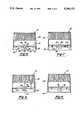
- FIG. 6is a view similar to FIG. 1 showing another embodiment of the invention.
- FIG. 7is a view showing an operating position of the embodiment shown in FIG. 6;
- FIG. 8is a view of still another embodiment of the invention similar to the view in FIG. 1;
- FIG. 9is a view of an operating position of the embodiment shown in FIG. 8.
- the package embodying the inventioncomprises a container 10 and a closure 12.
- the container 10as seen in FIG. 4, has a neck 14 with external threads 16 and the closure 12 has an annular skirt 18 with internal threads 19 complementary to the external threads 16 on the container neck.
- the closure 12preferably is made of plastic such as a high density polyethylene and the container may be made of glass or plastic.
- the closure 12includes a cap 20 forming the skirt 18 and a tamper indicating band 22 which is coaxial with the annular skirt 18.
- the tamper indicating band 22is temporarily attached to the cap skirt 18 by means of a plurality of spaced frangible webs 24.
- the frangible webs 24serve to hold the skirt 18 and band 22 in concentric relationship during application of the closure assembly 12 to the container 10 and are fractured during opening of the package to indicate tampering.
- the tamper indicating band 22has a radially inwardly extending lip 26 complementary to a stop means or flange 28 on the neck 14 immediately below the external threads 16, as best seen in FIG. 4.
- the tamper indicating band 22also is provided with a plurality of platforms 30 disposed on the inclined top surface 31 of the tamper indicating band in space 32 formed between the bottom of the skirt 18 and the top 31 of the tamper indicating band 22.
- the tops of the platforms 30are normally spaced from the bottom of the skirt 18.
- the tamper indicating band 22is attached to the skirt 18 by permanent means in the form of a tether structure 36.
- the tether structure 36is formed by a circumferential slot 38 which extends through an arc of approximately 45°-50 degrees.
- the portion of the tamper indicating band above the slot 38is connected to cap skirt 18 by a pair of permanent tether bands 40 separated from each other by an axially extending slot 42 best seen in FIGS. 1-3.
- the portion of the tamper indicating band 22 below the slot 38is narrower and more flexible than the remainder of the band 22 and is lifted over the hinge 28 on the container neck so that when the external threads 18 and internal threads 19 are fully unthreaded and disengaged, the cap can be used to pull the remainder of the tamper indicating band 22 from engagement with the flange 28 so that the entire closure 20, including the annular skirt 18 and tamper indicating band 22 are freed from the container neck.
- the slot 42serves the purpose of assuring that the tether structure 36 forms a permanent means of attachment between the cap and the tamper indicating band 22.
- the properties of some plastic materials used to make closuresare such that any flaws or fractures that exist, tend to migrate or progress such as a crack in a pane of glass. If a flaw in one or the other of the tether bands 40 should occur, the slot 42 prevents any circumferential migration of any crack and maintains the integrity of the remaining tether band 40 which of itself is strong enough to lift the tamper indicating band 22 over the flange 28.
- platforms 30are located at the ends of the slot 38 to insure transfer of axial forces from the cap skirt 18 to the band 22 and lip 26 as the closure 12 is positioned on a container 10 to close it.
- a tether structure 50is formed in the tamper indicating band 22 by an L-shaped slot 52 which is formed by a circumferentially extending slot portion 54 and an axial slot portion 56 to form a circumferential extending tang 58.
- the tang 58merges with a permanent tether portion 60 which is formed integrally with cap 20.
- the remaining portions of the closure 12are the same as those in the first embodiment.
- initial axial movement of the cap skirt 18 resulting from unthreadingcauses breakage of all of the frangible webs 24 during which time the axial movement relative to the axially stationary tamper indicating band 22 causes flexing of the tether 60 and tang 58 to assume the position shown in FIG. 7.
- the tether structure 50 formed by the tang 58 and tether portion 60becomes sufficiently taut so that further unthreading of the cap and the resultant axial movement of the cap 20 tends to pull the portion of the tamper indicating band 22 adjacent to the tether structure 50 over the flange 28 to relieve the tension in the tamper indicating band 22 so that it can be stripped over the flange 28 and from the container 10.
- FIGS. 8 and 9Another embodiment of the invention is seen in FIGS. 8 and 9 in which a tether structure 70 generally similar to the tether structure 50 in FIGS. 6 and 7 is employed.
- the tether structure 70includes an L-shaped slot 72 in the tamper indicating band 22 which forms a circumferentially extending tang 74 attached to the skirt 18 of the cap 20 by means of a pair of permanent webs 76.
- FIGS. 8 and 9operates in substantially the same manner as the embodiment in FIGS. 6 and 7 and has the further advantage that the circumferential crack in either of the permanent webs 76 will leave the remaining webs 76 intact to pull the tang 74 and tamper indicating band 22 over the flange 28 upon unthreading of the cap.
Landscapes
- Engineering & Computer Science (AREA)
- Mechanical Engineering (AREA)
- Closures For Containers (AREA)
Abstract
Description
Claims (11)
Priority Applications (1)
| Application Number | Priority Date | Filing Date | Title |
|---|---|---|---|
| US07/877,812US5246125A (en) | 1992-05-04 | 1992-05-04 | Tamper indicating closure with attached tamper indicating band |
Applications Claiming Priority (1)
| Application Number | Priority Date | Filing Date | Title |
|---|---|---|---|
| US07/877,812US5246125A (en) | 1992-05-04 | 1992-05-04 | Tamper indicating closure with attached tamper indicating band |
Publications (1)
| Publication Number | Publication Date |
|---|---|
| US5246125Atrue US5246125A (en) | 1993-09-21 |
Family
ID=25370778
Family Applications (1)
| Application Number | Title | Priority Date | Filing Date |
|---|---|---|---|
| US07/877,812Expired - LifetimeUS5246125A (en) | 1992-05-04 | 1992-05-04 | Tamper indicating closure with attached tamper indicating band |
Country Status (1)
| Country | Link |
|---|---|
| US (1) | US5246125A (en) |
Cited By (41)
| Publication number | Priority date | Publication date | Assignee | Title |
|---|---|---|---|---|
| EP0703155A1 (en)* | 1994-09-20 | 1996-03-27 | PELLICONI ABRUZZO S.r.l. | Plastic closure with tamper evident ring |
| WO1996029257A1 (en) | 1995-03-22 | 1996-09-26 | Precision Valve Corporation | Tamper-evident closure with captive band |
| US5609263A (en)* | 1993-09-22 | 1997-03-11 | Perchepied; Jacques | Threaded bottle cap |
| US5711447A (en)* | 1994-09-28 | 1998-01-27 | The Coca-Cola Company | Easy-open resealable can-end and closure therefor |
| WO1998030462A1 (en)* | 1997-01-09 | 1998-07-16 | Cct Creative Closure Technology Gmbh | Plastics screw-type cap for bottles, provided with a tamperproof strip |
| US6089390A (en)* | 1992-07-16 | 2000-07-18 | Closures And Packaging Services Limited | Tamper evident closure |
| US6527132B1 (en) | 1997-07-14 | 2003-03-04 | Closures And Packaging Services Limited | Closure with extended seal member |
| US20030192892A1 (en)* | 2002-04-16 | 2003-10-16 | M.F.V Co., Ltd. | Case |
| US6793082B1 (en)* | 1997-10-30 | 2004-09-21 | International Plastics And Equipment Corporation | Snap-on screw-off closure for use in combination with a container |
| US20050045578A1 (en)* | 2001-09-20 | 2005-03-03 | Wolfhard Schwarz | Screw cap |
| US6931821B2 (en) | 2003-07-29 | 2005-08-23 | Evergreen Industries, Inc. | Tamper evident vial cap and integrity assurance method |
| US20060060555A1 (en)* | 1997-08-01 | 2006-03-23 | Portola Packaging, Inc. | Tamper evident bottle cap |
| US20060091100A1 (en)* | 2004-10-29 | 2006-05-04 | Geho Jeffrey E | Snap-top closure device |
| US7228979B2 (en) | 1997-10-30 | 2007-06-12 | International Plastics And Equipment Corp. | Snap-on screw-off closure with retaining member for tamper-indicating band |
| US20070267100A1 (en)* | 2006-05-08 | 2007-11-22 | Spear Gregory N | Bottle Cap and Method of Use With a Liquid Dispensing Apparatus and System |
| JP2008056246A (en)* | 2006-08-29 | 2008-03-13 | Japan Crown Cork Co Ltd | Cap having bottle retaining function |
| US20080164235A1 (en)* | 2007-01-05 | 2008-07-10 | Phoenix Closures, Inc. | Tamper-evident closure and container combination |
| EP2938553A4 (en)* | 2012-12-27 | 2016-08-03 | Ge Healthcare As | CONTAINER CAP ASSEMBLY WITH DEPRESSION PROOF |
| WO2016160591A1 (en)* | 2015-04-02 | 2016-10-06 | Michael Maguire | Cap for container |
| US10654625B2 (en) | 2018-10-12 | 2020-05-19 | Closure Systems International Inc. | Twist and flip lock closure |
| IT201900001381A1 (en)* | 2019-01-30 | 2020-07-30 | Sacmi | Cap to close a container |
| US10836544B2 (en) | 2018-05-09 | 2020-11-17 | Silgan White Cap LLC | Closure with hinge |
| WO2021013370A1 (en)* | 2019-07-23 | 2021-01-28 | Obrist Closures Switzerland Gmbh | Closure |
| US20210094736A1 (en)* | 2015-04-02 | 2021-04-01 | ThisCap, Inc. | Tool for manufacturing a cap for a container |
| US20210171257A1 (en)* | 2019-12-04 | 2021-06-10 | Société Lorraine De Capsules Métalliques-Manufacture De Bouchage | Screw capping device intended to remain tethered to a container after opening of the container |
| US11059633B2 (en) | 2019-10-31 | 2021-07-13 | Cheer Pack North America | Flip-top closure for container |
| JP2021133978A (en)* | 2020-02-28 | 2021-09-13 | 凸版印刷株式会社 | Hinge cap |
| EP3976488A1 (en)* | 2019-07-22 | 2022-04-06 | Sacmi Cooperativa Meccanici Imola Societa' Cooperativa | A cap for closing a container, a combination of a cap and a neck |
| US11312544B2 (en)* | 2020-03-30 | 2022-04-26 | ThisCap, Inc. | Cap for container |
| US11332290B2 (en)* | 2015-04-02 | 2022-05-17 | ThisCap, Inc. | Cap for container |
| US20220153483A1 (en)* | 2019-03-11 | 2022-05-19 | Alpla Werke Alwin Lehner Gmbh & Co. Kg | Container closure |
| US11485550B2 (en)* | 2019-05-13 | 2022-11-01 | Husky Injection Molding Systems Ltd. | Closure device for a container |
| US11535436B2 (en) | 2020-03-27 | 2022-12-27 | Sacmi Cooperativa Meccanici Imola Societa' Cooperativa | Combination of a cap for a container and a neck of the container |
| US20230174275A1 (en)* | 2020-08-07 | 2023-06-08 | Niagara Bottling, Llc | Single anchor closure |
| US11697534B2 (en) | 2019-07-22 | 2023-07-11 | Sacmi Cooperativa Meccanici Imola Societa' Cooperativa | Cap for a container, combination of a cap and a neck of the container and its production method |
| EP3784585B1 (en) | 2018-04-26 | 2023-07-12 | Obrist Closures Switzerland GmbH | Closure |
| US20230303294A1 (en)* | 2020-08-11 | 2023-09-28 | Guala Pack S.P.A. | Closure for a spout in a thin-walled package |
| US11851247B2 (en) | 2018-07-11 | 2023-12-26 | Closure Systems International Inc. | Twist and flip closure |
| US12122561B2 (en) | 2020-01-16 | 2024-10-22 | Closure Systems International Inc. | Package with tethered closure |
| US20240425252A1 (en)* | 2021-08-27 | 2024-12-26 | Jose Francisco Gonzalez Sanchez | Screw-on closing cap for containers and a container provided with said cap |
| WO2025088172A1 (en) | 2023-10-26 | 2025-05-01 | Affaba & Ferrari S.R.L. | Beverage cap with integral tether for multiple capturing positions |
Citations (9)
| Publication number | Priority date | Publication date | Assignee | Title |
|---|---|---|---|---|
| US4346811A (en)* | 1978-03-28 | 1982-08-31 | Captocap Limited | Pilfer-proof closure cap of plastic material |
| US4394918A (en)* | 1981-02-11 | 1983-07-26 | Charles A. Breskin Assoc. Inc. | Screw cap with tamper-proof hold ring |
| US4432461A (en)* | 1982-04-09 | 1984-02-21 | Owens-Illinois, Inc. | Tamper indicating package |
| US4480761A (en)* | 1982-07-14 | 1984-11-06 | Albert Obrist Ag | Tamper indicating closure for a container |
| US4613052A (en)* | 1985-04-29 | 1986-09-23 | Owens-Illinois, Inc. | Tamper-indicating closure, container and combination thereof |
| US4664278A (en)* | 1986-06-25 | 1987-05-12 | Owens-Illinois, Inc. | Tamper indicating package |
| US4664279A (en)* | 1984-02-06 | 1987-05-12 | Crown Obrist Ag | Closure cap of plastic material |
| US4913300A (en)* | 1987-01-30 | 1990-04-03 | Walter Wiedmar AG Plastikform | Closure with guarantee ring for containers |
| US5056675A (en)* | 1991-01-18 | 1991-10-15 | Sunbeam Plastics Corporation | Tether web ratchet drive tamper indicating band closure |
- 1992
- 1992-05-04USUS07/877,812patent/US5246125A/ennot_activeExpired - Lifetime
Patent Citations (9)
| Publication number | Priority date | Publication date | Assignee | Title |
|---|---|---|---|---|
| US4346811A (en)* | 1978-03-28 | 1982-08-31 | Captocap Limited | Pilfer-proof closure cap of plastic material |
| US4394918A (en)* | 1981-02-11 | 1983-07-26 | Charles A. Breskin Assoc. Inc. | Screw cap with tamper-proof hold ring |
| US4432461A (en)* | 1982-04-09 | 1984-02-21 | Owens-Illinois, Inc. | Tamper indicating package |
| US4480761A (en)* | 1982-07-14 | 1984-11-06 | Albert Obrist Ag | Tamper indicating closure for a container |
| US4664279A (en)* | 1984-02-06 | 1987-05-12 | Crown Obrist Ag | Closure cap of plastic material |
| US4613052A (en)* | 1985-04-29 | 1986-09-23 | Owens-Illinois, Inc. | Tamper-indicating closure, container and combination thereof |
| US4664278A (en)* | 1986-06-25 | 1987-05-12 | Owens-Illinois, Inc. | Tamper indicating package |
| US4913300A (en)* | 1987-01-30 | 1990-04-03 | Walter Wiedmar AG Plastikform | Closure with guarantee ring for containers |
| US5056675A (en)* | 1991-01-18 | 1991-10-15 | Sunbeam Plastics Corporation | Tether web ratchet drive tamper indicating band closure |
Cited By (77)
| Publication number | Priority date | Publication date | Assignee | Title |
|---|---|---|---|---|
| US6705479B2 (en) | 1992-07-16 | 2004-03-16 | Closures And Packaging Services Limited | Tamper evident closure |
| US6089390A (en)* | 1992-07-16 | 2000-07-18 | Closures And Packaging Services Limited | Tamper evident closure |
| US6325225B1 (en) | 1992-07-16 | 2001-12-04 | Closures And Packaging Services Limited | Tamper evident closure |
| US5609263A (en)* | 1993-09-22 | 1997-03-11 | Perchepied; Jacques | Threaded bottle cap |
| EP0703155A1 (en)* | 1994-09-20 | 1996-03-27 | PELLICONI ABRUZZO S.r.l. | Plastic closure with tamper evident ring |
| US5711447A (en)* | 1994-09-28 | 1998-01-27 | The Coca-Cola Company | Easy-open resealable can-end and closure therefor |
| WO1996029257A1 (en) | 1995-03-22 | 1996-09-26 | Precision Valve Corporation | Tamper-evident closure with captive band |
| US5676269A (en)* | 1995-03-22 | 1997-10-14 | Closures And Packaging Services Limited | Tamper-evident closure with captive band |
| RU2139230C1 (en)* | 1995-03-22 | 1999-10-10 | Кложурес энд Пэкэджинг Сервисис Лимитед | Cap with opening indicating strip |
| WO1998030462A1 (en)* | 1997-01-09 | 1998-07-16 | Cct Creative Closure Technology Gmbh | Plastics screw-type cap for bottles, provided with a tamperproof strip |
| US6264052B1 (en) | 1997-01-09 | 2001-07-24 | Cct Creative Closure Technology Gmbh | Screw-type cap including an expandable tamperproof strip |
| RU2199476C2 (en)* | 1997-01-09 | 2003-02-27 | Ккт Криэйтив Клоужер Текнолоджи Гмбх | Plastic screw cap for bottles with lockring |
| US6991123B2 (en) | 1997-07-14 | 2006-01-31 | Closures And Packaging Services Limited | Closure with extended seal member |
| US6527132B1 (en) | 1997-07-14 | 2003-03-04 | Closures And Packaging Services Limited | Closure with extended seal member |
| US20090057261A1 (en)* | 1997-08-01 | 2009-03-05 | Mike Xiaoli Ma | Tamper evident bottle cap |
| US20060060555A1 (en)* | 1997-08-01 | 2006-03-23 | Portola Packaging, Inc. | Tamper evident bottle cap |
| US6793082B1 (en)* | 1997-10-30 | 2004-09-21 | International Plastics And Equipment Corporation | Snap-on screw-off closure for use in combination with a container |
| US7228979B2 (en) | 1997-10-30 | 2007-06-12 | International Plastics And Equipment Corp. | Snap-on screw-off closure with retaining member for tamper-indicating band |
| US20050045578A1 (en)* | 2001-09-20 | 2005-03-03 | Wolfhard Schwarz | Screw cap |
| US7712619B2 (en)* | 2001-09-20 | 2010-05-11 | Alcoa Deutschland Gmbh | Screw cap |
| US20030192892A1 (en)* | 2002-04-16 | 2003-10-16 | M.F.V Co., Ltd. | Case |
| US6923335B2 (en)* | 2002-04-16 | 2005-08-02 | M.F.V. Co., Ltd. | Case |
| US6931821B2 (en) | 2003-07-29 | 2005-08-23 | Evergreen Industries, Inc. | Tamper evident vial cap and integrity assurance method |
| US20060091100A1 (en)* | 2004-10-29 | 2006-05-04 | Geho Jeffrey E | Snap-top closure device |
| US7789254B2 (en)* | 2004-10-29 | 2010-09-07 | Novelis Inc. | Snap-top closure device |
| US20070267100A1 (en)* | 2006-05-08 | 2007-11-22 | Spear Gregory N | Bottle Cap and Method of Use With a Liquid Dispensing Apparatus and System |
| JP2008056246A (en)* | 2006-08-29 | 2008-03-13 | Japan Crown Cork Co Ltd | Cap having bottle retaining function |
| US20080164235A1 (en)* | 2007-01-05 | 2008-07-10 | Phoenix Closures, Inc. | Tamper-evident closure and container combination |
| US8353413B2 (en)* | 2007-01-05 | 2013-01-15 | Phoenix Closures, Inc. | Tamper-evident closure and container combination |
| EP2938553A4 (en)* | 2012-12-27 | 2016-08-03 | Ge Healthcare As | CONTAINER CAP ASSEMBLY WITH DEPRESSION PROOF |
| US10913580B2 (en) | 2012-12-27 | 2021-02-09 | Ge Healthcare As | Tamper-evident container cap assembly |
| CN110329652A (en)* | 2015-04-02 | 2019-10-15 | 麦奎尔·迈可 | lids for containers |
| US12371235B2 (en)* | 2015-04-02 | 2025-07-29 | ThisCap, Inc. | Tool for manufacturing a cap for a container |
| JP2018510825A (en)* | 2015-04-02 | 2018-04-19 | マイケル マグワイアMAGUIRE, Michael | Lid for container |
| CN107531369B (en)* | 2015-04-02 | 2019-06-21 | 麦奎尔·迈可 | cover for container |
| AU2016243513B2 (en)* | 2015-04-02 | 2019-07-11 | Thiscap Inc. | Cap for container |
| US9643762B2 (en) | 2015-04-02 | 2017-05-09 | Michael Joseph MAGUIRE | Cap for container |
| JP2021185102A (en)* | 2015-04-02 | 2021-12-09 | マイケル マグワイアMAGUIRE, Michael | Closure for the container |
| CN107531369A (en)* | 2015-04-02 | 2018-01-02 | 麦奎尔·迈可 | lids for containers |
| US11332290B2 (en)* | 2015-04-02 | 2022-05-17 | ThisCap, Inc. | Cap for container |
| CN110329652B (en)* | 2015-04-02 | 2021-01-19 | 麦奎尔·迈可 | Cover for container |
| US20210094736A1 (en)* | 2015-04-02 | 2021-04-01 | ThisCap, Inc. | Tool for manufacturing a cap for a container |
| WO2016160591A1 (en)* | 2015-04-02 | 2016-10-06 | Michael Maguire | Cap for container |
| EP3784585B1 (en) | 2018-04-26 | 2023-07-12 | Obrist Closures Switzerland GmbH | Closure |
| US11814224B2 (en) | 2018-05-09 | 2023-11-14 | Silgan White Cap LLC | Closure with hinge |
| US10836544B2 (en) | 2018-05-09 | 2020-11-17 | Silgan White Cap LLC | Closure with hinge |
| US11851247B2 (en) | 2018-07-11 | 2023-12-26 | Closure Systems International Inc. | Twist and flip closure |
| US10654625B2 (en) | 2018-10-12 | 2020-05-19 | Closure Systems International Inc. | Twist and flip lock closure |
| US10981700B2 (en) | 2018-10-12 | 2021-04-20 | Closure Systems International Inc. | Twist and flip lock closure |
| IT201900001381A1 (en)* | 2019-01-30 | 2020-07-30 | Sacmi | Cap to close a container |
| US20220153483A1 (en)* | 2019-03-11 | 2022-05-19 | Alpla Werke Alwin Lehner Gmbh & Co. Kg | Container closure |
| US12227337B2 (en)* | 2019-03-11 | 2025-02-18 | Alpla Werke Alwin Lehner Gmbh & Co. Kg | Container closure |
| US11485550B2 (en)* | 2019-05-13 | 2022-11-01 | Husky Injection Molding Systems Ltd. | Closure device for a container |
| US12214945B2 (en) | 2019-05-13 | 2025-02-04 | Husky Injection Molding Systems Ltd. | Closure device for a container |
| US12103749B2 (en)* | 2019-05-13 | 2024-10-01 | Husky Injection Molding Systems Ltd. | Closure device for a container |
| US12214935B2 (en) | 2019-07-22 | 2025-02-04 | Sacmi Cooperativa Meccanici Imola Societa'cooperativa | Cap for closing a container, a combination of a cap and a neck |
| EP3976488A1 (en)* | 2019-07-22 | 2022-04-06 | Sacmi Cooperativa Meccanici Imola Societa' Cooperativa | A cap for closing a container, a combination of a cap and a neck |
| US11697534B2 (en) | 2019-07-22 | 2023-07-11 | Sacmi Cooperativa Meccanici Imola Societa' Cooperativa | Cap for a container, combination of a cap and a neck of the container and its production method |
| US12097998B2 (en) | 2019-07-23 | 2024-09-24 | Obrist Closures Switzerland Gmbh | Closure |
| WO2021013370A1 (en)* | 2019-07-23 | 2021-01-28 | Obrist Closures Switzerland Gmbh | Closure |
| CN114144364A (en)* | 2019-07-23 | 2022-03-04 | 奥布里斯特封闭瑞士有限公司 | Closure member |
| US11059633B2 (en) | 2019-10-31 | 2021-07-13 | Cheer Pack North America | Flip-top closure for container |
| US20210171257A1 (en)* | 2019-12-04 | 2021-06-10 | Société Lorraine De Capsules Métalliques-Manufacture De Bouchage | Screw capping device intended to remain tethered to a container after opening of the container |
| US11591147B2 (en)* | 2019-12-04 | 2023-02-28 | Société Lorraine De Capsules Métalliques-Manufacture De Bouchage | Screw capping device intended to remain tethered to a container after opening of the container |
| EP3838790A1 (en)* | 2019-12-04 | 2021-06-23 | Société Lorraine de Capsules Metalliques - Manufacture de Bouchage | Screw cap device intended to be attached to a container after opening of the container |
| FR3104144A1 (en)* | 2019-12-04 | 2021-06-11 | Société Lorraine De Capsules Métalliques-Manufacture De Bouchage | Screw closure device intended to remain attached to a container after opening the container. |
| US12122561B2 (en) | 2020-01-16 | 2024-10-22 | Closure Systems International Inc. | Package with tethered closure |
| JP2021133978A (en)* | 2020-02-28 | 2021-09-13 | 凸版印刷株式会社 | Hinge cap |
| US11535436B2 (en) | 2020-03-27 | 2022-12-27 | Sacmi Cooperativa Meccanici Imola Societa' Cooperativa | Combination of a cap for a container and a neck of the container |
| US11312544B2 (en)* | 2020-03-30 | 2022-04-26 | ThisCap, Inc. | Cap for container |
| US20220212836A1 (en)* | 2020-03-30 | 2022-07-07 | ThisCap, Inc. | Cap for container |
| US12351366B2 (en)* | 2020-03-30 | 2025-07-08 | ThisCap, Inc. | Cap for container |
| US11975891B2 (en)* | 2020-08-07 | 2024-05-07 | Niagara Bottling, Llc | Single anchor closure |
| US20230174275A1 (en)* | 2020-08-07 | 2023-06-08 | Niagara Bottling, Llc | Single anchor closure |
| US20230303294A1 (en)* | 2020-08-11 | 2023-09-28 | Guala Pack S.P.A. | Closure for a spout in a thin-walled package |
| US20240425252A1 (en)* | 2021-08-27 | 2024-12-26 | Jose Francisco Gonzalez Sanchez | Screw-on closing cap for containers and a container provided with said cap |
| WO2025088172A1 (en) | 2023-10-26 | 2025-05-01 | Affaba & Ferrari S.R.L. | Beverage cap with integral tether for multiple capturing positions |
Similar Documents
| Publication | Publication Date | Title |
|---|---|---|
| US5246125A (en) | Tamper indicating closure with attached tamper indicating band | |
| US5080245A (en) | Bidirectional scoring | |
| AU722794B2 (en) | Sealing device and container | |
| US5080246A (en) | Closure having a spring open tamper evidencing band | |
| US4432461A (en) | Tamper indicating package | |
| AU719199B2 (en) | Sealing device and container | |
| US4664278A (en) | Tamper indicating package | |
| JP3382964B2 (en) | Fraudulent plastic closure | |
| US6276543B1 (en) | Vented composite closure | |
| CA1283629C (en) | Tamper-indicating closure, container and combination thereof | |
| US5295600A (en) | Tamper indicating closure | |
| US5450973A (en) | Tamper-evident closure apparatus | |
| US5129530A (en) | Tamper indicating closure | |
| US4643321A (en) | Tamper indicating band for threaded cap | |
| KR100436168B1 (en) | Opening check with stop band | |
| AU758125B2 (en) | Tamper indicating closure with foldable tab | |
| US4653657A (en) | Tamper indicating package | |
| CA1287326C (en) | Scoring arrangement for a tamper-indicating plastic closure | |
| US5167335A (en) | Tamper-indicating plastic closure | |
| US4527704A (en) | Tamper indicating package | |
| US4746026A (en) | Tamper-proof closure | |
| EP0010837A1 (en) | Pilferproof closure and container assembled with such closure | |
| US5484071A (en) | Tamper indicating ring construction for closures | |
| US5358131A (en) | Tamper-indicating plastic closure with segemented pilfer band | |
| US6116444A (en) | Plastic closure cap |
Legal Events
| Date | Code | Title | Description |
|---|---|---|---|
| AS | Assignment | Owner name:SUNBEAM PLASTICS CORPORATION, INDIANA Free format text:ASSIGNMENT OF ASSIGNORS INTEREST.;ASSIGNOR:JULIAN, RANDALL K.;REEL/FRAME:006118/0511 Effective date:19920330 | |
| STCF | Information on status: patent grant | Free format text:PATENTED CASE | |
| FEPP | Fee payment procedure | Free format text:PAYOR NUMBER ASSIGNED (ORIGINAL EVENT CODE: ASPN); ENTITY STATUS OF PATENT OWNER: LARGE ENTITY | |
| FPAY | Fee payment | Year of fee payment:4 | |
| FPAY | Fee payment | Year of fee payment:8 | |
| FPAY | Fee payment | Year of fee payment:12 | |
| AS | Assignment | Owner name:REXAM CLOSURES AND CONTAINERS INC., NORTH CAROLINA Free format text:ASSIGNMENT OF ASSIGNORS INTEREST;ASSIGNOR:SUNBEAM PLASTICS CORPORATION;REEL/FRAME:028539/0163 Effective date:20110815 | |
| AS | Assignment | Owner name:REXAM CLOSURES LLC, NORTH CAROLINA Free format text:ASSIGNMENT OF ASSIGNORS INTEREST;ASSIGNOR:REXAM CLOSURES AND CONTAINERS, INC.;REEL/FRAME:028680/0204 Effective date:20110815 | |
| AS | Assignment | Owner name:BERRY PLASTICS CORPORATION, INDIANA Free format text:ASSIGNMENT OF ASSIGNORS INTEREST;ASSIGNOR:REXAM CLOSURES LLC;REEL/FRAME:028715/0215 Effective date:20120529 |