US5246109A - Package for an active medical device - Google Patents
Package for an active medical deviceDownload PDFInfo
- Publication number
- US5246109A US5246109AUS07/888,569US88856992AUS5246109AUS 5246109 AUS5246109 AUS 5246109AUS 88856992 AUS88856992 AUS 88856992AUS 5246109 AUS5246109 AUS 5246109A
- Authority
- US
- United States
- Prior art keywords
- opening
- recess
- wall
- package
- band
- Prior art date
- Legal status (The legal status is an assumption and is not a legal conclusion. Google has not performed a legal analysis and makes no representation as to the accuracy of the status listed.)
- Expired - Fee Related
Links
- 238000012360testing methodMethods0.000claimsabstractdescription26
- 230000003287optical effectEffects0.000claimsabstractdescription14
- 230000036512infertilityEffects0.000claimsabstractdescription8
- 230000008054signal transmissionEffects0.000claimsabstractdescription7
- 230000006835compressionEffects0.000claimsabstractdescription5
- 238000007906compressionMethods0.000claimsabstractdescription5
- 239000004020conductorSubstances0.000claimsdescription16
- 230000005540biological transmissionEffects0.000claimsdescription5
- 239000012858resilient materialSubstances0.000claimsdescription4
- 239000012780transparent materialSubstances0.000claimsdescription4
- 238000000034methodMethods0.000abstractdescription10
- 230000004888barrier functionEffects0.000abstractdescription9
- 238000010998test methodMethods0.000abstractdescription3
- 239000008280bloodSubstances0.000description8
- 210000004369bloodAnatomy0.000description8
- 239000000835fiberSubstances0.000description7
- 238000001727in vivoMethods0.000description7
- 230000001268conjugating effectEffects0.000description4
- 238000004806packaging method and processMethods0.000description4
- 229920000642polymerPolymers0.000description4
- 239000000463materialSubstances0.000description3
- 239000000523sampleSubstances0.000description3
- 239000004698PolyethyleneSubstances0.000description2
- 229920000690TyvekPolymers0.000description2
- 239000000853adhesiveSubstances0.000description2
- 230000001070adhesive effectEffects0.000description2
- -1polyethylenePolymers0.000description2
- 229920000573polyethylenePolymers0.000description2
- 239000000126substanceSubstances0.000description2
- 229910001369BrassInorganic materials0.000description1
- 229910000906BronzeInorganic materials0.000description1
- 239000004793PolystyreneSubstances0.000description1
- BQCADISMDOOEFD-UHFFFAOYSA-NSilverChemical compound[Ag]BQCADISMDOOEFD-UHFFFAOYSA-N0.000description1
- ATJFFYVFTNAWJD-UHFFFAOYSA-NTinChemical compound[Sn]ATJFFYVFTNAWJD-UHFFFAOYSA-N0.000description1
- 239000004775TyvekSubstances0.000description1
- 238000010521absorption reactionMethods0.000description1
- 239000012491analyteSubstances0.000description1
- 239000011324beadSubstances0.000description1
- 238000004159blood analysisMethods0.000description1
- 239000010951brassSubstances0.000description1
- 239000010974bronzeSubstances0.000description1
- 230000003749cleanlinessEffects0.000description1
- 238000010276constructionMethods0.000description1
- 238000011109contaminationMethods0.000description1
- KUNSUQLRTQLHQQ-UHFFFAOYSA-Ncopper tinChemical compound[Cu].[Sn]KUNSUQLRTQLHQQ-UHFFFAOYSA-N0.000description1
- 238000009826distributionMethods0.000description1
- 239000000428dustSubstances0.000description1
- 238000001125extrusionMethods0.000description1
- 239000003269fluorescent indicatorSubstances0.000description1
- 239000003292glueSubstances0.000description1
- PCHJSUWPFVWCPO-UHFFFAOYSA-NgoldChemical compound[Au]PCHJSUWPFVWCPO-UHFFFAOYSA-N0.000description1
- 239000010931goldSubstances0.000description1
- 229910052737goldInorganic materials0.000description1
- 239000004922lacquerSubstances0.000description1
- 238000004519manufacturing processMethods0.000description1
- 238000005259measurementMethods0.000description1
- 239000012528membraneSubstances0.000description1
- 239000002184metalSubstances0.000description1
- 229910052751metalInorganic materials0.000description1
- 238000012544monitoring processMethods0.000description1
- 239000013307optical fiberSubstances0.000description1
- 239000004033plasticSubstances0.000description1
- 229920003023plasticPolymers0.000description1
- 229920002223polystyrenePolymers0.000description1
- 239000004065semiconductorSubstances0.000description1
- 229920002379silicone rubberPolymers0.000description1
- 239000004945silicone rubberSubstances0.000description1
- 229910052709silverInorganic materials0.000description1
- 239000004332silverSubstances0.000description1
- 239000002904solventSubstances0.000description1
- 230000001954sterilising effectEffects0.000description1
- 238000004659sterilization and disinfectionMethods0.000description1
- 238000003466weldingMethods0.000description1
Images


Classifications
- A—HUMAN NECESSITIES
- A61—MEDICAL OR VETERINARY SCIENCE; HYGIENE
- A61B—DIAGNOSIS; SURGERY; IDENTIFICATION
- A61B5/00—Measuring for diagnostic purposes; Identification of persons
- A61B5/145—Measuring characteristics of blood in vivo, e.g. gas concentration or pH-value ; Measuring characteristics of body fluids or tissues, e.g. interstitial fluid or cerebral tissue
- A—HUMAN NECESSITIES
- A61—MEDICAL OR VETERINARY SCIENCE; HYGIENE
- A61B—DIAGNOSIS; SURGERY; IDENTIFICATION
- A61B50/00—Containers, covers, furniture or holders specially adapted for surgical or diagnostic appliances or instruments, e.g. sterile covers
- A61B50/30—Containers specially adapted for packaging, protecting, dispensing, collecting or disposing of surgical or diagnostic appliances or instruments
- A—HUMAN NECESSITIES
- A61—MEDICAL OR VETERINARY SCIENCE; HYGIENE
- A61B—DIAGNOSIS; SURGERY; IDENTIFICATION
- A61B50/00—Containers, covers, furniture or holders specially adapted for surgical or diagnostic appliances or instruments, e.g. sterile covers
- A61B2050/005—Containers, covers, furniture or holders specially adapted for surgical or diagnostic appliances or instruments, e.g. sterile covers with a lid or cover
- A—HUMAN NECESSITIES
- A61—MEDICAL OR VETERINARY SCIENCE; HYGIENE
- A61B—DIAGNOSIS; SURGERY; IDENTIFICATION
- A61B50/00—Containers, covers, furniture or holders specially adapted for surgical or diagnostic appliances or instruments, e.g. sterile covers
- A61B50/30—Containers specially adapted for packaging, protecting, dispensing, collecting or disposing of surgical or diagnostic appliances or instruments
- A61B50/33—Trays
- Y—GENERAL TAGGING OF NEW TECHNOLOGICAL DEVELOPMENTS; GENERAL TAGGING OF CROSS-SECTIONAL TECHNOLOGIES SPANNING OVER SEVERAL SECTIONS OF THE IPC; TECHNICAL SUBJECTS COVERED BY FORMER USPC CROSS-REFERENCE ART COLLECTIONS [XRACs] AND DIGESTS
- Y10—TECHNICAL SUBJECTS COVERED BY FORMER USPC
- Y10S—TECHNICAL SUBJECTS COVERED BY FORMER USPC CROSS-REFERENCE ART COLLECTIONS [XRACs] AND DIGESTS
- Y10S439/00—Electrical connectors
- Y10S439/912—Electrical connectors with testing means
Definitions
- This inventionrelates to a package for an active medical device and the method of assembly and testing thereof. More particularly, a structure that contains the active medical device yet, allows testing without compromise of the sterile barrier provided by the package.
- Described hereinare a package for the active medical devices and methods of manufacture and/or use not found in the literature or practiced in the field.
- the literatureis of interest for its teachings of the knowledge of skilled artisans at the time of this invention of the package for the active medical device and method of assembly and testing thereof.
- Disposable medical devicesare sold in groups of like size and type which are typically carried in an over carton in a dozen or more individually packaged, identical devices. A package can be removed from the over carton and opened to obtain a single disposable device. Individual packaging maintains a sterile barrier for each disposable medical device. Consequently, the package for each should be inexpensive, easy to open without contamination of the product and structurally adequate to protect the sterility of the product prior to use.
- top or coverwith printed product information as, for example, product size, type, name of manufacturer, instructions and the like.
- the top or coveris usually a thin sheet of extrusion coated paper having a polyethylene layer and a heat sealable lacquer layer.
- the paperis called Tyvek paper and the polyethylene is added for tear resistance.
- the other or second component of the often used packageis a drawn semi rigid tub which has a recess for receiving the product and a flange for supporting the top or cover.
- the tubis thermal formed from semi rigid polymer sheet which is heated and drawn such that the depth of the recess is no more than one and one-half times the width. Products which are wider than they are deep have to be packed sideways, or the package has to be drawn less than required for efficient use of the drawn polystyrene material.
- the flangeis the thickest part of the formed tub in that it is not drawn and the corners of the recess are the thinnest area because they are stretched the most.
- a ratio of flange thickness to corner thickness of six to oneis about the maximum amount of thinning that can be accomplished with an economical starting thickness for the polymer sheet.
- the flangeprotects the device and provides support during opening.
- the cover and tub flangeare heat sealed to securely enclose the product within the recess of the tub, but a portion along an edge is usually left unsealed in order to provide an area where the top can be peeled from the flange.
- the unsealed portion of the edge of the topcan be fanned away from the edge of the flange and then grasped and peeled away from the heat sealed areas about the rest of the flange.
- the product remaining within the recessis supported thereby during peeling.
- the productcan be accessed without having violated the sterile field of the product, but the use of gloved hands is necessary to maintain sterility. Since the product and package are typically sterilized after assembly but before use, the package has to remain a barrier to microbes and the like until the described opening procedure is performed.
- Active medical devicemay include optical fibers or fiber optic chemical sensors used in vivo as probes; such devices must be sensitive to slight changes in gas or ion concentrations.
- U.S. Pat. No. 4,200,110has a fiber optic probe with an ion permeable membrane enclosure about the distal ends of a pair of fiber optics. Change in color of a pH sensitive dye is detected.
- U.S. Patent No. Re. 31,879has a method for measuring concentration of an analyte in a sample that changes color and/or the intensity of light emitted from a fluorescent indicator attached to the fiber.
- U.S. Pat. No. 5,047,208has an optical sensor for blood gas measurement with a pH sensitive absorption dye between the end of the fiber and a mirror.
- the mirroris located by a tube which carries a mirror spaced from and coaxially aligned with the fiber so the dye can be in the space.
- Blood gas sensorsare typically packaged in a vessel filled with solution and then sealed in a sterility protecting package as described.
- the solutionmaintains the chemicals of the sensor fresh and ready to be used.
- Optic and electrical signalsmay be transmitted and returned through miniature conductors pass through a lumen of the blood sensor catheter during use in vivo. The ability to access those miniature conductors before delivery to verify that the sensors are viable and may be used reliably is important to the manner in which active medical devices are handled in their distribution and ultimate application.
- a package for an active medical device with its conductors between the distal and proximal ends thereofpreferably has a film member having a pocket formed therein to define a recess shaped to receive the active medical device.
- the film memberincludes a flange in a plane about the recess and a wall of the recess is most preferably formed as part of the pocket.
- the wallincludes at least a flat portion generally perpendicular to the plane of the flange.
- An openingis preferably in the flat portion for providing access from the recess to the outside of the pocket.
- a lidmay cover the recess of the pocket and enclose the active medical device.
- the lidis most preferably associated with the flange of the film member and thereby contains the active medical device within a sterile field in the recess therein.
- a connectionmay in the preferred embodiment be mounted through the flat portion of the wall of the pocket to assure the sterile field within the lidded recess.
- An inner part and an outer part which conjugate over the opening to seal the opening and insure sterility within the recessis the junction of the preferred embodiment.
- the junctionpreferably includes test means for the conductors of the medical device so that electrical and optical transmissions may pass through the junction without removal of the lid or breach of the sterile field.
- the inner partmay have a central web therein as part of the test means so the active medical device can fit thereto in position to transmit optical signals from light conductors.
- the central webmost preferably has thereabout a plurality of spaced apart electrically conductive pins as another part of the test means which distally couple with the test linkage proximally received. A window of transparent material in the central web permits optical signal transmission therethrough.
- the inner partincludes preferably a band with a brim thereabout so the band fits through the opening and the brim faces the wall about the opening.
- the outer partmay include a collar with a rim thereabout so the collar conjugates with the band of the inner part that extends through the opening and the rim abuts in tight facing relation the wall about the opening.
- the brimmost preferably joins the band to support a gasket thereabout and the gasket may be of a resilient material for compression between the wall and the brim when the inner and outer parts are conjugate.
- Threads about the band of the inner part that extends through the openingmay in the preferred embodiment mate with complimentary threads on the collar of the outer part so that the inner and outer parts may be drawn axially together to compress the gasket against the wall.
- a method of assembly of the package and the junctionincluding the steps of making an opening in the wall of a recess in a package, placing a gasket against a brim and about a band of an inner part of the junction, inserting the band through the opening in the wall so the gasket is flush against the wall, and installing an outer part coaxially about the band whereat it extends beyond the opening to hold the gasket tightly against the wall to form a sterile barrier.
- the added step of threading a collar onto the extended band to secure the outer and inner partsmay be included.
- a method of testing an active medical device in a package that provides a sterile barrier by means of the junctionincluding the steps of inserting the active medical device in a recess within the package, attaching the active medical device to the junction for transmission of signals in and out of the package through the junction, applying signals of light and electric energies to the junction from outside the package, and receiving a modified signal from the active medical device through the junction.
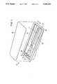
- FIG. 1is a perspective view of the package pocket showing the lid removed above the recess thereof for clarity of the illustration of the active medical device in its packed position before use and connected for testing.
- FIG. 2is a partial top view of package for the active medical device of Figure as would be seen if the lid were completely removed.
- FIG. 3is a partial side view in cross section of the package and the active medical device of FIG. 1 as would be seen if the cross section were taken along line 3--3 in FIG. 1.
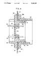
- FIG. 4is an enlarged view in cross section of the portion of the package similar to FIG. 3 and showing the detail of the junction for the active medical device passage through an opening in a wall of the package.
- FIG. 5is an enlarged distal end view of the inner part of the junction as would be seen from inside the package.
- FIG. 6is an enlarged proximal end view of the inner part of the junction or the side that faces the wall of the package.
- FIG. 7is an enlarged proximal end view of the outer part of the junction as would be seen from outside the package.
- FIG. 8is an enlarged distal end view of the outer part of the junction or the side that abuts the wall of the package.
- a package 10 for an active medical device 11 and methods of assembly and testingare disclosed and claimed.
- the claimsare not limited to the structure for the package 1 for the active medical device 11 described and illustrated by way of example and the methods of assembly and testing specifically explained.
- the claimsare to be considered in view of the existing knowledge of skilled artisans in this field prior to the inventions defined by the language of the claims herein as amended or considered in view of that knowledge of skilled artisans.
- FIG. 1a perspective view of the package 10 with a lid 12 positioned above a recess 13 thereof.
- distal and proximalare with respect to the leading end of the active medical device 11, i.e. the part that enters the patient; this is common usage in the medical field.
- the active medical device 11is depicted in its packed position before use and is attached to a junction 14 ready for testing. Skilled artisans will appreciate that the lid 12 will maintain a sterile field within the package 10 and about the active medical device 11.
- the active medical device 11is in a preferred embodiment a blood gas sensing catheter, the active medical device 11 need not be medical and the package 10 need not be sterile.
- any devicecould have an active component and the packaging could be sealed for cleanliness, e.g. a semiconductor in a dust free environment within the packaging.
- the package 10 disclosed in FIG. 1has a film member 15 having a pocket 16 formed therein to define the recess 13 shaped to receive the active medical device 11.
- the film member 15is a polymer sheet that has been vacuumed formed with heat and pressure.
- the preferred materialis a semi rigid and transparent sheet of plastic less than 1 mm. thick.
- the film member 15includes a flange 17 in a plane about the recess 13 and a wall 18 of the recess 13 is most preferably formed as part of the pocket 16.
- the wall 18includes at least a flat portion 19 generally perpendicular to the plane of the flange 17.
- An opening 20is preferably D shaped with a straight edge 21 and is punched or cut into the flat portion 19 for providing access from the recess 13 to the outside of the pocket 16, see FIG. 3.
- the lid 12covers the recess 13 of the pocket 16 and encloses the active medical device
- the lid 12is most preferably gas permeable for use with gas sterilization and Tyvek material is typically used.
- the lid 12is associated with the flange 17 of the film member 15 by heat or solvent activated adhesive to thereby seal and contain the active medical device 11 within a sterile field in the recess 13 therein.
- the disclosure hereinis related to that of commonly assigned patent application Ser. No. 07/887,986, filed May 22, 1992 and entitled "BARRIER FOR A CONNECTOR.”
- the disclosure of that other applicationis incorporated herein and made a part hereof by reference and it describes and shows a particular connector for an in vivo blood gas sensing catheter.
- the preferred embodiment of the present package 10is designed to receive one side of that connector that in vivo blood gas sensing catheter has optic fibers and electrical conductors that terminate proximally in its connector which can be attached to monitoring instrumentation or in the situation disclosed and explained herein the package 10. Consequently, the proximal end of that connector of that in vivo blood gas sensing catheter is attached to the inside portion of the junction 14 in the package 10 as shown in FIGS. 1, 2 and 3.
- the junction 14permits the transmission of optical and electrical signals even though the package 10 is sealed and the sterile field therewithin has not been breached.
- the connector described in the referencehas a conjugating part with terminal face features and is keyed to align the terminal face features.
- the terminal face featuresinclude conductors for electrical circuits and optical paths in the in vivo blood gas sensing catheter.
- a connection 22occurs between the conjugating part and the junction 14 herein when the active medical device 11 of the preferred embodiment is packaged has the features fully conjugated.
- FIG. 2is a partial top view of package 10 for the active medical device 11 of FIG. 1 as would be seen if the lid 12 were completely removed.
- FIG. 3is a partial side view in cross section of package 10 and the active medical device 11 of FIG. 1 as would be seen if the cross section were taken along line 3--3 in FIG. 1. The positioning of the connector conjugating part is shown as it would appear in the preferred embodiment if the active medical device 11 were attached to the junction 14.
- FIG. 4is an enlarged view in cross section of the portion of the package 10 and is similar to Figure in the showing of the details of the junction 14 for the active medical device 11 where the junction 14 passes through the opening 20 in the wall 18 of the package 10, as seen in FIG. 4.
- the inner and outer parts 23 and 24conjugate over the opening 20 to seal the opening 20 and insure sterility within the recess 13.
- the inner and outer parts 23 and 24are molded rigid transparent polymer and form the preferred embodiment of the junction 14.
- the junction 14preferably includes test means 25 for the conductors of the active medical device 11 so that electrical and optical transmissions may pass through the junction 14 without removal of the lid 12 or breach of the sterile field. Specifically and as shown in FIG. 5, an enlarged distal end view of the inner part 23 of the junction 14 as would be seen from inside the package 10, and FIG.
- the inner part 23may have a central web 26 therein as part of the test means 25 so the active medical device 11 can fit thereto in position to transmit optical signals from light conductors.
- a bottom slot 27is provided on the band 28 distally to receive the key of the conjugating part and as used herein bottom is with reference to the package 10 as shown in the Figures, particularly FIG. 1.
- a section 29 of the band 28 facing proximallyis removed to position the band 28 relative to the opening 20 straight edge 21.
- the central web 26has thereabout a plurality of spaced apart electrically conductive pins 30 as another part of the test means 25 which distally couple with the test linkage proximally received.
- the preferred plurality of spaced apart electrically conductive pins 30are conductive metal such as brass, bronze tin plated, silver plated or gold plated; specifically, part number 1364H as made and sold by Prestincert Fasteners Division of Belling Lee Limited of Middlesex, England.
- In the inner part 23there are six spaced apart electrically conductive pins 30 that are parallel to one another with three above and three below the central web 26, as shown in FIGS. 4, 5 and 6.
- the spaced apart electrically conductive pins 30are best seen in side cross section in the enlarged view of FIG. 4 wherein an enlarged center bead 31 sits in a counter sunk hole 32 in inner part 23 and is held therein by heat staking, glue or press fit as desired for assembly ease.
- a window 33 of transparent materialis located in the central web 26 to permit optical signal transmission therethrough.
- the inner part 23includes the band 28 with a brim 34 thereabout so the band 28 fits through the opening 20 and the brim 34 faces the wall 18 about the opening 20 as seen in FIG. 4.
- the outer part 24may include a collar 35 with a rim 35a thereabout so the collar 35 conjugates with the band 28 of the inner part 23 that extends through the opening 20 and the rim 35a abuts in tight facing relation to the wall 18 about the opening 20 also in FIG. 4.
- the brim 34most preferably joins the band 28 to support a gasket 36 thereabout and the gasket 36 may be of a resilient material, such as soft silicone rubber, for compression between the wall 18 and the outer part 24 when the inner and outer parts 23 and 24 are conjugate.
- Threads 37 about the band 28 of the inner part 23 that extends through the opening 20may in the preferred embodiment mate with complimentary threads 38 on the collar 35 of the outer part 24 so that the inner and outer parts 23 and 24 may be drawn axially together to compress the gasket 36 against the wall 18, as in FIG. 4.
- Adhesive or high frequency weldingcan be used to secure the threaded joint between the inner and outer parts 23 and 24.
- FIG. 7is an enlarged proximal end view of the outer part 24 of the junction 14 as would be seen from outside the package 10. There are three notches 39 shown in FIG. 7, spaced about the collar 35 and are useful with a spanner tool when compressing the gasket 36 by tightening the threads 37 and 38 between the collar 35 and band 28.
- FIG. 8is an enlarged distal end view of the outer part 24 of the junction 14 showing the side that abuts the wall 18 of the package 10.
- a method of assembly of the package 10 and the junction 14including the steps of making the opening 20 in the wall 18 of the recess 13 in the package 10, placing the gasket 36 against the wall 18 and about the band 28 of the inner part 23 of the junction 14, inserting the band 28 through the opening 20 in the wall 18 so the gasket 36 is flush against the wall 18, and installing the outer part 24 coaxially about the band 28 whereat it extends beyond the opening 20 to hold the gasket 36 tightly against the wall 18 to form a sterile barrier.
- the added step of threading the collar 35 onto the extended band 28 to secure the outer and inner parts 23 and 24may be included.
- a method of testing the active medical device 11 in the package 10 that provides a sterile barrier by means of the junction 14including the steps of inserting the active medical device 11 into the recess 13 within the package 10, attaching the active medical device 11 to the junction 14 for thereafter allowing transmission of signals into and out of the package 10 through the junction 14, applying signals of light and electric energies to the junction 14 from outside the package 10, and receiving modified signals from the active medical device 11 through the junction 14.
Landscapes
- Health & Medical Sciences (AREA)
- Life Sciences & Earth Sciences (AREA)
- Surgery (AREA)
- Veterinary Medicine (AREA)
- Animal Behavior & Ethology (AREA)
- Physics & Mathematics (AREA)
- Engineering & Computer Science (AREA)
- Biomedical Technology (AREA)
- Heart & Thoracic Surgery (AREA)
- Medical Informatics (AREA)
- Molecular Biology (AREA)
- Public Health (AREA)
- General Health & Medical Sciences (AREA)
- Biophysics (AREA)
- Optics & Photonics (AREA)
- Pathology (AREA)
- Nuclear Medicine, Radiotherapy & Molecular Imaging (AREA)
- Packages (AREA)
- Infusion, Injection, And Reservoir Apparatuses (AREA)
- Pharmaceuticals Containing Other Organic And Inorganic Compounds (AREA)
- Packaging Of Annular Or Rod-Shaped Articles, Wearing Apparel, Cassettes, Or The Like (AREA)
Abstract
Description
Claims (9)
Priority Applications (12)
| Application Number | Priority Date | Filing Date | Title |
|---|---|---|---|
| US07/888,569US5246109A (en) | 1992-05-22 | 1992-05-22 | Package for an active medical device |
| DE69306659TDE69306659T2 (en) | 1992-05-22 | 1993-05-07 | Package for an active medical device |
| EP93303578AEP0572133B1 (en) | 1992-05-22 | 1993-05-07 | Package for an active medical device |
| AT93303578TATE146353T1 (en) | 1992-05-22 | 1993-05-07 | PACKAGING FOR AN ACTIVE MEDICAL DEVICE |
| ES93303578TES2095009T3 (en) | 1992-05-22 | 1993-05-07 | CONTAINER FOR AN ACTIVE MEDICAL DEVICE. |
| DK93303578.4TDK0572133T3 (en) | 1992-05-22 | 1993-05-07 | Packaging for an active medical device |
| DE9307562UDE9307562U1 (en) | 1992-05-22 | 1993-05-18 | Packaging for an active medical device |
| US08/064,615US5357732A (en) | 1992-05-22 | 1993-05-20 | Method for assembling package for an active medical device |
| CA002096688ACA2096688A1 (en) | 1992-05-22 | 1993-05-20 | Package for an active medical device |
| JP5120134AJPH0656177A (en) | 1992-05-22 | 1993-05-21 | Package for medical device |
| AU38733/93AAU645720B2 (en) | 1992-05-22 | 1993-05-21 | Package for an active medical device |
| GR970400034TGR3022265T3 (en) | 1992-05-22 | 1997-01-09 | Package for an active medical device |
Applications Claiming Priority (1)
| Application Number | Priority Date | Filing Date | Title |
|---|---|---|---|
| US07/888,569US5246109A (en) | 1992-05-22 | 1992-05-22 | Package for an active medical device |
Related Child Applications (1)
| Application Number | Title | Priority Date | Filing Date |
|---|---|---|---|
| US08/064,615DivisionUS5357732A (en) | 1992-05-22 | 1993-05-20 | Method for assembling package for an active medical device |
Publications (1)
| Publication Number | Publication Date |
|---|---|
| US5246109Atrue US5246109A (en) | 1993-09-21 |
Family
ID=25393432
Family Applications (2)
| Application Number | Title | Priority Date | Filing Date |
|---|---|---|---|
| US07/888,569Expired - Fee RelatedUS5246109A (en) | 1992-05-22 | 1992-05-22 | Package for an active medical device |
| US08/064,615Expired - Fee RelatedUS5357732A (en) | 1992-05-22 | 1993-05-20 | Method for assembling package for an active medical device |
Family Applications After (1)
| Application Number | Title | Priority Date | Filing Date |
|---|---|---|---|
| US08/064,615Expired - Fee RelatedUS5357732A (en) | 1992-05-22 | 1993-05-20 | Method for assembling package for an active medical device |
Country Status (10)
| Country | Link |
|---|---|
| US (2) | US5246109A (en) |
| EP (1) | EP0572133B1 (en) |
| JP (1) | JPH0656177A (en) |
| AT (1) | ATE146353T1 (en) |
| AU (1) | AU645720B2 (en) |
| CA (1) | CA2096688A1 (en) |
| DE (2) | DE69306659T2 (en) |
| DK (1) | DK0572133T3 (en) |
| ES (1) | ES2095009T3 (en) |
| GR (1) | GR3022265T3 (en) |
Cited By (73)
| Publication number | Priority date | Publication date | Assignee | Title |
|---|---|---|---|---|
| US5390792A (en)* | 1993-10-18 | 1995-02-21 | Ethicon, Inc. | Sterile packaging |
| US5392909A (en)* | 1993-11-03 | 1995-02-28 | Linvatec Corporation | Releasable universal blister package for elongated surgical devices |
| US5426713A (en)* | 1993-11-10 | 1995-06-20 | Nirsystems Incorporated | Fiber optic probe with truncated cone window block for infrared spectral analysis instrument |
| US5508509A (en)* | 1993-11-30 | 1996-04-16 | Minnesota Mining And Manufacturing Company | Sensing elements and methods for uniformly making individual sensing elements |
| EP0747206A1 (en)* | 1995-06-07 | 1996-12-11 | Biomedical Sensors Ltd. | Reduction of discoloration in plastic materials |
| US5667478A (en)* | 1992-11-06 | 1997-09-16 | Clarus Medical Systems, Inc. | Surgical instrument with stick-on fiber-optic viewing system and method of using |
| US5690222A (en)* | 1995-04-07 | 1997-11-25 | Linvatec Corporation | Package retainer for surgical screw |
| US5976299A (en)* | 1997-06-30 | 1999-11-02 | Fisher Container Corporation | Method for making a non-peelable, sterilizable bag |
| US5989239A (en)* | 1997-01-21 | 1999-11-23 | Vasca, Inc. | Method and apparatus for percutaneously accessing an implanted port |
| US5992211A (en)* | 1998-04-23 | 1999-11-30 | Medtronic, Inc. | Calibrated medical sensing catheter system |
| US6186325B1 (en)* | 1999-03-11 | 2001-02-13 | Ethicon, Inc. | Packaging of catheter products |
| US6662056B2 (en)* | 2000-12-22 | 2003-12-09 | Koninklijke Philips Electronics N.V. | Cartridge for storing an electrode pad |
| US20040140230A1 (en)* | 2003-01-17 | 2004-07-22 | Solomon Pavel | Separable packaging and display system with easy release tab |
| US6808691B1 (en)* | 1998-10-12 | 2004-10-26 | Arjo Wiggins | Sealable sterilizing packaging material |
| US20050194391A1 (en)* | 2004-03-04 | 2005-09-08 | Medtronic, Inc. | Medical device and information container |
| US20080039675A1 (en)* | 2005-01-05 | 2008-02-14 | Hidetake Segawa | Capsule Endoscope Storage Case |
| US8088097B2 (en) | 2007-11-21 | 2012-01-03 | Glumetrics, Inc. | Use of an equilibrium intravascular sensor to achieve tight glycemic control |
| US20120112690A1 (en)* | 2010-11-05 | 2012-05-10 | Stulen Foster B | Medical Device Packaging with Charging Interface |
| US8467843B2 (en) | 2009-11-04 | 2013-06-18 | Glumetrics, Inc. | Optical sensor configuration for ratiometric correction of blood glucose measurement |
| US8512245B2 (en) | 2008-04-17 | 2013-08-20 | Glumetrics, Inc. | Sensor for percutaneous intravascular deployment without an indwelling cannula |
| US8715589B2 (en) | 2009-09-30 | 2014-05-06 | Medtronic Minimed, Inc. | Sensors with thromboresistant coating |
| US8738107B2 (en) | 2007-05-10 | 2014-05-27 | Medtronic Minimed, Inc. | Equilibrium non-consuming fluorescence sensor for real time intravascular glucose measurement |
| US8838195B2 (en) | 2007-02-06 | 2014-09-16 | Medtronic Minimed, Inc. | Optical systems and methods for ratiometric measurement of blood glucose concentration |
| GB2513849A (en)* | 2013-05-03 | 2014-11-12 | Harvard Engineering Plc | A Protective Packet For An Electronics Panel |
| US20150021221A1 (en)* | 2013-07-16 | 2015-01-22 | Gt Urological, Llc | Medical device package |
| US8998939B2 (en) | 2010-11-05 | 2015-04-07 | Ethicon Endo-Surgery, Inc. | Surgical instrument with modular end effector |
| US9011427B2 (en) | 2010-11-05 | 2015-04-21 | Ethicon Endo-Surgery, Inc. | Surgical instrument safety glasses |
| US9011471B2 (en) | 2010-11-05 | 2015-04-21 | Ethicon Endo-Surgery, Inc. | Surgical instrument with pivoting coupling to modular shaft and end effector |
| US9017851B2 (en) | 2010-11-05 | 2015-04-28 | Ethicon Endo-Surgery, Inc. | Sterile housing for non-sterile medical device component |
| US9017849B2 (en) | 2010-11-05 | 2015-04-28 | Ethicon Endo-Surgery, Inc. | Power source management for medical device |
| US9039720B2 (en) | 2010-11-05 | 2015-05-26 | Ethicon Endo-Surgery, Inc. | Surgical instrument with ratcheting rotatable shaft |
| US9089338B2 (en) | 2010-11-05 | 2015-07-28 | Ethicon Endo-Surgery, Inc. | Medical device packaging with window for insertion of reusable component |
| US9161803B2 (en) | 2010-11-05 | 2015-10-20 | Ethicon Endo-Surgery, Inc. | Motor driven electrosurgical device with mechanical and electrical feedback |
| US9247986B2 (en) | 2010-11-05 | 2016-02-02 | Ethicon Endo-Surgery, Llc | Surgical instrument with ultrasonic transducer having integral switches |
| US9375255B2 (en) | 2010-11-05 | 2016-06-28 | Ethicon Endo-Surgery, Llc | Surgical instrument handpiece with resiliently biased coupling to modular shaft and end effector |
| US9381058B2 (en) | 2010-11-05 | 2016-07-05 | Ethicon Endo-Surgery, Llc | Recharge system for medical devices |
| US20160198990A1 (en)* | 2015-01-13 | 2016-07-14 | Boca Dental Supply, LLC | Sterile fluid collection tube package |
| US9421062B2 (en) | 2010-11-05 | 2016-08-23 | Ethicon Endo-Surgery, Llc | Surgical instrument shaft with resiliently biased coupling to handpiece |
| US9526921B2 (en) | 2010-11-05 | 2016-12-27 | Ethicon Endo-Surgery, Llc | User feedback through end effector of surgical instrument |
| US9597143B2 (en) | 2010-11-05 | 2017-03-21 | Ethicon Endo-Surgery, Llc | Sterile medical instrument charging device |
| US9649150B2 (en) | 2010-11-05 | 2017-05-16 | Ethicon Endo-Surgery, Llc | Selective activation of electronic components in medical device |
| USD788937S1 (en)* | 2016-03-01 | 2017-06-06 | Baxalta Incorporated | Packaging unit for single medical device |
| USD788936S1 (en)* | 2016-03-01 | 2017-06-06 | Baxalta Incorporated | Packaging unit for single medical device |
| US9782215B2 (en) | 2010-11-05 | 2017-10-10 | Ethicon Endo-Surgery, Llc | Surgical instrument with ultrasonic transducer having integral switches |
| US9782214B2 (en) | 2010-11-05 | 2017-10-10 | Ethicon Llc | Surgical instrument with sensor and powered control |
| US10085792B2 (en) | 2010-11-05 | 2018-10-02 | Ethicon Llc | Surgical instrument with motorized attachment feature |
| WO2018200985A1 (en)* | 2017-04-28 | 2018-11-01 | Edwards Lifesciences Corporation | Medical device stabilizing apparatus and method of use |
| US10136938B2 (en) | 2014-10-29 | 2018-11-27 | Ethicon Llc | Electrosurgical instrument with sensor |
| US10485628B2 (en)* | 2016-07-06 | 2019-11-26 | Medtronic Vascular, Inc. | Slip card for long sealed trays and method |
| US10537380B2 (en) | 2010-11-05 | 2020-01-21 | Ethicon Llc | Surgical instrument with charging station and wireless communication |
| WO2020077161A1 (en)* | 2018-10-11 | 2020-04-16 | Freeflow Medical Devices Llc | Packaging for medical devices coated with perfluorinated liquids or dispersions thereof |
| US10660695B2 (en) | 2010-11-05 | 2020-05-26 | Ethicon Llc | Sterile medical instrument charging device |
| USD887700S1 (en)* | 2018-12-19 | 2020-06-23 | Warsaw Orthopedic, Inc. | Rod holder packaging |
| US10792143B2 (en) | 2017-04-28 | 2020-10-06 | Howmedica Osteonics Corp. | Snap lock packaging |
| US10835340B2 (en) | 2017-03-15 | 2020-11-17 | K2M, Inc. | Package for medical device with tray and bumper |
| USD903507S1 (en)* | 2019-01-18 | 2020-12-01 | Gc Corporation | Packaging case |
| USD906102S1 (en)* | 2019-07-29 | 2020-12-29 | Regeneron Pharmaceuticals, Inc. | Packaging |
| US10881448B2 (en) | 2010-11-05 | 2021-01-05 | Ethicon Llc | Cam driven coupling between ultrasonic transducer and waveguide in surgical instrument |
| US10889421B2 (en) | 2015-12-14 | 2021-01-12 | Stryker European Holdings I, Llc | Universal sterile packaging assembly |
| US10959769B2 (en) | 2010-11-05 | 2021-03-30 | Ethicon Llc | Surgical instrument with slip ring assembly to power ultrasonic transducer |
| US10973563B2 (en) | 2010-11-05 | 2021-04-13 | Ethicon Llc | Surgical instrument with charging devices |
| US11160918B2 (en) | 2019-07-29 | 2021-11-02 | Regeneran Pharmaceuticals, Inc. | Medical device packaging and related methods |
| US11197733B2 (en) | 2017-04-12 | 2021-12-14 | Mako Surgical Corp. | Packaging systems and methods for mounting a tool on a surgical device |
| US11395711B2 (en) | 2019-06-05 | 2022-07-26 | Stryker European Operations Limited | Packaging systems and methods for mounting a tool on a surgical device using the same |
| USD961376S1 (en) | 2020-07-29 | 2022-08-23 | Regeneron Pharmaceuticals, Inc. | Packaging |
| USD961377S1 (en) | 2020-07-29 | 2022-08-23 | Regeneron Pharmaceuticals, Inc. | Packaging |
| US11690680B2 (en) | 2019-03-19 | 2023-07-04 | Mako Surgical Corp. | Trackable protective packaging for tools and methods for calibrating tool installation using the same |
| US11771544B2 (en)* | 2011-05-05 | 2023-10-03 | Symetis Sa | Method and apparatus for compressing/loading stent-valves |
| USD1035436S1 (en) | 2022-08-26 | 2024-07-16 | Regeneron Pharmaceuticals, Inc. | Packaging |
| USD1037850S1 (en)* | 2022-08-26 | 2024-08-06 | Coloplast A/S | Combined inner tray and retainer cap of a packaging assembly for an implantable penile prosthesis |
| USD1042107S1 (en) | 2022-08-26 | 2024-09-17 | Regeneron Pharmaceuticals, Inc. | Packaging |
| USD1047700S1 (en) | 2022-08-26 | 2024-10-22 | Regeneron Pharmaceuticals, Inc. | Packaging |
| US12233186B2 (en) | 2018-10-11 | 2025-02-25 | Cerulean Scientific Inc. | Fluoropolymer based anti-thrombotic coatings |
Families Citing this family (17)
| Publication number | Priority date | Publication date | Assignee | Title |
|---|---|---|---|---|
| EP0889325A3 (en)* | 1997-07-02 | 2000-07-12 | Nihon Kohden Corporation | Gas sensor package |
| JPH11208708A (en)* | 1998-01-30 | 1999-08-03 | Tokyo Electron Ltd | Method for packing object to be carried into clean room and packing material |
| US6889833B2 (en)* | 2002-12-30 | 2005-05-10 | Calypso Medical Technologies, Inc. | Packaged systems for implanting markers in a patient and methods for manufacturing and using such systems |
| US7520382B2 (en) | 2003-07-18 | 2009-04-21 | Tyco Healthcare Group Lp | Suture packaging |
| US8746445B2 (en)* | 2003-07-18 | 2014-06-10 | Covidien Lp | Suture packaging |
| US20080183181A1 (en)* | 2007-01-30 | 2008-07-31 | Medtronic Vascular, Inc. | Enclosed Protective Packaging |
| US7751863B2 (en) | 2007-02-06 | 2010-07-06 | Glumetrics, Inc. | Optical determination of ph and glucose |
| EP2150814A2 (en)* | 2007-05-10 | 2010-02-10 | Glumetrics, Inc. | Device and methods for calibrating analyte sensors |
| US20120111591A1 (en)* | 2010-11-05 | 2012-05-10 | Shelton Iv Frederick E | Packaging For Reclaimable Component Of A Medical Device |
| US8584853B2 (en) | 2012-02-16 | 2013-11-19 | Biomedical Enterprises, Inc. | Method and apparatus for an orthopedic fixation system |
| US8973248B2 (en) | 2012-10-05 | 2015-03-10 | Toyota Motor Engineering & Manufacturing North America, Inc. | Connection assembly for connecting metallic and plastic components and method of connecting plastic and metallic components |
| US20170065394A1 (en)* | 2014-03-05 | 2017-03-09 | Medizinische Hochschule Hannover | Medical implant, medical device and method for making a medical implant |
| US10456130B2 (en) | 2014-05-07 | 2019-10-29 | Biomedical Enterprises, Inc. | Method and apparatus for loading and implanting a shape memory implant |
| US10456131B2 (en) | 2014-05-07 | 2019-10-29 | Biomedical Enterprises, Inc. | Method and apparatus for loading and implanting a shape memory implant |
| WO2017040732A2 (en) | 2015-09-03 | 2017-03-09 | Biomedical Enterprises, Inc. | Elastic orthopedic implant and method of manufacture thereof |
| US11523820B2 (en) | 2020-01-29 | 2022-12-13 | DePuy Synthes Products, Inc. | Shape memory implants and a method and apparatus for the loading and implanting thereof |
| US12042386B2 (en) | 2020-01-29 | 2024-07-23 | DePuy Synthes Products, Inc. | Shape memory implants and methods and apparatus for the loading and implanting thereof |
Citations (6)
| Publication number | Priority date | Publication date | Assignee | Title |
|---|---|---|---|---|
| US31879A (en)* | 1861-04-02 | Machine for finishing leatheb | ||
| US3930580A (en)* | 1973-10-19 | 1976-01-06 | Medical Products Corporation | Sterilizable, peelable pouch or tray assembly |
| US4200110A (en)* | 1977-11-28 | 1980-04-29 | United States Of America | Fiber optic pH probe |
| US4528616A (en)* | 1983-03-28 | 1985-07-09 | Gte Automatic Electric Inc. | Printed wiring board enclosure |
| US5047208A (en)* | 1989-02-23 | 1991-09-10 | Medtronic, Inc. | Blood gas monitoring sensors |
| US5082112A (en)* | 1991-02-05 | 1992-01-21 | United States Surgical Corporation | Package for endoscopic ligating instrument |
Family Cites Families (10)
| Publication number | Priority date | Publication date | Assignee | Title |
|---|---|---|---|---|
| US3011293A (en)* | 1953-03-24 | 1961-12-05 | Pickering Dorothy Frances | Collapsible container |
| JPS5712986B2 (en)* | 1972-07-31 | 1982-03-13 | ||
| US3909504A (en)* | 1973-11-05 | 1975-09-30 | Carrier Tel Corp America Inc | Ruggedized package for electronic components and the like |
| US3960670A (en)* | 1975-09-02 | 1976-06-01 | Pflug Irving J | Method and apparatus for sterility monitoring |
| US3983996A (en)* | 1975-10-06 | 1976-10-05 | Hendren Iii William Hardy | Instrument holder |
| US4650327A (en)* | 1985-10-28 | 1987-03-17 | Oximetrix, Inc. | Optical catheter calibrating assembly |
| US4941308A (en)* | 1988-07-25 | 1990-07-17 | Abbott Laboratories | Method of packaging for a sterilizable calibratable medical device |
| US4863016A (en)* | 1988-07-25 | 1989-09-05 | Abbott Laboratories | Packaging for a sterilizable calibratable medical device |
| US4946038A (en)* | 1989-12-20 | 1990-08-07 | Rolland Eaton | Medicine container and cover therefor |
| US5178267A (en)* | 1990-12-20 | 1993-01-12 | Abbott Laboratories | Packaging system for a sterilizable calbratable medical device |
- 1992
- 1992-05-22USUS07/888,569patent/US5246109A/ennot_activeExpired - Fee Related
- 1993
- 1993-05-07DKDK93303578.4Tpatent/DK0572133T3/enactive
- 1993-05-07ATAT93303578Tpatent/ATE146353T1/ennot_activeIP Right Cessation
- 1993-05-07EPEP93303578Apatent/EP0572133B1/ennot_activeExpired - Lifetime
- 1993-05-07ESES93303578Tpatent/ES2095009T3/ennot_activeExpired - Lifetime
- 1993-05-07DEDE69306659Tpatent/DE69306659T2/ennot_activeExpired - Fee Related
- 1993-05-18DEDE9307562Upatent/DE9307562U1/ennot_activeExpired - Lifetime
- 1993-05-20USUS08/064,615patent/US5357732A/ennot_activeExpired - Fee Related
- 1993-05-20CACA002096688Apatent/CA2096688A1/ennot_activeAbandoned
- 1993-05-21AUAU38733/93Apatent/AU645720B2/ennot_activeCeased
- 1993-05-21JPJP5120134Apatent/JPH0656177A/enactivePending
- 1997
- 1997-01-09GRGR970400034Tpatent/GR3022265T3/enunknown
Patent Citations (6)
| Publication number | Priority date | Publication date | Assignee | Title |
|---|---|---|---|---|
| US31879A (en)* | 1861-04-02 | Machine for finishing leatheb | ||
| US3930580A (en)* | 1973-10-19 | 1976-01-06 | Medical Products Corporation | Sterilizable, peelable pouch or tray assembly |
| US4200110A (en)* | 1977-11-28 | 1980-04-29 | United States Of America | Fiber optic pH probe |
| US4528616A (en)* | 1983-03-28 | 1985-07-09 | Gte Automatic Electric Inc. | Printed wiring board enclosure |
| US5047208A (en)* | 1989-02-23 | 1991-09-10 | Medtronic, Inc. | Blood gas monitoring sensors |
| US5082112A (en)* | 1991-02-05 | 1992-01-21 | United States Surgical Corporation | Package for endoscopic ligating instrument |
Cited By (109)
| Publication number | Priority date | Publication date | Assignee | Title |
|---|---|---|---|---|
| US5667478A (en)* | 1992-11-06 | 1997-09-16 | Clarus Medical Systems, Inc. | Surgical instrument with stick-on fiber-optic viewing system and method of using |
| EP0648686A1 (en)* | 1993-10-18 | 1995-04-19 | Ethicon, Inc. | Sterile packaging |
| US5390792A (en)* | 1993-10-18 | 1995-02-21 | Ethicon, Inc. | Sterile packaging |
| US5392909A (en)* | 1993-11-03 | 1995-02-28 | Linvatec Corporation | Releasable universal blister package for elongated surgical devices |
| US5426713A (en)* | 1993-11-10 | 1995-06-20 | Nirsystems Incorporated | Fiber optic probe with truncated cone window block for infrared spectral analysis instrument |
| US5508509A (en)* | 1993-11-30 | 1996-04-16 | Minnesota Mining And Manufacturing Company | Sensing elements and methods for uniformly making individual sensing elements |
| US5690222A (en)* | 1995-04-07 | 1997-11-25 | Linvatec Corporation | Package retainer for surgical screw |
| US5622259A (en)* | 1995-06-07 | 1997-04-22 | Church; Jonathan M. | Reduction of discoloration in plastic materials |
| EP0747206A1 (en)* | 1995-06-07 | 1996-12-11 | Biomedical Sensors Ltd. | Reduction of discoloration in plastic materials |
| US5989239A (en)* | 1997-01-21 | 1999-11-23 | Vasca, Inc. | Method and apparatus for percutaneously accessing an implanted port |
| US5976299A (en)* | 1997-06-30 | 1999-11-02 | Fisher Container Corporation | Method for making a non-peelable, sterilizable bag |
| US5992211A (en)* | 1998-04-23 | 1999-11-30 | Medtronic, Inc. | Calibrated medical sensing catheter system |
| US6808691B1 (en)* | 1998-10-12 | 2004-10-26 | Arjo Wiggins | Sealable sterilizing packaging material |
| US6186325B1 (en)* | 1999-03-11 | 2001-02-13 | Ethicon, Inc. | Packaging of catheter products |
| US6357589B2 (en)* | 1999-03-11 | 2002-03-19 | Ethicon, Inc. | Packaging of catheter products |
| US6662056B2 (en)* | 2000-12-22 | 2003-12-09 | Koninklijke Philips Electronics N.V. | Cartridge for storing an electrode pad |
| US20040140230A1 (en)* | 2003-01-17 | 2004-07-22 | Solomon Pavel | Separable packaging and display system with easy release tab |
| US20050194391A1 (en)* | 2004-03-04 | 2005-09-08 | Medtronic, Inc. | Medical device and information container |
| US20080039675A1 (en)* | 2005-01-05 | 2008-02-14 | Hidetake Segawa | Capsule Endoscope Storage Case |
| US7766167B2 (en)* | 2005-01-05 | 2010-08-03 | Olympus Corporation | Capsule endoscope storage case |
| US8838195B2 (en) | 2007-02-06 | 2014-09-16 | Medtronic Minimed, Inc. | Optical systems and methods for ratiometric measurement of blood glucose concentration |
| US9839378B2 (en) | 2007-02-06 | 2017-12-12 | Medtronic Minimed, Inc. | Optical systems and methods for ratiometric measurement of blood glucose concentration |
| US8738107B2 (en) | 2007-05-10 | 2014-05-27 | Medtronic Minimed, Inc. | Equilibrium non-consuming fluorescence sensor for real time intravascular glucose measurement |
| US8088097B2 (en) | 2007-11-21 | 2012-01-03 | Glumetrics, Inc. | Use of an equilibrium intravascular sensor to achieve tight glycemic control |
| US8535262B2 (en) | 2007-11-21 | 2013-09-17 | Glumetrics, Inc. | Use of an equilibrium intravascular sensor to achieve tight glycemic control |
| US8979790B2 (en) | 2007-11-21 | 2015-03-17 | Medtronic Minimed, Inc. | Use of an equilibrium sensor to monitor glucose concentration |
| US8512245B2 (en) | 2008-04-17 | 2013-08-20 | Glumetrics, Inc. | Sensor for percutaneous intravascular deployment without an indwelling cannula |
| US8715589B2 (en) | 2009-09-30 | 2014-05-06 | Medtronic Minimed, Inc. | Sensors with thromboresistant coating |
| US8467843B2 (en) | 2009-11-04 | 2013-06-18 | Glumetrics, Inc. | Optical sensor configuration for ratiometric correction of blood glucose measurement |
| US8700115B2 (en) | 2009-11-04 | 2014-04-15 | Glumetrics, Inc. | Optical sensor configuration for ratiometric correction of glucose measurement |
| US9649150B2 (en) | 2010-11-05 | 2017-05-16 | Ethicon Endo-Surgery, Llc | Selective activation of electronic components in medical device |
| US10660695B2 (en) | 2010-11-05 | 2020-05-26 | Ethicon Llc | Sterile medical instrument charging device |
| US8998939B2 (en) | 2010-11-05 | 2015-04-07 | Ethicon Endo-Surgery, Inc. | Surgical instrument with modular end effector |
| US9000720B2 (en)* | 2010-11-05 | 2015-04-07 | Ethicon Endo-Surgery, Inc. | Medical device packaging with charging interface |
| US9011427B2 (en) | 2010-11-05 | 2015-04-21 | Ethicon Endo-Surgery, Inc. | Surgical instrument safety glasses |
| US9011471B2 (en) | 2010-11-05 | 2015-04-21 | Ethicon Endo-Surgery, Inc. | Surgical instrument with pivoting coupling to modular shaft and end effector |
| US9017851B2 (en) | 2010-11-05 | 2015-04-28 | Ethicon Endo-Surgery, Inc. | Sterile housing for non-sterile medical device component |
| US9017849B2 (en) | 2010-11-05 | 2015-04-28 | Ethicon Endo-Surgery, Inc. | Power source management for medical device |
| US9039720B2 (en) | 2010-11-05 | 2015-05-26 | Ethicon Endo-Surgery, Inc. | Surgical instrument with ratcheting rotatable shaft |
| US9072523B2 (en) | 2010-11-05 | 2015-07-07 | Ethicon Endo-Surgery, Inc. | Medical device with feature for sterile acceptance of non-sterile reusable component |
| US9089338B2 (en) | 2010-11-05 | 2015-07-28 | Ethicon Endo-Surgery, Inc. | Medical device packaging with window for insertion of reusable component |
| US9095346B2 (en) | 2010-11-05 | 2015-08-04 | Ethicon Endo-Surgery, Inc. | Medical device usage data processing |
| US9161803B2 (en) | 2010-11-05 | 2015-10-20 | Ethicon Endo-Surgery, Inc. | Motor driven electrosurgical device with mechanical and electrical feedback |
| US9192428B2 (en) | 2010-11-05 | 2015-11-24 | Ethicon Endo-Surgery, Inc. | Surgical instrument with modular clamp pad |
| US9247986B2 (en) | 2010-11-05 | 2016-02-02 | Ethicon Endo-Surgery, Llc | Surgical instrument with ultrasonic transducer having integral switches |
| US9308009B2 (en) | 2010-11-05 | 2016-04-12 | Ethicon Endo-Surgery, Llc | Surgical instrument with modular shaft and transducer |
| US9364279B2 (en) | 2010-11-05 | 2016-06-14 | Ethicon Endo-Surgery, Llc | User feedback through handpiece of surgical instrument |
| US9375255B2 (en) | 2010-11-05 | 2016-06-28 | Ethicon Endo-Surgery, Llc | Surgical instrument handpiece with resiliently biased coupling to modular shaft and end effector |
| US9381058B2 (en) | 2010-11-05 | 2016-07-05 | Ethicon Endo-Surgery, Llc | Recharge system for medical devices |
| US11925335B2 (en) | 2010-11-05 | 2024-03-12 | Cilag Gmbh International | Surgical instrument with slip ring assembly to power ultrasonic transducer |
| US9421062B2 (en) | 2010-11-05 | 2016-08-23 | Ethicon Endo-Surgery, Llc | Surgical instrument shaft with resiliently biased coupling to handpiece |
| US9510895B2 (en) | 2010-11-05 | 2016-12-06 | Ethicon Endo-Surgery, Llc | Surgical instrument with modular shaft and end effector |
| US9526921B2 (en) | 2010-11-05 | 2016-12-27 | Ethicon Endo-Surgery, Llc | User feedback through end effector of surgical instrument |
| US11744635B2 (en) | 2010-11-05 | 2023-09-05 | Cilag Gmbh International | Sterile medical instrument charging device |
| US9597143B2 (en) | 2010-11-05 | 2017-03-21 | Ethicon Endo-Surgery, Llc | Sterile medical instrument charging device |
| US11690605B2 (en) | 2010-11-05 | 2023-07-04 | Cilag Gmbh International | Surgical instrument with charging station and wireless communication |
| US11389228B2 (en) | 2010-11-05 | 2022-07-19 | Cilag Gmbh International | Surgical instrument with sensor and powered control |
| US10973563B2 (en) | 2010-11-05 | 2021-04-13 | Ethicon Llc | Surgical instrument with charging devices |
| US9782215B2 (en) | 2010-11-05 | 2017-10-10 | Ethicon Endo-Surgery, Llc | Surgical instrument with ultrasonic transducer having integral switches |
| US9782214B2 (en) | 2010-11-05 | 2017-10-10 | Ethicon Llc | Surgical instrument with sensor and powered control |
| US20120112690A1 (en)* | 2010-11-05 | 2012-05-10 | Stulen Foster B | Medical Device Packaging with Charging Interface |
| US10085792B2 (en) | 2010-11-05 | 2018-10-02 | Ethicon Llc | Surgical instrument with motorized attachment feature |
| US10959769B2 (en) | 2010-11-05 | 2021-03-30 | Ethicon Llc | Surgical instrument with slip ring assembly to power ultrasonic transducer |
| US10945783B2 (en) | 2010-11-05 | 2021-03-16 | Ethicon Llc | Surgical instrument with modular shaft and end effector |
| US10143513B2 (en) | 2010-11-05 | 2018-12-04 | Ethicon Llc | Gear driven coupling between ultrasonic transducer and waveguide in surgical instrument |
| US10881448B2 (en) | 2010-11-05 | 2021-01-05 | Ethicon Llc | Cam driven coupling between ultrasonic transducer and waveguide in surgical instrument |
| US10376304B2 (en) | 2010-11-05 | 2019-08-13 | Ethicon Llc | Surgical instrument with modular shaft and end effector |
| US10537380B2 (en) | 2010-11-05 | 2020-01-21 | Ethicon Llc | Surgical instrument with charging station and wireless communication |
| US11771544B2 (en)* | 2011-05-05 | 2023-10-03 | Symetis Sa | Method and apparatus for compressing/loading stent-valves |
| GB2513849A (en)* | 2013-05-03 | 2014-11-12 | Harvard Engineering Plc | A Protective Packet For An Electronics Panel |
| US20150021221A1 (en)* | 2013-07-16 | 2015-01-22 | Gt Urological, Llc | Medical device package |
| US9532847B2 (en)* | 2013-07-16 | 2017-01-03 | Gt Urological, Llc | Medical device package |
| US10136938B2 (en) | 2014-10-29 | 2018-11-27 | Ethicon Llc | Electrosurgical instrument with sensor |
| US10362976B2 (en)* | 2015-01-13 | 2019-07-30 | Boca Dental Supply, LLC | Sterile fluid collection tube package |
| US20160198990A1 (en)* | 2015-01-13 | 2016-07-14 | Boca Dental Supply, LLC | Sterile fluid collection tube package |
| US10889421B2 (en) | 2015-12-14 | 2021-01-12 | Stryker European Holdings I, Llc | Universal sterile packaging assembly |
| USD788937S1 (en)* | 2016-03-01 | 2017-06-06 | Baxalta Incorporated | Packaging unit for single medical device |
| USD788936S1 (en)* | 2016-03-01 | 2017-06-06 | Baxalta Incorporated | Packaging unit for single medical device |
| US10856951B2 (en) | 2016-07-06 | 2020-12-08 | Medtronic Vascular, Inc. | Device retention mechanism and method |
| US10485628B2 (en)* | 2016-07-06 | 2019-11-26 | Medtronic Vascular, Inc. | Slip card for long sealed trays and method |
| US10835340B2 (en) | 2017-03-15 | 2020-11-17 | K2M, Inc. | Package for medical device with tray and bumper |
| US11197733B2 (en) | 2017-04-12 | 2021-12-14 | Mako Surgical Corp. | Packaging systems and methods for mounting a tool on a surgical device |
| US12161489B2 (en) | 2017-04-12 | 2024-12-10 | Mako Surgical Corp. | Packaging systems and methods for mounting a tool on a surgical device |
| US10799312B2 (en) | 2017-04-28 | 2020-10-13 | Edwards Lifesciences Corporation | Medical device stabilizing apparatus and method of use |
| US10792143B2 (en) | 2017-04-28 | 2020-10-06 | Howmedica Osteonics Corp. | Snap lock packaging |
| US11166778B2 (en) | 2017-04-28 | 2021-11-09 | Edwards Lifesciences Corporation | Medical device stabilizing apparatus and method of use |
| WO2018200985A1 (en)* | 2017-04-28 | 2018-11-01 | Edwards Lifesciences Corporation | Medical device stabilizing apparatus and method of use |
| US12343181B2 (en) | 2017-04-28 | 2025-07-01 | Edwards Lifesciences Corporation | Medical device stabilizing apparatus and method of use |
| US20210369379A1 (en)* | 2018-10-11 | 2021-12-02 | Freeflow Medical Devices Llc | Packaging for Medical Devices Coated with Perfluorinated Liquids or Dispersions Thereof |
| US12233186B2 (en) | 2018-10-11 | 2025-02-25 | Cerulean Scientific Inc. | Fluoropolymer based anti-thrombotic coatings |
| US11998369B2 (en)* | 2018-10-11 | 2024-06-04 | Freeflow Medical Devices Llc | Packaging for medical devices coated with perfluorinated liquids or dispersions thereof |
| WO2020077161A1 (en)* | 2018-10-11 | 2020-04-16 | Freeflow Medical Devices Llc | Packaging for medical devices coated with perfluorinated liquids or dispersions thereof |
| USD887700S1 (en)* | 2018-12-19 | 2020-06-23 | Warsaw Orthopedic, Inc. | Rod holder packaging |
| USD903507S1 (en)* | 2019-01-18 | 2020-12-01 | Gc Corporation | Packaging case |
| US11690680B2 (en) | 2019-03-19 | 2023-07-04 | Mako Surgical Corp. | Trackable protective packaging for tools and methods for calibrating tool installation using the same |
| US12408990B2 (en) | 2019-03-19 | 2025-09-09 | Mako Surgical Corp. | Trackable protective packaging for tools and methods for calibrating tool installation using the same |
| US11602405B2 (en) | 2019-06-05 | 2023-03-14 | Stryker European Operations Limited | Packaging systems and methods for mounting a tool on a surgical device using the same |
| US11850080B2 (en) | 2019-06-05 | 2023-12-26 | Stryker European Operations Limited | Packaging systems and methods for mounting a tool on a surgical device using the same |
| US11395711B2 (en) | 2019-06-05 | 2022-07-26 | Stryker European Operations Limited | Packaging systems and methods for mounting a tool on a surgical device using the same |
| USD906102S1 (en)* | 2019-07-29 | 2020-12-29 | Regeneron Pharmaceuticals, Inc. | Packaging |
| US11793926B2 (en) | 2019-07-29 | 2023-10-24 | Regeneron Pharmaceuticals, Inc. | Medical device packaging and related methods |
| US11160918B2 (en) | 2019-07-29 | 2021-11-02 | Regeneran Pharmaceuticals, Inc. | Medical device packaging and related methods |
| USD934069S1 (en) | 2019-07-29 | 2021-10-26 | Regeneron Pharmaceuticals, Inc. | Packaging |
| USD961376S1 (en) | 2020-07-29 | 2022-08-23 | Regeneron Pharmaceuticals, Inc. | Packaging |
| USD961377S1 (en) | 2020-07-29 | 2022-08-23 | Regeneron Pharmaceuticals, Inc. | Packaging |
| USD1047700S1 (en) | 2022-08-26 | 2024-10-22 | Regeneron Pharmaceuticals, Inc. | Packaging |
| USD1042107S1 (en) | 2022-08-26 | 2024-09-17 | Regeneron Pharmaceuticals, Inc. | Packaging |
| USD1037850S1 (en)* | 2022-08-26 | 2024-08-06 | Coloplast A/S | Combined inner tray and retainer cap of a packaging assembly for an implantable penile prosthesis |
| USD1035436S1 (en) | 2022-08-26 | 2024-07-16 | Regeneron Pharmaceuticals, Inc. | Packaging |
Also Published As
| Publication number | Publication date |
|---|---|
| US5357732A (en) | 1994-10-25 |
| DE9307562U1 (en) | 1993-09-16 |
| EP0572133B1 (en) | 1996-12-18 |
| ATE146353T1 (en) | 1997-01-15 |
| DK0572133T3 (en) | 1997-06-02 |
| GR3022265T3 (en) | 1997-04-30 |
| AU645720B2 (en) | 1994-01-20 |
| CA2096688A1 (en) | 1993-11-23 |
| DE69306659D1 (en) | 1997-01-30 |
| EP0572133A1 (en) | 1993-12-01 |
| DE69306659T2 (en) | 1997-04-30 |
| AU3873393A (en) | 1993-11-25 |
| JPH0656177A (en) | 1994-03-01 |
| ES2095009T3 (en) | 1997-02-01 |
Similar Documents
| Publication | Publication Date | Title |
|---|---|---|
| US5246109A (en) | Package for an active medical device | |
| CN108601564B (en) | Medical device for detecting at least one analyte in body fluids | |
| CN108697385B (en) | Medical device for detecting at least one analyte in a body fluid | |
| US4871046A (en) | Disposable stethoscope head shield | |
| EP1202042B1 (en) | Method for measuring gas leakage from sealed packages | |
| US5421981A (en) | Electrochemical sensor storage device | |
| AU620631B2 (en) | Packaging for a sterilizable calibratable medical device | |
| EP3871602B1 (en) | Medical system and method of sterility testing the medical system | |
| CA2484200A1 (en) | Automatically opening medical device package and method of manufacture | |
| JPH01126548A (en) | Body liquor sampling test tube composite | |
| US20110226643A1 (en) | Sealed Analyte Sensor Container Systems and Storage Methods | |
| HK1007797A1 (en) | Disposable sensing device for real time fluid analysis | |
| US20090081767A1 (en) | Endoscope sterilization evaluation device | |
| WO2006110425A2 (en) | Device and methods for detecting an analyte in a sample | |
| JPH07167773A (en) | Discardable calibration boot for multipoint calibration in optical fiber sensor | |
| US4588085A (en) | Sterile air feedthrough packaging system for testing hydrocephalus shunt valves | |
| US20180344422A1 (en) | Functional medical package and medical device for inserting at least one subsystem into a host | |
| US5969223A (en) | Gas sensor package | |
| JP2022541953A (en) | Sterile packaging method for body-adhesive biological monitoring device | |
| US6450011B1 (en) | Pressure measurement method for gas leakage from sealed packages | |
| US20100000861A1 (en) | Packaging system for testing devices | |
| EP1180965A1 (en) | Disposable tissue probe tip | |
| TW202506067A (en) | Medical device | |
| HK1261053A1 (en) | Medical device for detecting at least one analyte in a body fluid | |
| JPH03162253A (en) | Container having lid provided with strippable adjusting means |
Legal Events
| Date | Code | Title | Description |
|---|---|---|---|
| AS | Assignment | Owner name:BIOMEDICAL SENSORS, LTD. A CORP. OF ENGLAND, ENG Free format text:ASSIGNMENT OF ASSIGNORS INTEREST.;ASSIGNORS:MARKLE, DAVID R.;HENDRY, STUART P.;IRVINE, MICHAEL P.;REEL/FRAME:006141/0977;SIGNING DATES FROM 19920507 TO 19920511 | |
| FEPP | Fee payment procedure | Free format text:PAYOR NUMBER ASSIGNED (ORIGINAL EVENT CODE: ASPN); ENTITY STATUS OF PATENT OWNER: LARGE ENTITY | |
| FPAY | Fee payment | Year of fee payment:4 | |
| AS | Assignment | Owner name:DIAMETRICS MEDICAL LIMITED, MINNESOTA Free format text:CHANGE OF NAME;ASSIGNOR:BIOMEDICAL SENSORS LIMITED;REEL/FRAME:008579/0790 Effective date:19970407 | |
| REMI | Maintenance fee reminder mailed | ||
| LAPS | Lapse for failure to pay maintenance fees | ||
| FP | Lapsed due to failure to pay maintenance fee | Effective date:20010921 | |
| AS | Assignment | Owner name:TGC RESEARCH LIMITED, UNITED KINGDOM Free format text:ASSIGNMENT OF ASSIGNORS INTEREST;ASSIGNOR:BIOMEDICAL SENSORS LIMITED (NOW KNOWN AS DIAMETRICS MEDICAL LIMITED - IN LIQUIDATION);REEL/FRAME:018015/0694 Effective date:20060721 Owner name:TGC RESEARCH LIMITED, UNITED KINGDOM Free format text:QUITCLAIM;ASSIGNOR:DIAMETRICS MEDICAL INC.;REEL/FRAME:018015/0666 Effective date:20060724 Owner name:TGC RESEARCH LIMITED, UNITED KINGDOM Free format text:ASSIGNMENT OF ASSIGNORS INTEREST;ASSIGNOR:DIAMETRICS MEDICAL LIMITED - IN LIQUIDATION;REEL/FRAME:018015/0670 Effective date:20060721 | |
| AS | Assignment | Owner name:MEDTRONIC MINIMED, INC., CALIFORNIA Free format text:ASSIGNMENT OF ASSIGNORS INTEREST;ASSIGNOR:GLUMETRICS, INC.;REEL/FRAME:033276/0644 Effective date:20140320 | |
| STCH | Information on status: patent discontinuation | Free format text:PATENT EXPIRED DUE TO NONPAYMENT OF MAINTENANCE FEES UNDER 37 CFR 1.362 |