US5246002A - Noise insensitive pulse transmittance oximeter - Google Patents
Noise insensitive pulse transmittance oximeterDownload PDFInfo
- Publication number
- US5246002A US5246002AUS07/833,930US83393092AUS5246002AUS 5246002 AUS5246002 AUS 5246002AUS 83393092 AUS83393092 AUS 83393092AUS 5246002 AUS5246002 AUS 5246002A
- Authority
- US
- United States
- Prior art keywords
- light
- transmittance
- wavelength
- intensity
- light source
- Prior art date
- Legal status (The legal status is an assumption and is not a legal conclusion. Google has not performed a legal analysis and makes no representation as to the accuracy of the status listed.)
- Expired - Lifetime
Links
- 238000002834transmittanceMethods0.000titleclaimsabstractdescription153
- 239000008280bloodSubstances0.000claimsabstractdescription22
- 210000004369bloodAnatomy0.000claimsabstractdescription22
- 238000000034methodMethods0.000claimsdescription38
- 230000035487diastolic blood pressureEffects0.000claimsdescription19
- 230000035488systolic blood pressureEffects0.000claimsdescription19
- QVGXLLKOCUKJST-UHFFFAOYSA-Natomic oxygenChemical compound[O]QVGXLLKOCUKJST-UHFFFAOYSA-N0.000claimsdescription14
- 229910052760oxygenInorganic materials0.000claimsdescription14
- 239000001301oxygenSubstances0.000claimsdescription14
- 238000001228spectrumMethods0.000claimsdescription7
- 230000003247decreasing effectEffects0.000claims8
- 230000005540biological transmissionEffects0.000description24
- 238000010606normalizationMethods0.000description14
- 238000005259measurementMethods0.000description9
- 125000004122cyclic groupChemical group0.000description6
- 238000001914filtrationMethods0.000description4
- 239000000203mixtureSubstances0.000description4
- 238000002496oximetryMethods0.000description4
- 238000009472formulationMethods0.000description3
- 230000006870functionEffects0.000description3
- CURLTUGMZLYLDI-UHFFFAOYSA-NCarbon dioxideChemical compoundO=C=OCURLTUGMZLYLDI-UHFFFAOYSA-N0.000description2
- 238000001514detection methodMethods0.000description2
- 238000010586diagramMethods0.000description2
- 230000003205diastolic effectEffects0.000description2
- 230000000694effectsEffects0.000description2
- 206010002091AnaesthesiaDiseases0.000description1
- UGFAIRIUMAVXCW-UHFFFAOYSA-NCarbon monoxideChemical compound[O+]#[C-]UGFAIRIUMAVXCW-UHFFFAOYSA-N0.000description1
- WQZGKKKJIJFFOK-GASJEMHNSA-NGlucoseNatural productsOC[C@H]1OC(O)[C@H](O)[C@@H](O)[C@@H]1OWQZGKKKJIJFFOK-GASJEMHNSA-N0.000description1
- 238000001949anaesthesiaMethods0.000description1
- 230000037005anaesthesiaEffects0.000description1
- 238000010009beatingMethods0.000description1
- WQZGKKKJIJFFOK-VFUOTHLCSA-Nbeta-D-glucoseChemical compoundOC[C@H]1O[C@@H](O)[C@H](O)[C@@H](O)[C@@H]1OWQZGKKKJIJFFOK-VFUOTHLCSA-N0.000description1
- 238000011088calibration curveMethods0.000description1
- 229910002092carbon dioxideInorganic materials0.000description1
- 239000001569carbon dioxideSubstances0.000description1
- 229910002091carbon monoxideInorganic materials0.000description1
- 230000001419dependent effectEffects0.000description1
- 239000008103glucoseSubstances0.000description1
- 230000007257malfunctionEffects0.000description1
- 230000000737periodic effectEffects0.000description1
- 230000001960triggered effectEffects0.000description1
- 238000009423ventilationMethods0.000description1
Images


Classifications
- A—HUMAN NECESSITIES
- A61—MEDICAL OR VETERINARY SCIENCE; HYGIENE
- A61B—DIAGNOSIS; SURGERY; IDENTIFICATION
- A61B5/00—Measuring for diagnostic purposes; Identification of persons
- A61B5/145—Measuring characteristics of blood in vivo, e.g. gas concentration or pH-value ; Measuring characteristics of body fluids or tissues, e.g. interstitial fluid or cerebral tissue
- A61B5/1455—Measuring characteristics of blood in vivo, e.g. gas concentration or pH-value ; Measuring characteristics of body fluids or tissues, e.g. interstitial fluid or cerebral tissue using optical sensors, e.g. spectral photometrical oximeters
- A61B5/14551—Measuring characteristics of blood in vivo, e.g. gas concentration or pH-value ; Measuring characteristics of body fluids or tissues, e.g. interstitial fluid or cerebral tissue using optical sensors, e.g. spectral photometrical oximeters for measuring blood gases
- A—HUMAN NECESSITIES
- A61—MEDICAL OR VETERINARY SCIENCE; HYGIENE
- A61B—DIAGNOSIS; SURGERY; IDENTIFICATION
- A61B5/00—Measuring for diagnostic purposes; Identification of persons
- A61B5/02—Detecting, measuring or recording for evaluating the cardiovascular system, e.g. pulse, heart rate, blood pressure or blood flow
- A61B5/024—Measuring pulse rate or heart rate
- A61B5/02416—Measuring pulse rate or heart rate using photoplethysmograph signals, e.g. generated by infrared radiation
- A—HUMAN NECESSITIES
- A61—MEDICAL OR VETERINARY SCIENCE; HYGIENE
- A61B—DIAGNOSIS; SURGERY; IDENTIFICATION
- A61B5/00—Measuring for diagnostic purposes; Identification of persons
- A61B5/72—Signal processing specially adapted for physiological signals or for diagnostic purposes
- A61B5/7203—Signal processing specially adapted for physiological signals or for diagnostic purposes for noise prevention, reduction or removal
- A61B5/7207—Signal processing specially adapted for physiological signals or for diagnostic purposes for noise prevention, reduction or removal of noise induced by motion artifacts
Definitions
- the inventionrelates to the field of oximetry and, more particularly, to a noise insensitive pulse transmittance oximeter.
- various blood parametersmay be calculated by measuring the transmittance of light at different wavelengths through tissue having blood flowing therein.
- blood parametersinclude carbon monoxide, carbon dioxide, glucose, and oxygen concentrations.
- Accurate information on these blood parametersmay be important for a variety of reasons. For example, in the operating room, up-to-date information regarding oxygen saturation can be used to signal changing physiological factors, the malfunction of anaesthesia equipment, or physician error. Similarly, in the intensive care unit, oxygen saturation information can be used to confirm the provision of proper patient ventilation and allow the patient to be withdrawn from a ventilator at an optimal rate.
- the non-invasive technique of measuring light transmittance in order to formulate blood parameter informationis desirable in many applications for reasons of operator convenience and patient comfort.
- One well known technique that determines oxygen saturation in bloodis pulse transmittance oximetry.
- the techniquegenerally involves measuring the transmittance of light through body tissue at two different wavelengths. Typically, the two wavelengths are in the red and infrared regions. The measurements are made at both systolic pressure and diastolic pressure.
- an oxygen saturation ratiois given by: ##EQU1## where R OS is the oxygen saturation ratio, R L is the transmittance of light at the red wavelength at systolic pressure, R H is the transmittance of light at the red wavelength at diastolic pressure, IR L is the transmittance of light at the infrared wavelength at systolic pressure, and IR H is the transmittance of light at the infrared wavelength at diastolic pressure.
- Oxygen saturationmay then be ascertained from the R OS value using empirically derived calibration curves. The precise description of the method and apparatus for measuring the transmittance of light is not part of the present invention and so is described here only generally. Reference to U.S. Pat. No. 4,819,646 to Cheung et al. is recommended for a detailed description of pulse transmittance oximetry.
- the accuracy of R OSis dependent therefore on the accuracy of the measurements of the transmittance of light at both wavelengths and at both systolic and diastolic pressure.
- the transmittance of light measurementsare detected typically by a photodiode.
- One significant difficulty with transmittance of light measurementsis the introduction of noise. Noise may originate from several sources including, but not limited to: preamplifier noise, induced noise from inside the oximeter, induced noise from outside the oximeter, and ambient light noise.
- the present inventionprovides a pulse transmittance oximeter that is insensitive to noise.
- a noise insensitive pulse transmittance oximeterincludes a red LED and infrared LED.
- the red LED and infrared LEDemit a plurality of red light pulses and an infrared light pulses in alternating sequence.
- the red light pulses and infrared light pulsesare transmitted through tissue having blood flowing therein.
- a detectorprovides corresponding red transmittance pulses and infrared transmittance pulses, the red and infrared transmittance pulses indicative of the amount of red light and infrared light transmitted through the tissue, respectively.
- a microprocessordetermines the peak and valley values of the red transmittance pulses and infrared transmittance pulses over one cyclic period. The difference between the peak and valley values for the red transmittance pulses and infrared transmittance pulses are calculated by the microprocessor.
- the microprocessorgenerates control signals that vary the intensity of the LEDs until the difference between the peak and valley values of the red transmittance pulses and infrared transmittance pulses are equal.
- the microprocessorgenerates control signals that vary the intensity of the LEDs until the ratio of the difference between the peak and valley values of the red transmittance pulses and the difference between the peak and valley values of the infrared transmittance pulses is equal to a noise ratio.
- the noise ratiois the ratio of the noise in the red transmittance pulses and the infrared transmittance pulses.
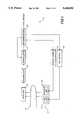
- FIG. 1is a block diagram of a pulse transmittance oximeter
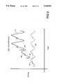
- FIG. 2is a graphical plot as a function of time of the transmittance of light at the red and infrared wavelengths through the finger;
- FIG. 3is a flow chart illustrating the preferred method of the present invention.
- FIG. 4is a graphical plot as a function of time of the transmittance of light at the red wavelength and having a discontinuities as a result of adjusting the intensity of the light output from the red LED;
- FIG. 5is a block diagram of an alternative embodiment of a pulse transmittance oximeter.
- FIG. 6is a flow chart illustrating the preferred method of empirically determining the noise ratio of an oximeter.
- Pulse transmittance oximeter 11comprises a light source 17, a detector 13, a preamplifier 25, a demodulator 27, a microprocessor 29, a red driver 33, and an infrared driver 31.
- the light source 17includes a red LED 21 and an infrared LED 23. Red LED 21 produces red light in the red region of the electromagnetic spectrum. Infrared LED 23 produces infrared light in the infrared region of the electromagnetic spectrum.
- microprocessor 29supplies red control signals to red driver 33 and infrared control signals to infrared driver 31.
- the red control signals and the infrared control signalsare transmitted in alternating sequence such that when a red control signal is being transmitted by microprocessor 29, an infrared control signal is not being transmitted. Similarly, when an infrared control signal is being transmitted by microprocessor 29, a red control signal is not being transmitted.
- microprocessor 29transmits 960 red control signals and 960 infrared control signals in alternating sequence every second. Thus, the pulse transmittance oximeter 11 is said to operate at 960 Hz.
- red driver 33produces a red driving current D R that is transmitted to red LED 21.
- the red driving current D Rcauses red LED 21 to emit a pulse of red light.
- infrared driver 31produces an infrared driving current D IR that is transmitted to infrared LED 23.
- the infrared driving current D IRcauses infrared LED 23 to emit a pulse of infrared light.
- the control signalscause the drivers 31 and 33 to produce driving currents that cause LEDs 21 and 23 to emit a pulse of light.
- both the red and infrared control signalshas integrated therein a magnitude signal that determines the magnitude of the driving currents D R and D IR produced by the drivers 31 and 33.
- the magnitude signalis integrated into each control signals by microprocessor 29.
- the magnitude of the driving currents D R and D IR supplied by drivers 31 and 33 to the LEDsdetermines the intensity of the pulses of light that are output. The larger the driving current supplied to the LEDs, the greater the intensity of the pulses of light produced.
- the LEDs utilizedrespond linearly to the driving current. For example, if the driving current is doubled, the intensity of the light produced by the LED is doubled.
- the microprocessor 29can directly and accurately control the intensity of the pulses of light output by the LEDs by controlling the formulation of the magnitude signal that is integrated to each control signal. Conversely, the intensity of the pulses of light output by the LEDs can be determined at microprocessor 29 by examining the magnitude signal of the control signal that triggered the pulses of light.
- the pulses of red light and the pulses of infrared lightare directed towards and transmitted through tissue having blood flowing therein, such as a finger 15.
- the pulses of red light and the pulses of infrared light that are transmitted through finger 15are received by detector 13 as red transmittance pulses and infrared transmittance pulses, respectively.
- detector 13provides an output signal that is indicative of the intensity of the red transmittance pulses and infrared transmittance pulses incident thereon. Because of the alternating sequence of the pulses of red light and pulses of infrared light, the output signal provided by detector 13 is an alternating sequence of red transmittance pulses and infrared transmittance pulses.
- the output signal produced by detector 13is provided to preamplifier 25 which serves to amplify the output signal.
- the output of preamplifier 25is supplied to demodulator 27 as a demodulator input signal.
- Demodulator 27operates to produce the red and infrared transmission waveforms shown in FIG. 2 from the alternating sequence of red transmittance pulses and infrared transmittance pulses provided by detector 13 via preamplifier 25.
- the red and infrared waveforms of FIG. 2are shown as continuous, the waveforms are comprised of a series of discrete values. Each discrete value corresponds to a single red or infrared transmittance pulse. For clarity however, the discrete values have been connected so as to form the continuous red and infrared waveforms of FIG. 2.
- demodulator 27includes a red sample and hold circuit that responds to the red transmittance pulses produced by detector 13. Further, demodulator 27 also includes an infrared sample and hold circuit that responds to the infrared transmittance pulses produced by detector 13. The timing of the red and infrared sample and hold circuits is controlled by demodulator control signals transmitted by microprocessor 29.
- the demodulator control signalsare generally operative to activate the red sample and hold during the portion of the demodulator input signal that corresponds to the red transmittance pulse.
- the demodulator control signalsare also generally operative to activate the infrared sample and hold during the portion of the demodulator input signal that corresponds to the infrared transmittance pulse. In this manner, the red transmittance pulses and the infrared transmittance pulses are "separated" from one another to provide the red and infrared transmission waveforms of FIG. 2.
- the red and infrared transmission waveformsplotted as a function of time, are cyclical.
- the cyclic nature of the red and infrared transmission waveformsis indicative of the periodic change of blood volume in the tissue of finger 15.
- the changing blood volumeis caused by the beating of the heart of the human being. Specifically, during systolic pressure, the blood volume in the finger 15 is at its highest. Therefore, the transmittance of light is at a low point, corresponding to a low output signal from detector 13. Conversely, during diastolic pressure, the blood volume in the finger is at its lowest. Therefore, the transmittance of light is at a high point, corresponding to a high output signal from detector 13.
- systolic pressure and diastolic pressureoccurs once every heartbeat.
- the cyclic nature of the red and infrared transmission waveformsis due generally to the cyclic heartbeat of the human being.
- each cycle of the transmission waveformscorrespond to one heartbeat.
- the light transmittance at systolic pressure for the red lightis denoted R L
- the light transmittance at diastolic pressure for the red lightis denoted R H
- the light transmittance at systolic pressure for the infrared lightis denoted IR L
- the light transmittance at diastolic pressure for the infrared lightis denoted IR H . Note that in FIG. 2, for clarity, IR L and IR H are shown on a different cyclic period of the waveforms that R L and R H .
- R H and IR Hoccur at substantially the same instant of time, since both R H and IR H are defined to occur during systolic pressure.
- R L and IR Lalso occur at substantially the same instant of time, since both R L and IR L are defined to occur during diastolic pressure.
- the red and infrared transmission waveforms of FIG. 2are provided to microprocessor 29.
- Microprocessor 29formulates the red and infrared control signals that are sent to the drivers 31 and 33.
- the magnitude signal component of the control signalsare based upon the values of R H , R L , IR H , and IR L in the transmission waveforms.
- microprocessor 29(1) normalizes the red and/or infrared transmission waveforms to remove any discontinuities caused by adjusting the intensity of the pulses of light output from red LED 21 or infrared LED 23, (2) filters the red and infrared transmission waveforms, (3) uses peak detection software to determine the values of R H , R L , IR H , and IR L , (4) denormalizes the values of R H , R L , IR H , and IR L , and (5) formulates the magnitude signals in accordance with the method of the present invention, and thus, adjusts the intensity of light output from red LED 21 and infrared LED 23.
- FIG. 3illustrates the operation of microprocessor 29.
- the received red and/or infrared transmission waveformsare normalized to remove any discontinuities in the signal.
- the intensity of the pulses of light output from red LED 21 or infrared LED 23may be varied.
- the intensity of the pulses of light output from the LEDsis dependant upon the magnitude signal component of the red and infrared control signals produced by microprocessor 29.
- the variation of the intensity of the pulses of light output by the red or infrared LEDstend to produce discontinuities in the corresponding red or infrared transmission waveforms.
- the discontinuities caused by the adjustments to the LEDstend to disrupt the operation of the low-pass filtering, at box 45, of the red and infrared transmission waveforms.
- FIG. 4illustrates a red transmission waveform that has two discontinuities.
- an initial waveform 81charts the red transmittance pulses until a first discontinuity 83.
- the first discontinuity 83is caused by a change in the intensity of the pulses of light output by red LED 21.
- the intensity of the pulses of light output by red LED 21is increased.
- subsequent red transmittance pulseswill have a corresponding increased intensity and result in a first increased waveform 89. It has been found that the intensity of the transmittance pulses varies proportionally with the intensity of the pulses of light.
- the intensity of the pulses of light output by the LEDsis increased by seventy-five percent
- the intensity of the transmittance pulsesis increased by seventy-five percent.
- a second discontinuity 85is caused by another change in the intensity of the pulses of light output by red LED 21.
- the intensity of the pulses of light output by red LED 21is increased once again.
- Red transmittance pulses that are subsequent in time to second discontinuity 85will have an increased intensity and result in a second increased waveform 91.
- the step of normalization of box 41scales the first increased waveform 89 and second increased waveform 91 into a normalized waveform 87. Because normalized waveform 87 is substantially continuous with initial waveform 81, the software that implements the low-pass filtering of box 45 will operate correctly. In particular, normalization involves multiplying all of the subsequent discrete values of the red transmittance pulses comprising the first increased waveform 89 that follow the first discontinuity 83 by a red normalization coefficient.
- the red normalization coefficientis the ratio between: (1) the value of the magnitude signal contained in the control signal provided to red driver 33 during the time period of the initial waveform 81 and (2) the value of the magnitude signal contained in the control signal provided to red driver 33 during the time period of the first increased waveform 89.
- the intensity of the pulses of light output by red LED 21is directly controlled by the value of the magnitude signal.
- the intensity of the red transmittance pulsesis proportional to the intensity of the pulses of light output by red LED 21. Therefore, the ratio of the value of the magnitude signals before and after the first discontinuity is representative of the ratio of the red transmittance pulses before and after the first discontinuity.
- the drive current D R output by red driver 33will be doubled, and therefore the intensity of the pulses of red light output by red LED 21 is doubled.
- the intensity of the red transmittance pulses received by detector 13is doubled.
- the red transmittance pulses subsequent to the first discontinuity 83 that form the first increased waveform 89must be multiplied by a red normalizing coefficient of 0.50. This results in the normalized waveform 87 that is substantially continuous with initial waveform 81.
- a similar normalizing procedureoccurs during the second discontinuity 85.
- the second discontinuity 85occurs as a result of an increase in intensity of the pulses of light output by red LED 21.
- a revised red normalization coefficientmust be determined, once again, as the ratio between: (1) the value of the magnitude signal contained in the control signal provided to red driver 33 during the time period of the initial waveform 81 and (2) the value of the magnitude signal contained in the control signal provided to red driver 33 during the time period of the second increased waveform 91. Assuming that the value of the magnitude signal provided by microprocessor 29 during the second increased waveform 91 is three times the value of the magnitude signal during the initial waveform 81, then the red normalization coefficient is 0.33.
- the red normalization coefficientmust be changed.
- the normalization procedurehas been given in the context of a changing intensity of light output from the red LED 21, it can be appreciated that an analogous procedure is done if the intensity of the pulses of light output by infrared LED 23 is varied. Further, if there are no changes to the intensities of the pulses of light output from the LEDs, the normalizing step of box 41 is skipped.
- changes in the intensity of the pulses of light output from the LEDsmay occur in accordance with the method of the present invention.
- movement of the patient's finger 15is one common activity that triggers the method of the present invention to adjust the LED intensity levels.
- the blood volume and thickness of the fingervaries and therefore, the values of R H , R L , IR H , and IR L will vary.
- the LED intensity levelswill vary if the measured values of R H , R L , IR H , and IR L vary.
- the waveformsare processed by a digital low-pass filter implemented as software in the microprocessor.
- the low-pass filtersremove high-frequency noise from the red and infrared transmission waveforms.
- peak detection software within the memory of microprocessor 29operates to determine the values of R H , R L , IR H , and IR L for the next full cycle of the transmission waveforms.
- Various peak detection techniques and the software for implementing the sameare known in the art.
- One such peak detection methodis disclosed in U.S. Pat. No. 4,800,495 to Smith entitled "Method and Apparatus for Processing Signals Used in Oximetry".
- the values of R H , R L , IR H , and IR Lare denormalized to the pre-normalization values prior to the normalization of box 41. This involves multiplying the values of R H , R L , IR H , and IR L by a red denormalization coefficient defined to be the reciprocal of the red and/or infrared normalizing coefficients used in box 41.
- a red denormalization coefficientdefined to be the reciprocal of the red and/or infrared normalizing coefficients used in box 41.
- the red normalization coefficientwas 0.50.
- the red denormalization coefficient for the time period of the first increased waveform 89would be 2.00.
- the red normalization coefficientwas 0.33.
- the red denormalization coefficient for the time period of the second increased waveform 91would be 3.00.
- the step of denormalizationis necessary to reverse the normalization process of box 41, provide a true indication of the output of detector 13, and thus the true values of R H , R L , IR H , and IR L so that further processing in accordance of the present invention may be accomplished. It can be seen that the process of normalization and denormalization is performed primarily to allow the low-pass filtering software to operate upon the red and infrared transmission waveforms.
- the difference between R H and R L and the difference between IR H and IR Lis calculated.
- an adjustment factor Kis calculated.
- the LEDs 21 and 23can emit light at different intensities.
- the LEDsare limited in their operating range. Specifically, the LEDs 21 and 23 have a maximum light output. Thus, driving current D R and D IR to LEDs 21 and 23 must be limited to values that keep the LEDs within operating range.
- the other components of the pulse transmittance oximeter 11may have analogous operating limitations.
- the drivers 31 and 33must produce driving currents only within a predetermined operating range.
- the magnitude signal provided by microprocessor 29could attempt to instruct the driver to produce a large driving current, the driving current dictated by the magnitude signal may be outside the drivers predetermined operating range.
- the detector 13may have an operating range, above and below which, the detector 13 does not operate correctly.
- the operating ranges of the components of oximeter 11limit the operation of the oximeter 11 itself.
- the microprocessor 29must provide control signals that have magnitude signals that dictate a drive current D R and D IR from the drivers 31 and 33 that are within their operating range.
- the drive current D R and D IRmust be within the acceptable range for driving the LEDs 21 and 23.
- the light output by the LEDsmust be of such intensity so as to be within the operating range of detector 13.
- the operation of the oximeter 11 such that all components are within their respective operating rangesis determined by the magnitude signals contained in the control signals.
- the microprocessorBased upon the specific components used for the LEDs 21 and 23, drivers 31 and 33, detector 13, and preamplifier 25, the microprocessor must provide magnitude signals that are within a predetermined range in order for the oximeter 11 as a whole to operate correctly.
- the predetermined rangewill be referred to herein as the magnitude signal range.
- the magnitude signal rangeis the same for both the red and infrared control signals.
- the present inventiondescribed the adjustment of the intensity of the pulses of light output by the LEDs, in the preferred embodiment described here, the adjustments are made by having microprocessor 29 change the magnitude signals. Moreover, the changes in the magnitude signals must be made such that the magnitude signals remain within the magnitude signal range.
- ⁇ R and ⁇ IRare compared to determine if they are substantially equivalent to one another. In the preferred embodiment, ⁇ R and ⁇ IR are considered substantially equivalent if the values are within five percent of one another. If the values of ⁇ R and ⁇ IR are substantially equivalent, at a box 67, R OS in accordance with prior art Eq. (1) is calculated. The calculated value of R OS is then transmitted to a display for use by medical personnel.
- the method of the present inventionoperates to adjust the magnitude signals contained in subsequent red and infrared control signals until the values of ⁇ R and ⁇ IR are substantially equivalent, while maintaining the oximeter 11 within its operating range.
- the value of adjustment factor Kis analyzed. If the value of the adjustment factor K is greater than one, a decision box 59 is executed.
- the magnitude signal contained in the current infrared control signalscan be multiplied by the adjustment factor K and still be within the magnitude signal range, then at a box 61, the magnitude signal contained in subsequent infrared control signals is multiplied by the adjustment factor K. This in turn will cause, via the infrared driver 31, the intensity of the pulses of light output by infrared LED 23 to be multiplied by K.
- a decision box 65is executed.
- the magnitude signal contained in the current red control signalscan be divided by the adjustment factor K and still be within the magnitude signal range, then at box 63, the magnitude signal contained in subsequent red control signals is divided by the adjustment factor K. Note that because the adjustment factor K is less than one, the intensity of the pulses of light output by red LED 21 will actually be increased. If the magnitude signal contained in the current red control signals cannot be divided by the adjustment factor K and still be within the magnitude signal range, then at box 61, the magnitude signal contained in subsequent infrared control signals is multiplied by the adjustment factor K. As noted above, following completion of boxes 61 or 63, R OS in accordance with prior art Eq. (1) is calculated and transmitted for display at box 67.
- the operation of microprocessor 29returns to box 41 to repeat the process of boxes 41-67 for the next cycle of the red and infrared transmission waveforms.
- the intensity of the light output from red LED 21 and infrared LED 23is adjusted such that ⁇ R is substantially equal to ⁇ IR.
- the adjustment factor Konly one adjustment is needed. Further, the adjustment of the LEDs is done in a manner that is non-disruptive to the low-pass filtering.
- condition of Eq. (8)is carried out by microprocessor 29 in performing the iterative routine illustrated in FIG. 3.
- the condition of Eq. (9)is satisfied when:
- Eq. (12)reveals that the calculation of the oxygen saturation ratio is independent of noise.
- Eq. (7)An analysis of Eq. (7) indicates that an alternative embodiment of the present invention exists.
- the result of Eq. (10)is reached when the conditions of Eqs. (8-9) are satisfied.
- the result of Eq. (10)can also be reached when the following condition is met:
- the pulse transmittance oximeterwhen the ratio of ⁇ R and ⁇ IR is equal to the noise ratio R n , the pulse transmittance oximeter is also noise insensitive.
- the noise ratio R nis equivalent to one. This is the case in the preferred embodiment.
- the noise ratio R nis typically not equal to one.
- Pulse transmittance oximeter 111comprises a light source 117, a red detector 113, an infrared detector 114, a red preamplifier 125, an infrared preamplifier 126, a red demodulator 128, an infrared demodulator 127, a microprocessor 129, a red driver 133, and an infrared driver 131.
- the light source 117includes a red LED 123 and an infrared LED 121. Red LED 123 produces red light in the red region of the electromagnetic spectrum. Infrared LED 121 produces infrared light in the infrared region of the electromagnetic spectrum.
- microprocessor 129supplies red control signals to red driver 133 and infrared control signals to infrared driver 131.
- the red control signals and the infrared control signalsare transmitted in alternating sequence.
- red driver 133produces a red driving current D R that causes red LED 123 to emit a pulse of red light.
- infrared driver 131produces an infrared driving current D IR that causes infrared LED 121 to emit a pulse of infrared light.
- the control signalscause the drivers 131 and 133 to produce a driving current that causes the LEDs to emit a pulse of light.
- both the red and infrared control signalshas integrated therein a magnitude signal that determines the magnitude of the driving currents D R and D IR produced by the drivers 131 and 133.
- the magnitude signalis integrated into the control signals by microprocessor 129.
- the magnitude of the driving currents D R and D IR supplied by drivers 131 and 133 to the LEDsdetermines the intensity of the pulses of light that are output. The larger the driving current supplied to the LEDs, the greater the intensity of the pulses of light produced.
- the LEDs utilizedrespond linearly to the driving current. For example, if the driving current is doubled, the intensity of the light produced by the LED is doubled.
- the microprocessor 129can directly and accurately control the intensity of the pulses of light output by the LEDs by controlling the formulation of the magnitude signal. Conversely, the intensity of the pulses of light output by the LEDs can be determined by examining the magnitude signal provided by microprocessor 129.
- the pulses of red light and the pulses of infrared lightare directed towards and transmitted through tissue having blood flowing therein, such as a finger 15.
- the pulses of red light that are transmitted through finger 15are received by red detector 113 as red transmittance pulses.
- the pulses of infrared light that are transmitted through finger 15are received by infrared detector 114 as infrared transmittance pulses.
- red detector 113provides an output signal that is indicative of the intensity of the red transmittance pulses incident thereon and infrared detector 114 provides an output signal that is indicative of the intensity of the infrared transmittance pulses incident thereon.
- the output signal produced by red detector 113is provided to red preamplifier 125 which serves to amplify the red detector output signal.
- the output signal produced by infrared detector 114is provided to infrared preamplifier 126 which serves to amplify the infrared detector output signal.
- the output of red preamplifier 125is supplied to red demodulator 128 as a red demodulator input signal.
- the output of infrared preamplifier 126is supplied to infrared demodulator 127 as an infrared demodulator input signal.
- Red demodulator 128operates to produce red transmission waveforms.
- Infrared demodulator 127operates to produce infrared transmission waveforms. Exemplary of the waveforms that may be produced are those shown in FIG.
- red and infrared waveforms of FIG. 2are shown as continuous, the waveforms are comprised of a series of discrete values. Each discrete value corresponds to a single red or infrared transmittance pulse. For clarity however, the discrete values have been connected so as to form the continuous red and infrared waveforms of FIG. 2.
- the ratio of ⁇ R over ⁇ IRis made equal to the noise ratio R n .
- FIG. 6illustrates one preferred method of determining the noise ratio for oximeter 111.
- oximeter 111is activated as in normal operation described above. However, the red detector 113 and the infrared detector 114 are completely shielded from light.
- noiseis induced into the oximeter 111.
- One method to induce noiseis to lay alongside the oximeter 111 an electrical cable carrying a square wave repeating at one Hertz. The square wave signal tends to induce a wide frequency spectrum of noise into the processing circuitry of the oximeter 111. It has been found that the noise induced in this manner is effective in determining the noise ratio.
- the output of the red demodulator 128is measured at an time t 1 and denoted n r (t 1 ). Similarly, the output of the infrared demodulator 127 is measured at the same time t 1 and denoted n ir (t 1 ). The time t 1 is arbitrary, as long as it is after the oximeter 111 has been activated and is in normal operation.
- the output of the red demodulator 128is measured at an time t 2 and denoted n r (t 2 ). Similarly, the output of the infrared demodulator 127 is measured at the same time t 2 and denoted n ir (t 2 ).
- the time t 2is also arbitrary, as long as it is after time t 1 .
- the noise ratio R nis equal to [n r (t 1 )-n ir (t 1 )]/[n r (t 2 )-n ir (t 2 )]. It has been found that empirical determination of the noise ratio R n in accordance with the above method is a good estimation of the actual noise ratio. After the noise ratio R n has been determined in accordance with FIG. 6, in operation, oximeter 111 continually adjusts the intensity of the pulses of light output by red LED 121 and infrared LED 123 until the ratio of ⁇ R over ⁇ IR is substantially equal to the noise ratio R n .
Landscapes
- Health & Medical Sciences (AREA)
- Life Sciences & Earth Sciences (AREA)
- Engineering & Computer Science (AREA)
- Physics & Mathematics (AREA)
- Surgery (AREA)
- Animal Behavior & Ethology (AREA)
- Pathology (AREA)
- Veterinary Medicine (AREA)
- Biomedical Technology (AREA)
- Heart & Thoracic Surgery (AREA)
- Medical Informatics (AREA)
- Molecular Biology (AREA)
- Public Health (AREA)
- Biophysics (AREA)
- General Health & Medical Sciences (AREA)
- Cardiology (AREA)
- Physiology (AREA)
- Signal Processing (AREA)
- Spectroscopy & Molecular Physics (AREA)
- Optics & Photonics (AREA)
- Artificial Intelligence (AREA)
- Computer Vision & Pattern Recognition (AREA)
- Psychiatry (AREA)
- Measurement Of The Respiration, Hearing Ability, Form, And Blood Characteristics Of Living Organisms (AREA)
Abstract
Description
ΔR=ΔIR (8)
ε.sub.R.sbsb.H -ε.sub.R.sbsb.L =ε.sub.IR.sbsb.H -ε.sub.IR.sbsb.L (9)
ε.sub.R.sbsb.H =ε.sub.IR.sbsb.H
ε.sub.R.sbsb.L =ε.sub.IR.sbsb.L (11)
ΔR/ΔIR=(ε.sub.R.sbsb.H -ε.sub.R.sbsb.L)/(ε.sub.IR.sbsb.H -ε.sub.IR.sbsb.L)(13)
(ε.sub.R.sbsb.H -ε.sub.R.sbsb.L)
(ε.sub.IR.sbsb.H -ε.sub.IR.sbsb.L)
ε.sub.R.sbsb.H =ε.sub.IR.sbsb.H
ε.sub.R.sbsb.L =ε.sub.IR.sbsb.L
Claims (18)
Priority Applications (1)
| Application Number | Priority Date | Filing Date | Title |
|---|---|---|---|
| US07/833,930US5246002A (en) | 1992-02-11 | 1992-02-11 | Noise insensitive pulse transmittance oximeter |
Applications Claiming Priority (1)
| Application Number | Priority Date | Filing Date | Title |
|---|---|---|---|
| US07/833,930US5246002A (en) | 1992-02-11 | 1992-02-11 | Noise insensitive pulse transmittance oximeter |
Publications (1)
| Publication Number | Publication Date |
|---|---|
| US5246002Atrue US5246002A (en) | 1993-09-21 |
Family
ID=25265653
Family Applications (1)
| Application Number | Title | Priority Date | Filing Date |
|---|---|---|---|
| US07/833,930Expired - LifetimeUS5246002A (en) | 1992-02-11 | 1992-02-11 | Noise insensitive pulse transmittance oximeter |
Country Status (1)
| Country | Link |
|---|---|
| US (1) | US5246002A (en) |
Cited By (135)
| Publication number | Priority date | Publication date | Assignee | Title |
|---|---|---|---|---|
| US5411023A (en)* | 1993-11-24 | 1995-05-02 | The Shielding Corporation | Optical sensor system |
| US5494032A (en)* | 1991-07-12 | 1996-02-27 | Sandia Corporation | Oximeter for reliable clinical determination of blood oxygen saturation in a fetus |
| US5503148A (en)* | 1994-11-01 | 1996-04-02 | Ohmeda Inc. | System for pulse oximetry SPO2 determination |
| US5526808A (en)* | 1990-10-04 | 1996-06-18 | Microcor, Inc. | Method and apparatus for noninvasively determining hematocrit |
| US5555882A (en)* | 1992-10-23 | 1996-09-17 | Nellcor Incorporated | Method and apparatus for reducing ambient noise effects in electronic monitoring instruments |
| US5642734A (en)* | 1990-10-04 | 1997-07-01 | Microcor, Inc. | Method and apparatus for noninvasively determining hematocrit |
| WO1997024980A1 (en)* | 1996-01-04 | 1997-07-17 | Circuitry Systems Limited | Bioenergetic data collection apparatus |
| EP0784448A4 (en)* | 1991-03-07 | 1998-01-07 | Masimo Corp | Signal processing apparatus |
| US5776060A (en)* | 1997-02-20 | 1998-07-07 | University Of Alabama In Huntsville | Method and apparatus for measuring blood oxygen saturation within a retinal vessel with light having several selected wavelengths |
| US5800349A (en)* | 1996-10-15 | 1998-09-01 | Nonin Medical, Inc. | Offset pulse oximeter sensor |
| US5935076A (en)* | 1997-02-10 | 1999-08-10 | University Of Alabama In Huntsville | Method and apparatus for accurately measuring the transmittance of blood within a retinal vessel |
| US6115621A (en)* | 1997-07-30 | 2000-09-05 | Nellcor Puritan Bennett Incorporated | Oximetry sensor with offset emitters and detector |
| US6199550B1 (en)* | 1998-08-14 | 2001-03-13 | Bioasyst, L.L.C. | Integrated physiologic sensor system |
| US6263222B1 (en) | 1991-03-07 | 2001-07-17 | Masimo Corporation | Signal processing apparatus |
| US6343223B1 (en)* | 1997-07-30 | 2002-01-29 | Mallinckrodt Inc. | Oximeter sensor with offset emitters and detector and heating device |
| US6501975B2 (en) | 1991-03-07 | 2002-12-31 | Masimo Corporation | Signal processing apparatus and method |
| US6563585B1 (en) | 1999-11-24 | 2003-05-13 | University Of Maryland Biotechnology Institute | Ratiometric fluorometer |
| US6574491B2 (en) | 2000-02-10 | 2003-06-03 | Siemens Medical Systems Inc. | Method and apparatus for detecting a physiological parameter |
| US6650917B2 (en) | 1991-03-07 | 2003-11-18 | Masimo Corporation | Signal processing apparatus |
| US20040126832A1 (en)* | 2002-12-31 | 2004-07-01 | Veutron Corporation | Method for determining the concentration of blood glucose |
| US20040158135A1 (en)* | 1995-08-07 | 2004-08-12 | Nellcor Incorporated, A Delaware Corporation | Pulse oximeter sensor off detector |
| US6889153B2 (en) | 2001-08-09 | 2005-05-03 | Thomas Dietiker | System and method for a self-calibrating non-invasive sensor |
| US6997879B1 (en)* | 2002-07-09 | 2006-02-14 | Pacesetter, Inc. | Methods and devices for reduction of motion-induced noise in optical vascular plethysmography |
| US20060084879A1 (en)* | 2004-10-15 | 2006-04-20 | Pulsetracer Technologies Inc. | Motion cancellation of optical input signals for physiological pulse measurement |
| US20060253150A1 (en)* | 2005-05-05 | 2006-11-09 | Western Clinical Engineering Ltd. | Surgical tourniquet apparatus for measuring limb occlusion pressure |
| US20070014437A1 (en)* | 2004-09-02 | 2007-01-18 | Sony Corporation | Information processing device |
| US20070060813A1 (en)* | 2002-12-11 | 2007-03-15 | Chin-Lien Chang | Establishing a long-term profile of blood sugar level aiding self-control of the same |
| US7194293B2 (en) | 2004-03-08 | 2007-03-20 | Nellcor Puritan Bennett Incorporated | Selection of ensemble averaging weights for a pulse oximeter based on signal quality metrics |
| US20070083336A1 (en)* | 2003-04-04 | 2007-04-12 | Yin-Chun Huang | Method for determining the resolution of blood glucose |
| US20070208225A1 (en)* | 2006-02-23 | 2007-09-06 | Atmos Medizintechnik Gmbh & Co. Kg | Process and arrangement for the production of a signal that corresponds to the opening status of the vocal cords of the larynx |
| EP1905352A1 (en)* | 1994-10-07 | 2008-04-02 | Masimo Corporation | Signal processing apparatus |
| US7376453B1 (en) | 1993-10-06 | 2008-05-20 | Masimo Corporation | Signal processing apparatus |
| US20080139905A1 (en)* | 2003-07-22 | 2008-06-12 | Shoichi Kanayama | Living body information measuring apparatus |
| US20080161663A1 (en)* | 2006-12-29 | 2008-07-03 | Tatung Company | Digital logic module of oximeter sensor probe |
| US20080281174A1 (en)* | 2006-06-16 | 2008-11-13 | Thomas Dietiker | System and method for a non-invasive medical sensor |
| US7471971B2 (en) | 1997-04-14 | 2008-12-30 | Masimo Corporation | Signal processing apparatus and method |
| US7477924B2 (en) | 2006-05-02 | 2009-01-13 | Nellcor Puritan Bennett Llc | Medical sensor and technique for using the same |
| US7483731B2 (en) | 2005-09-30 | 2009-01-27 | Nellcor Puritan Bennett Llc | Medical sensor and technique for using the same |
| US7486979B2 (en) | 2005-09-30 | 2009-02-03 | Nellcor Puritan Bennett Llc | Optically aligned pulse oximetry sensor and technique for using the same |
| US7499740B2 (en) | 2004-02-25 | 2009-03-03 | Nellcor Puritan Bennett Llc | Techniques for detecting heart pulses and reducing power consumption in sensors |
| US7522948B2 (en) | 2006-05-02 | 2009-04-21 | Nellcor Puritan Bennett Llc | Medical sensor and technique for using the same |
| US7555327B2 (en) | 2005-09-30 | 2009-06-30 | Nellcor Puritan Bennett Llc | Folding medical sensor and technique for using the same |
| US7574245B2 (en) | 2006-09-27 | 2009-08-11 | Nellcor Puritan Bennett Llc | Flexible medical sensor enclosure |
| US20090325408A1 (en)* | 2008-06-30 | 2009-12-31 | Marvin Wong | Single Use Connector For Pulse Oximetry Sensors |
| US7647083B2 (en)* | 2005-03-01 | 2010-01-12 | Masimo Laboratories, Inc. | Multiple wavelength sensor equalization |
| US7650177B2 (en) | 2005-09-29 | 2010-01-19 | Nellcor Puritan Bennett Llc | Medical sensor for reducing motion artifacts and technique for using the same |
| US7658652B2 (en) | 2006-09-29 | 2010-02-09 | Nellcor Puritan Bennett Llc | Device and method for reducing crosstalk |
| US7676253B2 (en) | 2005-09-29 | 2010-03-09 | Nellcor Puritan Bennett Llc | Medical sensor and technique for using the same |
| US7680522B2 (en) | 2006-09-29 | 2010-03-16 | Nellcor Puritan Bennett Llc | Method and apparatus for detecting misapplied sensors |
| US7684842B2 (en) | 2006-09-29 | 2010-03-23 | Nellcor Puritan Bennett Llc | System and method for preventing sensor misuse |
| US7689259B2 (en) | 2000-04-17 | 2010-03-30 | Nellcor Puritan Bennett Llc | Pulse oximeter sensor with piece-wise function |
| US20100081901A1 (en)* | 2008-09-30 | 2010-04-01 | Nellcor Puritan Bennett Llc | Medical Sensor And Technique For Using The Same |
| US7738935B1 (en) | 2002-07-09 | 2010-06-15 | Pacesetter, Inc. | Methods and devices for reduction of motion-induced noise in pulse oximetry |
| US7796403B2 (en) | 2006-09-28 | 2010-09-14 | Nellcor Puritan Bennett Llc | Means for mechanical registration and mechanical-electrical coupling of a faraday shield to a photodetector and an electrical circuit |
| US7869849B2 (en) | 2006-09-26 | 2011-01-11 | Nellcor Puritan Bennett Llc | Opaque, electrically nonconductive region on a medical sensor |
| US7880884B2 (en) | 2008-06-30 | 2011-02-01 | Nellcor Puritan Bennett Llc | System and method for coating and shielding electronic sensor components |
| US7881762B2 (en) | 2005-09-30 | 2011-02-01 | Nellcor Puritan Bennett Llc | Clip-style medical sensor and technique for using the same |
| US7890153B2 (en) | 2006-09-28 | 2011-02-15 | Nellcor Puritan Bennett Llc | System and method for mitigating interference in pulse oximetry |
| US7894869B2 (en) | 2007-03-09 | 2011-02-22 | Nellcor Puritan Bennett Llc | Multiple configuration medical sensor and technique for using the same |
| US7899510B2 (en) | 2005-09-29 | 2011-03-01 | Nellcor Puritan Bennett Llc | Medical sensor and technique for using the same |
| US8019400B2 (en) | 1994-10-07 | 2011-09-13 | Masimo Corporation | Signal processing apparatus |
| US8062221B2 (en) | 2005-09-30 | 2011-11-22 | Nellcor Puritan Bennett Llc | Sensor for tissue gas detection and technique for using the same |
| US8068891B2 (en) | 2006-09-29 | 2011-11-29 | Nellcor Puritan Bennett Llc | Symmetric LED array for pulse oximetry |
| US8070508B2 (en) | 2007-12-31 | 2011-12-06 | Nellcor Puritan Bennett Llc | Method and apparatus for aligning and securing a cable strain relief |
| US8071935B2 (en) | 2008-06-30 | 2011-12-06 | Nellcor Puritan Bennett Llc | Optical detector with an overmolded faraday shield |
| US8073518B2 (en) | 2006-05-02 | 2011-12-06 | Nellcor Puritan Bennett Llc | Clip-style medical sensor and technique for using the same |
| US8092379B2 (en) | 2005-09-29 | 2012-01-10 | Nellcor Puritan Bennett Llc | Method and system for determining when to reposition a physiological sensor |
| US8092993B2 (en) | 2007-12-31 | 2012-01-10 | Nellcor Puritan Bennett Llc | Hydrogel thin film for use as a biosensor |
| US8112375B2 (en) | 2008-03-31 | 2012-02-07 | Nellcor Puritan Bennett Llc | Wavelength selection and outlier detection in reduced rank linear models |
| US8133176B2 (en) | 1999-04-14 | 2012-03-13 | Tyco Healthcare Group Lp | Method and circuit for indicating quality and accuracy of physiological measurements |
| US8145288B2 (en) | 2006-08-22 | 2012-03-27 | Nellcor Puritan Bennett Llc | Medical sensor for reducing signal artifacts and technique for using the same |
| US8175671B2 (en) | 2006-09-22 | 2012-05-08 | Nellcor Puritan Bennett Llc | Medical sensor for reducing signal artifacts and technique for using the same |
| US8175667B2 (en) | 2006-09-29 | 2012-05-08 | Nellcor Puritan Bennett Llc | Symmetric LED array for pulse oximetry |
| US8190225B2 (en) | 2006-09-22 | 2012-05-29 | Nellcor Puritan Bennett Llc | Medical sensor for reducing signal artifacts and technique for using the same |
| US20120133936A1 (en)* | 2010-11-30 | 2012-05-31 | Rion Co., Ltd. | Particle counting method |
| US8199007B2 (en) | 2007-12-31 | 2012-06-12 | Nellcor Puritan Bennett Llc | Flex circuit snap track for a biometric sensor |
| US8219170B2 (en) | 2006-09-20 | 2012-07-10 | Nellcor Puritan Bennett Llc | System and method for practicing spectrophotometry using light emitting nanostructure devices |
| US8224412B2 (en) | 2000-04-17 | 2012-07-17 | Nellcor Puritan Bennett Llc | Pulse oximeter sensor with piece-wise function |
| US8221319B2 (en) | 2009-03-25 | 2012-07-17 | Nellcor Puritan Bennett Llc | Medical device for assessing intravascular blood volume and technique for using the same |
| US8233954B2 (en) | 2005-09-30 | 2012-07-31 | Nellcor Puritan Bennett Llc | Mucosal sensor for the assessment of tissue and blood constituents and technique for using the same |
| US8260391B2 (en) | 2005-09-12 | 2012-09-04 | Nellcor Puritan Bennett Llc | Medical sensor for reducing motion artifacts and technique for using the same |
| US8265724B2 (en) | 2007-03-09 | 2012-09-11 | Nellcor Puritan Bennett Llc | Cancellation of light shunting |
| US8280469B2 (en) | 2007-03-09 | 2012-10-02 | Nellcor Puritan Bennett Llc | Method for detection of aberrant tissue spectra |
| US8311601B2 (en) | 2009-06-30 | 2012-11-13 | Nellcor Puritan Bennett Llc | Reflectance and/or transmissive pulse oximeter |
| US8346328B2 (en) | 2007-12-21 | 2013-01-01 | Covidien Lp | Medical sensor and technique for using the same |
| US8352004B2 (en) | 2007-12-21 | 2013-01-08 | Covidien Lp | Medical sensor and technique for using the same |
| US8364220B2 (en) | 2008-09-25 | 2013-01-29 | Covidien Lp | Medical sensor and technique for using the same |
| US8366613B2 (en) | 2007-12-26 | 2013-02-05 | Covidien Lp | LED drive circuit for pulse oximetry and method for using same |
| US8391941B2 (en) | 2009-07-17 | 2013-03-05 | Covidien Lp | System and method for memory switching for multiple configuration medical sensor |
| US8396527B2 (en) | 2006-09-22 | 2013-03-12 | Covidien Lp | Medical sensor for reducing signal artifacts and technique for using the same |
| US20130076911A1 (en)* | 2006-06-01 | 2013-03-28 | Renesas Electronics Corporation | Solid-state imaging apparatus, imaging method, and imaging system |
| US8417309B2 (en) | 2008-09-30 | 2013-04-09 | Covidien Lp | Medical sensor |
| US8417310B2 (en) | 2009-08-10 | 2013-04-09 | Covidien Lp | Digital switching in multi-site sensor |
| US8423112B2 (en) | 2008-09-30 | 2013-04-16 | Covidien Lp | Medical sensor and technique for using the same |
| US8428675B2 (en) | 2009-08-19 | 2013-04-23 | Covidien Lp | Nanofiber adhesives used in medical devices |
| US8433383B2 (en) | 2001-10-12 | 2013-04-30 | Covidien Lp | Stacked adhesive optical sensor |
| US8437822B2 (en) | 2008-03-28 | 2013-05-07 | Covidien Lp | System and method for estimating blood analyte concentration |
| US8442608B2 (en) | 2007-12-28 | 2013-05-14 | Covidien Lp | System and method for estimating physiological parameters by deconvolving artifacts |
| US8452364B2 (en) | 2007-12-28 | 2013-05-28 | Covidien LLP | System and method for attaching a sensor to a patient's skin |
| US8452366B2 (en) | 2009-03-16 | 2013-05-28 | Covidien Lp | Medical monitoring device with flexible circuitry |
| CN103169478A (en)* | 2011-12-26 | 2013-06-26 | 深圳迈瑞生物医疗电子股份有限公司 | Blood oxygen measurement device |
| US8483790B2 (en) | 2002-10-18 | 2013-07-09 | Covidien Lp | Non-adhesive oximeter sensor for sensitive skin |
| US8489364B2 (en) | 2000-06-05 | 2013-07-16 | Masimo Corporation | Variable indication estimator |
| US8505821B2 (en) | 2009-06-30 | 2013-08-13 | Covidien Lp | System and method for providing sensor quality assurance |
| US8509869B2 (en) | 2009-05-15 | 2013-08-13 | Covidien Lp | Method and apparatus for detecting and analyzing variations in a physiologic parameter |
| US20130218027A1 (en)* | 2012-02-22 | 2013-08-22 | Boston Scientific Scimed, Inc. | Imaging device and methods of using the same |
| US8577434B2 (en) | 2007-12-27 | 2013-11-05 | Covidien Lp | Coaxial LED light sources |
| US20130296674A1 (en)* | 2009-09-30 | 2013-11-07 | Nellcor Puritan Bennett Ireland | Systems and methods for normalizing a plethysmograph signal for improved feature analysis |
| US8634891B2 (en) | 2009-05-20 | 2014-01-21 | Covidien Lp | Method and system for self regulation of sensor component contact pressure |
| US8649839B2 (en) | 1996-10-10 | 2014-02-11 | Covidien Lp | Motion compatible sensor for non-invasive optical blood analysis |
| US8781544B2 (en) | 2007-03-27 | 2014-07-15 | Cercacor Laboratories, Inc. | Multiple wavelength optical sensor |
| US8801613B2 (en) | 2009-12-04 | 2014-08-12 | Masimo Corporation | Calibration for multi-stage physiological monitors |
| US20140275878A1 (en)* | 2013-03-15 | 2014-09-18 | Covidien Lp | Methods and systems for equalizing physiological signals |
| US8897850B2 (en) | 2007-12-31 | 2014-11-25 | Covidien Lp | Sensor with integrated living hinge and spring |
| US8965471B2 (en) | 2007-04-21 | 2015-02-24 | Cercacor Laboratories, Inc. | Tissue profile wellness monitor |
| GB2519075A (en)* | 2013-10-08 | 2015-04-15 | Telefield Ltd | Apparatus and method for measuring pulse rate |
| US9010634B2 (en) | 2009-06-30 | 2015-04-21 | Covidien Lp | System and method for linking patient data to a patient and providing sensor quality assurance |
| US9131883B2 (en) | 2002-01-24 | 2015-09-15 | Masimo Corporation | Physiological trend monitor |
| US9161713B2 (en) | 2004-03-04 | 2015-10-20 | Masimo Corporation | Multi-mode patient monitor configured to self-configure for a selected or determined mode of operation |
| CN105380619A (en)* | 2015-11-09 | 2016-03-09 | 深圳诺康医疗设备有限公司 | Method for driving pulse wave detection and method for pulse wave detection |
| AU2015101168B4 (en)* | 2014-09-02 | 2016-06-09 | Apple Inc. | Multiple light paths architecture and obscuration methods for signal and perfusion index optimization |
| WO2016178986A1 (en)* | 2015-05-01 | 2016-11-10 | Lifeq Global Limited | System and method for spo2 determination using reflective ppg |
| US9622693B2 (en) | 2002-12-04 | 2017-04-18 | Masimo Corporation | Systems and methods for determining blood oxygen saturation values using complex number encoding |
| US9675286B2 (en) | 1998-12-30 | 2017-06-13 | Masimo Corporation | Plethysmograph pulse recognition processor |
| US9839381B1 (en) | 2009-11-24 | 2017-12-12 | Cercacor Laboratories, Inc. | Physiological measurement system with automatic wavelength adjustment |
| US9848808B2 (en)* | 2013-07-18 | 2017-12-26 | Cas Medical Systems, Inc. | Method for spectrophotometric blood oxygenation monitoring |
| JP2018029870A (en)* | 2016-08-26 | 2018-03-01 | セイコーエプソン株式会社 | Detection apparatus and detection method |
| JP2019069236A (en)* | 2018-12-28 | 2019-05-09 | 三星電子株式会社Samsung Electronics Co.,Ltd. | Blood pressure measurement device, wristwatch terminal, and blood pressure measurement method |
| US11160473B2 (en)* | 2018-03-23 | 2021-11-02 | Fujifilm Business Innovation Corp. | Biological information measurement device and non-transitory computer readable medium |
| US11350861B2 (en) | 2014-10-10 | 2022-06-07 | Medtor, Inc. | System and method for a non-invasive medical sensor |
| US11998298B2 (en) | 2018-02-26 | 2024-06-04 | Biointellisense, Inc. | System and method for a wearable vital signs monitor |
| US12023153B2 (en) | 2017-02-13 | 2024-07-02 | Apple Inc. | Light restriction designs in optical sensing applications having shared windows |
| US12029586B2 (en) | 2006-10-12 | 2024-07-09 | Masimo Corporation | Oximeter probe off indicator defining probe off space |
| US12064224B2 (en) | 2017-09-26 | 2024-08-20 | Apple Inc. | Concentric architecture for optical sensing |
| US12161447B2 (en) | 2014-08-27 | 2024-12-10 | Apple Inc. | Reflective surfaces for PPG signal detection |
Citations (11)
| Publication number | Priority date | Publication date | Assignee | Title |
|---|---|---|---|---|
| US4407290A (en)* | 1981-04-01 | 1983-10-04 | Biox Technology, Inc. | Blood constituent measuring device and method |
| US4569589A (en)* | 1983-05-25 | 1986-02-11 | University Of Pennsylvania | Lung water computer system |
| US4846183A (en)* | 1987-12-02 | 1989-07-11 | The Boc Group, Inc. | Blood parameter monitoring apparatus and methods |
| US4859057A (en)* | 1987-10-13 | 1989-08-22 | Lawrence Medical Systems, Inc. | Oximeter apparatus |
| US4863265A (en)* | 1987-10-16 | 1989-09-05 | Mine Safety Appliances Company | Apparatus and method for measuring blood constituents |
| US4869254A (en)* | 1988-03-30 | 1989-09-26 | Nellcor Incorporated | Method and apparatus for calculating arterial oxygen saturation |
| US4934372A (en)* | 1985-04-01 | 1990-06-19 | Nellcor Incorporated | Method and apparatus for detecting optical pulses |
| US4942877A (en)* | 1986-09-05 | 1990-07-24 | Minolta Camera Kabushiki Kaisha | Device for measuring oxygen saturation degree in arterial blood |
| US5058588A (en)* | 1989-09-19 | 1991-10-22 | Hewlett-Packard Company | Oximeter and medical sensor therefor |
| US5099123A (en)* | 1989-05-23 | 1992-03-24 | Biosensors Technology, Inc. | Method for determining by absorption of radiations the concentration of substances in absorbing and turbid matrices |
| US5137023A (en)* | 1990-04-19 | 1992-08-11 | Worcester Polytechnic Institute | Method and apparatus for monitoring blood analytes noninvasively by pulsatile photoplethysmography |
- 1992
- 1992-02-11USUS07/833,930patent/US5246002A/ennot_activeExpired - Lifetime
Patent Citations (12)
| Publication number | Priority date | Publication date | Assignee | Title |
|---|---|---|---|---|
| US4407290A (en)* | 1981-04-01 | 1983-10-04 | Biox Technology, Inc. | Blood constituent measuring device and method |
| US4407290B1 (en)* | 1981-04-01 | 1986-10-14 | ||
| US4569589A (en)* | 1983-05-25 | 1986-02-11 | University Of Pennsylvania | Lung water computer system |
| US4934372A (en)* | 1985-04-01 | 1990-06-19 | Nellcor Incorporated | Method and apparatus for detecting optical pulses |
| US4942877A (en)* | 1986-09-05 | 1990-07-24 | Minolta Camera Kabushiki Kaisha | Device for measuring oxygen saturation degree in arterial blood |
| US4859057A (en)* | 1987-10-13 | 1989-08-22 | Lawrence Medical Systems, Inc. | Oximeter apparatus |
| US4863265A (en)* | 1987-10-16 | 1989-09-05 | Mine Safety Appliances Company | Apparatus and method for measuring blood constituents |
| US4846183A (en)* | 1987-12-02 | 1989-07-11 | The Boc Group, Inc. | Blood parameter monitoring apparatus and methods |
| US4869254A (en)* | 1988-03-30 | 1989-09-26 | Nellcor Incorporated | Method and apparatus for calculating arterial oxygen saturation |
| US5099123A (en)* | 1989-05-23 | 1992-03-24 | Biosensors Technology, Inc. | Method for determining by absorption of radiations the concentration of substances in absorbing and turbid matrices |
| US5058588A (en)* | 1989-09-19 | 1991-10-22 | Hewlett-Packard Company | Oximeter and medical sensor therefor |
| US5137023A (en)* | 1990-04-19 | 1992-08-11 | Worcester Polytechnic Institute | Method and apparatus for monitoring blood analytes noninvasively by pulsatile photoplethysmography |
Cited By (287)
| Publication number | Priority date | Publication date | Assignee | Title |
|---|---|---|---|---|
| US5526808A (en)* | 1990-10-04 | 1996-06-18 | Microcor, Inc. | Method and apparatus for noninvasively determining hematocrit |
| US5642734A (en)* | 1990-10-04 | 1997-07-01 | Microcor, Inc. | Method and apparatus for noninvasively determining hematocrit |
| US8948834B2 (en) | 1991-03-07 | 2015-02-03 | Masimo Corporation | Signal processing apparatus |
| US6826419B2 (en) | 1991-03-07 | 2004-11-30 | Masimo Corporation | Signal processing apparatus and method |
| US7215986B2 (en) | 1991-03-07 | 2007-05-08 | Masimo Corporation | Signal processing apparatus |
| US7254433B2 (en) | 1991-03-07 | 2007-08-07 | Masimo Corporation | Signal processing apparatus |
| US8036728B2 (en) | 1991-03-07 | 2011-10-11 | Masimo Corporation | Signal processing apparatus |
| EP0784448A4 (en)* | 1991-03-07 | 1998-01-07 | Masimo Corp | Signal processing apparatus |
| US7383070B2 (en) | 1991-03-07 | 2008-06-03 | Masimo Corporation | Signal processing apparatus |
| US7454240B2 (en) | 1991-03-07 | 2008-11-18 | Masimo Corporation | Signal processing apparatus |
| US8046041B2 (en) | 1991-03-07 | 2011-10-25 | Masimo Corporation | Signal processing apparatus |
| EP2341446A1 (en)* | 1991-03-07 | 2011-07-06 | Masimo Corporation | Signal processing apparatus |
| US6081735A (en)* | 1991-03-07 | 2000-06-27 | Masimo Corporation | Signal processing apparatus |
| US7962190B1 (en) | 1991-03-07 | 2011-06-14 | Masimo Corporation | Signal processing apparatus |
| US6157850A (en)* | 1991-03-07 | 2000-12-05 | Masimo Corporation | Signal processing apparatus |
| US7937130B2 (en) | 1991-03-07 | 2011-05-03 | Masimo Corporation | Signal processing apparatus |
| US7496393B2 (en) | 1991-03-07 | 2009-02-24 | Masimo Corporation | Signal processing apparatus |
| US6236872B1 (en) | 1991-03-07 | 2001-05-22 | Masimo Corporation | Signal processing apparatus |
| US6263222B1 (en) | 1991-03-07 | 2001-07-17 | Masimo Corporation | Signal processing apparatus |
| US7509154B2 (en) | 1991-03-07 | 2009-03-24 | Masimo Corporation | Signal processing apparatus |
| US6501975B2 (en) | 1991-03-07 | 2002-12-31 | Masimo Corporation | Signal processing apparatus and method |
| US8046042B2 (en) | 1991-03-07 | 2011-10-25 | Masimo Corporation | Signal processing apparatus |
| US8942777B2 (en) | 1991-03-07 | 2015-01-27 | Masimo Corporation | Signal processing apparatus |
| US8364226B2 (en) | 1991-03-07 | 2013-01-29 | Masimo Corporation | Signal processing apparatus |
| US7530955B2 (en) | 1991-03-07 | 2009-05-12 | Masimo Corporation | Signal processing apparatus |
| US6650917B2 (en) | 1991-03-07 | 2003-11-18 | Masimo Corporation | Signal processing apparatus |
| USRE38476E1 (en)* | 1991-03-07 | 2004-03-30 | Masimo Corporation | Signal processing apparatus |
| US20040064020A1 (en)* | 1991-03-07 | 2004-04-01 | Diab Mohamed K. | Signal processing apparatus |
| USRE38492E1 (en) | 1991-03-07 | 2004-04-06 | Masimo Corporation | Signal processing apparatus and method |
| US6745060B2 (en) | 1991-03-07 | 2004-06-01 | Masimo Corporation | Signal processing apparatus |
| US5494032A (en)* | 1991-07-12 | 1996-02-27 | Sandia Corporation | Oximeter for reliable clinical determination of blood oxygen saturation in a fetus |
| US5713355A (en)* | 1992-10-23 | 1998-02-03 | Nellcor Puritan Bennett Incorporated | Method and apparatus for reducing ambient noise effects in electronic monitoring instruments |
| US5555882A (en)* | 1992-10-23 | 1996-09-17 | Nellcor Incorporated | Method and apparatus for reducing ambient noise effects in electronic monitoring instruments |
| US8560034B1 (en) | 1993-10-06 | 2013-10-15 | Masimo Corporation | Signal processing apparatus |
| US7328053B1 (en) | 1993-10-06 | 2008-02-05 | Masimo Corporation | Signal processing apparatus |
| US7376453B1 (en) | 1993-10-06 | 2008-05-20 | Masimo Corporation | Signal processing apparatus |
| US5411023A (en)* | 1993-11-24 | 1995-05-02 | The Shielding Corporation | Optical sensor system |
| US8126528B2 (en) | 1994-10-07 | 2012-02-28 | Masimo Corporation | Signal processing apparatus |
| US8755856B2 (en) | 1994-10-07 | 2014-06-17 | Masimo Corporation | Signal processing apparatus |
| US8019400B2 (en) | 1994-10-07 | 2011-09-13 | Masimo Corporation | Signal processing apparatus |
| US8463349B2 (en) | 1994-10-07 | 2013-06-11 | Masimo Corporation | Signal processing apparatus |
| US8359080B2 (en) | 1994-10-07 | 2013-01-22 | Masimo Corporation | Signal processing apparatus |
| EP1905352A1 (en)* | 1994-10-07 | 2008-04-02 | Masimo Corporation | Signal processing apparatus |
| US5503148A (en)* | 1994-11-01 | 1996-04-02 | Ohmeda Inc. | System for pulse oximetry SPO2 determination |
| US20040181134A1 (en)* | 1995-08-07 | 2004-09-16 | Nellcor Puritan Bennett Incorporated | Pulse oximeter with parallel saturation calculation modules |
| US20110071375A1 (en)* | 1995-08-07 | 2011-03-24 | Nellcor Incorporated, A Delaware Corporation | Method and apparatus for estimating physiological parameters using model-based adaptive filtering |
| US7865224B2 (en) | 1995-08-07 | 2011-01-04 | Nellcor Puritan Bennett Llc | Method and apparatus for estimating a physiological parameter |
| US20040158135A1 (en)* | 1995-08-07 | 2004-08-12 | Nellcor Incorporated, A Delaware Corporation | Pulse oximeter sensor off detector |
| US7130671B2 (en) | 1995-08-07 | 2006-10-31 | Nellcor Puritan Bennett Incorporated | Pulse oximeter sensor off detector |
| US20050124871A1 (en)* | 1995-08-07 | 2005-06-09 | Nellcor Puritan Bennett Incorporated | Pulse oximeter with parallel saturation calculation modules |
| US7336983B2 (en) | 1995-08-07 | 2008-02-26 | Nellcor Puritan Bennett Llc | Pulse oximeter with parallel saturation calculation modules |
| US20050085735A1 (en)* | 1995-08-07 | 2005-04-21 | Nellcor Incorporated, A Delaware Corporation | Method and apparatus for estimating a physiological parameter |
| US20060183988A1 (en)* | 1995-08-07 | 2006-08-17 | Baker Clark R Jr | Pulse oximeter with parallel saturation calculation modules |
| US7315753B2 (en) | 1995-08-07 | 2008-01-01 | Nellcor Puritan Bennett Llc | Pulse oximeter with parallel saturation calculation modules |
| US7302284B2 (en) | 1995-08-07 | 2007-11-27 | Nellcor Puritan Bennett Llc | Pulse oximeter with parallel saturation calculation modules |
| US6836679B2 (en) | 1995-08-07 | 2004-12-28 | Nellcor Puritan Bennett Incorporated | Method and apparatus for estimating physiological parameters using model-based adaptive filtering |
| US7931599B2 (en) | 1995-08-07 | 2011-04-26 | Nellcor Puritan Bennett Llc | Method and apparatus for estimating a physiological parameter |
| US20050143634A1 (en)* | 1995-08-07 | 2005-06-30 | Nellcor Incorporated, A Delaware Corporation | Method and apparatus for estimating a physiological parameter |
| US6188470B1 (en) | 1996-01-04 | 2001-02-13 | Larkace Pty Ltd | Bioenergetic data collection apparatus |
| WO1997024980A1 (en)* | 1996-01-04 | 1997-07-17 | Circuitry Systems Limited | Bioenergetic data collection apparatus |
| US8649839B2 (en) | 1996-10-10 | 2014-02-11 | Covidien Lp | Motion compatible sensor for non-invasive optical blood analysis |
| US5800349A (en)* | 1996-10-15 | 1998-09-01 | Nonin Medical, Inc. | Offset pulse oximeter sensor |
| US5935076A (en)* | 1997-02-10 | 1999-08-10 | University Of Alabama In Huntsville | Method and apparatus for accurately measuring the transmittance of blood within a retinal vessel |
| US5776060A (en)* | 1997-02-20 | 1998-07-07 | University Of Alabama In Huntsville | Method and apparatus for measuring blood oxygen saturation within a retinal vessel with light having several selected wavelengths |
| US7471971B2 (en) | 1997-04-14 | 2008-12-30 | Masimo Corporation | Signal processing apparatus and method |
| US7499741B2 (en) | 1997-04-14 | 2009-03-03 | Masimo Corporation | Signal processing apparatus and method |
| US8888708B2 (en) | 1997-04-14 | 2014-11-18 | Masimo Corporation | Signal processing apparatus and method |
| US8190227B2 (en) | 1997-04-14 | 2012-05-29 | Masimo Corporation | Signal processing apparatus and method |
| US8180420B2 (en) | 1997-04-14 | 2012-05-15 | Masimo Corporation | Signal processing apparatus and method |
| US9289167B2 (en) | 1997-04-14 | 2016-03-22 | Masimo Corporation | Signal processing apparatus and method |
| US7489958B2 (en) | 1997-04-14 | 2009-02-10 | Masimo Corporation | Signal processing apparatus and method |
| US6343223B1 (en)* | 1997-07-30 | 2002-01-29 | Mallinckrodt Inc. | Oximeter sensor with offset emitters and detector and heating device |
| US6115621A (en)* | 1997-07-30 | 2000-09-05 | Nellcor Puritan Bennett Incorporated | Oximetry sensor with offset emitters and detector |
| US6199550B1 (en)* | 1998-08-14 | 2001-03-13 | Bioasyst, L.L.C. | Integrated physiologic sensor system |
| US6934571B2 (en) | 1998-08-14 | 2005-08-23 | Bioasyst, L.L.C. | Integrated physiologic sensor system |
| US20030062046A1 (en)* | 1998-08-14 | 2003-04-03 | Wiesmann William Paul | Integrated physiologic sensor system |
| US6606993B1 (en)* | 1998-08-14 | 2003-08-19 | Bioasyst | Integrated physiologic sensor system |
| US9675286B2 (en) | 1998-12-30 | 2017-06-13 | Masimo Corporation | Plethysmograph pulse recognition processor |
| US8133176B2 (en) | 1999-04-14 | 2012-03-13 | Tyco Healthcare Group Lp | Method and circuit for indicating quality and accuracy of physiological measurements |
| US6563585B1 (en) | 1999-11-24 | 2003-05-13 | University Of Maryland Biotechnology Institute | Ratiometric fluorometer |
| US6574491B2 (en) | 2000-02-10 | 2003-06-03 | Siemens Medical Systems Inc. | Method and apparatus for detecting a physiological parameter |
| US7689259B2 (en) | 2000-04-17 | 2010-03-30 | Nellcor Puritan Bennett Llc | Pulse oximeter sensor with piece-wise function |
| US8224412B2 (en) | 2000-04-17 | 2012-07-17 | Nellcor Puritan Bennett Llc | Pulse oximeter sensor with piece-wise function |
| US8078246B2 (en) | 2000-04-17 | 2011-12-13 | Nellcor Puritan Bennett Llc | Pulse oximeter sensor with piece-wise function |
| US8489364B2 (en) | 2000-06-05 | 2013-07-16 | Masimo Corporation | Variable indication estimator |
| US10357206B2 (en) | 2000-06-05 | 2019-07-23 | Masimo Corporation | Variable indication estimator |
| US9138192B2 (en) | 2000-06-05 | 2015-09-22 | Masimo Corporation | Variable indication estimator |
| US7124048B2 (en) | 2000-08-11 | 2006-10-17 | Elekon Industries Usa, Inc. | System and method for a self-calibrating non-invasive sensor |
| US20060122801A1 (en)* | 2000-08-11 | 2006-06-08 | Thomas Dietiker | System and method for a self-calibrating non-invasive sensor |
| US6889153B2 (en) | 2001-08-09 | 2005-05-03 | Thomas Dietiker | System and method for a self-calibrating non-invasive sensor |
| US8433383B2 (en) | 2001-10-12 | 2013-04-30 | Covidien Lp | Stacked adhesive optical sensor |
| US9636056B2 (en) | 2002-01-24 | 2017-05-02 | Masimo Corporation | Physiological trend monitor |
| US9131883B2 (en) | 2002-01-24 | 2015-09-15 | Masimo Corporation | Physiological trend monitor |
| USRE49034E1 (en) | 2002-01-24 | 2022-04-19 | Masimo Corporation | Physiological trend monitor |
| US6997879B1 (en)* | 2002-07-09 | 2006-02-14 | Pacesetter, Inc. | Methods and devices for reduction of motion-induced noise in optical vascular plethysmography |
| US7738935B1 (en) | 2002-07-09 | 2010-06-15 | Pacesetter, Inc. | Methods and devices for reduction of motion-induced noise in pulse oximetry |
| US8483790B2 (en) | 2002-10-18 | 2013-07-09 | Covidien Lp | Non-adhesive oximeter sensor for sensitive skin |
| US9622693B2 (en) | 2002-12-04 | 2017-04-18 | Masimo Corporation | Systems and methods for determining blood oxygen saturation values using complex number encoding |
| US20070060813A1 (en)* | 2002-12-11 | 2007-03-15 | Chin-Lien Chang | Establishing a long-term profile of blood sugar level aiding self-control of the same |
| US20070092923A1 (en)* | 2002-12-11 | 2007-04-26 | Chin-Lien Chang | Establishing a long-term profile of blood sugar level aiding self-control of the same |
| US20040126832A1 (en)* | 2002-12-31 | 2004-07-01 | Veutron Corporation | Method for determining the concentration of blood glucose |
| US7222024B2 (en) | 2002-12-31 | 2007-05-22 | Kuo-Jeng Wang | Method for determining the concentration of blood glucose |
| US20070225583A1 (en)* | 2002-12-31 | 2007-09-27 | Kuo-Jeng Wang | Method for determining the concentration of blood glucose |
| US8478536B2 (en) | 2002-12-31 | 2013-07-02 | Transpacific Systems, Llc | Method for determining the concentration of blood glucose |
| US8320986B2 (en) | 2003-04-04 | 2012-11-27 | Transpacific Systems, Llc | Method for determining the resolution of blood glucose |
| US20070083336A1 (en)* | 2003-04-04 | 2007-04-12 | Yin-Chun Huang | Method for determining the resolution of blood glucose |
| US8600466B2 (en) | 2003-07-22 | 2013-12-03 | Kabushiki Kaisha Toshiba | Living body information measuring apparatus |
| US20080139905A1 (en)* | 2003-07-22 | 2008-06-12 | Shoichi Kanayama | Living body information measuring apparatus |
| EP2371285B1 (en)* | 2003-07-22 | 2017-01-04 | Toshiba Medical Systems Corporation | Living body information measurement device |
| US8886268B2 (en) | 2003-07-22 | 2014-11-11 | Kabushiki Kaisha Toshiba | Living body information measuring apparatus |
| EP1647225A4 (en)* | 2003-07-22 | 2009-04-15 | Toshiba Kk | DEVICE FOR MEASURING BIOLOGICAL INFORMATION |
| US7499740B2 (en) | 2004-02-25 | 2009-03-03 | Nellcor Puritan Bennett Llc | Techniques for detecting heart pulses and reducing power consumption in sensors |
| US9161713B2 (en) | 2004-03-04 | 2015-10-20 | Masimo Corporation | Multi-mode patient monitor configured to self-configure for a selected or determined mode of operation |
| US20070208242A1 (en)* | 2004-03-08 | 2007-09-06 | Nellcor Puritan Bennett Inc. | Selection of ensemble averaging weights for a pulse oximeter based on signal quality metrics |
| US7890154B2 (en) | 2004-03-08 | 2011-02-15 | Nellcor Puritan Bennett Llc | Selection of ensemble averaging weights for a pulse oximeter based on signal quality metrics |
| US8560036B2 (en) | 2004-03-08 | 2013-10-15 | Covidien Lp | Selection of ensemble averaging weights for a pulse oximeter based on signal quality metrics |
| US7194293B2 (en) | 2004-03-08 | 2007-03-20 | Nellcor Puritan Bennett Incorporated | Selection of ensemble averaging weights for a pulse oximeter based on signal quality metrics |
| US7474907B2 (en) | 2004-03-08 | 2009-01-06 | Nellcor Puritan Bennett Inc. | Selection of ensemble averaging weights for a pulse oximeter based on signal quality metrics |
| US20070014437A1 (en)* | 2004-09-02 | 2007-01-18 | Sony Corporation | Information processing device |
| US7634116B2 (en)* | 2004-09-02 | 2009-12-15 | Sony Corporation | Information processing device |
| US20120004519A1 (en)* | 2004-10-15 | 2012-01-05 | Pulse Tracer, Inc. | Motion Cancellation of Optical Input Signals for Physiological Pulse Measurement |
| US20060084879A1 (en)* | 2004-10-15 | 2006-04-20 | Pulsetracer Technologies Inc. | Motion cancellation of optical input signals for physiological pulse measurement |
| US8858454B2 (en)* | 2004-10-15 | 2014-10-14 | Basis Science, Inc. | Motion cancellation of optical input signals for physiological pulse measurement |
| US7993276B2 (en)* | 2004-10-15 | 2011-08-09 | Pulse Tracer, Inc. | Motion cancellation of optical input signals for physiological pulse measurement |
| US7647083B2 (en)* | 2005-03-01 | 2010-01-12 | Masimo Laboratories, Inc. | Multiple wavelength sensor equalization |
| US9131882B2 (en) | 2005-03-01 | 2015-09-15 | Cercacor Laboratories, Inc. | Noninvasive multi-parameter patient monitor |
| US8929964B2 (en) | 2005-03-01 | 2015-01-06 | Cercacor Laboratories, Inc. | Multiple wavelength sensor drivers |
| US9750443B2 (en) | 2005-03-01 | 2017-09-05 | Cercacor Laboratories, Inc. | Multiple wavelength sensor emitters |
| US9351675B2 (en) | 2005-03-01 | 2016-05-31 | Cercacor Laboratories, Inc. | Noninvasive multi-parameter patient monitor |
| US9549696B2 (en) | 2005-03-01 | 2017-01-24 | Cercacor Laboratories, Inc. | Physiological parameter confidence measure |
| US8849365B2 (en) | 2005-03-01 | 2014-09-30 | Cercacor Laboratories, Inc. | Multiple wavelength sensor emitters |
| US8483787B2 (en) | 2005-03-01 | 2013-07-09 | Cercacor Laboratories, Inc. | Multiple wavelength sensor drivers |
| US9241662B2 (en) | 2005-03-01 | 2016-01-26 | Cercacor Laboratories, Inc. | Configurable physiological measurement system |
| US10123726B2 (en) | 2005-03-01 | 2018-11-13 | Cercacor Laboratories, Inc. | Configurable physiological measurement system |
| US8130105B2 (en) | 2005-03-01 | 2012-03-06 | Masimo Laboratories, Inc. | Noninvasive multi-parameter patient monitor |
| US10251585B2 (en) | 2005-03-01 | 2019-04-09 | Cercacor Laboratories, Inc. | Noninvasive multi-parameter patient monitor |
| US8050728B2 (en) | 2005-03-01 | 2011-11-01 | Masimo Laboratories, Inc. | Multiple wavelength sensor drivers |
| US9167995B2 (en) | 2005-03-01 | 2015-10-27 | Cercacor Laboratories, Inc. | Physiological parameter confidence measure |
| US8718735B2 (en) | 2005-03-01 | 2014-05-06 | Cercacor Laboratories, Inc. | Physiological parameter confidence measure |
| US10327683B2 (en) | 2005-03-01 | 2019-06-25 | Cercacor Laboratories, Inc. | Multiple wavelength sensor emitters |
| US8301217B2 (en) | 2005-03-01 | 2012-10-30 | Cercacor Laboratories, Inc. | Multiple wavelength sensor emitters |
| US8190223B2 (en) | 2005-03-01 | 2012-05-29 | Masimo Laboratories, Inc. | Noninvasive multi-parameter patient monitor |
| US10856788B2 (en) | 2005-03-01 | 2020-12-08 | Cercacor Laboratories, Inc. | Noninvasive multi-parameter patient monitor |
| US10984911B2 (en) | 2005-03-01 | 2021-04-20 | Cercacor Laboratories, Inc. | Multiple wavelength sensor emitters |
| US8634889B2 (en) | 2005-03-01 | 2014-01-21 | Cercacor Laboratories, Inc. | Configurable physiological measurement system |
| US8385996B2 (en) | 2005-03-01 | 2013-02-26 | Cercacor Laboratories, Inc. | Multiple wavelength sensor emitters |
| US8626255B2 (en) | 2005-03-01 | 2014-01-07 | Cercacor Laboratories, Inc. | Noninvasive multi-parameter patient monitor |
| US12230393B2 (en) | 2005-03-01 | 2025-02-18 | Willow Laboratories, Inc. | Multiple wavelength sensor emitters |
| US11430572B2 (en) | 2005-03-01 | 2022-08-30 | Cercacor Laboratories, Inc. | Multiple wavelength sensor emitters |
| US8224411B2 (en) | 2005-03-01 | 2012-07-17 | Masimo Laboratories, Inc. | Noninvasive multi-parameter patient monitor |
| US11545263B2 (en) | 2005-03-01 | 2023-01-03 | Cercacor Laboratories, Inc. | Multiple wavelength sensor emitters |
| US12283374B2 (en) | 2005-03-01 | 2025-04-22 | Willow Laboratories, Inc. | Noninvasive multi-parameter patient monitor |
| US8255027B2 (en) | 2005-03-01 | 2012-08-28 | Cercacor Laboratories, Inc. | Multiple wavelength sensor substrate |
| US8912909B2 (en) | 2005-03-01 | 2014-12-16 | Cercacor Laboratories, Inc. | Noninvasive multi-parameter patient monitor |
| US8581732B2 (en) | 2005-03-01 | 2013-11-12 | Carcacor Laboratories, Inc. | Noninvasive multi-parameter patient monitor |
| US7479154B2 (en)* | 2005-05-05 | 2009-01-20 | Mcewen James A | Surgical tourniquet apparatus for measuring limb occlusion pressure |
| US20060253150A1 (en)* | 2005-05-05 | 2006-11-09 | Western Clinical Engineering Ltd. | Surgical tourniquet apparatus for measuring limb occlusion pressure |
| US8260391B2 (en) | 2005-09-12 | 2012-09-04 | Nellcor Puritan Bennett Llc | Medical sensor for reducing motion artifacts and technique for using the same |
| US7899510B2 (en) | 2005-09-29 | 2011-03-01 | Nellcor Puritan Bennett Llc | Medical sensor and technique for using the same |
| US7650177B2 (en) | 2005-09-29 | 2010-01-19 | Nellcor Puritan Bennett Llc | Medical sensor for reducing motion artifacts and technique for using the same |
| US7904130B2 (en) | 2005-09-29 | 2011-03-08 | Nellcor Puritan Bennett Llc | Medical sensor and technique for using the same |
| US8600469B2 (en) | 2005-09-29 | 2013-12-03 | Covidien Lp | Medical sensor and technique for using the same |
| US8060171B2 (en) | 2005-09-29 | 2011-11-15 | Nellcor Puritan Bennett Llc | Medical sensor for reducing motion artifacts and technique for using the same |
| US8965473B2 (en) | 2005-09-29 | 2015-02-24 | Covidien Lp | Medical sensor for reducing motion artifacts and technique for using the same |
| US7676253B2 (en) | 2005-09-29 | 2010-03-09 | Nellcor Puritan Bennett Llc | Medical sensor and technique for using the same |
| US7729736B2 (en) | 2005-09-29 | 2010-06-01 | Nellcor Puritan Bennett Llc | Medical sensor and technique for using the same |
| US7869850B2 (en) | 2005-09-29 | 2011-01-11 | Nellcor Puritan Bennett Llc | Medical sensor for reducing motion artifacts and technique for using the same |
| US8092379B2 (en) | 2005-09-29 | 2012-01-10 | Nellcor Puritan Bennett Llc | Method and system for determining when to reposition a physiological sensor |
| US7555327B2 (en) | 2005-09-30 | 2009-06-30 | Nellcor Puritan Bennett Llc | Folding medical sensor and technique for using the same |
| US8386002B2 (en) | 2005-09-30 | 2013-02-26 | Covidien Lp | Optically aligned pulse oximetry sensor and technique for using the same |
| US7881762B2 (en) | 2005-09-30 | 2011-02-01 | Nellcor Puritan Bennett Llc | Clip-style medical sensor and technique for using the same |
| US7486979B2 (en) | 2005-09-30 | 2009-02-03 | Nellcor Puritan Bennett Llc | Optically aligned pulse oximetry sensor and technique for using the same |
| US8233954B2 (en) | 2005-09-30 | 2012-07-31 | Nellcor Puritan Bennett Llc | Mucosal sensor for the assessment of tissue and blood constituents and technique for using the same |
| US7483731B2 (en) | 2005-09-30 | 2009-01-27 | Nellcor Puritan Bennett Llc | Medical sensor and technique for using the same |
| US8352010B2 (en) | 2005-09-30 | 2013-01-08 | Covidien Lp | Folding medical sensor and technique for using the same |
| US8352009B2 (en) | 2005-09-30 | 2013-01-08 | Covidien Lp | Medical sensor and technique for using the same |
| US8062221B2 (en) | 2005-09-30 | 2011-11-22 | Nellcor Puritan Bennett Llc | Sensor for tissue gas detection and technique for using the same |
| US20070208225A1 (en)* | 2006-02-23 | 2007-09-06 | Atmos Medizintechnik Gmbh & Co. Kg | Process and arrangement for the production of a signal that corresponds to the opening status of the vocal cords of the larynx |
| US8574152B2 (en)* | 2006-02-23 | 2013-11-05 | Atmos Medizintechnik Gmbh & Co. Kg | Process and arrangement for the production of a signal that corresponds to the opening status of the vocal cords of the larynx |
| US8437826B2 (en) | 2006-05-02 | 2013-05-07 | Covidien Lp | Clip-style medical sensor and technique for using the same |
| US8073518B2 (en) | 2006-05-02 | 2011-12-06 | Nellcor Puritan Bennett Llc | Clip-style medical sensor and technique for using the same |
| US7477924B2 (en) | 2006-05-02 | 2009-01-13 | Nellcor Puritan Bennett Llc | Medical sensor and technique for using the same |
| US7522948B2 (en) | 2006-05-02 | 2009-04-21 | Nellcor Puritan Bennett Llc | Medical sensor and technique for using the same |
| US20130076911A1 (en)* | 2006-06-01 | 2013-03-28 | Renesas Electronics Corporation | Solid-state imaging apparatus, imaging method, and imaging system |
| US8780237B2 (en)* | 2006-06-01 | 2014-07-15 | Renesas Electronics Corporation | Solid-state imaging apparatus, imaging method, and imaging system |
| US8271063B2 (en) | 2006-06-16 | 2012-09-18 | Medtor Llc | System and method for a non-invasive medical sensor |
| US20080281174A1 (en)* | 2006-06-16 | 2008-11-13 | Thomas Dietiker | System and method for a non-invasive medical sensor |
| US8577436B2 (en) | 2006-08-22 | 2013-11-05 | Covidien Lp | Medical sensor for reducing signal artifacts and technique for using the same |
| US8145288B2 (en) | 2006-08-22 | 2012-03-27 | Nellcor Puritan Bennett Llc | Medical sensor for reducing signal artifacts and technique for using the same |
| US8219170B2 (en) | 2006-09-20 | 2012-07-10 | Nellcor Puritan Bennett Llc | System and method for practicing spectrophotometry using light emitting nanostructure devices |
| US8190225B2 (en) | 2006-09-22 | 2012-05-29 | Nellcor Puritan Bennett Llc | Medical sensor for reducing signal artifacts and technique for using the same |
| US8396527B2 (en) | 2006-09-22 | 2013-03-12 | Covidien Lp | Medical sensor for reducing signal artifacts and technique for using the same |
| US8195264B2 (en) | 2006-09-22 | 2012-06-05 | Nellcor Puritan Bennett Llc | Medical sensor for reducing signal artifacts and technique for using the same |
| US8190224B2 (en) | 2006-09-22 | 2012-05-29 | Nellcor Puritan Bennett Llc | Medical sensor for reducing signal artifacts and technique for using the same |
| US8175671B2 (en) | 2006-09-22 | 2012-05-08 | Nellcor Puritan Bennett Llc | Medical sensor for reducing signal artifacts and technique for using the same |
| US7869849B2 (en) | 2006-09-26 | 2011-01-11 | Nellcor Puritan Bennett Llc | Opaque, electrically nonconductive region on a medical sensor |
| US8315685B2 (en) | 2006-09-27 | 2012-11-20 | Nellcor Puritan Bennett Llc | Flexible medical sensor enclosure |
| US7574245B2 (en) | 2006-09-27 | 2009-08-11 | Nellcor Puritan Bennett Llc | Flexible medical sensor enclosure |
| US7796403B2 (en) | 2006-09-28 | 2010-09-14 | Nellcor Puritan Bennett Llc | Means for mechanical registration and mechanical-electrical coupling of a faraday shield to a photodetector and an electrical circuit |
| US7890153B2 (en) | 2006-09-28 | 2011-02-15 | Nellcor Puritan Bennett Llc | System and method for mitigating interference in pulse oximetry |
| US8660626B2 (en) | 2006-09-28 | 2014-02-25 | Covidien Lp | System and method for mitigating interference in pulse oximetry |
| US8068891B2 (en) | 2006-09-29 | 2011-11-29 | Nellcor Puritan Bennett Llc | Symmetric LED array for pulse oximetry |
| US7658652B2 (en) | 2006-09-29 | 2010-02-09 | Nellcor Puritan Bennett Llc | Device and method for reducing crosstalk |
| US8175667B2 (en) | 2006-09-29 | 2012-05-08 | Nellcor Puritan Bennett Llc | Symmetric LED array for pulse oximetry |
| US7680522B2 (en) | 2006-09-29 | 2010-03-16 | Nellcor Puritan Bennett Llc | Method and apparatus for detecting misapplied sensors |
| US7684842B2 (en) | 2006-09-29 | 2010-03-23 | Nellcor Puritan Bennett Llc | System and method for preventing sensor misuse |
| US7794266B2 (en) | 2006-09-29 | 2010-09-14 | Nellcor Puritan Bennett Llc | Device and method for reducing crosstalk |
| US12029586B2 (en) | 2006-10-12 | 2024-07-09 | Masimo Corporation | Oximeter probe off indicator defining probe off space |
| US20080161663A1 (en)* | 2006-12-29 | 2008-07-03 | Tatung Company | Digital logic module of oximeter sensor probe |
| US8078248B2 (en)* | 2006-12-29 | 2011-12-13 | Tatung Company | Digital logic module of oximeter sensor probe |
| US8265724B2 (en) | 2007-03-09 | 2012-09-11 | Nellcor Puritan Bennett Llc | Cancellation of light shunting |
| US8280469B2 (en) | 2007-03-09 | 2012-10-02 | Nellcor Puritan Bennett Llc | Method for detection of aberrant tissue spectra |
| US7894869B2 (en) | 2007-03-09 | 2011-02-22 | Nellcor Puritan Bennett Llc | Multiple configuration medical sensor and technique for using the same |
| US8781544B2 (en) | 2007-03-27 | 2014-07-15 | Cercacor Laboratories, Inc. | Multiple wavelength optical sensor |
| US12156733B2 (en) | 2007-04-21 | 2024-12-03 | Masimo Corporation | Tissue profile wellness monitor |
| US10980457B2 (en) | 2007-04-21 | 2021-04-20 | Masimo Corporation | Tissue profile wellness monitor |
| US10251586B2 (en) | 2007-04-21 | 2019-04-09 | Masimo Corporation | Tissue profile wellness monitor |
| US9848807B2 (en) | 2007-04-21 | 2017-12-26 | Masimo Corporation | Tissue profile wellness monitor |
| US8965471B2 (en) | 2007-04-21 | 2015-02-24 | Cercacor Laboratories, Inc. | Tissue profile wellness monitor |
| US11647923B2 (en) | 2007-04-21 | 2023-05-16 | Masimo Corporation | Tissue profile wellness monitor |
| US8352004B2 (en) | 2007-12-21 | 2013-01-08 | Covidien Lp | Medical sensor and technique for using the same |
| US8346328B2 (en) | 2007-12-21 | 2013-01-01 | Covidien Lp | Medical sensor and technique for using the same |
| US8366613B2 (en) | 2007-12-26 | 2013-02-05 | Covidien Lp | LED drive circuit for pulse oximetry and method for using same |
| US8577434B2 (en) | 2007-12-27 | 2013-11-05 | Covidien Lp | Coaxial LED light sources |
| US8452364B2 (en) | 2007-12-28 | 2013-05-28 | Covidien LLP | System and method for attaching a sensor to a patient's skin |
| US8442608B2 (en) | 2007-12-28 | 2013-05-14 | Covidien Lp | System and method for estimating physiological parameters by deconvolving artifacts |
| US8199007B2 (en) | 2007-12-31 | 2012-06-12 | Nellcor Puritan Bennett Llc | Flex circuit snap track for a biometric sensor |
| US8897850B2 (en) | 2007-12-31 | 2014-11-25 | Covidien Lp | Sensor with integrated living hinge and spring |
| US8092993B2 (en) | 2007-12-31 | 2012-01-10 | Nellcor Puritan Bennett Llc | Hydrogel thin film for use as a biosensor |
| US8070508B2 (en) | 2007-12-31 | 2011-12-06 | Nellcor Puritan Bennett Llc | Method and apparatus for aligning and securing a cable strain relief |
| US8437822B2 (en) | 2008-03-28 | 2013-05-07 | Covidien Lp | System and method for estimating blood analyte concentration |
| US8112375B2 (en) | 2008-03-31 | 2012-02-07 | Nellcor Puritan Bennett Llc | Wavelength selection and outlier detection in reduced rank linear models |
| US7887345B2 (en) | 2008-06-30 | 2011-02-15 | Nellcor Puritan Bennett Llc | Single use connector for pulse oximetry sensors |
| US7880884B2 (en) | 2008-06-30 | 2011-02-01 | Nellcor Puritan Bennett Llc | System and method for coating and shielding electronic sensor components |
| US8071935B2 (en) | 2008-06-30 | 2011-12-06 | Nellcor Puritan Bennett Llc | Optical detector with an overmolded faraday shield |
| US20090325408A1 (en)* | 2008-06-30 | 2009-12-31 | Marvin Wong | Single Use Connector For Pulse Oximetry Sensors |
| US8364220B2 (en) | 2008-09-25 | 2013-01-29 | Covidien Lp | Medical sensor and technique for using the same |
| US20100081901A1 (en)* | 2008-09-30 | 2010-04-01 | Nellcor Puritan Bennett Llc | Medical Sensor And Technique For Using The Same |
| US8914088B2 (en)* | 2008-09-30 | 2014-12-16 | Covidien Lp | Medical sensor and technique for using the same |
| US8417309B2 (en) | 2008-09-30 | 2013-04-09 | Covidien Lp | Medical sensor |
| US8423112B2 (en) | 2008-09-30 | 2013-04-16 | Covidien Lp | Medical sensor and technique for using the same |
| US8452366B2 (en) | 2009-03-16 | 2013-05-28 | Covidien Lp | Medical monitoring device with flexible circuitry |
| US8221319B2 (en) | 2009-03-25 | 2012-07-17 | Nellcor Puritan Bennett Llc | Medical device for assessing intravascular blood volume and technique for using the same |
| US8509869B2 (en) | 2009-05-15 | 2013-08-13 | Covidien Lp | Method and apparatus for detecting and analyzing variations in a physiologic parameter |
| US8634891B2 (en) | 2009-05-20 | 2014-01-21 | Covidien Lp | Method and system for self regulation of sensor component contact pressure |
| US8505821B2 (en) | 2009-06-30 | 2013-08-13 | Covidien Lp | System and method for providing sensor quality assurance |
| US8311601B2 (en) | 2009-06-30 | 2012-11-13 | Nellcor Puritan Bennett Llc | Reflectance and/or transmissive pulse oximeter |
| US9010634B2 (en) | 2009-06-30 | 2015-04-21 | Covidien Lp | System and method for linking patient data to a patient and providing sensor quality assurance |
| US8391941B2 (en) | 2009-07-17 | 2013-03-05 | Covidien Lp | System and method for memory switching for multiple configuration medical sensor |
| US8417310B2 (en) | 2009-08-10 | 2013-04-09 | Covidien Lp | Digital switching in multi-site sensor |
| US8428675B2 (en) | 2009-08-19 | 2013-04-23 | Covidien Lp | Nanofiber adhesives used in medical devices |
| US20130296674A1 (en)* | 2009-09-30 | 2013-11-07 | Nellcor Puritan Bennett Ireland | Systems and methods for normalizing a plethysmograph signal for improved feature analysis |
| US11534087B2 (en) | 2009-11-24 | 2022-12-27 | Cercacor Laboratories, Inc. | Physiological measurement system with automatic wavelength adjustment |
| US9839381B1 (en) | 2009-11-24 | 2017-12-12 | Cercacor Laboratories, Inc. | Physiological measurement system with automatic wavelength adjustment |
| US12127833B2 (en) | 2009-11-24 | 2024-10-29 | Willow Laboratories, Inc. | Physiological measurement system with automatic wavelength adjustment |
| US10750983B2 (en) | 2009-11-24 | 2020-08-25 | Cercacor Laboratories, Inc. | Physiological measurement system with automatic wavelength adjustment |
| US12186079B2 (en) | 2009-12-04 | 2025-01-07 | Masimo Corporation | Calibration for multi-stage physiological monitors |
| US8801613B2 (en) | 2009-12-04 | 2014-08-12 | Masimo Corporation | Calibration for multi-stage physiological monitors |
| US11571152B2 (en) | 2009-12-04 | 2023-02-07 | Masimo Corporation | Calibration for multi-stage physiological monitors |
| US10729402B2 (en) | 2009-12-04 | 2020-08-04 | Masimo Corporation | Calibration for multi-stage physiological monitors |
| US20120133936A1 (en)* | 2010-11-30 | 2012-05-31 | Rion Co., Ltd. | Particle counting method |
| US8497989B2 (en)* | 2010-11-30 | 2013-07-30 | Rion Co., Ltd. | Particle counting method |
| CN103169478A (en)* | 2011-12-26 | 2013-06-26 | 深圳迈瑞生物医疗电子股份有限公司 | Blood oxygen measurement device |
| WO2013097599A1 (en)* | 2011-12-26 | 2013-07-04 | 深圳迈瑞生物医疗电子股份有限公司 | Blood oxygen measuring device |
| US20130218027A1 (en)* | 2012-02-22 | 2013-08-22 | Boston Scientific Scimed, Inc. | Imaging device and methods of using the same |
| US20140275878A1 (en)* | 2013-03-15 | 2014-09-18 | Covidien Lp | Methods and systems for equalizing physiological signals |
| US9848808B2 (en)* | 2013-07-18 | 2017-12-26 | Cas Medical Systems, Inc. | Method for spectrophotometric blood oxygenation monitoring |
| US10918321B2 (en) | 2013-07-18 | 2021-02-16 | Edwards Lifesciences Corporation | Method for spectrophotometric blood oxygenation monitoring |
| GB2519075A (en)* | 2013-10-08 | 2015-04-15 | Telefield Ltd | Apparatus and method for measuring pulse rate |
| GB2519075B (en)* | 2013-10-08 | 2017-12-13 | Telefield Ltd | Apparatus and method for measuring pulse rate |
| US12161447B2 (en) | 2014-08-27 | 2024-12-10 | Apple Inc. | Reflective surfaces for PPG signal detection |
| US11536653B2 (en) | 2014-09-02 | 2022-12-27 | Apple Inc. | Multiple light paths architecture and obscuration methods for signal and perfusion index optimization |
| US10215698B2 (en) | 2014-09-02 | 2019-02-26 | Apple Inc. | Multiple light paths architecture and obscuration methods for signal and perfusion index optimization |
| AU2015101168B4 (en)* | 2014-09-02 | 2016-06-09 | Apple Inc. | Multiple light paths architecture and obscuration methods for signal and perfusion index optimization |
| US12072288B2 (en) | 2014-09-02 | 2024-08-27 | Apple Inc. | Multiple light paths architecture and obscuration methods for signal and perfusion index optimization |
| AU2015218442B2 (en)* | 2014-09-02 | 2017-06-29 | Apple Inc. | Multiple light paths architecture and obscuration methods for signal and perfusion index optimization |
| US11350861B2 (en) | 2014-10-10 | 2022-06-07 | Medtor, Inc. | System and method for a non-invasive medical sensor |
| WO2016178986A1 (en)* | 2015-05-01 | 2016-11-10 | Lifeq Global Limited | System and method for spo2 determination using reflective ppg |
| CN105380619B (en)* | 2015-11-09 | 2019-01-04 | 深圳诺康医疗设备股份有限公司 | Method for driving pulse wave to detect and the method for pulse wave detection |
| CN105380619A (en)* | 2015-11-09 | 2016-03-09 | 深圳诺康医疗设备有限公司 | Method for driving pulse wave detection and method for pulse wave detection |
| JP2018029870A (en)* | 2016-08-26 | 2018-03-01 | セイコーエプソン株式会社 | Detection apparatus and detection method |
| US12023153B2 (en) | 2017-02-13 | 2024-07-02 | Apple Inc. | Light restriction designs in optical sensing applications having shared windows |
| US12064224B2 (en) | 2017-09-26 | 2024-08-20 | Apple Inc. | Concentric architecture for optical sensing |
| US12318178B2 (en) | 2017-09-26 | 2025-06-03 | Apple Inc. | Concentric architecture for optical sensing |
| US11998298B2 (en) | 2018-02-26 | 2024-06-04 | Biointellisense, Inc. | System and method for a wearable vital signs monitor |
| US11160473B2 (en)* | 2018-03-23 | 2021-11-02 | Fujifilm Business Innovation Corp. | Biological information measurement device and non-transitory computer readable medium |
| JP2019069236A (en)* | 2018-12-28 | 2019-05-09 | 三星電子株式会社Samsung Electronics Co.,Ltd. | Blood pressure measurement device, wristwatch terminal, and blood pressure measurement method |
Similar Documents
| Publication | Publication Date | Title |
|---|---|---|
| US5246002A (en) | Noise insensitive pulse transmittance oximeter | |
| US4869253A (en) | Method and apparatus for indicating perfusion and oxygen saturation trends in oximetry | |
| US5193543A (en) | Method and apparatus for measuring arterial blood constituents | |
| EP0261788A1 (en) | Multiple-pulse method and apparatus for use in oximetry | |
| EP1286619B1 (en) | Variable mode averager | |
| US4892101A (en) | Method and apparatus for offsetting baseline portion of oximeter signal | |
| EP0261789B1 (en) | Feedback-controlled method and apparatus for processing signals | |
| JP3925945B2 (en) | A method for measuring oxygen saturation in tissues that are supplied with blood without damaging the specimen | |
| US4800495A (en) | Method and apparatus for processing signals used in oximetry | |
| EP0648085B1 (en) | Simulation for pulse oximeter | |
| US4913150A (en) | Method and apparatus for the automatic calibration of signals employed in oximetry | |
| CA2512579C (en) | Selection of preset filter parameters based on signal quality | |
| US5259381A (en) | Apparatus for the automatic calibration of signals employed in oximetry | |
| US6805673B2 (en) | Monitoring mayer wave effects based on a photoplethysmographic signal | |
| JP5193224B2 (en) | Apparatus for continuous noninvasive measurement of arterial pressure and its use | |
| US20110071375A1 (en) | Method and apparatus for estimating physiological parameters using model-based adaptive filtering | |
| EP1006864B1 (en) | Method for harmonically filtering data | |
| HK1003559A1 (en) | Oximeter apparatus and method for measuring arterial blood constituents | |
| WO2009088799A1 (en) | Method and apparatus for assessing contact of a sensor with arterialized tissue | |
| HK1031189B (en) | Method and apparatus for adaptively averaging data signals | |
| HK1031189A1 (en) | Method and apparatus for adaptively averaging data signals | |
| HK1031188B (en) | Method for harmonically filtering data |
Legal Events
| Date | Code | Title | Description |
|---|---|---|---|
| AS | Assignment | Owner name:PHYSIO-CONTROL CORPORATION, WASHINGTON Free format text:ASSIGNMENT OF ASSIGNORS INTEREST.;ASSIGNOR:PROSSER, STEPHEN J.;REEL/FRAME:006013/0335 Effective date:19920206 | |
| STCF | Information on status: patent grant | Free format text:PATENTED CASE | |
| AS | Assignment | Owner name:CREDITANSTALT BANKVEREIN, NEW YORK Free format text:CONDITIONAL ASSIGNMENT;ASSIGNOR:PHYSIO-CONTROL CORPORATION;REEL/FRAME:007118/0001 Effective date:19940729 | |
| REMI | Maintenance fee reminder mailed | ||
| FPAY | Fee payment | Year of fee payment:4 | |
| SULP | Surcharge for late payment | ||
| FEPP | Fee payment procedure | Free format text:PAYOR NUMBER ASSIGNED (ORIGINAL EVENT CODE: ASPN); ENTITY STATUS OF PATENT OWNER: LARGE ENTITY | |
| AS | Assignment | Owner name:NELLCOR PURITAN BENNETT, CALIFORNIA Free format text:ASSIGNMENT OF ASSIGNORS INTEREST;ASSIGNOR:PHYSIO-CONTROL CORPORATION;REEL/FRAME:008943/0109 Effective date:19970822 | |
| FEPP | Fee payment procedure | Free format text:PAYER NUMBER DE-ASSIGNED (ORIGINAL EVENT CODE: RMPN); ENTITY STATUS OF PATENT OWNER: LARGE ENTITY Free format text:PAYOR NUMBER ASSIGNED (ORIGINAL EVENT CODE: ASPN); ENTITY STATUS OF PATENT OWNER: LARGE ENTITY | |
| FPAY | Fee payment | Year of fee payment:8 | |
| FPAY | Fee payment | Year of fee payment:12 |