US5245869A - High accuracy mass sensor for monitoring fluid quantity in storage tanks - Google Patents
High accuracy mass sensor for monitoring fluid quantity in storage tanksDownload PDFInfo
- Publication number
- US5245869A US5245869AUS07/769,865US76986591AUS5245869AUS 5245869 AUS5245869 AUS 5245869AUS 76986591 AUS76986591 AUS 76986591AUS 5245869 AUS5245869 AUS 5245869A
- Authority
- US
- United States
- Prior art keywords
- fluid
- sensor
- signal
- displacement
- bellows
- Prior art date
- Legal status (The legal status is an assumption and is not a legal conclusion. Google has not performed a legal analysis and makes no representation as to the accuracy of the status listed.)
- Expired - Fee Related
Links
Images


Classifications
- G—PHYSICS
- G01—MEASURING; TESTING
- G01M—TESTING STATIC OR DYNAMIC BALANCE OF MACHINES OR STRUCTURES; TESTING OF STRUCTURES OR APPARATUS, NOT OTHERWISE PROVIDED FOR
- G01M3/00—Investigating fluid-tightness of structures
- G01M3/02—Investigating fluid-tightness of structures by using fluid or vacuum
- G01M3/26—Investigating fluid-tightness of structures by using fluid or vacuum by measuring rate of loss or gain of fluid, e.g. by pressure-responsive devices, by flow detectors
- G01M3/32—Investigating fluid-tightness of structures by using fluid or vacuum by measuring rate of loss or gain of fluid, e.g. by pressure-responsive devices, by flow detectors for containers, e.g. radiators
- G01M3/3236—Investigating fluid-tightness of structures by using fluid or vacuum by measuring rate of loss or gain of fluid, e.g. by pressure-responsive devices, by flow detectors for containers, e.g. radiators by monitoring the interior space of the containers
- G01M3/3245—Investigating fluid-tightness of structures by using fluid or vacuum by measuring rate of loss or gain of fluid, e.g. by pressure-responsive devices, by flow detectors for containers, e.g. radiators by monitoring the interior space of the containers using a level monitoring device
- G—PHYSICS
- G01—MEASURING; TESTING
- G01F—MEASURING VOLUME, VOLUME FLOW, MASS FLOW OR LIQUID LEVEL; METERING BY VOLUME
- G01F23/00—Indicating or measuring liquid level or level of fluent solid material, e.g. indicating in terms of volume or indicating by means of an alarm
- G01F23/14—Indicating or measuring liquid level or level of fluent solid material, e.g. indicating in terms of volume or indicating by means of an alarm by measurement of pressure
- G01F23/16—Indicating, recording, or alarm devices being actuated by mechanical or fluid means, e.g. using gas, mercury, or a diaphragm as transmitting element, or by a column of liquid
- G01F23/164—Indicating, recording, or alarm devices being actuated by mechanical or fluid means, e.g. using gas, mercury, or a diaphragm as transmitting element, or by a column of liquid using a diaphragm, bellow as transmitting element
- G—PHYSICS
- G01—MEASURING; TESTING
- G01F—MEASURING VOLUME, VOLUME FLOW, MASS FLOW OR LIQUID LEVEL; METERING BY VOLUME
- G01F23/00—Indicating or measuring liquid level or level of fluent solid material, e.g. indicating in terms of volume or indicating by means of an alarm
- G01F23/14—Indicating or measuring liquid level or level of fluent solid material, e.g. indicating in terms of volume or indicating by means of an alarm by measurement of pressure
- G01F23/18—Indicating, recording or alarm devices actuated electrically
Definitions
- the present inventionrelates to method and apparatus for monitoring fluid quantity in storage tanks.
- Inventory control and leak monitoring of stored fluidswhich may be highly flammable, corrosive, or reactive, requires an accurate sensor that can withstand this environment and yet can provide exceptional stability with high sensitivity.
- an accurate sensorthat may be used in a storage tank containing hydrocarbon fluids (gasoline, diesel fuels, aviation fuels, etc.) capable of monitoring both the quantity of such fluid present in the tank for inventory control (to an accuracy of 1/8' or better) and the loss of such fluid over time for leak detection (for rates as low as 0.05 or at least 0.1 gal/hour).
- the quantity of hydrocarbon fluid in a storage tankis reported as either a gross volume at ambient temperature or as normalized to a net volume at 60° F., and presently there is a need for a cost-effective sensor system which can accurately provide such gross and net data in such environment, and at a resolution which enables loss detection at 0.1 gal/hour.
- the significant thermal expansion coefficient of hydrocarbon fluidsrequires that sensing methods insensitive to temperature-induced volume changes be used to successfully detect the loss of such fluids with a low probability of false leak detection.
- Conventional systemsemploy various level sensing and volumetric methods, and attempt to correct errors caused by thermal expansion of the fluid by monitoring temperature throughout the tank.
- an object of the Present inventionto provide a high resolution and highly accurate sensor and system for monitoring the amount of hydrocarbon fluid in a storage tank.
- the present applicationdescribes a system for monitoring the amount of fluid in a storage tank with an accuracy high enough to determine both the quantity present and the potential loss of fluid at a loss rate of 0.05 gal/h or at least 0.1 gal/hr.
- the systemutilizes a detection device positioned at the bottom of the tank and in contact with the fluid.
- This deviceincludes a bellows unit whose displacement is correlated to changes in the mass of fluid in which it is immersed, and a transducer for monitoring the position of the bellows.
- the transducer outputprovides a relatively low resolution measurement of fluid quantity for inventory control purposes, while this same output also can be optimized for highly accurate leak detection.
- the systemdetermines the quantity of fluid in the tank by measuring the mass of fluid above a pressure sensor.
- the sensorincludes a multiple-capsule bellows unit which is quite sensitive and whose movement accurately reflects the mass load or changes therein of the fluid in the tank.
- An electro-mechanical transducermonitors the surface of the bellows unit while remaining out of contact with the fluid bulk, so as to eliminate fouling or interference from any reactivity or corrosivity of the fluids.
- the deviceSince the device is mass-sensitive (i.e., measures the weight of the column), rather than level-sensing or volume-measuring, it is essentially immune to temperature effects (except for thermal expansion of the device itself) when measuring the contents of a vertically-walled tank.
- the present inventionrecognizes that measuring the height of a fluid directly is subject to error from thermal effects, and requires temperature compensation, while in a purely pressure measurement, thermal compensation is not required
- a storage tank with vertical walls perpendicular to the force of gravitythe conventional above-ground fuel storage tank
- sensing the pressure exerted by this unchanging mass at the bottom of such storage tankcan produce reliable quantitative results, without the need for temperature compensation.
- a pressure sensoris placed at the bottom of a vertically-walled storage tank to determine the mass of the stored fluid. Compensation for thermal expansion of the stored fluid is not required for gross measurement at ambient temperature, except for compensation for thermal effects upon the sensor itself.
- gross datacan be normalized to net quantity at 60° F.
- temperature datacan be processed to obtain loss rate for leak detection, and in a particular embodiment, can achieve resolution of better than 0.05 gal/hr.
- such temperature datais used to correct for the effects of having a non-vertically walled container, such as present in most underground storage tanks. Even so, in practice of the invention, less temperature correction is required and less expensive temperature sensors can be used compared to conventional devices obtaining the same accuracy.
- a linear variable differential transformerconnected to a specially designed multiple-capsule bellows assembly detects differential pressure directly related to the measured column of fluid.
- the bellows unitis vented to the vapor pressure at the top of the fluid within the tank, which makes the system functional in both vented and unvented tanks, and virtually insensitive to atmospheric pressure influence.
- two separate temperature correctionsare made.
- Oneis for fluid expansion, and the other is for the errors induced by temperature changes in the sensor device itself.
- the formeris performed by disclosed signal processing techniques.
- the latteris performed by disclosed signal processing techniques based upon data obtained from the LVDT, and a temperature sensor adjacent to the LVDT for correction of thermal drift in that component, and by a disclosed selection, construction and combination of materials having low and self-compensating thermal expansion effects.
- the column pressure P exerted on the exterior of the bellows unitis given as the density of the fluid ⁇ multiplied by the height h of the column plus atmospheric pressure P 0 at the top of the column.
- P 0is canceled by taking the surface pressure at the top of the fluid within the tank and presenting that to the interior of the bellows unit.
- the sensor systemis independent of exogenous factors related to external static or atmospheric pressure, humidity, or the like, and the sensed column pressure P can be divided by the known density ⁇ to obtain the height of the column (which is then converted to gallons).
- FIG. 1is a schematic diagram of a sensor system according to the invention
- FIG. 2is a side cross-sectional view of a sensor of the invention in a column of fluid
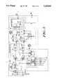
- FIG. 3is a block diagram of the electronic signal conditioning and process package of the invention.
- FIG. 4is a flow chart of the inventory control process of the invention.
- FIG. 5is a flow chart of the leak detection process of the invention.
- a mass sensor system 10 of the inventionis shown in FIG. 1 including a sensor assembly 12 located at or near the bottom 14 of a closed storage tank 16 which contains hydrocarbon fluid 18.
- System 10detects the mass, and changes in the mass, of fluid 18, as changes in pressure and correlates this pressure data to fluid quantity for inventory) and loss rate (for leak detection).
- Sensor assembly 12generates a detection signal representative of the difference between the pressure of two atmospheres, i.e., of the fluid vapor (A1) and of the tank bottom (A2), enclosed within the tank. This signal is transmitted on cable 20 to an energizing, conditioning and processing electronics package 24.
- Package 24is coupled via cable 22 to a power supply and displaying computer 26, and provides two sets of data to computer 26: fluid volume and change in fluid volume.
- vertically walled tank 16extends up to a terminating neck 28 having a flanged opening 30 which is closed by means of cover plate 32 and is sealed thereat forming a vapor seal 34 between the flanged opening and cover plate.
- Cover plate 32defines a passage 38 through which extends cable 20 to carry the detection signal from sensor assembly 12 within the sealed tank to the external electronics package 24.
- Cable 20is safety sealed at its outer diameter where it passes through plate 32 by means of a potting compound, such as Scotchcast No. 4403 available from 3M Corporation.
- Cables 20 and 22connect to electronics package 24 and computer 26 by means of electrical safety barriers B1, B2 and B3. Barriers B1 and B2 are also sealed with potting compound.
- electronics package 24is housed in an explosion proof box.
- sensing section 46The exterior of a sensing section 46 at the base of sensor assembly 12 is in fluid communication with atmosphere A2 of the stored fluid 18.
- a vent tube 40is mounted to the bottom of cover plate 32, and opens out thereat at vent 42 (or perhaps by means of a sealed pressure transfer membrane to prevent fluid entry into the tube) in communication with the fluid vapor atmosphere A1 in the tank.
- the interior of sensing section 46 and a transducer section 48 of sensor assembly 12are coupled by vent tube 40 to, and pressurized according to, the fluid vapor atmosphere A1.
- Sensing section 46senses the difference between the pressure of the two atmospheres A1, A2 within the tank and is mechanically displaced according to such difference.
- Transducer 48senses such mechanical displacement and converts it to an electrical detection signal output representative thereof, which is then conditioned and processed by package 24 in a manner described later.
- sensor 12is shown located at the bottom 14 of a tank and immersed in the hydrocarbon fluid 18 in atmosphere A2.
- Sensor element 46includes a multi-stage bellows assembly 50 within a protective housing 52.
- the housinghas passages 54 for free admission of fluid 18 into and surrounding the exterior of capsules 56 of the bellows assembly, and therefore are submitted to the fluid atmosphere A2 at the bottom of the tank.
- the transducer section 48is at atmosphere A1 supplied via vent tube 40, and is sealed from the fluid atmosphere A2.
- the transducer sectionincludes a base plate 66, side support 72 and top plate 74 all sealed to each other. Housing 72 top plate 74 has passages 76, 78 for receipt of vent tube 40 and cable 20, as sealed by potting compound, respectively.
- the bellows assembly 50is mounted on a flange plate 68 which is sealingly engaged by means of 0-ring 70 at the bottom of base plate 66.
- a hollow support structure 60supports the bellows assembly 50 and extends down from flange plate 68, and the interior of structure 60 is in atmospheric communication with the interior of transducer section 48 via corresponding openings in plates 66, 68, respectively, and with the interiors of capsules 56, at the pressure of atmosphere A1, and seal 62 isolates this from the fluid environment (A2).
- Capsules 56are serially coupled by means of shaft 58 to which they are mounted, the shaft extending within chambered support 60 and into transducer section 48 through plates 66, 68.
- Transducer section 48includes an electrical pickup transducer 88, having a central annulus 64 through which extends a core 90 mounted at the end of a coupler 59 on shaft 58, and therefore the displacement of shaft 58 causes displacement of core 90 within transducer 88, for generating a detection signal reflective of displacement of the pressure-sensitive capsules.
- Bellows assembly 50preferably comprises three thin, disk-shaped capsules 56, each of which are held extended by an internal spring action and which expand and contract with changes in the pressure difference between atmospheres A1 and A2.
- the capsulesare fabricated from NiSpanC and the support 60, spacers 61, and plates 66, 68 are made of INVAR, for minimal and known thermal expansion.
- Plunger 58 and coupler 59are also made of INVAR. These components are then selected so that the amount of thermal expansion of the transducer 88, plates 66, 68, support 60, spacers 61 and capsules 56 is equal to the amount of thermal expansion of plunger 58, coupler 59 and core 90.
- capsules 56are each partially evacuated and sealed, in the present invention the capsules are internally coupled so that they all are submitted to the same internal atmosphere A1 on the same side of the bellows assembly as its attachment to plate 68.
- Such mounting and attachmentfacilitates the thermal balancing just described, and the comparison of the selected atmospheres (A1 and A2) eliminates exogenous errors.
- transducer 88is an AC operated LVDT.
- the LVDTis a mutual inductance element. It produces an electrical output proportional to the displacement of core 90.
- the transformerincludes a primary coil winding 92 and two identical secondaries 94, 96, symmetrically spaced from the primary. The secondaries are connected externally in series opposition in a synchronous demodulation circuit within package 24 for retrieving phase information from the detector indicative of bellows displacement and correlated to differentiated pressure, which in turn is correlated with volume.
- each secondaryAs core 90 is displaced the mutual inductance of each secondary is varied relative to the primary, which determines the voltage induced from the primary to each secondary.
- Coils 92, 94, 96are accordingly appropriately coupled to driver electronics in package 24. Because there is no physical contact between the core and the coil, mechanical components of the LVDT do not wear out or deteriorate, and this renders the LVDT a reliable device for use in a hazardous environment.
- the corresponding absence of frictiongives essentially infinite resolution and little or no hysteresis.
- the small core mass and the lack of frictionenhance response capabilities for dynamic measurements.
- the transducer and bellows assemblymay be assembled and calibrated at the factory.
- an outputis derived from the sensor installed in the empty tank, indicative of zero fluid volume, and then the tank is filled to its maximum and the corresponding displacement of capsules 56 displaces core 90, accordingly inducing a differential output representative of such filled volume.
- the system calibrationmay include input from a tank environment controller or may proceed in an unaided self-calibration mode. The latter mode is implemented by monitoring addition or removal of known amounts of fluid from the tank, such as by means of one or more fixed-location height-measurement devices (e.g., optical devices H 1 , H 2 ), which provide a known fluid height, and from which height information, ⁇ and ⁇ may be derived.
- the rate of change of the detection signal, or signalsprovides fluid loss rate.
- sensor barrier circuit 100applies an excitation voltage from sine drive circuit 102 to the LVDT primary coil 92, and a differential pressure signal representative of displacement of core 90 (driven by changes in the bellows assembly 50 and plunger 58) and derived from the two secondaries 94, 96 is inputted to sensor barrier circuit 100, all via cable 20. Also inputted to barrier 100 via cable 20 is temperature data from sensor T 0 (which is mounted at transducer 88). In a preferred embodiment, the system is further provided with temperature data from sensors T l to T n (mounted at various strata within the tank), for more accurate temperature correction.
- the barrier circuitis an intrinsically safe protection circuit that eliminates any possibility of causing an ignition situation in the hostile environment.
- the barrier circuit output V 1is split between a low-gain inventory signal demodulator channel (I), including post-amp 106, synchronous demodulator/low pass filter 108 and DC amplifier 110, and a high-gain leak detection demodulator channel (II), including post-amp 112, synchronous demodulator/low pass filter 114 and DC amplifier 116, and offset adjust circuit 118.
- the output of each channelis an LVDT displacement-versus-output voltage, having a sensitivity of 0.036 inches/volt or 240 microinches/volt for inventory or leak detection, respectively.
- the outputs of the inventory and leak channelsare applied via interfacing amplifier circuits 120 to the A/D inputs of microprocessor 122.
- the microprocessoroutputs a feedback signal V f to the offset adjust circuit 118 which ranges the higher-sensitivity output of the leak channel (II) to a useable level before application to amplifiers 120.
- the inventory channelhas a slow integration-type response while the leak channel has a fast response. The latter is used to make a decision as to whether the offset level must be updated.
- the pressure signal outputted by either channel I or IIcan be processed by the microcomputer 122 to determine the inventory quantity or loss rate.
- the densitymust be adjusted for thermal effects. Therefore thermal data from inputs T 0 to T n via networks 124, 126 and multiplexer 128 is applied via interface 120 to the microcomputer. It is noted that the temperature data T 0 enables compensation for thermal effects directly at the sensor 12, while thermal data from inputs T l to T n enables independent compensation for thermal gradients within the tank.
- the sensor signal representing the bellows displacementis compensated for the transducer (LVDT) non-linearity, for the effect of its installation at but slightly above the actual bottom of the tank and for temperature drift, to obtain an adjusted displacement value.
- This valueis adjusted for the non-linearity and spring constant of the bellows to obtain a pressure value.
- the latteris then adjusted for the density of the measured fluid (and the density itself is adjusted for the temperature of the fluid, for gravity effects, and for the thermal expansion coefficient of the fluid), to obtain a column height value, and this is converted in a strapping table (a cross-reference between vertical height of the fluid and volume according to characteristics of the tank in which the system is installed) into gross quantity in gallons at current temperature.
- the column height valuecan also be normalized to the industry standard of 60° F. by use of an appropriate density value, in which event an adjusted column height value will be applied to the strapping table and the output will be in net gallons. Alternatively, the gross volume may be corrected by using the same normalization factors to directly yield net gallons, in which event use of the strapping table would be minimized.
- the final readoutis preferably based upon several iterations, such as where temperature data for strata of the fluid is available.
- the inventory signal processing routine employed by the microprocessoris shown in FIG. 4, where the displacement signal D from the LVDT, adjusted for the LVDT transfer function H, and the temperature data f T , adjusted for the LVDT temperature function f(T), produce the product D 0 as a distance datum (which represents the displacement of the bellows), and, adjusted for the bellows transfer function K t , obtains a pressure value P T , which in turn is adjusted by a determined density value ⁇ T , determined by the function ⁇ (T), to obtain the height h of the measured fluid.
- This valueis converted by a strapping table to obtain gallons as a function f h of height (which reflects the particular geometric volume dependency on the height of the fluid in the tank) to obtain an output representative of the gallons G in the tank. This output is applied to computer 26 for display of the volume of fluid in the tank.
- the sensor signal representing the bellows displacementis autoranged at expanded gain to an operative level and is compensated for transducer non-linearity, for the effect of its installation at but slightly above the actual bottom of the tank, and for temperature drift, to obtain a modified adjusted displacement value.
- This valueis then adjusted for the non-linearity and spring constant of the bellows to obtain a modified pressure value.
- the latteris then adjusted for the net density of the measured fluid to obtain a modified column height value, and this is converted in a strapping table to quantity in gallons.
- a sequence of these readingsis taken over a period of time, or at least one other reading is taken after a period of time, to determine leak rate in gallons per hour.
- the leak detection scheme employed by the microprocessoris shown in FIG. 5, where the offset data signal D' from the LVDT, adjusted for the LVDT transfer function H', and the temperature data f T , adjusted for the LVDT temperature function f(T), produce the product D 0 ' as a distance datum (which represents the displacement of the bellows with greater accuracy), and, adjusted for the bellows transfer function K t , obtains pressure value P T , which in turn is adjusted by a determined density value ⁇ T ', derived from ⁇ T adjusted for by K A (which is a high sensitivity correction necessary for the fluid density as a function of temperature), to obtain the height h of the measured fluid.
- This valueis again converted to obtain an output representative of the gallons G in the tank. This output is then compared to a series of like readings over a period, or to a second reading at the end of a period, to obtain a loss rate in gallons per hour, which is used at computer 26 accordingly.
- the ⁇ T and ⁇ T ' functionsalso are corrected for deviation in the local acceleration of gravity g, thermistor inputs T l -T n , the thermal coefficient of expansion for the stored fluid ⁇ , and the density of the fluid at 60° F. ⁇ 0 , and also possibly for T 0 if used as part of the strata temperature data.
- the leak measurement systemis quite sensitive, and therefore such measurements should not be made within an hour after the fluid has been pumped, battered or moved.
- the low pass filtersmay be replaced by digital signal processing within the microprocessor, so as to overcome excessively noisy environments in which vehicle passage, filling and dispensing turbulence or other disturbances must be canceled.
Landscapes
- Physics & Mathematics (AREA)
- General Physics & Mathematics (AREA)
- Fluid Mechanics (AREA)
- Examining Or Testing Airtightness (AREA)
- Measuring Fluid Pressure (AREA)
Abstract
Description
P=ρ×h+P.sub.0,
Claims (16)
Priority Applications (1)
| Application Number | Priority Date | Filing Date | Title |
|---|---|---|---|
| US07/769,865US5245869A (en) | 1991-10-01 | 1991-10-01 | High accuracy mass sensor for monitoring fluid quantity in storage tanks |
Applications Claiming Priority (1)
| Application Number | Priority Date | Filing Date | Title |
|---|---|---|---|
| US07/769,865US5245869A (en) | 1991-10-01 | 1991-10-01 | High accuracy mass sensor for monitoring fluid quantity in storage tanks |
Publications (1)
| Publication Number | Publication Date |
|---|---|
| US5245869Atrue US5245869A (en) | 1993-09-21 |
Family
ID=25086746
Family Applications (1)
| Application Number | Title | Priority Date | Filing Date |
|---|---|---|---|
| US07/769,865Expired - Fee RelatedUS5245869A (en) | 1991-10-01 | 1991-10-01 | High accuracy mass sensor for monitoring fluid quantity in storage tanks |
Country Status (1)
| Country | Link |
|---|---|
| US (1) | US5245869A (en) |
Cited By (40)
| Publication number | Priority date | Publication date | Assignee | Title |
|---|---|---|---|---|
| US5423457A (en)* | 1993-04-30 | 1995-06-13 | Suntronic Technology Group, Inc. | Real time tank product loss detection system |
| US5565076A (en)* | 1995-05-22 | 1996-10-15 | Henkel Corporation | Fluoride sensing electrodes with longer service life, retrofittable shields therefor, and processes utilizing such electrodes |
| US5641006A (en)* | 1995-07-13 | 1997-06-24 | Chiron Diagnostics Corporation | Liquid supply apparatus and method of operation |
| US5686658A (en)* | 1995-10-05 | 1997-11-11 | Asttest Services, Inc. | Aboveground liquid storage tank leakage detection |
| US5693881A (en)* | 1994-12-15 | 1997-12-02 | Sitachitt; Sidney | Sensor-based liquid leveling system for structures |
| US5750881A (en)* | 1995-07-13 | 1998-05-12 | Chiron Diagnostics Corporation | Method and apparatus for aspirating and dispensing sample fluids |
| US6158269A (en)* | 1995-07-13 | 2000-12-12 | Bayer Corporation | Method and apparatus for aspirating and dispensing sample fluids |
| WO2001092834A1 (en)* | 2000-05-31 | 2001-12-06 | Gigi Molina Brevetti Plastici S.P.A. | Method and apparatus for controlling the level of liquids |
| US20030205287A1 (en)* | 2002-05-06 | 2003-11-06 | Sobota Richard R. | Membrane and sensor for underground tank venting system |
| US20050126276A1 (en)* | 2003-12-16 | 2005-06-16 | International Business Machines Corporation | Method, system and program product for monitoring rate of volume change of coolant within a cooling system |
| US20050159910A1 (en)* | 2004-01-15 | 2005-07-21 | Bivens Jason D. | System and method for measuring material added to a vessel under a vacuum |
| EP1431722A3 (en)* | 2002-12-17 | 2005-11-16 | Robert Bosch Gmbh | Differential pressure sensor for measuring the liquid level in a container |
| US20060119362A1 (en)* | 2001-12-12 | 2006-06-08 | Lifescan, Inc. | Biosensor apparatus and method with sample type and volume detection |
| WO2005086789A3 (en)* | 2004-03-08 | 2006-12-21 | Nuvo Holdings L L C | System and method for managing the dispensation of a bulk product |
| US20080043251A1 (en)* | 2006-06-30 | 2008-02-21 | Morgan Davidson | Proximity sensor system |
| US20090145911A1 (en)* | 2007-12-11 | 2009-06-11 | Searete Llc, A Limited Liability Corporation Of The State Of Delaware | Temperature-stabilized storage containers for medicinals |
| US20090145910A1 (en)* | 2007-12-11 | 2009-06-11 | Searete Llc, A Limited Liability Corporation Of The State Of Delaware | Temperature-stabilized storage containers with directed access |
| US20090145912A1 (en)* | 2007-12-11 | 2009-06-11 | Searete Llc, A Limited Liability Corporation Of The State Of Delaware | Temperature-stabilized storage containers |
| US20090145164A1 (en)* | 2007-12-11 | 2009-06-11 | Searete Llc, A Limited Liability Corporation Of The State Of Delaware | Temperature-stabilized storage systems |
| US20090145793A1 (en)* | 2007-12-11 | 2009-06-11 | Searete Llc, A Limited Liability Corporation Of The State Of Delaware | Temperature-stabilized medicinal storage systems |
| US20090164056A1 (en)* | 2007-12-21 | 2009-06-25 | Techspace Aero S.A. | Method For Controlling The Consumption And For Detecting Leaks In The Lubrication System Of A Turbine Engine |
| US20100107886A1 (en)* | 2007-03-30 | 2010-05-06 | Koninklijke Philips Electronics N.V. | Method for determining the liquid level in a boiler |
| US20100213200A1 (en)* | 2007-12-11 | 2010-08-26 | Searete Llc, A Limited Liability Corporation Of The State Of Delaware | Temperature-stabilized storage systems |
| US20110127273A1 (en)* | 2007-12-11 | 2011-06-02 | TOKITAE LLC, a limited liability company of the State of Delaware | Temperature-stabilized storage systems including storage structures configured for interchangeable storage of modular units |
| US20110203365A1 (en)* | 2008-10-28 | 2011-08-25 | Elbi International S.P.A. | Device for detecting the liquid level in the washing bath of a washing machine |
| US8069680B2 (en) | 2007-12-11 | 2011-12-06 | Tokitae Llc | Methods of manufacturing temperature-stabilized storage containers |
| WO2012094610A3 (en)* | 2011-01-07 | 2012-11-01 | Woodward Mpc, Inc. | Method and apparatus for a half-bridge variable differential transformer position sensing system |
| US8887944B2 (en) | 2007-12-11 | 2014-11-18 | Tokitae Llc | Temperature-stabilized storage systems configured for storage and stabilization of modular units |
| CN104457904A (en)* | 2014-12-19 | 2015-03-25 | 中国航空工业集团公司金城南京机电液压工程研究中心 | Hydraulic oil tank mechanical indication device |
| US9140476B2 (en) | 2007-12-11 | 2015-09-22 | Tokitae Llc | Temperature-controlled storage systems |
| EP2880413A4 (en)* | 2012-08-06 | 2016-05-04 | Solon Mfg Company | NETWORK-ADMINISTRATIVE IMPROVED GAS SENSOR APPARATUS AND METHOD |
| CN105571678A (en)* | 2015-12-21 | 2016-05-11 | 中国航空工业集团公司金城南京机电液压工程研究中心 | Mechanical oil level indicating structure of hydraulic oil tank |
| US9372016B2 (en) | 2013-05-31 | 2016-06-21 | Tokitae Llc | Temperature-stabilized storage systems with regulated cooling |
| US9447995B2 (en) | 2010-02-08 | 2016-09-20 | Tokitac LLC | Temperature-stabilized storage systems with integral regulated cooling |
| US9696248B2 (en) | 2014-04-29 | 2017-07-04 | Solon Manufacturing Company | Gas insulated switchgear monitoring apparatus and method |
| CN107290114A (en)* | 2017-06-30 | 2017-10-24 | 苏州艾酷玛赫设备制造有限公司 | A kind of filling bottle gas leak detection device |
| US9885646B2 (en) | 2015-01-15 | 2018-02-06 | Solon Manufacturing Company | Gas measurement apparatus |
| CN108431556A (en)* | 2015-09-28 | 2018-08-21 | 伊顿智能动力有限公司 | Solid State Fuel Level Sensor |
| US20220205413A1 (en)* | 2017-04-28 | 2022-06-30 | Gregory E. Young | Precision depth sensor |
| CN118500655A (en)* | 2024-07-22 | 2024-08-16 | 东芝白云真空开关管(锦州)有限公司 | A quality detection device for vacuum switch tube bellows |
Citations (19)
| Publication number | Priority date | Publication date | Assignee | Title |
|---|---|---|---|---|
| US1909545A (en)* | 1929-10-19 | 1933-05-16 | Knobloch Carl | Liquid level gauge |
| FR829790A (en)* | 1937-03-08 | 1938-07-06 | D F Ets | Improvements made to remote indicating devices of the quantity of liquid contained in a tank |
| US2373292A (en)* | 1943-01-29 | 1945-04-10 | Gen Motors Corp | Liquid level gauge |
| US2593473A (en)* | 1948-02-06 | 1952-04-22 | Jr John Rowland Mcknight | Electrically operated liquid level indicator |
| US2637999A (en)* | 1946-04-10 | 1953-05-12 | Us Navy | Marine wave meter |
| US2773385A (en)* | 1954-06-28 | 1956-12-11 | Joe W Johnson | Shore wave recorder |
| US2791906A (en)* | 1955-09-28 | 1957-05-14 | Hagan Chemicals & Controls Inc | Boiler water gauges providing uncorrected level indications and level indications corrected for density of the boiler water |
| US2844034A (en)* | 1955-08-29 | 1958-07-22 | Statham Instrument Inc | Multirange pressure transducer |
| US3068700A (en)* | 1955-04-25 | 1962-12-18 | Marlan E Bourns | Pressure responsive instruments |
| US3447379A (en)* | 1966-10-05 | 1969-06-03 | Us Navy | Deep water hydrobarophone |
| US3498130A (en)* | 1967-05-23 | 1970-03-03 | Control Data Corp | Pressure operated transducer-controller |
| US3653264A (en)* | 1968-11-26 | 1972-04-04 | Albert E Mills | Apparatus for detecting a leak in a fluid pressure system |
| US4227410A (en)* | 1979-04-13 | 1980-10-14 | Emdee Corporation | Attitude compensating indicator |
| US4480479A (en)* | 1981-12-28 | 1984-11-06 | Kabushiki Kaisha Medos Kenkyusho | Tonometer |
| JPS60144617A (en)* | 1984-01-09 | 1985-07-31 | Kubota Ltd | Measuring device for amount of storage |
| JPS60144618A (en)* | 1984-01-09 | 1985-07-31 | Kubota Ltd | Storage amount measuring device |
| US4627281A (en)* | 1985-05-10 | 1986-12-09 | Tavis Corporation | Tank gaging system |
| US4646560A (en)* | 1986-02-21 | 1987-03-03 | Vista Research, Inc. | System and method for leak detection in liquid storage tanks |
| US5131264A (en)* | 1989-07-25 | 1992-07-21 | Mobil Oil Corporation | Above-ground storage tank liquid leak detector |
- 1991
- 1991-10-01USUS07/769,865patent/US5245869A/ennot_activeExpired - Fee Related
Patent Citations (19)
| Publication number | Priority date | Publication date | Assignee | Title |
|---|---|---|---|---|
| US1909545A (en)* | 1929-10-19 | 1933-05-16 | Knobloch Carl | Liquid level gauge |
| FR829790A (en)* | 1937-03-08 | 1938-07-06 | D F Ets | Improvements made to remote indicating devices of the quantity of liquid contained in a tank |
| US2373292A (en)* | 1943-01-29 | 1945-04-10 | Gen Motors Corp | Liquid level gauge |
| US2637999A (en)* | 1946-04-10 | 1953-05-12 | Us Navy | Marine wave meter |
| US2593473A (en)* | 1948-02-06 | 1952-04-22 | Jr John Rowland Mcknight | Electrically operated liquid level indicator |
| US2773385A (en)* | 1954-06-28 | 1956-12-11 | Joe W Johnson | Shore wave recorder |
| US3068700A (en)* | 1955-04-25 | 1962-12-18 | Marlan E Bourns | Pressure responsive instruments |
| US2844034A (en)* | 1955-08-29 | 1958-07-22 | Statham Instrument Inc | Multirange pressure transducer |
| US2791906A (en)* | 1955-09-28 | 1957-05-14 | Hagan Chemicals & Controls Inc | Boiler water gauges providing uncorrected level indications and level indications corrected for density of the boiler water |
| US3447379A (en)* | 1966-10-05 | 1969-06-03 | Us Navy | Deep water hydrobarophone |
| US3498130A (en)* | 1967-05-23 | 1970-03-03 | Control Data Corp | Pressure operated transducer-controller |
| US3653264A (en)* | 1968-11-26 | 1972-04-04 | Albert E Mills | Apparatus for detecting a leak in a fluid pressure system |
| US4227410A (en)* | 1979-04-13 | 1980-10-14 | Emdee Corporation | Attitude compensating indicator |
| US4480479A (en)* | 1981-12-28 | 1984-11-06 | Kabushiki Kaisha Medos Kenkyusho | Tonometer |
| JPS60144617A (en)* | 1984-01-09 | 1985-07-31 | Kubota Ltd | Measuring device for amount of storage |
| JPS60144618A (en)* | 1984-01-09 | 1985-07-31 | Kubota Ltd | Storage amount measuring device |
| US4627281A (en)* | 1985-05-10 | 1986-12-09 | Tavis Corporation | Tank gaging system |
| US4646560A (en)* | 1986-02-21 | 1987-03-03 | Vista Research, Inc. | System and method for leak detection in liquid storage tanks |
| US5131264A (en)* | 1989-07-25 | 1992-07-21 | Mobil Oil Corporation | Above-ground storage tank liquid leak detector |
Cited By (65)
| Publication number | Priority date | Publication date | Assignee | Title |
|---|---|---|---|---|
| US5423457A (en)* | 1993-04-30 | 1995-06-13 | Suntronic Technology Group, Inc. | Real time tank product loss detection system |
| US5693881A (en)* | 1994-12-15 | 1997-12-02 | Sitachitt; Sidney | Sensor-based liquid leveling system for structures |
| US5565076A (en)* | 1995-05-22 | 1996-10-15 | Henkel Corporation | Fluoride sensing electrodes with longer service life, retrofittable shields therefor, and processes utilizing such electrodes |
| US5750881A (en)* | 1995-07-13 | 1998-05-12 | Chiron Diagnostics Corporation | Method and apparatus for aspirating and dispensing sample fluids |
| US6158269A (en)* | 1995-07-13 | 2000-12-12 | Bayer Corporation | Method and apparatus for aspirating and dispensing sample fluids |
| US5641006A (en)* | 1995-07-13 | 1997-06-24 | Chiron Diagnostics Corporation | Liquid supply apparatus and method of operation |
| US5686658A (en)* | 1995-10-05 | 1997-11-11 | Asttest Services, Inc. | Aboveground liquid storage tank leakage detection |
| WO2001092834A1 (en)* | 2000-05-31 | 2001-12-06 | Gigi Molina Brevetti Plastici S.P.A. | Method and apparatus for controlling the level of liquids |
| US6763714B2 (en) | 2000-05-31 | 2004-07-20 | Gigi Molina Brevetti Plastici, S.P.A. | Method and apparatus for controlling the level of liquids |
| US20060119362A1 (en)* | 2001-12-12 | 2006-06-08 | Lifescan, Inc. | Biosensor apparatus and method with sample type and volume detection |
| US7199594B2 (en)* | 2001-12-12 | 2007-04-03 | Lifescan, Inc. | Biosensor apparatus and method with sample type and volume detection |
| US20030205287A1 (en)* | 2002-05-06 | 2003-11-06 | Sobota Richard R. | Membrane and sensor for underground tank venting system |
| US6644360B1 (en) | 2002-05-06 | 2003-11-11 | Gilbarco Inc. | Membrane and sensor for underground tank venting system |
| EP1431722A3 (en)* | 2002-12-17 | 2005-11-16 | Robert Bosch Gmbh | Differential pressure sensor for measuring the liquid level in a container |
| US20050126276A1 (en)* | 2003-12-16 | 2005-06-16 | International Business Machines Corporation | Method, system and program product for monitoring rate of volume change of coolant within a cooling system |
| US7000467B2 (en)* | 2003-12-16 | 2006-02-21 | International Business Machines Corporation | Method, system and program product for monitoring rate of volume change of coolant within a cooling system |
| US20050159910A1 (en)* | 2004-01-15 | 2005-07-21 | Bivens Jason D. | System and method for measuring material added to a vessel under a vacuum |
| US6980914B2 (en)* | 2004-01-15 | 2005-12-27 | Halliburton Energy Services, Inc. | Method for determining a corrected weight of a batch tank |
| US20050207269A1 (en)* | 2004-01-15 | 2005-09-22 | Recorded Halliburton Energy Services, Inc. | System and method for measuring material added to a vessel under a vacuum |
| US7542864B2 (en) | 2004-01-15 | 2009-06-02 | Halliburton Energy Services, Inc. | System and method for measuring material added to a vessel under a vacuum |
| WO2005086789A3 (en)* | 2004-03-08 | 2006-12-21 | Nuvo Holdings L L C | System and method for managing the dispensation of a bulk product |
| US20080043251A1 (en)* | 2006-06-30 | 2008-02-21 | Morgan Davidson | Proximity sensor system |
| WO2008013654A3 (en)* | 2006-06-30 | 2008-05-08 | Utah State University Res Foun | Proximity-leveraged, transverse-displacement, sensor system |
| US7616326B2 (en) | 2006-06-30 | 2009-11-10 | Utah State University Research Foundation | Proximity-leveraging, transverse displacement sensor apparatus and method |
| US9593975B2 (en)* | 2007-03-30 | 2017-03-14 | Koninklijke Philips N.V. | Method for determining the liquid level in a boiler |
| US20100107886A1 (en)* | 2007-03-30 | 2010-05-06 | Koninklijke Philips Electronics N.V. | Method for determining the liquid level in a boiler |
| US20110127273A1 (en)* | 2007-12-11 | 2011-06-02 | TOKITAE LLC, a limited liability company of the State of Delaware | Temperature-stabilized storage systems including storage structures configured for interchangeable storage of modular units |
| US8215835B2 (en) | 2007-12-11 | 2012-07-10 | Tokitae Llc | Temperature-stabilized medicinal storage systems |
| US9138295B2 (en) | 2007-12-11 | 2015-09-22 | Tokitae Llc | Temperature-stabilized medicinal storage systems |
| US20090145164A1 (en)* | 2007-12-11 | 2009-06-11 | Searete Llc, A Limited Liability Corporation Of The State Of Delaware | Temperature-stabilized storage systems |
| US20090145912A1 (en)* | 2007-12-11 | 2009-06-11 | Searete Llc, A Limited Liability Corporation Of The State Of Delaware | Temperature-stabilized storage containers |
| US20100213200A1 (en)* | 2007-12-11 | 2010-08-26 | Searete Llc, A Limited Liability Corporation Of The State Of Delaware | Temperature-stabilized storage systems |
| US20090145910A1 (en)* | 2007-12-11 | 2009-06-11 | Searete Llc, A Limited Liability Corporation Of The State Of Delaware | Temperature-stabilized storage containers with directed access |
| US20110155745A1 (en)* | 2007-12-11 | 2011-06-30 | Searete LLC, a limited liability company of the State of Delaware | Temperature-stabilized storage systems with flexible connectors |
| US9139351B2 (en) | 2007-12-11 | 2015-09-22 | Tokitae Llc | Temperature-stabilized storage systems with flexible connectors |
| US8069680B2 (en) | 2007-12-11 | 2011-12-06 | Tokitae Llc | Methods of manufacturing temperature-stabilized storage containers |
| US8215518B2 (en) | 2007-12-11 | 2012-07-10 | Tokitae Llc | Temperature-stabilized storage containers with directed access |
| US9140476B2 (en) | 2007-12-11 | 2015-09-22 | Tokitae Llc | Temperature-controlled storage systems |
| US20090145911A1 (en)* | 2007-12-11 | 2009-06-11 | Searete Llc, A Limited Liability Corporation Of The State Of Delaware | Temperature-stabilized storage containers for medicinals |
| US8322147B2 (en) | 2007-12-11 | 2012-12-04 | Tokitae Llc | Methods of manufacturing temperature-stabilized storage containers |
| US8377030B2 (en) | 2007-12-11 | 2013-02-19 | Tokitae Llc | Temperature-stabilized storage containers for medicinals |
| US9174791B2 (en) | 2007-12-11 | 2015-11-03 | Tokitae Llc | Temperature-stabilized storage systems |
| US8887944B2 (en) | 2007-12-11 | 2014-11-18 | Tokitae Llc | Temperature-stabilized storage systems configured for storage and stabilization of modular units |
| US9205969B2 (en) | 2007-12-11 | 2015-12-08 | Tokitae Llc | Temperature-stabilized storage systems |
| US20090145793A1 (en)* | 2007-12-11 | 2009-06-11 | Searete Llc, A Limited Liability Corporation Of The State Of Delaware | Temperature-stabilized medicinal storage systems |
| US8483902B2 (en)* | 2007-12-21 | 2013-07-09 | Techspace Aero S.A. | Method for controlling the consumption and for detecting leaks in the lubrication system of a turbine engine |
| US20090164056A1 (en)* | 2007-12-21 | 2009-06-25 | Techspace Aero S.A. | Method For Controlling The Consumption And For Detecting Leaks In The Lubrication System Of A Turbine Engine |
| US8800364B2 (en)* | 2008-10-28 | 2014-08-12 | Elbi International S.P.A. | Device for detecting the liquid level in the washing bath of a washing machine |
| US20110203365A1 (en)* | 2008-10-28 | 2011-08-25 | Elbi International S.P.A. | Device for detecting the liquid level in the washing bath of a washing machine |
| US9447995B2 (en) | 2010-02-08 | 2016-09-20 | Tokitac LLC | Temperature-stabilized storage systems with integral regulated cooling |
| US8872508B2 (en) | 2011-01-07 | 2014-10-28 | Woodward Mpc, Inc. | Method and apparatus for a half-bridge variable differential transformer position sensing system |
| CN103502777A (en)* | 2011-01-07 | 2014-01-08 | 伍德沃德Mpc股份有限公司 | Method and apparatus for a half-bridge variable differential transformer position sensing system |
| GB2502001A (en)* | 2011-01-07 | 2013-11-13 | Woodward Mpc Inc | Method and apparatus for a half-bridge variable differential transformer position sensing system |
| WO2012094610A3 (en)* | 2011-01-07 | 2012-11-01 | Woodward Mpc, Inc. | Method and apparatus for a half-bridge variable differential transformer position sensing system |
| EP2880413A4 (en)* | 2012-08-06 | 2016-05-04 | Solon Mfg Company | NETWORK-ADMINISTRATIVE IMPROVED GAS SENSOR APPARATUS AND METHOD |
| US9372016B2 (en) | 2013-05-31 | 2016-06-21 | Tokitae Llc | Temperature-stabilized storage systems with regulated cooling |
| US9696248B2 (en) | 2014-04-29 | 2017-07-04 | Solon Manufacturing Company | Gas insulated switchgear monitoring apparatus and method |
| CN104457904A (en)* | 2014-12-19 | 2015-03-25 | 中国航空工业集团公司金城南京机电液压工程研究中心 | Hydraulic oil tank mechanical indication device |
| US9885646B2 (en) | 2015-01-15 | 2018-02-06 | Solon Manufacturing Company | Gas measurement apparatus |
| CN108431556A (en)* | 2015-09-28 | 2018-08-21 | 伊顿智能动力有限公司 | Solid State Fuel Level Sensor |
| EP3356772A4 (en)* | 2015-09-28 | 2019-07-03 | Eaton Intelligent Power Limited | SEMICONDUCTOR FUEL LEVEL SENSOR |
| CN105571678A (en)* | 2015-12-21 | 2016-05-11 | 中国航空工业集团公司金城南京机电液压工程研究中心 | Mechanical oil level indicating structure of hydraulic oil tank |
| US20220205413A1 (en)* | 2017-04-28 | 2022-06-30 | Gregory E. Young | Precision depth sensor |
| CN107290114A (en)* | 2017-06-30 | 2017-10-24 | 苏州艾酷玛赫设备制造有限公司 | A kind of filling bottle gas leak detection device |
| CN118500655A (en)* | 2024-07-22 | 2024-08-16 | 东芝白云真空开关管(锦州)有限公司 | A quality detection device for vacuum switch tube bellows |
Similar Documents
| Publication | Publication Date | Title |
|---|---|---|
| US5245869A (en) | High accuracy mass sensor for monitoring fluid quantity in storage tanks | |
| US4630478A (en) | Liquid volume sensor system | |
| US5811690A (en) | Differential pressure transmitter with highly accurate temperature compensation | |
| US5132923A (en) | System for monitoring storage tanks | |
| EP0812414B2 (en) | Pressure transmitter with remote seal diaphragm and correction for temperature and vertical position ( also diaphragm stiffness ) | |
| US4873863A (en) | Volumetric leak detection means and method | |
| EP0278678A2 (en) | Method and apparatus for storage tank leak detection having temperature compensation | |
| US4862734A (en) | Leak detection system for storage tanks | |
| JPH0612284B2 (en) | CALIBRATION METHOD AND CALIBRATOR FOR CAPACITY FLUID LEVEL SENSOR | |
| US4649739A (en) | Method of detecting leaks in liquid storage tanks | |
| US5686658A (en) | Aboveground liquid storage tank leakage detection | |
| US5131264A (en) | Above-ground storage tank liquid leak detector | |
| GB2136137A (en) | Method for leakage measurement | |
| US4747062A (en) | Method and apparatus for detecting the level of a liquid in a tank | |
| US2866339A (en) | Thermally compensating vapor pressure measurement system | |
| US5277054A (en) | Apparatus for in-situ calibration of instruments that measure fluid depth | |
| USRE31884E (en) | Method for leakage measurement | |
| GB2134261A (en) | Apparatus for measuring pressure | |
| EP0411802B1 (en) | A method and apparatus for detecting changes in the liquid level of a storage tank | |
| US6763731B1 (en) | Dynamic error correcting positive displacement piston flowmeter and method of measuring gas flow in a piston flowmeter | |
| US20060217904A1 (en) | Fill level measurement device | |
| US4091669A (en) | Pressure responsive apparatus | |
| Berg et al. | Two primary standards for low flows of gases | |
| JPS6144323A (en) | Measuring device for level of fluid | |
| US3286529A (en) | Precision pressure gauge |
Legal Events
| Date | Code | Title | Description |
|---|---|---|---|
| AS | Assignment | Owner name:BOSTON ADVANCED TECHNOLOGIES, INC., MASSACHUSETTS Free format text:ASSIGNMENT OF ASSIGNORS INTEREST.;ASSIGNOR:HOPKINS, T. ERIC;REEL/FRAME:005958/0850 Effective date:19911122 Owner name:BOSTON ADVANCED TECHNOLOGIES, INC., MASSACHUSETTS Free format text:ASSIGNMENT OF ASSIGNORS INTEREST.;ASSIGNOR:DEJESUS, STEPHEN;REEL/FRAME:005958/0856 Effective date:19911122 Owner name:BOSTON ADVANCED TECHNOLOGIES, INC., MASSACHUSETTS Free format text:ASSIGNMENT OF ASSIGNORS INTEREST.;ASSIGNOR:HARRISON, HARVEY;REEL/FRAME:005958/0853 Effective date:19911122 Owner name:BOSTON ADVANCED TECHNOLOGIES, INC., MASSACHUSETTS Free format text:ASSIGNMENT OF ASSIGNORS INTEREST.;ASSIGNOR:CLARKE, RICHARD H.;REEL/FRAME:005958/0844 Effective date:19911202 Owner name:BOSTON ADVANCED TECHNOLOGIES, INC., MASSACHUSETTS Free format text:ASSIGNMENT OF ASSIGNORS INTEREST.;ASSIGNOR:CHUNG, WAI;REEL/FRAME:005958/0847 Effective date:19911203 | |
| FEPP | Fee payment procedure | Free format text:PAYOR NUMBER ASSIGNED (ORIGINAL EVENT CODE: ASPN); ENTITY STATUS OF PATENT OWNER: SMALL ENTITY | |
| FPAY | Fee payment | Year of fee payment:4 | |
| FEPP | Fee payment procedure | Free format text:PAYER NUMBER DE-ASSIGNED (ORIGINAL EVENT CODE: RMPN); ENTITY STATUS OF PATENT OWNER: SMALL ENTITY Free format text:PAYOR NUMBER ASSIGNED (ORIGINAL EVENT CODE: ASPN); ENTITY STATUS OF PATENT OWNER: SMALL ENTITY | |
| REMI | Maintenance fee reminder mailed | ||
| LAPS | Lapse for failure to pay maintenance fees | ||
| FP | Lapsed due to failure to pay maintenance fee | Effective date:20010921 | |
| STCH | Information on status: patent discontinuation | Free format text:PATENT EXPIRED DUE TO NONPAYMENT OF MAINTENANCE FEES UNDER 37 CFR 1.362 |