US5245836A - Method and device for high side pressure regulation in transcritical vapor compression cycle - Google Patents
Method and device for high side pressure regulation in transcritical vapor compression cycleDownload PDFInfo
- Publication number
- US5245836A US5245836AUS07/728,902US72890291AUS5245836AUS 5245836 AUS5245836 AUS 5245836AUS 72890291 AUS72890291 AUS 72890291AUS 5245836 AUS5245836 AUS 5245836A
- Authority
- US
- United States
- Prior art keywords
- refrigerant
- improvement
- pressure
- receiver
- regulating
- Prior art date
- Legal status (The legal status is an assumption and is not a legal conclusion. Google has not performed a legal analysis and makes no representation as to the accuracy of the status listed.)
- Expired - Lifetime
Links
- 230000006835compressionEffects0.000titleclaimsabstractdescription27
- 238000007906compressionMethods0.000titleclaimsabstractdescription27
- 238000000034methodMethods0.000titleclaimsdescription12
- 230000033228biological regulationEffects0.000titledescription6
- 239000003507refrigerantSubstances0.000claimsabstractdescription101
- 230000001105regulatory effectEffects0.000claimsabstractdescription24
- 238000005265energy consumptionMethods0.000claimsabstractdescription10
- CURLTUGMZLYLDI-UHFFFAOYSA-NCarbon dioxideChemical compoundO=C=OCURLTUGMZLYLDI-UHFFFAOYSA-N0.000claimsdescription27
- 229910002092carbon dioxideInorganic materials0.000claimsdescription21
- 239000001569carbon dioxideSubstances0.000claimsdescription21
- 238000001816coolingMethods0.000claimsdescription18
- 238000001704evaporationMethods0.000claimsdescription12
- 230000001276controlling effectEffects0.000claims7
- 230000003247decreasing effectEffects0.000claims4
- 239000007788liquidSubstances0.000abstractdescription32
- 239000007789gasSubstances0.000description18
- 239000002826coolantSubstances0.000description12
- XLYOFNOQVPJJNP-UHFFFAOYSA-NwaterSubstancesOXLYOFNOQVPJJNP-UHFFFAOYSA-N0.000description12
- 238000005057refrigerationMethods0.000description7
- 238000010586diagramMethods0.000description6
- 239000012530fluidSubstances0.000description6
- 238000004378air conditioningMethods0.000description5
- 238000009833condensationMethods0.000description5
- 230000005494condensationEffects0.000description5
- 239000012071phaseSubstances0.000description5
- 230000009467reductionEffects0.000description5
- 238000012546transferMethods0.000description5
- 230000000694effectsEffects0.000description4
- 238000005516engineering processMethods0.000description4
- 238000012360testing methodMethods0.000description4
- 239000003570airSubstances0.000description3
- 238000010438heat treatmentMethods0.000description3
- 239000007791liquid phaseSubstances0.000description3
- 238000009825accumulationMethods0.000description2
- 239000012080ambient airSubstances0.000description2
- 230000008901benefitEffects0.000description2
- 239000000498cooling waterSubstances0.000description2
- 230000008020evaporationEffects0.000description2
- 150000008282halocarbonsChemical class0.000description2
- 238000009533lab testMethods0.000description2
- 238000005259measurementMethods0.000description2
- 239000000203mixtureSubstances0.000description2
- 239000000126substanceSubstances0.000description2
- OTMSDBZUPAUEDD-UHFFFAOYSA-NEthaneChemical compoundCCOTMSDBZUPAUEDD-UHFFFAOYSA-N0.000description1
- VGGSQFUCUMXWEO-UHFFFAOYSA-NEtheneChemical compoundC=CVGGSQFUCUMXWEO-UHFFFAOYSA-N0.000description1
- 239000005977EthyleneSubstances0.000description1
- GQPLMRYTRLFLPF-UHFFFAOYSA-NNitrous OxideChemical compound[O-][N+]#NGQPLMRYTRLFLPF-UHFFFAOYSA-N0.000description1
- 230000009471actionEffects0.000description1
- 238000009835boilingMethods0.000description1
- 230000008859changeEffects0.000description1
- 238000004891communicationMethods0.000description1
- 230000007423decreaseEffects0.000description1
- 238000013461designMethods0.000description1
- 238000001514detection methodMethods0.000description1
- ZOCHARZZJNPSEU-UHFFFAOYSA-NdiboronChemical compoundB#BZOCHARZZJNPSEU-UHFFFAOYSA-N0.000description1
- 238000001035dryingMethods0.000description1
- 230000002349favourable effectEffects0.000description1
- 239000000383hazardous chemicalSubstances0.000description1
- 238000009434installationMethods0.000description1
- 239000000314lubricantSubstances0.000description1
- 239000012528membraneSubstances0.000description1
- 238000012986modificationMethods0.000description1
- 230000004048modificationEffects0.000description1
- 230000008569processEffects0.000description1
- 230000004044responseEffects0.000description1
- 239000013535sea waterSubstances0.000description1
- 230000001052transient effectEffects0.000description1
Images


Classifications
- F—MECHANICAL ENGINEERING; LIGHTING; HEATING; WEAPONS; BLASTING
- F25—REFRIGERATION OR COOLING; COMBINED HEATING AND REFRIGERATION SYSTEMS; HEAT PUMP SYSTEMS; MANUFACTURE OR STORAGE OF ICE; LIQUEFACTION SOLIDIFICATION OF GASES
- F25B—REFRIGERATION MACHINES, PLANTS OR SYSTEMS; COMBINED HEATING AND REFRIGERATION SYSTEMS; HEAT PUMP SYSTEMS
- F25B40/00—Subcoolers, desuperheaters or superheaters
- F—MECHANICAL ENGINEERING; LIGHTING; HEATING; WEAPONS; BLASTING
- F25—REFRIGERATION OR COOLING; COMBINED HEATING AND REFRIGERATION SYSTEMS; HEAT PUMP SYSTEMS; MANUFACTURE OR STORAGE OF ICE; LIQUEFACTION SOLIDIFICATION OF GASES
- F25B—REFRIGERATION MACHINES, PLANTS OR SYSTEMS; COMBINED HEATING AND REFRIGERATION SYSTEMS; HEAT PUMP SYSTEMS
- F25B45/00—Arrangements for charging or discharging refrigerant
- F—MECHANICAL ENGINEERING; LIGHTING; HEATING; WEAPONS; BLASTING
- F25—REFRIGERATION OR COOLING; COMBINED HEATING AND REFRIGERATION SYSTEMS; HEAT PUMP SYSTEMS; MANUFACTURE OR STORAGE OF ICE; LIQUEFACTION SOLIDIFICATION OF GASES
- F25B—REFRIGERATION MACHINES, PLANTS OR SYSTEMS; COMBINED HEATING AND REFRIGERATION SYSTEMS; HEAT PUMP SYSTEMS
- F25B9/00—Compression machines, plants or systems, in which the refrigerant is air or other gas of low boiling point
- F25B9/002—Compression machines, plants or systems, in which the refrigerant is air or other gas of low boiling point characterised by the refrigerant
- F25B9/008—Compression machines, plants or systems, in which the refrigerant is air or other gas of low boiling point characterised by the refrigerant the refrigerant being carbon dioxide
- F—MECHANICAL ENGINEERING; LIGHTING; HEATING; WEAPONS; BLASTING
- F25—REFRIGERATION OR COOLING; COMBINED HEATING AND REFRIGERATION SYSTEMS; HEAT PUMP SYSTEMS; MANUFACTURE OR STORAGE OF ICE; LIQUEFACTION SOLIDIFICATION OF GASES
- F25B—REFRIGERATION MACHINES, PLANTS OR SYSTEMS; COMBINED HEATING AND REFRIGERATION SYSTEMS; HEAT PUMP SYSTEMS
- F25B2309/00—Gas cycle refrigeration machines
- F25B2309/06—Compression machines, plants or systems characterised by the refrigerant being carbon dioxide
- F25B2309/061—Compression machines, plants or systems characterised by the refrigerant being carbon dioxide with cycle highest pressure above the supercritical pressure
- F—MECHANICAL ENGINEERING; LIGHTING; HEATING; WEAPONS; BLASTING
- F25—REFRIGERATION OR COOLING; COMBINED HEATING AND REFRIGERATION SYSTEMS; HEAT PUMP SYSTEMS; MANUFACTURE OR STORAGE OF ICE; LIQUEFACTION SOLIDIFICATION OF GASES
- F25B—REFRIGERATION MACHINES, PLANTS OR SYSTEMS; COMBINED HEATING AND REFRIGERATION SYSTEMS; HEAT PUMP SYSTEMS
- F25B2400/00—General features or devices for refrigeration machines, plants or systems, combined heating and refrigeration systems or heat-pump systems, i.e. not limited to a particular subgroup of F25B
- F25B2400/04—Refrigeration circuit bypassing means
- F25B2400/0411—Refrigeration circuit bypassing means for the expansion valve or capillary tube
- F—MECHANICAL ENGINEERING; LIGHTING; HEATING; WEAPONS; BLASTING
- F25—REFRIGERATION OR COOLING; COMBINED HEATING AND REFRIGERATION SYSTEMS; HEAT PUMP SYSTEMS; MANUFACTURE OR STORAGE OF ICE; LIQUEFACTION SOLIDIFICATION OF GASES
- F25B—REFRIGERATION MACHINES, PLANTS OR SYSTEMS; COMBINED HEATING AND REFRIGERATION SYSTEMS; HEAT PUMP SYSTEMS
- F25B2400/00—General features or devices for refrigeration machines, plants or systems, combined heating and refrigeration systems or heat-pump systems, i.e. not limited to a particular subgroup of F25B
- F25B2400/04—Refrigeration circuit bypassing means
- F25B2400/0415—Refrigeration circuit bypassing means for the receiver
- F—MECHANICAL ENGINEERING; LIGHTING; HEATING; WEAPONS; BLASTING
- F25—REFRIGERATION OR COOLING; COMBINED HEATING AND REFRIGERATION SYSTEMS; HEAT PUMP SYSTEMS; MANUFACTURE OR STORAGE OF ICE; LIQUEFACTION SOLIDIFICATION OF GASES
- F25B—REFRIGERATION MACHINES, PLANTS OR SYSTEMS; COMBINED HEATING AND REFRIGERATION SYSTEMS; HEAT PUMP SYSTEMS
- F25B2400/00—General features or devices for refrigeration machines, plants or systems, combined heating and refrigeration systems or heat-pump systems, i.e. not limited to a particular subgroup of F25B
- F25B2400/16—Receivers
- F—MECHANICAL ENGINEERING; LIGHTING; HEATING; WEAPONS; BLASTING
- F25—REFRIGERATION OR COOLING; COMBINED HEATING AND REFRIGERATION SYSTEMS; HEAT PUMP SYSTEMS; MANUFACTURE OR STORAGE OF ICE; LIQUEFACTION SOLIDIFICATION OF GASES
- F25B—REFRIGERATION MACHINES, PLANTS OR SYSTEMS; COMBINED HEATING AND REFRIGERATION SYSTEMS; HEAT PUMP SYSTEMS
- F25B2600/00—Control issues
- F25B2600/17—Control issues by controlling the pressure of the condenser
- F—MECHANICAL ENGINEERING; LIGHTING; HEATING; WEAPONS; BLASTING
- F25—REFRIGERATION OR COOLING; COMBINED HEATING AND REFRIGERATION SYSTEMS; HEAT PUMP SYSTEMS; MANUFACTURE OR STORAGE OF ICE; LIQUEFACTION SOLIDIFICATION OF GASES
- F25B—REFRIGERATION MACHINES, PLANTS OR SYSTEMS; COMBINED HEATING AND REFRIGERATION SYSTEMS; HEAT PUMP SYSTEMS
- F25B2600/00—Control issues
- F25B2600/25—Control of valves
- F25B2600/2501—Bypass valves
Definitions
- This inventionrelates to vapor compression cycle devices such as refrigerating, air-conditioning and heat pump systems, operating under transcritical conditions, i.e. operating with a refrigerant compressed to a supercritical pressure at a high pressure side of a compressor, and more particularly, to a method of high side pressure regulation maintaining optimum operation with respect to energy consumption.
- FIG. 1A conventional vapor compression cycle device for refrigeration, air-conditioning or heat pump purposes is shown in principle in FIG. 1.
- the deviceconsists of a compressor 1, a condensing heat exchanger 2, a throttling valve 3 and an evaporating heat exchanger 4. These components are connected in a closed flow circuit, in which a refrigerant is circulated.
- the operating principle of a vapor compression cycle deviceis as follows: The pressure and temperature of the refrigerant vapor are increased by the compressor 1, before it enters the condenser 2 where it is cooled and condensed, giving off heat to a secondary coolant. The high-pressure liquid is then throttled to the evaporator pressure and temperature by means of the expansion valve 3. In the evaporator 4, the refrigerant boils and absorbs heat from its surroundings. The vapor at the evaporator outlet is drawn into the compressor, completing the cycle.
- refrigerantsas for instance R-12, CF operating entirely at subcritical pressures.
- refrigerantA number of different substances or mixtures of substances may be used as a refrigerant.
- the choice of refrigerantis, among others, influenced by the condensation temperature, as the critical temperature of the fluid sets the upper limit for the condensation to occur. In order to maintain a reasonable efficiency, it is normally desirable to use a refrigerant with a critical temperature at least 20-30K above the condensation temperature. Near-critical temperatures are normally avoided in design and operation of conventional systems.
- Control of the conventional vapor compression cycle deviceis achieved mainly by regulating the mass flow of refrigerant passing through the evaporator. This is done, e.g., by suction line throttling or bypassing the compressor. These methods involve more complicated flow circuit and components, a need for additional equipment and accessories, reduced part-load efficiency and other complications.
- a common type of liquid regulation deviceis a thermostatic expansion valve which is controlled by the superheat at the evaporator outlet. Proper valve operation under varying operating conditions is achieved by using a considerable part of the evaporator to superheat the refrigerant, resulting in a low heat transfer coefficient.
- thermodynamic lossesoccur due to large temperature differences when giving off heat to a secondary coolant with a large temperature increase, as in heat pump applications or when the available secondary coolant flow is small.
- German Patent No. 278,095 (1912)Another possibility is known from German Patent No. 278,095 (1912). This method involves two-stage compression with intercooling in the supercritical region. Compared to the standard system, this involves installation of an additional compressor or pump, and a heat exchanger.
- Another object of the present inventionis to provide a vapor compression cycle device avoiding use of CFC refrigerants, and at the same time offering the possibility to employ several attractive refrigerants with respect to safety, environmental hazards and price.
- a further object according to another aspect of the present inventionis to provide such a new method and means making possible capacity regulation by operation at mainly constant refrigerant mass flow rate and simple capacity modulation by valve operation.
- Still another object of the present inventionis to provide a cycle device rejecting heat at gliding temperature, reducing heat-exchange losses in applications where secondary coolant flow is small or when the secondary coolant is to be heated to a relatively high temperature.
- thermodynamic properties in the supercritical stateare utilized to control the high side pressure to regulate the capacity or to achieve minimum energy consumption.
- the specific enthalpy at the evaporator inletis regulated by deliberate use of the pressure and/or temperature before throttling for capacity control. Capacity is controlled by varying the refrigerant enthalpy difference in the evaporator, by changing the specific enthalpy of the refrigerant before throttling. In the supercritical state this can be done by varying the pressure and temperature independently. In a preferred embodiment, this modulation of specific enthalpy is done by varying the pressure before throttling. The refrigerant is cooled down as far as it is feasible by means of the available cooling medium, and the pressure regulated to give the required enthalpy.
- a steering or regulating strategyis provided for the throttling valve in the transcritical vapor compression circuit based on application of predetermined values of optimal high side pressure corresponding to detected actual operating conditions of the circuit.
- the detection of the operating conditionsis done by measurement of a temperature at or near the gas cooler outlet, and the valve position is modulated to predetermined set-point pressure by an appropriate control system.
- FIG. 1is a schematic representation of a conventional (subcritical) vapor compression cycle device
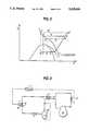
- FIG. 2is a schematic representation of a transcritical vapor compression cycle device constructed in accordance with one preferred embodiment of the invention. This embodiment includes a volume as an integral part of the low side pressure circuit, holding refrigerant in the liquid state;
- FIG. 3is a graph illustrating the relationship of pressure versus enthalpy of the transcritical vapor compression cycle device of FIG. 2 and of FIG. 8 (discussed below) at different operating conditions;
- FIG. 4is a collection of graphs illustrating the control of refrigerating capacity by the method of pressure control in accordance with the present invention. The results shown are measured in a laboratory demonstration system built according to a preferred embodiment of the invention.
- FIG. 5is a graph of test results showing the relationship of temperature versus entropy of the transcritical vapor compression cycle device of FIG. 2, operating at different high side pressures, employing carbon dioxide as a refrigerant;
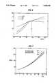
- FIG. 6is a graph illustrating the theoretical relationship between cooling capacity (Q o ), compressor shaft power (P) and their ratio (COP) in a transcritical vapor compression cycle at varying high side pressures, at constant evaporating temperature and gas cooler outlet refrigerant temperature;
- FIG. 7is a graphic illustration of the theoretical relationship between optimum high side pressure, providing maximum ratio between cooling capacity and shaft power, and gas cooler outlet refrigerant temperature at three different evaporating temperatures;
- FIG. 8is a schematic representation similar to FIG. 2 but of a transcritical vapor compression cycle device constructed in accordance with another preferred embodiment of the invention.
- a transcritical vapor compression cycle deviceincludes a refrigerant, the critical temperature of which is between the temperature of the heat inlet and the mean temperature of heat submittal, and a closed working fluid circuit where the refrigerant is circulated.
- Suitable working fluidsmay be, by way of examples, ethylene (C 2 H 4 ), diborane (B 2 H 6 ), carbon dioxide (CO 2 ), ethane (C 2 H 6 ) and nitrogen oxide (N 2 O).
- the closed working fluid circuitincludes a refrigerant flow loop with an integrated storage segment.
- FIG. 2shows a preferred embodiment of this aspect of the invention where the storage segment is an integral part of the low side pressure circuit.
- the flow circuitincludes a compressor 10 connected in series to a heat exchanger (gas coder) 11, a counterflow heat exchanger 12 and a throttling valve 13.
- An evaporating heat exchanger 14, a liquid separator/receiver 16 and the low pressure side of the counterflow heat exchanger 12are connected in flow communication intermediate the throttling valve 13 and the inlet 19 of the compressor 10.
- the liquid receiver 16is connected to the evaporator outlet 15, and the gas phase outlet of the receiver 16 is connected to the counterflow heat exchanger 12.
- the counterflow heat exchanger 12is not absolutely necessary for the functioning of the device but improves its efficiency, in particular its rate of response to a capacity increase requirement. It also serves to return oil to the compressor.
- a liquid phase line from the receiver 16(shown by a broken line in FIG. 2) is connected to the suction line, either before the counterflow heat exchanger 12 at 17 or after it at 18, or anywhere between these points.
- the liquid flowi.e. refrigerant and oil, is controlled by a suitable conventional liquid flow restricting device (not shown in the drawing). By allowing some excess liquid refrigerant to enter the vapor line, a liquid surplus at the evaporator outlet is obtained.
- the refrigerantis compressed to a suitable supercritical pressure in the compressor 10, the compressor outlet 20 is shown as state “a” in FIG. 3.
- the refrigerantis circulated through the heat exchanger 11 where it is cooled to state "b", giving off heat to a suitable cooling agent, e.g. cooling air or water.
- a suitable cooling agente.g. cooling air or water.
- the refrigerantcan be further cooled to state “c" in the counterflow heat exchanger 12, before being throttled to state “d”.
- a two-phase gas/liquid mixtureis formed, shown as state “d” in FIG. 3.
- the refrigerantabsorbs heat in the evaporator 14 by evaporation of the liquid phase.
- the refrigerant vaporcan be superheated in the counterflow heat exchanger 12 to state “f" before it enters the compressor inlet 19, making the cycle complete.
- the evaporator outlet condition "e”will be in the two-phase region due to the liquid surplus at the evaporator outlet.
- Modulation of capacityis accomplished by varying the refrigerant state at the evaporator inlet, i.e. point "d” in FIG. 3.
- the refrigerating capacity per unit of refrigerant mass flowcorresponds to the enthalpy difference between state “d” and state "e". This enthalpy difference is found as a horizontal distance in the enthalpy-pressure diagram of FIG. 3. Throttling is a constant enthalpy process, and thus the enthalpy at point "d” is equal to the enthalpy at point "c".
- the refrigerating capacity (in kW) at constant refrigerant mass flowcan be controlled by varying the enthalpy at point "c".
- the high pressure single-phase refrigerantis not condensed but is reduced in temperature in the heat exchanger 11.
- the terminal temperature of the refrigerant in the heat exchanger(point "b") will be some degrees above the temperature of the entering cooling air or water, if counterflow heat exchange is used.
- the high pressure vaporcan then be cooled a few degrees lower, to point "c" in the counterflow heat exchanger 12.
- the temperature at point "c”will be mainly constant, independent of the pressure level in the high side. Therefore, modulation of device capacity is accomplished by varying the pressure in the high side, while the temperature at point "c” is mainly constant.
- FIG. 3shows a reference cycle (a-b-c-d-e-f), a cycle with reduced capacity due to reduced high side pressure (a'-b'-c'-d'-e-f) and a cycle with increased capacity due to higher high side pressure (a"-b"-c"-d"-e-f).
- the evaporator pressureis assumed to be constant.
- the pressure in the high-pressure sideis independent of temperature, because it is filled with a single phase fluid. To vary the pressure it is necessary to vary the mass of refrigerant in the high side, i.e. to add or remove some of the instant refrigerant charge in the high side. These variations must be taken up by a buffer, to avoid liquid overflow or drying up of the evaporator.
- the refrigerant mass in the high sidecan be increased by temporarily reducing the opening of the throttling valve 13. Due to the incidentally reduced refrigerant flow to the evaporator, the excess liquid fraction at the evaporator outlet 15 will be reduced. The liquid refrigerant flow from the receiver 16 into the suction line is however constant. Consequently, the balance between the liquid flow entering and leaving the receiver 16 is shifted, resulting in a net reduction in receiver liquid content and a corresponding accumulation of refrigerant in the high pressure side of the flow circuit.
- the increase in high side chargeinvolves increasing high side pressure and thereby higher refrigerating capacity. This mass transfer from the low-pressure to the high-pressure side of the circuit will continue until a balance between refrigerating capacity and load is found.
- Opening of the throttling valve 13will increase the excess liquid fraction at the evaporator outlet 15, because the evaporated amount of refrigerant is mainly constant. The difference between this liquid flow entering the receiver and the liquid flow from the receiver into the suction line will accumulate. The result is a net transport of refrigerant charge from the high side to the low side of the flow circuit, with the reduction in the high side charge stored in liquid state in the receiver. By reducing the high side charge and thereby pressure, the capacity of the device is reduced, until a balance is found.
- the embodiment of the invention indicated in FIG. 2has the advantage of simplicity, with capacity control by operation of one valve only. Furthermore, the transcritical vapor compression cycle device built according to this embodiment has a certain self-regulating capability by adapting to changes in cooling load through change in liquid content in the receiver 16, involving changes in high side charge and thus cooling capacity. In addition, the operation with a liquid surplus at the evaporator outlet gives favorable heat transfer characteristics.
- a well known peculiarity of transcritical cycles(operating with a supercritical pressure in the high pressure side of the circuit) is that the coefficient of performance COP, defined as the ratio between the refrigerating capacity and applied compressor shaft power, can be raised by increasing the high side pressure, while the gas cooler outlet refrigerant temperature is maintained mainly constant. This can be illustrated by means of the pressure enthalpy diagram of FIG. 3.
- the COPincreases with increasing high side pressure only up to a certain level and then begins to decline as the extra refrigerating effect no longer fully compensates for the extra work of compression.
- FIG. 6illustrates such a diagram generated for refrigerant CO 2 at constant evaporating and gas cooler outlet temperatures, based on theoretical cycle calculations. At a certain high side pressure corresponding to p' in FIG. 6, the COP reaches a maximum as indicated.
- the detected refrigerant temperature at the gas cooler outlet or some other temperature or parameter corresponding theretoe.g. cooling water inlet temperature, ambient air temperature, cooling or heating load
- the detected refrigerant temperature at the gas cooler outlet or some other temperature or parameter corresponding theretowill be the only significant steering or regulating parameter required as input for control of the throttling valve.
- a back pressure controlleras a throttling valve may give certain advantages in that internal compensation for varying refrigerant mass flow and density is obtained.
- a throttling valve with back-pressure controlwill keep the inlet pressure, i.e. high side pressure, at a particular set point, regardless of refrigerant mass flow and inlet refrigerant temperature.
- the set point of the back-pressure controlleris then regulated by means of an actuator operating in accordance with the predetermined control scheme indicated above.
- Transcritical vapor compression cycle devices built according to the inventioncan be applied in several areas.
- the technologyis well suitable in small and medium-sized stationary and mobile air-conditioning units, small and medium-sized refrigerators/freezers and in smaller heat pump units.
- One of the most promising applicationsis in automotive air-conditioning, where the present need for a new, non-CFC, lightweight and efficient alternative to R12-systems is urgent.
- the practical use of the above embodiment of the present invention for refrigeration or heat pump purposesis illustrated by the following examples, giving test results from a transcritical vapor compression cycle device built according to the embodiment of the invention shown in FIG. 2, employing carbon dioxide (CO 2 ) as refrigerant.
- CO 2carbon dioxide
- a laboratory test deviceused water as a heat source, i.e. the water was refrigerated by heat exchange with boiling CO 2 in the evaporator 14. Water also was used as a cooling agent, being heated by CO 2 in the heat exchanger 11.
- the test deviceincluded a 61 ccm reciprocating compressor 10 and a receiver 16 with a total volume of 4 liters.
- the systemalso included a counterflow heat exchanger 12 and liquid line connection from the receiver to point 17, as indicated in FIG. 2.
- the throttling valve 13was operated manually.
- This exampleshows how control of refrigerating capacity was obtained by varying the position of the throttling valve 13, thereby varying the pressure in the high side of the flow circuit.
- the specific refrigerant enthalpy at the evaporator inletwas controlled, resulting in modulation of refrigerating capacity at constant mass flow.
- the water inlet temperature to the evaporator 14was kept constant at 20° C.
- the water inlet temperature to the heat exchanger 11was kept constant at 35° C. Water circulation was constant both in the evaporator 14 and the heat exchanger 11.
- the compressorran at constant speed.
- FIG. 4shows the variation of refrigerating capacity (Q), compressor shaft work (W), high side pressure (p h ), CO 2 mass flow (m), CO 2 temperature at evaporator outlet (T e ), CO 2 temperature at the outlet of heat exchanger 11 (T b ) and liquid level in the receiver (h) when the throttling valve 13 is operated as indicated at the top of the figure.
- the adjustment of throttling valve positionis the only manipulation.
- capacity (Q)is easily controlled by operating the throttling valve (13). It is further clear that at stable conditions, the circulating mass flow of CO 2 (m) is mainly constant and independent of the cooling capacity.
- the CO 2 temperature at the outlet of heat exchanger 11 (T b )is also mainly constant.
- the graphsshow that the variation of capacity is a result of varying high side pressure (p H ) only. It can also be seen that increased high side pressure involves a reduction in the receiver liquid level (h), due to the CO 2 charge transfer to the high pressure side of the circuit. Finally, it can be noted that the transient period during capacity increase does not involve any significant superheating at the evaporator outlet, i.e. only small fluctuations in T e .
- Table 1shows results from tests run at different water inlet temperatures to heat exchanger 11 (t w ).
- the water inlet temperature to the evaporatorwas kept constant at 20° C., and the compressor ran at constant speed.
- the cooling capacitycan be kept mainly constant when the ambient temperature rises, by increasing the high side pressure.
- the refrigerant mass flowis mainly constant, as shown.
- Increased high side pressuresinvolve a reduction in receiver liquid content, as indicated by the liquid level readings.
- FIG. 5is a graphic representation of transcritical cycles in the entropy/temperature diagram. The cycles shown are based on measurements on the laboratory test device during operation at five different high side pressures. The evaporator pressure was kept constant, and the refrigerant was CO 2 . FIG. 5 provides a good indication of the capacity control principle, indicating changes in specific enthalpy (h) at evaporator inlet caused by variation of the high side pressure (p).
- FIG. 8is similar to FIG. 2 and illustrates a preferred embodiment of the transcritical refrigerating circuit according to this aspect of the invention and comprising a compressor 10 connected in series to a gas cooler 11, an internal counterflow heat exchanger 12 and a throttling valve 13.
- An evaporator 14 and a low pressure liquid receiver 16are connected intermediate the throttling valve and the compressor.
- a temperature sensor at the gas cooler refrigerant outlet 5provides information on the operating conditions of the circuit to a control system 7, e.g. a microprocessor.
- the throttling valve 13is equipped with an actuator 9, and the valve position is automatically modulated in accordance with the predetermined set-point pressure characteristics by the control system 7.
- the circuitmay be provided with a throttling valve 13 based on a simple mechanical back-pressure controller eliminating use of the microprocessor and electronic control of the valve shown in Example 1.
- the regulatormay be equipped with a temperature sensor bulb situated at or near the gas cooler refrigerant outlet 5. Through a membrane arrangement, the pressure resulting from the sensor bulb temperature mechanically adjusts the set-point of the back-pressure controller according to the gas cooler outlet refrigerant temperature. By adjusting spring forces and charge in the sensor, an appropriate relation between the temperature and pressure in the actual regulation range may be obtained.
- the circuitis based on one of the throttling valve control concepts described in Examples 4 or 5, but instead of locating the temperature sensor or sensor bulb at the gas cooler refrigerant outlet, the sensor or sensor bulb measures the inlet temperature of the cooling agent to which heat is rejected.
- the sensor or sensor bulbmeasures the inlet temperature of the cooling agent to which heat is rejected.
- the signal from a temperature sensor or bulbmay be replaced by a signal representing the desired cooling or heating capacity of the system. Due to the correspondence between ambient temperature and load, this signal may serve as a basis for regulating the throttling valve set-point pressure.
Landscapes
- Engineering & Computer Science (AREA)
- Physics & Mathematics (AREA)
- Mechanical Engineering (AREA)
- Thermal Sciences (AREA)
- General Engineering & Computer Science (AREA)
- Chemical & Material Sciences (AREA)
- Chemical Kinetics & Catalysis (AREA)
- Air-Conditioning For Vehicles (AREA)
Abstract
Description
This is a continuation-in-part of U.S. application Ser. No. 571,630 filed Sep. 6, 1990 that corresponds to International Application No. PCT/NO. 89/00089, filed Apr. 30, 1990, now abandoned.
This invention relates to vapor compression cycle devices such as refrigerating, air-conditioning and heat pump systems, operating under transcritical conditions, i.e. operating with a refrigerant compressed to a supercritical pressure at a high pressure side of a compressor, and more particularly, to a method of high side pressure regulation maintaining optimum operation with respect to energy consumption.
A conventional vapor compression cycle device for refrigeration, air-conditioning or heat pump purposes is shown in principle in FIG. 1. The device consists of acompressor 1, acondensing heat exchanger 2, athrottling valve 3 and an evaporatingheat exchanger 4. These components are connected in a closed flow circuit, in which a refrigerant is circulated. The operating principle of a vapor compression cycle device is as follows: The pressure and temperature of the refrigerant vapor are increased by thecompressor 1, before it enters thecondenser 2 where it is cooled and condensed, giving off heat to a secondary coolant. The high-pressure liquid is then throttled to the evaporator pressure and temperature by means of theexpansion valve 3. In theevaporator 4, the refrigerant boils and absorbs heat from its surroundings. The vapor at the evaporator outlet is drawn into the compressor, completing the cycle.
Conventional vapor compression cycle devices use refrigerants (as for instance R-12, CF operating entirely at subcritical pressures. A number of different substances or mixtures of substances may be used as a refrigerant. The choice of refrigerant is, among others, influenced by the condensation temperature, as the critical temperature of the fluid sets the upper limit for the condensation to occur. In order to maintain a reasonable efficiency, it is normally desirable to use a refrigerant with a critical temperature at least 20-30K above the condensation temperature. Near-critical temperatures are normally avoided in design and operation of conventional systems.
The present technology is treated in full detail in the literature, e.g. the Handbooks of American Society of Heating, Refrigerating and Air Conditioning Engineers Inc., Fundamentals 1989 and Refrigeration 1986.
The ozone-depleting effect of presently employed common refrigerants (halocarbons) has resulted in strong international action to reduce or prohibit the use of these fluids. Consequently there is an urgent need for finding alternatives to the present technology.
Control of the conventional vapor compression cycle device is achieved mainly by regulating the mass flow of refrigerant passing through the evaporator. This is done, e.g., by suction line throttling or bypassing the compressor. These methods involve more complicated flow circuit and components, a need for additional equipment and accessories, reduced part-load efficiency and other complications.
A common type of liquid regulation device is a thermostatic expansion valve which is controlled by the superheat at the evaporator outlet. Proper valve operation under varying operating conditions is achieved by using a considerable part of the evaporator to superheat the refrigerant, resulting in a low heat transfer coefficient.
Furthermore, heat rejection in the condenser of the conventional vapor compression cycle device takes place mainly at constant temperature. Therefore, thermodynamic losses occur due to large temperature differences when giving off heat to a secondary coolant with a large temperature increase, as in heat pump applications or when the available secondary coolant flow is small.
The operation of a vapor compression cycle device under transcritical conditions has been formerly practiced to some extent. Up to the time when the halocarbons took over, 40-50 years ago, CO2 was commonly used as a refrigerant, notably in ship refrigeration systems for provisions and cargo. The systems were designed to operate normally at subcritical pressures, with evaporation and condensation. Occasionally, typically when a ship was passing tropical areas, the cooling sea water temperature could be too high to effect normal condensation, and the plant would operate with supercritical conditions on the high side. (Critical temperature for CO2 31° C.). In this situation it was practiced to increase the refrigerant charge on the high side to a point where the pressure at the compressor discharge was raised to 90-100 bar, in order to maintain the cooling capacity at a reasonable level. CO2 refrigeration technology is described in older literature, e.g. P. Ostertag "Kalteprozesse", Springer 1933 or H. J. MacIntire "Refrigeration Engineering", Wiley 1937.
The usual practice in older CO2 -systems was to add the necessary extra charge from separate storage cylinders. A receiver installed after the condenser in the normal way will not be able to provide the functions intended by the present invention.
Another possibility is known from German Patent No. 278,095 (1912). This method involves two-stage compression with intercooling in the supercritical region. Compared to the standard system, this involves installation of an additional compressor or pump, and a heat exchanger.
The textbook "Principles of Refrigeration" of W. B. Gosney (Cambridge Univ. Press 1982) points at some of the peculiarities of near-critical pressure operation. It is suggested that increasing the refrigerant charge in the high-pressure side could be accomplished by temporarily shutting the expansion valve, so as to transfer some charge from the evaporator. But it is emphasized that this would leave the evaporator short of liquid, causing reduced capacity at the time when it is most wanted.
It is therefore an object of one aspect of the present invention to provide a new, improved, simple and effective method and means for regulating high side pressure in a transcritical vapor compression cycle device, avoiding the above shortcomings and disadvantages of the prior art.
Another object of the present invention is to provide a vapor compression cycle device avoiding use of CFC refrigerants, and at the same time offering the possibility to employ several attractive refrigerants with respect to safety, environmental hazards and price.
A further object according to another aspect of the present invention is to provide such a new method and means making possible capacity regulation by operation at mainly constant refrigerant mass flow rate and simple capacity modulation by valve operation.
Still another object of the present invention is to provide a cycle device rejecting heat at gliding temperature, reducing heat-exchange losses in applications where secondary coolant flow is small or when the secondary coolant is to be heated to a relatively high temperature.
It is a yet further object of the present invention to provide a new simple method and means for regulating the high side pressure in a transcritical vapor compression circuit to achieve minimum energy consumption and optimum operation of the system.
The above and other objects of the present invention are achieved by providing a method for regulating the high side pressure in a circuit operating normally at transcritical conditions (i.e. supercritical high side pressure, subcritical low side pressure) where the thermodynamic properties in the supercritical state are utilized to control the high side pressure to regulate the capacity or to achieve minimum energy consumption.
In one application of this aspect of the present invention, the specific enthalpy at the evaporator inlet is regulated by deliberate use of the pressure and/or temperature before throttling for capacity control. Capacity is controlled by varying the refrigerant enthalpy difference in the evaporator, by changing the specific enthalpy of the refrigerant before throttling. In the supercritical state this can be done by varying the pressure and temperature independently. In a preferred embodiment, this modulation of specific enthalpy is done by varying the pressure before throttling. The refrigerant is cooled down as far as it is feasible by means of the available cooling medium, and the pressure regulated to give the required enthalpy.
In accordance with another aspect of the invention a steering or regulating strategy is provided for the throttling valve in the transcritical vapor compression circuit based on application of predetermined values of optimal high side pressure corresponding to detected actual operating conditions of the circuit. In a preferred embodiment of this aspect of the invention, the detection of the operating conditions is done by measurement of a temperature at or near the gas cooler outlet, and the valve position is modulated to predetermined set-point pressure by an appropriate control system.
The invention will now be described in more detail, with reference to the attached drawings, wherein:
FIG. 1 is a schematic representation of a conventional (subcritical) vapor compression cycle device;
FIG. 2 is a schematic representation of a transcritical vapor compression cycle device constructed in accordance with one preferred embodiment of the invention. This embodiment includes a volume as an integral part of the low side pressure circuit, holding refrigerant in the liquid state;
FIG. 3 is a graph illustrating the relationship of pressure versus enthalpy of the transcritical vapor compression cycle device of FIG. 2 and of FIG. 8 (discussed below) at different operating conditions;
FIG. 4 is a collection of graphs illustrating the control of refrigerating capacity by the method of pressure control in accordance with the present invention. The results shown are measured in a laboratory demonstration system built according to a preferred embodiment of the invention;
FIG. 5 is a graph of test results showing the relationship of temperature versus entropy of the transcritical vapor compression cycle device of FIG. 2, operating at different high side pressures, employing carbon dioxide as a refrigerant;
FIG. 6 is a graph illustrating the theoretical relationship between cooling capacity (Qo), compressor shaft power (P) and their ratio (COP) in a transcritical vapor compression cycle at varying high side pressures, at constant evaporating temperature and gas cooler outlet refrigerant temperature;
FIG. 7 is a graphic illustration of the theoretical relationship between optimum high side pressure, providing maximum ratio between cooling capacity and shaft power, and gas cooler outlet refrigerant temperature at three different evaporating temperatures; and
FIG. 8 is a schematic representation similar to FIG. 2 but of a transcritical vapor compression cycle device constructed in accordance with another preferred embodiment of the invention.
A transcritical vapor compression cycle device according to one aspect of the present invention includes a refrigerant, the critical temperature of which is between the temperature of the heat inlet and the mean temperature of heat submittal, and a closed working fluid circuit where the refrigerant is circulated. Suitable working fluids may be, by way of examples, ethylene (C2 H4), diborane (B2 H6), carbon dioxide (CO2), ethane (C2 H6) and nitrogen oxide (N2 O). The closed working fluid circuit includes a refrigerant flow loop with an integrated storage segment.
FIG. 2 shows a preferred embodiment of this aspect of the invention where the storage segment is an integral part of the low side pressure circuit. The flow circuit includes acompressor 10 connected in series to a heat exchanger (gas coder) 11, acounterflow heat exchanger 12 and a throttlingvalve 13. An evaporatingheat exchanger 14, a liquid separator/receiver 16 and the low pressure side of thecounterflow heat exchanger 12 are connected in flow communication intermediate the throttlingvalve 13 and theinlet 19 of thecompressor 10. Theliquid receiver 16 is connected to theevaporator outlet 15, and the gas phase outlet of thereceiver 16 is connected to thecounterflow heat exchanger 12. Thecounterflow heat exchanger 12 is not absolutely necessary for the functioning of the device but improves its efficiency, in particular its rate of response to a capacity increase requirement. It also serves to return oil to the compressor. For this purpose a liquid phase line from the receiver 16 (shown by a broken line in FIG. 2) is connected to the suction line, either before thecounterflow heat exchanger 12 at 17 or after it at 18, or anywhere between these points. The liquid flow, i.e. refrigerant and oil, is controlled by a suitable conventional liquid flow restricting device (not shown in the drawing). By allowing some excess liquid refrigerant to enter the vapor line, a liquid surplus at the evaporator outlet is obtained.
In operation, the refrigerant is compressed to a suitable supercritical pressure in thecompressor 10, thecompressor outlet 20 is shown as state "a" in FIG. 3. The refrigerant is circulated through theheat exchanger 11 where it is cooled to state "b", giving off heat to a suitable cooling agent, e.g. cooling air or water. If desired, the refrigerant can be further cooled to state "c" in thecounterflow heat exchanger 12, before being throttled to state "d". By the pressure reduction in the throttlingvalve 13, a two-phase gas/liquid mixture is formed, shown as state "d" in FIG. 3. The refrigerant absorbs heat in theevaporator 14 by evaporation of the liquid phase. From state "e" at the evaporator outlet, the refrigerant vapor can be superheated in thecounterflow heat exchanger 12 to state "f" before it enters thecompressor inlet 19, making the cycle complete. In the embodiment of the invention shown in FIG. 2, the evaporator outlet condition "e" will be in the two-phase region due to the liquid surplus at the evaporator outlet.
Modulation of capacity is accomplished by varying the refrigerant state at the evaporator inlet, i.e. point "d" in FIG. 3. The refrigerating capacity per unit of refrigerant mass flow corresponds to the enthalpy difference between state "d" and state "e". This enthalpy difference is found as a horizontal distance in the enthalpy-pressure diagram of FIG. 3. Throttling is a constant enthalpy process, and thus the enthalpy at point "d" is equal to the enthalpy at point "c". In consequence, the refrigerating capacity (in kW) at constant refrigerant mass flow can be controlled by varying the enthalpy at point "c".
It should be noted that in the transcritical cycle the high pressure single-phase refrigerant is not condensed but is reduced in temperature in theheat exchanger 11. The terminal temperature of the refrigerant in the heat exchanger (point "b") will be some degrees above the temperature of the entering cooling air or water, if counterflow heat exchange is used. The high pressure vapor can then be cooled a few degrees lower, to point "c" in thecounterflow heat exchanger 12. The result is, however, that at constant cooling air or water inlet temperature, the temperature at point "c" will be mainly constant, independent of the pressure level in the high side. Therefore, modulation of device capacity is accomplished by varying the pressure in the high side, while the temperature at point "c" is mainly constant. The curvature of the isotherms near the critical point result in a variation of enthalpy with pressure, as shown in FIG. 3. This figure shows a reference cycle (a-b-c-d-e-f), a cycle with reduced capacity due to reduced high side pressure (a'-b'-c'-d'-e-f) and a cycle with increased capacity due to higher high side pressure (a"-b"-c"-d"-e-f). The evaporator pressure is assumed to be constant.
The pressure in the high-pressure side is independent of temperature, because it is filled with a single phase fluid. To vary the pressure it is necessary to vary the mass of refrigerant in the high side, i.e. to add or remove some of the instant refrigerant charge in the high side. These variations must be taken up by a buffer, to avoid liquid overflow or drying up of the evaporator.
In the preferred embodiment of the invention indicated in FIG. 2, the refrigerant mass in the high side can be increased by temporarily reducing the opening of the throttlingvalve 13. Due to the incidentally reduced refrigerant flow to the evaporator, the excess liquid fraction at theevaporator outlet 15 will be reduced. The liquid refrigerant flow from thereceiver 16 into the suction line is however constant. Consequently, the balance between the liquid flow entering and leaving thereceiver 16 is shifted, resulting in a net reduction in receiver liquid content and a corresponding accumulation of refrigerant in the high pressure side of the flow circuit. The increase in high side charge involves increasing high side pressure and thereby higher refrigerating capacity. This mass transfer from the low-pressure to the high-pressure side of the circuit will continue until a balance between refrigerating capacity and load is found.
Opening of the throttlingvalve 13 will increase the excess liquid fraction at theevaporator outlet 15, because the evaporated amount of refrigerant is mainly constant. The difference between this liquid flow entering the receiver and the liquid flow from the receiver into the suction line will accumulate. The result is a net transport of refrigerant charge from the high side to the low side of the flow circuit, with the reduction in the high side charge stored in liquid state in the receiver. By reducing the high side charge and thereby pressure, the capacity of the device is reduced, until a balance is found.
Some liquid transported from the receiver into the compressor suction line is also needed to avoid lubricant accumulation in the liquid phase of the receiver.
The embodiment of the invention indicated in FIG. 2 has the advantage of simplicity, with capacity control by operation of one valve only. Furthermore, the transcritical vapor compression cycle device built according to this embodiment has a certain self-regulating capability by adapting to changes in cooling load through change in liquid content in thereceiver 16, involving changes in high side charge and thus cooling capacity. In addition, the operation with a liquid surplus at the evaporator outlet gives favorable heat transfer characteristics.
A well known peculiarity of transcritical cycles (operating with a supercritical pressure in the high pressure side of the circuit) is that the coefficient of performance COP, defined as the ratio between the refrigerating capacity and applied compressor shaft power, can be raised by increasing the high side pressure, while the gas cooler outlet refrigerant temperature is maintained mainly constant. This can be illustrated by means of the pressure enthalpy diagram of FIG. 3. However, the COP increases with increasing high side pressure only up to a certain level and then begins to decline as the extra refrigerating effect no longer fully compensates for the extra work of compression.
Thus, for each set of actual operating conditions defined for instance by evaporating temperature and refrigerant temperature at the gas cooler outlet, a diagram showing the cooling capacity (Qo), compressor shaft power (P) and their ratio (COP) as a function of high side pressure can be provided. FIG. 6 illustrates such a diagram generated for refrigerant CO2 at constant evaporating and gas cooler outlet temperatures, based on theoretical cycle calculations. At a certain high side pressure corresponding to p' in FIG. 6, the COP reaches a maximum as indicated.
By combining such results, i.e. corresponding data for gas cooler outlet refrigerant temperature, evaporating temperature and high side pressure providing maximum COP (p'), at varying operating conditions, a new set of data, as shown in FIG. 7 is provided, which may be applied in the throttling valve steering or regulating strategy. By regulating the high side pressure in accordance with this diagram a maximum ratio between refrigerating capacity and compressor shaft power will always be maintained.
Under maximum load conditions it still may be expedient to operate the system at a discharge pressure well above the level corresponding to maximum COP for a shorter period of time, to limit the compressor volume required and thereby the capital cost and overall energy consumption. At low load conditions, however, a combination of reduced high side pressure to a predetermined optimum level and capacity regulation conducted by a separate control system will provide minimum energy consumption.
Since varying evaporating temperature has a noticeable effect only at high gas cooler outlet refrigerant temperature, this influence may be neglected in practice. Thus, the detected refrigerant temperature at the gas cooler outlet or some other temperature or parameter corresponding thereto (e.g. cooling water inlet temperature, ambient air temperature, cooling or heating load) will be the only significant steering or regulating parameter required as input for control of the throttling valve.
The use of a back pressure controller as a throttling valve may give certain advantages in that internal compensation for varying refrigerant mass flow and density is obtained. A throttling valve with back-pressure control will keep the inlet pressure, i.e. high side pressure, at a particular set point, regardless of refrigerant mass flow and inlet refrigerant temperature. The set point of the back-pressure controller is then regulated by means of an actuator operating in accordance with the predetermined control scheme indicated above.
Transcritical vapor compression cycle devices built according to the invention can be applied in several areas. The technology is well suitable in small and medium-sized stationary and mobile air-conditioning units, small and medium-sized refrigerators/freezers and in smaller heat pump units. One of the most promising applications is in automotive air-conditioning, where the present need for a new, non-CFC, lightweight and efficient alternative to R12-systems is urgent.
The practical use of the above embodiment of the present invention for refrigeration or heat pump purposes is illustrated by the following examples, giving test results from a transcritical vapor compression cycle device built according to the embodiment of the invention shown in FIG. 2, employing carbon dioxide (CO2) as refrigerant. A laboratory test device used water as a heat source, i.e. the water was refrigerated by heat exchange with boiling CO2 in theevaporator 14. Water also was used as a cooling agent, being heated by CO2 in theheat exchanger 11. The test device included a 61ccm reciprocating compressor 10 and areceiver 16 with a total volume of 4 liters. The system also included acounterflow heat exchanger 12 and liquid line connection from the receiver to point 17, as indicated in FIG. 2. The throttlingvalve 13 was operated manually.
This example shows how control of refrigerating capacity was obtained by varying the position of the throttlingvalve 13, thereby varying the pressure in the high side of the flow circuit. By variation of high side pressure, the specific refrigerant enthalpy at the evaporator inlet was controlled, resulting in modulation of refrigerating capacity at constant mass flow. The water inlet temperature to theevaporator 14 was kept constant at 20° C., and the water inlet temperature to theheat exchanger 11 was kept constant at 35° C. Water circulation was constant both in theevaporator 14 and theheat exchanger 11. The compressor ran at constant speed.
FIG. 4 shows the variation of refrigerating capacity (Q), compressor shaft work (W), high side pressure (ph), CO2 mass flow (m), CO2 temperature at evaporator outlet (Te), CO2 temperature at the outlet of heat exchanger 11 (Tb) and liquid level in the receiver (h) when the throttlingvalve 13 is operated as indicated at the top of the figure. The adjustment of throttling valve position is the only manipulation. As shown in FIG. 4, capacity (Q) is easily controlled by operating the throttling valve (13). It is further clear that at stable conditions, the circulating mass flow of CO2 (m) is mainly constant and independent of the cooling capacity. The CO2 temperature at the outlet of heat exchanger 11 (Tb) is also mainly constant. The graphs show that the variation of capacity is a result of varying high side pressure (pH) only. It can also be seen that increased high side pressure involves a reduction in the receiver liquid level (h), due to the CO2 charge transfer to the high pressure side of the circuit. Finally, it can be noted that the transient period during capacity increase does not involve any significant superheating at the evaporator outlet, i.e. only small fluctuations in Te.
With higher water inlet temperature to heat exchanger 11 (e.g. higher ambient temperature), it is necessary to increase the high side pressure to maintain a constant refrigerating capacity. Table 1 shows results from tests run at different water inlet temperatures to heat exchanger 11 (tw). The water inlet temperature to the evaporator was kept constant at 20° C., and the compressor ran at constant speed. As Table 1 shows, the cooling capacity can be kept mainly constant when the ambient temperature rises, by increasing the high side pressure. The refrigerant mass flow is mainly constant, as shown. Increased high side pressures involve a reduction in receiver liquid content, as indicated by the liquid level readings.
TABLE 1 ______________________________________ Inlet temperature (t.sub.w) 35.1 45.9 57.3 °C. Refrigerating capacity (Q) 2.4 2.2 2.2 kW High side pressure (p.sub.H) 84.9 94.3 114.1 bar Mass flow (m) 0.026 0.024 0.020 kg/s Liquid level (h) 171 166 115 mm ______________________________________
FIG. 5 is a graphic representation of transcritical cycles in the entropy/temperature diagram. The cycles shown are based on measurements on the laboratory test device during operation at five different high side pressures. The evaporator pressure was kept constant, and the refrigerant was CO2. FIG. 5 provides a good indication of the capacity control principle, indicating changes in specific enthalpy (h) at evaporator inlet caused by variation of the high side pressure (p).
FIG. 8 is similar to FIG. 2 and illustrates a preferred embodiment of the transcritical refrigerating circuit according to this aspect of the invention and comprising acompressor 10 connected in series to agas cooler 11, an internalcounterflow heat exchanger 12 and a throttlingvalve 13. Anevaporator 14 and a lowpressure liquid receiver 16 are connected intermediate the throttling valve and the compressor. A temperature sensor at the gas cooler refrigerant outlet 5 provides information on the operating conditions of the circuit to acontrol system 7, e.g. a microprocessor. The throttlingvalve 13 is equipped with an actuator 9, and the valve position is automatically modulated in accordance with the predetermined set-point pressure characteristics by thecontrol system 7.
With reference to FIG. 8, the circuit may be provided with a throttlingvalve 13 based on a simple mechanical back-pressure controller eliminating use of the microprocessor and electronic control of the valve shown in Example 1. The regulator may be equipped with a temperature sensor bulb situated at or near the gas cooler refrigerant outlet 5. Through a membrane arrangement, the pressure resulting from the sensor bulb temperature mechanically adjusts the set-point of the back-pressure controller according to the gas cooler outlet refrigerant temperature. By adjusting spring forces and charge in the sensor, an appropriate relation between the temperature and pressure in the actual regulation range may be obtained.
The circuit is based on one of the throttling valve control concepts described in Examples 4 or 5, but instead of locating the temperature sensor or sensor bulb at the gas cooler refrigerant outlet, the sensor or sensor bulb measures the inlet temperature of the cooling agent to which heat is rejected. By counterflow heat exchange, there is a relation between gas cooler refrigerant outlet and cooling medium inlet temperatures, as the refrigerant outlet temperature closely follows the cooling medium inlet temperature. The applied cooling medium is normally ambient air or cooling water.
While the invention has been illustrated and described in the drawings and foregoing description in terms of preferred embodiments it is apparent that changes and modifications may be made therein without departing from the spirit or scope of the invention as set forth in the appended claims. Thus, e.g. in any of the concepts described in Examples 4 or 5 the signal from a temperature sensor or bulb may be replaced by a signal representing the desired cooling or heating capacity of the system. Due to the correspondence between ambient temperature and load, this signal may serve as a basis for regulating the throttling valve set-point pressure.
Claims (26)
1. In a method of operation of a transcritical vapor compression cycle system, said method comprising circulating a refrigerant through a closed circuit by compressing said refrigerant in a compressor to a supercritical pressure, cooling the thus pressurized refrigerant in a cooler, reducing the pressure of said refrigerant by throttling, and evaporating said refrigerant at said reduced pressure in an evaporator, the improvement comprising:
regulating said supercritical pressure of said refrigerant in a high pressure side of said closed circuit by varying the refrigerant mass in said high pressure side by varying the mass of refrigerant in a buffer receiver in said closed circuit, wherein increasing of said pressure is achieved by decreasing said refrigerant mass in said receiver and wherein decreasing of said pressure is achieved by increasing said refrigerant mass in said receiver.
2. The improvement claimed in claim 1, comprising modulating refrigerating capacity by said regulating said high side pressure.
3. The improvement claimed in claim 1, comprising minimizing energy consumption in said system at given refrigerating capacity requirements thereof by said regulating said high side pressure.
4. The improvement claimed in claim 1, comprising providing said buffer receiver in a low pressure side of said closed circuit.
5. The improvement claimed in claim 4, comprising providing said buffer receiver between said evaporator and said compressor.
6. The improvement claimed in claim 1, wherein said regulating comprises controlling a degree of said throttling.
7. The improvement claimed in claim 6, wherein said regulating is achieved solely by controlling said relative degree of throttling.
8. The improvement claimed in claim 6, comprising detecting at least one operating condition of said circuit, and controlling said degree of throttling as a function of said detected operating condition.
9. The improvement claimed in claim 8, wherein said degree of throttling is controlled as a function of said detected operating condition in accordance with a predetermined set of high pressure values to achieve minimum energy consumption at given refrigerating capacity requirements.
10. The improvement claimed in claim 8, wherein said operating condition comprises refrigerant temperature adjacent an outlet of said cooler.
11. The improvement claimed in claim 1, comprising maintaining carbon dioxide in said circuit as said refrigerant.
12. The improvement claimed in claim 1, further comprising passing in heat exchange relationship low pressure refrigerant from an outlet of said evaporator and high pressure refrigerant from an outlet of said cooler, thereby cooling said high pressure refrigerant and superheating said low pressure refrigerant.
13. The improvement claimed in claim 1, comprising circulating refrigerant flow into and from said buffer receiver.
14. In a transcritical vapor compression cycle system comprising a closed circuit circulating therethrough a refrigerant and including a compressor compressing the refrigerant to a supercritical pressure, a cooler cooling the thus pressurized refrigerant, throttling means reducing the pressure of said refrigerant, and an evaporator evaporating said refrigerant at said reduced pressure, the improvement comprising:
means for regulating said supercritical pressure of said refrigerant in a high pressure side of said closed circuit by varying the refrigerant mass in said high pressure side by varying the mass of refrigerant in a buffer receiver in said closed circuit, wherein increasing of said pressure is achieved by decreasing said refrigerant mass in said receiver and wherein decreasing of said pressure is achieved by increasing said refrigerant mass in said receiver.
15. The improvement claimed in claim 14, wherein operation of said regulating means modulates refrigerating capacity of said system.
16. The improvement claimed in claim 14, wherein operation of said regulating means minimizes energy consumption in said system at given refrigerating capacity requirements thereof.
17. The improvement claimed in claim 14, wherein said buffer receiver is provided in a low pressure side of said closed circuit.
18. The improvement claimed in claim 17, wherein said buffer receiver is located between said evaporator and said compressor.
19. The improvement claimed in claim 14, wherein said regulating means comprises means for controlling a degree of opening of said throttling means.
20. The improvement claimed in claim 19, wherein said regulating means is formed solely by said controlling means.
21. The improvement claimed in claim 19, further comprising means for detecting at least one operating condition of said circuit and for operating said controlling means as a function of said detected operation condition.
22. The improvement claimed in claim 21, wherein said detecting means operates said controlling means as a function of said detected operating condition in accordance with a predetermined set of high pressure values to achieve minimum energy consumption at given refrigerating capacity requirements.
23. The improvement claimed in claim 21, wherein said detecting means comprises means for determining refrigerant temperature adjacent an outlet of said cooler.
24. The improvement claimed in claim 14, wherein said refrigerant comprises carbon dioxide.
25. The improvement claimed in claim 14, further comprising means for passing in heat exchange relationship low pressure refrigerant from an outlet of said evaporator and high pressure refrigerant from an outlet of said cooler, thereby cooling said high pressure refrigerant and superheating said low pressure refrigerant.
26. The improvement claimed in claim 14, wherein said buffer receiver includes means for circulating refrigerant flow thereinto and therefrom.
Priority Applications (1)
| Application Number | Priority Date | Filing Date | Title |
|---|---|---|---|
| US07/728,902US5245836A (en) | 1989-01-09 | 1991-07-02 | Method and device for high side pressure regulation in transcritical vapor compression cycle |
Applications Claiming Priority (4)
| Application Number | Priority Date | Filing Date | Title |
|---|---|---|---|
| NO890076 | 1989-01-09 | ||
| NO890076ANO890076D0 (en) | 1989-01-09 | 1989-01-09 | AIR CONDITIONING. |
| US57163090A | 1990-09-06 | 1990-09-06 | |
| US07/728,902US5245836A (en) | 1989-01-09 | 1991-07-02 | Method and device for high side pressure regulation in transcritical vapor compression cycle |
Related Parent Applications (1)
| Application Number | Title | Priority Date | Filing Date |
|---|---|---|---|
| US57163090AContinuation-In-Part | 1989-01-09 | 1990-09-06 |
Publications (1)
| Publication Number | Publication Date |
|---|---|
| US5245836Atrue US5245836A (en) | 1993-09-21 |
Family
ID=27353080
Family Applications (1)
| Application Number | Title | Priority Date | Filing Date |
|---|---|---|---|
| US07/728,902Expired - LifetimeUS5245836A (en) | 1989-01-09 | 1991-07-02 | Method and device for high side pressure regulation in transcritical vapor compression cycle |
Country Status (1)
| Country | Link |
|---|---|
| US (1) | US5245836A (en) |
Cited By (114)
| Publication number | Priority date | Publication date | Assignee | Title |
|---|---|---|---|---|
| US5454228A (en)* | 1994-06-01 | 1995-10-03 | Industrial Technology Research Institute | Refrigeration system for fluid chilling packages |
| US5497631A (en)* | 1991-12-27 | 1996-03-12 | Sinvent A/S | Transcritical vapor compression cycle device with a variable high side volume element |
| NL9401324A (en)* | 1994-08-16 | 1996-04-01 | Urenco Nederland Bv | Cooling process and cooling installation |
| US5685160A (en)* | 1994-09-09 | 1997-11-11 | Mercedes-Benz Ag | Method for operating an air conditioning cooling system for vehicles and a cooling system for carrying out the method |
| WO1999011987A1 (en)* | 1997-08-28 | 1999-03-11 | Empresa Brasileira De Compressores S.A. - Embraco | A refrigeration circuit arrangement for a refrigeration system |
| US5890370A (en)* | 1996-01-25 | 1999-04-06 | Denso Corporation | Refrigerating system with pressure control valve |
| US5924485A (en)* | 1997-05-09 | 1999-07-20 | Denso Corporation | Heat exchanger constructed by a plurality of tubes |
| EP0931991A3 (en)* | 1998-01-21 | 1999-11-17 | Denso Corporation | Supercritical refrigerating system |
| EP0960755A1 (en) | 1998-05-28 | 1999-12-01 | Valeo Climatisation | Air conditioning circuit using a refrigerant fluid in a supercritical state, in particular for a vehicle |
| EP0960756A1 (en) | 1998-05-28 | 1999-12-01 | Valeo Climatisation | Air conditionning device using a refrigerant fluid in a supercritical state |
| US6012300A (en)* | 1997-07-18 | 2000-01-11 | Denso Corporation | Pressure control valve for refrigerating system |
| US6044655A (en)* | 1996-08-22 | 2000-04-04 | Denso Corporation | Vapor compression type refrigerating system |
| US6073454A (en)* | 1998-07-10 | 2000-06-13 | Spauschus Associates, Inc. | Reduced pressure carbon dioxide-based refrigeration system |
| US6092379A (en)* | 1998-07-15 | 2000-07-25 | Denso Corporation | Supercritical refrigerating circuit |
| US6105380A (en)* | 1998-04-16 | 2000-08-22 | Kabushiki Kaisha Toyoda Jidoshokki Seisakusho | Refrigerating system and method of operating the same |
| US6105386A (en)* | 1997-11-06 | 2000-08-22 | Denso Corporation | Supercritical refrigerating apparatus |
| US6112532A (en)* | 1997-01-08 | 2000-09-05 | Norild As | Refrigeration system with closed circuit circulation |
| US6112547A (en)* | 1998-07-10 | 2000-09-05 | Spauschus Associates, Inc. | Reduced pressure carbon dioxide-based refrigeration system |
| EP0971184A3 (en)* | 1998-07-07 | 2000-10-11 | Denso Corporation | Pressure control valve |
| WO2000070277A1 (en) | 1999-05-12 | 2000-11-23 | Volkswagen Aktiengesellschaft | Refrigerant collector for an air conditioning system in a vehicle |
| US6182456B1 (en) | 1998-04-20 | 2001-02-06 | Denso Corporation | Supercritical refrigerating cycle system |
| US6185955B1 (en) | 1998-08-05 | 2001-02-13 | Sanden Corp. | Refrigerating system which can favorably use as a refrigerant, a fluid smaller in specific volume than a general refrigerant |
| RU2164645C2 (en)* | 1996-03-15 | 2001-03-27 | Букин Владимир Григорьевич | Refrigerating machine |
| EP1134517A2 (en) | 2000-03-15 | 2001-09-19 | Denso Corporation | Ejector cycle system with critical refrigerant pressure |
| US6343486B1 (en)* | 1999-06-08 | 2002-02-05 | Mitsubishi Heavy Industries, Ltd. | Supercritical vapor compression cycle |
| EP0908688A3 (en)* | 1997-10-07 | 2002-03-20 | Costan S.P.A. | A refrigeration plant |
| US6363737B1 (en)* | 2000-03-07 | 2002-04-02 | Robby D. Raney | Heat exchanger and method of use therefor |
| EP1202004A1 (en) | 2000-10-30 | 2002-05-02 | Calsonic Kansei Corporation | Cooling cycle and control method thereof |
| EP1046524A3 (en)* | 1999-04-23 | 2002-05-08 | Valeo Klimatechnik GmbH | High pressure gas cooler for a refrigerant circuit of a motor-vehicle air-conditioning system |
| US6385980B1 (en)* | 2000-11-15 | 2002-05-14 | Carrier Corporation | High pressure regulation in economized vapor compression cycles |
| EP0945290A3 (en)* | 1998-03-27 | 2002-05-29 | DaimlerChrysler AG | Method and device for heating and cooling a utility space of an automotive vehicle |
| US6418735B1 (en) | 2000-11-15 | 2002-07-16 | Carrier Corporation | High pressure regulation in transcritical vapor compression cycles |
| EP1207360A3 (en)* | 2000-11-15 | 2002-08-28 | Carrier Corporation | Suction line heat exchanger with a storage tank for a transcritical vapor compression cycle |
| EP1202003A3 (en)* | 2000-10-31 | 2002-10-16 | Modine Manufacturing Company | Refrigeration system with phase separation |
| EP1057669A3 (en)* | 1999-06-05 | 2003-01-15 | Siemens Aktiengesellschaft | Electrically driven compression cooling system with supercritical process cycle |
| US20030010488A1 (en)* | 2001-07-12 | 2003-01-16 | Toshiharu Watanabe | Cooling cycle |
| US6513340B2 (en)* | 1995-04-07 | 2003-02-04 | Fujikoki Corporation | Expansion valve and refrigerating system |
| US6543239B2 (en)* | 1998-07-20 | 2003-04-08 | Visteon Global Technologies, Inc. | Air-conditioning system operated with CO2 |
| US20030102113A1 (en)* | 2001-11-30 | 2003-06-05 | Stephen Memory | Heat exchanger for providing supercritical cooling of a working fluid in a transcritical cooling cycle |
| US6584796B2 (en) | 2000-10-20 | 2003-07-01 | Denso Corporation | Heat pump cycle having internal heat exchanger |
| US6588223B2 (en)* | 1998-07-20 | 2003-07-08 | Visteon Global Technologies, Inc. | Optimized CO2 operated air-conditioning system |
| US6591618B1 (en) | 2002-08-12 | 2003-07-15 | Praxair Technology, Inc. | Supercritical refrigeration system |
| US6626000B1 (en) | 2002-10-30 | 2003-09-30 | Visteon Global Technologies, Inc. | Method and system for electronically controlled high side pressure regulation in a vapor compression cycle |
| US6641371B2 (en) | 2000-08-31 | 2003-11-04 | Nuovo Pignone Holding S.P.A. | Device for continuous regulation of the gas flow rate processed by a reciprocating compressor |
| US6658888B2 (en)* | 2002-04-10 | 2003-12-09 | Carrier Corporation | Method for increasing efficiency of a vapor compression system by compressor cooling |
| US20040003622A1 (en)* | 2002-04-15 | 2004-01-08 | Masami Negishi | Refrigerating cycle system using carbon dioxide as refrigerant |
| US6694763B2 (en) | 2002-05-30 | 2004-02-24 | Praxair Technology, Inc. | Method for operating a transcritical refrigeration system |
| US6698234B2 (en)* | 2002-03-20 | 2004-03-02 | Carrier Corporation | Method for increasing efficiency of a vapor compression system by evaporator heating |
| US6739141B1 (en) | 2003-02-12 | 2004-05-25 | Carrier Corporation | Supercritical pressure regulation of vapor compression system by use of gas cooler fluid pumping device |
| US20040250556A1 (en)* | 2003-06-16 | 2004-12-16 | Sienel Tobias H. | Supercritical pressure regulation of vapor compression system by regulation of expansion machine flowrate |
| US20040255609A1 (en)* | 2001-09-03 | 2004-12-23 | Kare Aflekt | Compression system for cooling and heating purposes |
| US20040255603A1 (en)* | 2003-06-23 | 2004-12-23 | Sivakumar Gopalnarayanan | Refrigeration system having variable speed fan |
| US20040261449A1 (en)* | 2003-06-24 | 2004-12-30 | Memory Stephen B. | Refrigeration system |
| US6848268B1 (en) | 2003-11-20 | 2005-02-01 | Modine Manufacturing Company | CO2 cooling system |
| US20050034473A1 (en)* | 2001-12-21 | 2005-02-17 | Roland Casar | Air-conditioning system for a motor vehicle |
| US20050044864A1 (en)* | 2003-09-02 | 2005-03-03 | Manole Dan M. | Apparatus for the storage and controlled delivery of fluids |
| US20050044865A1 (en)* | 2003-09-02 | 2005-03-03 | Manole Dan M. | Multi-stage vapor compression system with intermediate pressure vessel |
| WO2005026854A1 (en)* | 2003-09-05 | 2005-03-24 | Carrier Corporation | Supercritical pressure regulation of vapor compression system |
| US20050066675A1 (en)* | 2003-09-25 | 2005-03-31 | Manole Dan M. | Method and apparatus for determining supercritical pressure in a heat exchanger |
| US20050109486A1 (en)* | 2003-11-20 | 2005-05-26 | Memory Stephen B. | Suction line heat exchanger for CO2 cooling system |
| US20050132729A1 (en)* | 2003-12-23 | 2005-06-23 | Manole Dan M. | Transcritical vapor compression system and method of operating including refrigerant storage tank and non-variable expansion device |
| US20050132732A1 (en)* | 2003-12-19 | 2005-06-23 | Eisenhower Bryan A. | Vapor compression system startup method |
| US20050132731A1 (en)* | 2003-12-18 | 2005-06-23 | Calsonic Kansei Corporation | Air conditioning system, vehicular air conditioning system and control method of vehicular air conditioning system |
| US20050150248A1 (en)* | 2004-01-13 | 2005-07-14 | Manole Dan M. | Method and apparatus for control of carbon dioxide gas cooler pressure by use of a capillary tube |
| US20050210684A1 (en)* | 1999-10-15 | 2005-09-29 | Newman Martin H | Atomically sharp edged cutting blades and methods for making same |
| US20060056982A1 (en)* | 2002-06-05 | 2006-03-16 | Sanyo Electric Co., Ltd. | Internal intermediate pressure multistage compression type rotary compressor, manufacturing method thereof and displacement ratio setting method |
| US20060059945A1 (en)* | 2004-09-13 | 2006-03-23 | Lalit Chordia | Method for single-phase supercritical carbon dioxide cooling |
| US20060107685A1 (en)* | 2004-11-19 | 2006-05-25 | Carrier Corporation | Reheat dehumidification system in variable speed applications |
| US7076964B2 (en)* | 2001-10-03 | 2006-07-18 | Denso Corporation | Super-critical refrigerant cycle system and water heater using the same |
| US20060198744A1 (en)* | 2005-03-03 | 2006-09-07 | Carrier Corporation | Skipping frequencies for variable speed controls |
| US20060225444A1 (en)* | 2005-04-08 | 2006-10-12 | Carrier Corporation | Refrigerant system with variable speed compressor and reheat function |
| US20060230773A1 (en)* | 2005-04-14 | 2006-10-19 | Carrier Corporation | Method for determining optimal coefficient of performance in a transcritical vapor compression system |
| US20070012070A1 (en)* | 2005-07-15 | 2007-01-18 | Frank Vetter | Air-conditioning loop with gas accumulator |
| US20070022765A1 (en)* | 2005-07-28 | 2007-02-01 | Carrier Corporation | Controlling a voltage-to-frequency ratio for a variable speed drive in refrigerant systems |
| US20070033957A1 (en)* | 2005-08-09 | 2007-02-15 | Carrier Corporation | Automated drive for fan and refrigerant system |
| USRE39597E1 (en) | 2001-07-02 | 2007-05-01 | Carrier Corporation | Variable speed drive chiller system |
| US20070130988A1 (en)* | 2005-12-12 | 2007-06-14 | Sanden Corporation | Vapor compression refrigerating systems |
| WO2007088012A1 (en)* | 2006-02-03 | 2007-08-09 | Airbus Deutschland Gmbh | Cooling system |
| US20080041094A1 (en)* | 2003-06-11 | 2008-02-21 | Sienel Tobias H | Supercritical pressure regulation of economized refrigeration system by use of an interstage accumulator |
| CN100387916C (en)* | 2003-06-04 | 2008-05-14 | 三洋电机株式会社 | Cooling device and method for setting the amount of refrigerant charged in the cooling device |
| US20080196445A1 (en)* | 2005-06-07 | 2008-08-21 | Alexander Lifson | Variable Speed Compressor Motor Control for Low Speed Operation |
| US20080223057A1 (en)* | 2005-10-26 | 2008-09-18 | Alexander Lifson | Refrigerant System with Pulse Width Modulated Components and Variable Speed Compressor |
| US20080223074A1 (en)* | 2007-03-09 | 2008-09-18 | Johnson Controls Technology Company | Refrigeration system |
| US20080314057A1 (en)* | 2005-05-04 | 2008-12-25 | Alexander Lifson | Refrigerant System With Variable Speed Scroll Compressor and Economizer Circuit |
| US20090113903A1 (en)* | 2007-11-02 | 2009-05-07 | Babkin Alexei V | Cooling methods and systems using supercritical fluids |
| US20090133856A1 (en)* | 2005-11-16 | 2009-05-28 | Videto Brian D | Airflow management system in a hvac unit including two fans of different diameters |
| US20090151369A1 (en)* | 2006-04-25 | 2009-06-18 | Alexander Lifson | Malfunction detection for fan or pump refrigerant system |
| US20090272128A1 (en)* | 2008-05-02 | 2009-11-05 | Kysor Industrial Corporation | Cascade cooling system with intercycle cooling |
| US20100077777A1 (en)* | 2006-10-27 | 2010-04-01 | Carrier Corporation | Economized refrigeration cycle with expander |
| US7811071B2 (en) | 2007-10-24 | 2010-10-12 | Emerson Climate Technologies, Inc. | Scroll compressor for carbon dioxide refrigerant |
| US7832220B1 (en)* | 2003-01-14 | 2010-11-16 | Earth To Air Systems, Llc | Deep well direct expansion heating and cooling system |
| US20100288210A1 (en)* | 2007-11-28 | 2010-11-18 | Brueckner Jan | Method for operating a once-through steam generator and forced-flow steam generator |
| US20110041523A1 (en)* | 2008-05-14 | 2011-02-24 | Carrier Corporation | Charge management in refrigerant vapor compression systems |
| US20110137522A1 (en)* | 2008-05-09 | 2011-06-09 | C.R.F. Societa Consortile Per Azioni | Control of a condenser fan of an automotive air-conditioning system |
| US20120198868A1 (en)* | 2009-11-25 | 2012-08-09 | Carrier Corporation | Low suction pressure protection for refrigerant vapor compression system |
| US8745996B2 (en) | 2008-10-01 | 2014-06-10 | Carrier Corporation | High-side pressure control for transcritical refrigeration system |
| US9194615B2 (en) | 2013-04-05 | 2015-11-24 | Marc-Andre Lesmerises | CO2 cooling system and method for operating same |
| US9776473B2 (en) | 2012-09-20 | 2017-10-03 | Thermo King Corporation | Electrical transport refrigeration system |
| US20180187934A1 (en)* | 2015-08-17 | 2018-07-05 | Electrolux Appliances Aktiebolaget | Control method for a cooling device |
| US10041713B1 (en) | 1999-08-20 | 2018-08-07 | Hudson Technologies, Inc. | Method and apparatus for measuring and improving efficiency in refrigeration systems |
| US10088202B2 (en) | 2009-10-23 | 2018-10-02 | Carrier Corporation | Refrigerant vapor compression system operation |
| US10234181B2 (en) | 2013-11-18 | 2019-03-19 | Carrier Corporation | Flash gas bypass evaporator |
| WO2019178641A1 (en)* | 2018-03-23 | 2019-09-26 | Avance Energy Solutions Pty Ltd | An air-conditioning integrated parallel compression transcritical refrigeration rack system and control methods thereof |
| US10543737B2 (en) | 2015-12-28 | 2020-01-28 | Thermo King Corporation | Cascade heat transfer system |
| US10690389B2 (en) | 2008-10-23 | 2020-06-23 | Toromont Industries Ltd | CO2 refrigeration system |
| CN112368523A (en)* | 2018-07-06 | 2021-02-12 | 三菱重工制冷空调系统株式会社 | Refrigeration cycle apparatus and control method thereof |
| WO2021225755A1 (en)* | 2020-05-05 | 2021-11-11 | Echogen Power Systems, Llc | Split expansion heat pump cycle |
| US11408658B2 (en) | 2016-02-10 | 2022-08-09 | Carrier Corporation | Power management for CO2 transportation refrigeration system |
| US11479082B2 (en)* | 2018-02-16 | 2022-10-25 | Jaguar Land Rover Limited | System and method for refrigerant management in an electric vehicle |
| US20230124335A1 (en)* | 2020-06-10 | 2023-04-20 | Mitsubishi Electric Corporation | Refrigeration cycle apparatus |
| US11656005B2 (en) | 2015-04-29 | 2023-05-23 | Gestion Marc-André Lesmerises Inc. | CO2 cooling system and method for operating same |
| US20230182526A1 (en)* | 2021-12-15 | 2023-06-15 | Hyundai Motor Company | Heat Exchanger and Refrigerant Module of Integrated Thermal Management System for Vehicle Including Same |
| US11981185B2 (en) | 2021-11-11 | 2024-05-14 | Hyundai Motor Company | Refrigerant module of integrated thermal management system for vehicle |
| US11993134B2 (en) | 2021-11-11 | 2024-05-28 | Hyundai Motor Company | Refrigerant module of integrated thermal management system for vehicle |
Citations (31)
| Publication number | Priority date | Publication date | Assignee | Title |
|---|---|---|---|---|
| DE278095C (en)* | ||||
| US1408453A (en)* | 1921-01-24 | 1922-03-07 | Justus C Goosmann | Refrigerating apparatus |
| US1591302A (en)* | 1925-06-09 | 1926-07-06 | William S Franklin | Automatic expansion valve for refrigerating systems |
| US2219815A (en)* | 1939-01-18 | 1940-10-29 | Carrier Corp | Refrigerating and heating system |
| US2482171A (en)* | 1945-10-04 | 1949-09-20 | Gen Engineering & Mfg Company | Flow control device for refrigeration apparatus |
| US2617265A (en)* | 1951-01-16 | 1952-11-11 | V C Patterson & Associates Inc | Oil removal system for refrigeration apparatus |
| US2778607A (en)* | 1954-08-17 | 1957-01-22 | Leoni Renato Quintilii | Recovery of heat contained in cooling fluid of transformers and alternators |
| DE1021868B (en)* | 1955-03-31 | 1958-01-02 | Waggon U Maschinenfabriken G M | Device for the operation of refrigeration systems |
| US2901894A (en)* | 1955-03-10 | 1959-09-01 | Jr Elmer W Zearfoss | Refrigerant control means |
| US3234738A (en)* | 1962-10-11 | 1966-02-15 | Wilfred L Cook | Low temperature power cycle |
| GB1042975A (en)* | 1962-07-26 | 1966-09-21 | Philips Nv | Improvements in or relating to methods of absorbing thermal energy at low temperatures |
| US3365905A (en)* | 1966-03-07 | 1968-01-30 | Jackes Evans Mfg Company | Compressor suction line by-pass means |
| US3400555A (en)* | 1966-05-02 | 1968-09-10 | American Gas Ass | Refrigeration system employing heat actuated compressor |
| US3413815A (en)* | 1966-05-02 | 1968-12-03 | American Gas Ass | Heat-actuated regenerative compressor for refrigerating systems |
| US3513663A (en)* | 1968-05-08 | 1970-05-26 | James B Martin Jr | Apparatus for heating and cooling liquids |
| US3597183A (en)* | 1967-05-15 | 1971-08-03 | Allied Chem | Trifluoromethane-ethane azeotropic composition |
| US3638446A (en)* | 1969-06-27 | 1972-02-01 | Robert T Palmer | Low ambient control of subcooling control valve |
| US3858407A (en)* | 1973-08-14 | 1975-01-07 | Virginia Chemicals Inc | Combination liquid trapping suction accumulator and evaporator pressure regulator device |
| US3872682A (en)* | 1974-03-18 | 1975-03-25 | Northfield Freezing Systems In | Closed system refrigeration or heat exchange |
| DE2401120A1 (en)* | 1974-01-10 | 1975-07-17 | Siemen & Hinsch Gmbh | PROCEDURE AND SYSTEM FOR FILLING LIQUID CIRCUITS |
| DE2604043A1 (en)* | 1975-02-05 | 1976-08-19 | Nishinihon Seiki Seisakusho Kk | DEFROSTING SYSTEM FOR A COMPRESSOR COOLING MACHINE |
| US4019679A (en)* | 1974-12-20 | 1977-04-26 | Interliz Anstalt | Thermostatically controlled heating arrangement including a heat pump |
| US4205532A (en)* | 1977-05-02 | 1980-06-03 | Commercial Refrigeration (Wiltshire) Limited | Apparatus for and method of transferring heat |
| US4439996A (en)* | 1982-01-08 | 1984-04-03 | Whirlpool Corporation | Binary refrigerant system with expansion valve control |
| EP0174027A2 (en)* | 1984-09-06 | 1986-03-12 | Matsushita Electric Industrial Co., Ltd. | Heat pump apparatus |
| US4631926A (en)* | 1985-08-23 | 1986-12-30 | Goldshtein Lev I | Method of obtaining low temperatures and apparatus for implementing the same |
| US4702086A (en)* | 1986-06-11 | 1987-10-27 | Turbo Coils Inc. | Refrigeration system with hot gas pre-cooler |
| SU1521998A1 (en)* | 1987-01-05 | 1989-11-15 | Одесский Технологический Институт Холодильной Промышленности | Cascade-type refrigerator |
| WO1990007683A1 (en)* | 1989-01-09 | 1990-07-12 | Sinvent As | Trans-critical vapour compression cycle device |
| SE463533B (en)* | 1987-04-13 | 1990-12-03 | Handelsbolaget Heliovent | Arrangement for temperature-based refrigerant control in a heat pump |
| US5042262A (en)* | 1990-05-08 | 1991-08-27 | Liquid Carbonic Corporation | Food freezer |
- 1991
- 1991-07-02USUS07/728,902patent/US5245836A/ennot_activeExpired - Lifetime
Patent Citations (32)
| Publication number | Priority date | Publication date | Assignee | Title |
|---|---|---|---|---|
| DE278095C (en)* | ||||
| US1408453A (en)* | 1921-01-24 | 1922-03-07 | Justus C Goosmann | Refrigerating apparatus |
| US1591302A (en)* | 1925-06-09 | 1926-07-06 | William S Franklin | Automatic expansion valve for refrigerating systems |
| US2219815A (en)* | 1939-01-18 | 1940-10-29 | Carrier Corp | Refrigerating and heating system |
| US2482171A (en)* | 1945-10-04 | 1949-09-20 | Gen Engineering & Mfg Company | Flow control device for refrigeration apparatus |
| US2617265A (en)* | 1951-01-16 | 1952-11-11 | V C Patterson & Associates Inc | Oil removal system for refrigeration apparatus |
| US2778607A (en)* | 1954-08-17 | 1957-01-22 | Leoni Renato Quintilii | Recovery of heat contained in cooling fluid of transformers and alternators |
| US2901894A (en)* | 1955-03-10 | 1959-09-01 | Jr Elmer W Zearfoss | Refrigerant control means |
| DE1021868B (en)* | 1955-03-31 | 1958-01-02 | Waggon U Maschinenfabriken G M | Device for the operation of refrigeration systems |
| GB1042975A (en)* | 1962-07-26 | 1966-09-21 | Philips Nv | Improvements in or relating to methods of absorbing thermal energy at low temperatures |
| US3234738A (en)* | 1962-10-11 | 1966-02-15 | Wilfred L Cook | Low temperature power cycle |
| US3365905A (en)* | 1966-03-07 | 1968-01-30 | Jackes Evans Mfg Company | Compressor suction line by-pass means |
| US3400555A (en)* | 1966-05-02 | 1968-09-10 | American Gas Ass | Refrigeration system employing heat actuated compressor |
| US3413815A (en)* | 1966-05-02 | 1968-12-03 | American Gas Ass | Heat-actuated regenerative compressor for refrigerating systems |
| US3597183A (en)* | 1967-05-15 | 1971-08-03 | Allied Chem | Trifluoromethane-ethane azeotropic composition |
| US3513663A (en)* | 1968-05-08 | 1970-05-26 | James B Martin Jr | Apparatus for heating and cooling liquids |
| US3638446A (en)* | 1969-06-27 | 1972-02-01 | Robert T Palmer | Low ambient control of subcooling control valve |
| US3858407A (en)* | 1973-08-14 | 1975-01-07 | Virginia Chemicals Inc | Combination liquid trapping suction accumulator and evaporator pressure regulator device |
| DE2401120A1 (en)* | 1974-01-10 | 1975-07-17 | Siemen & Hinsch Gmbh | PROCEDURE AND SYSTEM FOR FILLING LIQUID CIRCUITS |
| US3872682A (en)* | 1974-03-18 | 1975-03-25 | Northfield Freezing Systems In | Closed system refrigeration or heat exchange |
| US4019679A (en)* | 1974-12-20 | 1977-04-26 | Interliz Anstalt | Thermostatically controlled heating arrangement including a heat pump |
| DE2604043A1 (en)* | 1975-02-05 | 1976-08-19 | Nishinihon Seiki Seisakusho Kk | DEFROSTING SYSTEM FOR A COMPRESSOR COOLING MACHINE |
| US4205532A (en)* | 1977-05-02 | 1980-06-03 | Commercial Refrigeration (Wiltshire) Limited | Apparatus for and method of transferring heat |
| US4439996A (en)* | 1982-01-08 | 1984-04-03 | Whirlpool Corporation | Binary refrigerant system with expansion valve control |
| EP0174027A2 (en)* | 1984-09-06 | 1986-03-12 | Matsushita Electric Industrial Co., Ltd. | Heat pump apparatus |
| US4679403A (en)* | 1984-09-06 | 1987-07-14 | Matsushita Electric Industrial Co., Ltd. | Heat pump apparatus |
| US4631926A (en)* | 1985-08-23 | 1986-12-30 | Goldshtein Lev I | Method of obtaining low temperatures and apparatus for implementing the same |
| US4702086A (en)* | 1986-06-11 | 1987-10-27 | Turbo Coils Inc. | Refrigeration system with hot gas pre-cooler |
| SU1521998A1 (en)* | 1987-01-05 | 1989-11-15 | Одесский Технологический Институт Холодильной Промышленности | Cascade-type refrigerator |
| SE463533B (en)* | 1987-04-13 | 1990-12-03 | Handelsbolaget Heliovent | Arrangement for temperature-based refrigerant control in a heat pump |
| WO1990007683A1 (en)* | 1989-01-09 | 1990-07-12 | Sinvent As | Trans-critical vapour compression cycle device |
| US5042262A (en)* | 1990-05-08 | 1991-08-27 | Liquid Carbonic Corporation | Food freezer |
Non-Patent Citations (11)
| Title |
|---|
| "Cooling Machinery and Apparatuses", Gntimash, Moscow 1946, p. 4, FIGS. 28-29. |
| "Principles of Refrigeration": by W. B. Gosney; Cambridge University Press, 1982. |
| Cooling Machinery and Apparatuses , Gntimash, Moscow 1946, p. 4, FIGS. 28 29.* |
| Kalteprozesse Dargestellt Mit Hilfe Der Entropietofel, by Dipl Ing. Prof. P. Ostertag, Berlin, Verlag Von Julius Springer, 1933 (w/translation).* |
| Kalteprozesse Dargestellt Mit Hilfe Der Entropietofel, by Dipl-Ing. Prof. P. Ostertag, Berlin, Verlag Von Julius Springer, 1933 (w/translation). |
| Patent Abstracts of Japan, vol. 13, No. 489, M888, abstract of JP 01 193561, publ. 1989 08 03.* |
| Patent Abstracts of Japan, vol. 13, No. 489, M888, abstract of JP 01-193561, publ. 1989-08-03. |
| Principles of Refrigeration : by W. B. Gosney; Cambridge University Press, 1982.* |
| Refrigeration Engineering by H. J. MacIntire pp. 60 61 John Wiley & Sons Inc. 1937.* |
| Refrigeration Engineering by H. J. MacIntire pp. 60-61 John Wiley & Sons Inc. 1937. |
| Refrigeration Engineering, by H. J. MacIntire, 1937.* |
Cited By (176)
| Publication number | Priority date | Publication date | Assignee | Title |
|---|---|---|---|---|
| US5497631A (en)* | 1991-12-27 | 1996-03-12 | Sinvent A/S | Transcritical vapor compression cycle device with a variable high side volume element |
| US5454228A (en)* | 1994-06-01 | 1995-10-03 | Industrial Technology Research Institute | Refrigeration system for fluid chilling packages |
| NL9401324A (en)* | 1994-08-16 | 1996-04-01 | Urenco Nederland Bv | Cooling process and cooling installation |
| US5685160A (en)* | 1994-09-09 | 1997-11-11 | Mercedes-Benz Ag | Method for operating an air conditioning cooling system for vehicles and a cooling system for carrying out the method |
| US6513340B2 (en)* | 1995-04-07 | 2003-02-04 | Fujikoki Corporation | Expansion valve and refrigerating system |
| US5890370A (en)* | 1996-01-25 | 1999-04-06 | Denso Corporation | Refrigerating system with pressure control valve |
| RU2164645C2 (en)* | 1996-03-15 | 2001-03-27 | Букин Владимир Григорьевич | Refrigerating machine |
| EP0837291A3 (en)* | 1996-08-22 | 2000-10-04 | Denso Corporation | Vapor compression type refrigerating system |
| US6044655A (en)* | 1996-08-22 | 2000-04-04 | Denso Corporation | Vapor compression type refrigerating system |
| US6112532A (en)* | 1997-01-08 | 2000-09-05 | Norild As | Refrigeration system with closed circuit circulation |
| US5924485A (en)* | 1997-05-09 | 1999-07-20 | Denso Corporation | Heat exchanger constructed by a plurality of tubes |
| US6012300A (en)* | 1997-07-18 | 2000-01-11 | Denso Corporation | Pressure control valve for refrigerating system |
| WO1999011987A1 (en)* | 1997-08-28 | 1999-03-11 | Empresa Brasileira De Compressores S.A. - Embraco | A refrigeration circuit arrangement for a refrigeration system |
| EP0908688A3 (en)* | 1997-10-07 | 2002-03-20 | Costan S.P.A. | A refrigeration plant |
| US6105386A (en)* | 1997-11-06 | 2000-08-22 | Denso Corporation | Supercritical refrigerating apparatus |
| EP0931991A3 (en)* | 1998-01-21 | 1999-11-17 | Denso Corporation | Supercritical refrigerating system |
| US6134900A (en)* | 1998-01-21 | 2000-10-24 | Denso Corporation | Supercritical refrigerating system |
| EP0945290A3 (en)* | 1998-03-27 | 2002-05-29 | DaimlerChrysler AG | Method and device for heating and cooling a utility space of an automotive vehicle |
| US6564567B2 (en) | 1998-03-27 | 2003-05-20 | Daimlerchrysler Ag | Method and device for heating and cooling a compartment of a motor vehicle |
| EP0952412A3 (en)* | 1998-04-16 | 2002-01-16 | Kabushiki Kaisha Toyota Jidoshokki | Refrigerating system and method of operating the same |
| US6105380A (en)* | 1998-04-16 | 2000-08-22 | Kabushiki Kaisha Toyoda Jidoshokki Seisakusho | Refrigerating system and method of operating the same |
| US6182456B1 (en) | 1998-04-20 | 2001-02-06 | Denso Corporation | Supercritical refrigerating cycle system |
| FR2779215A1 (en) | 1998-05-28 | 1999-12-03 | Valeo Climatisation | AIR CONDITIONING CIRCUIT USING A SUPERCRITICAL REFRIGERANT FLUID, PARTICULARLY FOR VEHICLE |
| EP0960756A1 (en) | 1998-05-28 | 1999-12-01 | Valeo Climatisation | Air conditionning device using a refrigerant fluid in a supercritical state |
| US6178761B1 (en) | 1998-05-28 | 2001-01-30 | Valeo Climatisation | Air conditioning circuit using a refrigerant fluid in the supercritical state, in particular for a vehicle |
| US6679320B2 (en) | 1998-05-28 | 2004-01-20 | Valeo Climatisation | Vehicle air conditioning circuit using a refrigerant fluid in the supercritical state |
| FR2779216A1 (en) | 1998-05-28 | 1999-12-03 | Valeo Climatisation | VEHICLE AIR CONDITIONING DEVICE USING A SUPERCRITICAL REFRIGERANT FLUID |
| EP0960755A1 (en) | 1998-05-28 | 1999-12-01 | Valeo Climatisation | Air conditioning circuit using a refrigerant fluid in a supercritical state, in particular for a vehicle |
| EP0971184A3 (en)* | 1998-07-07 | 2000-10-11 | Denso Corporation | Pressure control valve |
| US6189326B1 (en) | 1998-07-07 | 2001-02-20 | Denso Corporation | Pressure control valve |
| US6073454A (en)* | 1998-07-10 | 2000-06-13 | Spauschus Associates, Inc. | Reduced pressure carbon dioxide-based refrigeration system |
| US6112547A (en)* | 1998-07-10 | 2000-09-05 | Spauschus Associates, Inc. | Reduced pressure carbon dioxide-based refrigeration system |
| US6092379A (en)* | 1998-07-15 | 2000-07-25 | Denso Corporation | Supercritical refrigerating circuit |
| US6543239B2 (en)* | 1998-07-20 | 2003-04-08 | Visteon Global Technologies, Inc. | Air-conditioning system operated with CO2 |
| US6588223B2 (en)* | 1998-07-20 | 2003-07-08 | Visteon Global Technologies, Inc. | Optimized CO2 operated air-conditioning system |
| US6185955B1 (en) | 1998-08-05 | 2001-02-13 | Sanden Corp. | Refrigerating system which can favorably use as a refrigerant, a fluid smaller in specific volume than a general refrigerant |
| EP1046524A3 (en)* | 1999-04-23 | 2002-05-08 | Valeo Klimatechnik GmbH | High pressure gas cooler for a refrigerant circuit of a motor-vehicle air-conditioning system |
| WO2000070277A1 (en) | 1999-05-12 | 2000-11-23 | Volkswagen Aktiengesellschaft | Refrigerant collector for an air conditioning system in a vehicle |
| EP1057669A3 (en)* | 1999-06-05 | 2003-01-15 | Siemens Aktiengesellschaft | Electrically driven compression cooling system with supercritical process cycle |
| US6343486B1 (en)* | 1999-06-08 | 2002-02-05 | Mitsubishi Heavy Industries, Ltd. | Supercritical vapor compression cycle |
| US10041713B1 (en) | 1999-08-20 | 2018-08-07 | Hudson Technologies, Inc. | Method and apparatus for measuring and improving efficiency in refrigeration systems |
| US20050210684A1 (en)* | 1999-10-15 | 2005-09-29 | Newman Martin H | Atomically sharp edged cutting blades and methods for making same |
| US6363737B1 (en)* | 2000-03-07 | 2002-04-02 | Robby D. Raney | Heat exchanger and method of use therefor |
| EP1134517A3 (en)* | 2000-03-15 | 2002-07-10 | Denso Corporation | Ejector cycle system with critical refrigerant pressure |
| US6574987B2 (en) | 2000-03-15 | 2003-06-10 | Denso Corporation | Ejector cycle system with critical refrigerant pressure |
| EP1134517A2 (en) | 2000-03-15 | 2001-09-19 | Denso Corporation | Ejector cycle system with critical refrigerant pressure |
| US6477857B2 (en) | 2000-03-15 | 2002-11-12 | Denso Corporation | Ejector cycle system with critical refrigerant pressure |
| EP1589301B1 (en)* | 2000-03-15 | 2017-06-14 | Denso Corporation | Ejector cycle system with critical refrigerant pressure |
| US6641371B2 (en) | 2000-08-31 | 2003-11-04 | Nuovo Pignone Holding S.P.A. | Device for continuous regulation of the gas flow rate processed by a reciprocating compressor |
| US6584796B2 (en) | 2000-10-20 | 2003-07-01 | Denso Corporation | Heat pump cycle having internal heat exchanger |
| US6523360B2 (en) | 2000-10-30 | 2003-02-25 | Calsonic Kansei Corporation | Cooling cycle and control method thereof |
| EP1202004A1 (en) | 2000-10-30 | 2002-05-02 | Calsonic Kansei Corporation | Cooling cycle and control method thereof |
| EP1202003A3 (en)* | 2000-10-31 | 2002-10-16 | Modine Manufacturing Company | Refrigeration system with phase separation |
| CN100430671C (en)* | 2000-11-15 | 2008-11-05 | 开利公司 | A transcritical vapor compression system and its high-pressure regulating device |
| EP1207361A3 (en)* | 2000-11-15 | 2002-08-28 | Carrier Corporation | High pressure regulation in a transcritical vapor compression cycle |
| EP1207360A3 (en)* | 2000-11-15 | 2002-08-28 | Carrier Corporation | Suction line heat exchanger with a storage tank for a transcritical vapor compression cycle |
| US6418735B1 (en) | 2000-11-15 | 2002-07-16 | Carrier Corporation | High pressure regulation in transcritical vapor compression cycles |
| US6385980B1 (en)* | 2000-11-15 | 2002-05-14 | Carrier Corporation | High pressure regulation in economized vapor compression cycles |
| US6606867B1 (en) | 2000-11-15 | 2003-08-19 | Carrier Corporation | Suction line heat exchanger storage tank for transcritical cycles |
| AU766121B2 (en)* | 2000-11-15 | 2003-10-09 | Carrier Corporation | High pressure regulation in economized vapor compression cycles |
| USRE39597E1 (en) | 2001-07-02 | 2007-05-01 | Carrier Corporation | Variable speed drive chiller system |
| FR2827224A1 (en) | 2001-07-12 | 2003-01-17 | Calsonic Kansei Corp | Cooling cycle, for use in automotive air-conditioning system, includes heat exchanger arranged between compressor and throttle valve, so as to exchange heat between compressed refrigerant and coolant of engine |
| US20060005941A1 (en)* | 2001-07-12 | 2006-01-12 | Calsonic Kansei Corporation | Cooling cycle |
| US20030010488A1 (en)* | 2001-07-12 | 2003-01-16 | Toshiharu Watanabe | Cooling cycle |
| US20060254748A1 (en)* | 2001-07-12 | 2006-11-16 | Calsonic Kansei Corporation | Cooling cycle |
| US7131291B2 (en)* | 2001-09-03 | 2006-11-07 | Sinvent As | Compression system for cooling and heating purposes |
| US20040255609A1 (en)* | 2001-09-03 | 2004-12-23 | Kare Aflekt | Compression system for cooling and heating purposes |
| US7076964B2 (en)* | 2001-10-03 | 2006-07-18 | Denso Corporation | Super-critical refrigerant cycle system and water heater using the same |
| US20030102113A1 (en)* | 2001-11-30 | 2003-06-05 | Stephen Memory | Heat exchanger for providing supercritical cooling of a working fluid in a transcritical cooling cycle |
| US7231776B2 (en)* | 2001-12-21 | 2007-06-19 | Diamlerchrysler Ag | Air-conditioning system for a motor vehicle |
| US20050034473A1 (en)* | 2001-12-21 | 2005-02-17 | Roland Casar | Air-conditioning system for a motor vehicle |
| US20060123824A1 (en)* | 2001-12-21 | 2006-06-15 | Daimlerchrysler Ag | Air-conditioning system for a motor vehicle |
| US7028501B2 (en)* | 2001-12-21 | 2006-04-18 | Daimlerchrysler Ag | Air-conditioning system for a motor vehicle |
| US6698234B2 (en)* | 2002-03-20 | 2004-03-02 | Carrier Corporation | Method for increasing efficiency of a vapor compression system by evaporator heating |
| US6658888B2 (en)* | 2002-04-10 | 2003-12-09 | Carrier Corporation | Method for increasing efficiency of a vapor compression system by compressor cooling |
| US20040003622A1 (en)* | 2002-04-15 | 2004-01-08 | Masami Negishi | Refrigerating cycle system using carbon dioxide as refrigerant |
| US6694763B2 (en) | 2002-05-30 | 2004-02-24 | Praxair Technology, Inc. | Method for operating a transcritical refrigeration system |
| US20060056981A1 (en)* | 2002-06-05 | 2006-03-16 | Sanyo Electric Co., Ltd. | Internal intermediate pressure multistage compression type rotary compressor, manufacturing method thereof and displacement ratio setting method |
| US7520733B2 (en)* | 2002-06-05 | 2009-04-21 | Sanyo Electric Co., Ltd. | Multistage compression type rotary compressor |
| US20060056982A1 (en)* | 2002-06-05 | 2006-03-16 | Sanyo Electric Co., Ltd. | Internal intermediate pressure multistage compression type rotary compressor, manufacturing method thereof and displacement ratio setting method |
| US6591618B1 (en) | 2002-08-12 | 2003-07-15 | Praxair Technology, Inc. | Supercritical refrigeration system |
| US6626000B1 (en) | 2002-10-30 | 2003-09-30 | Visteon Global Technologies, Inc. | Method and system for electronically controlled high side pressure regulation in a vapor compression cycle |
| US7832220B1 (en)* | 2003-01-14 | 2010-11-16 | Earth To Air Systems, Llc | Deep well direct expansion heating and cooling system |
| US6739141B1 (en) | 2003-02-12 | 2004-05-25 | Carrier Corporation | Supercritical pressure regulation of vapor compression system by use of gas cooler fluid pumping device |
| CN100387916C (en)* | 2003-06-04 | 2008-05-14 | 三洋电机株式会社 | Cooling device and method for setting the amount of refrigerant charged in the cooling device |
| US7424807B2 (en) | 2003-06-11 | 2008-09-16 | Carrier Corporation | Supercritical pressure regulation of economized refrigeration system by use of an interstage accumulator |
| US20080041094A1 (en)* | 2003-06-11 | 2008-02-21 | Sienel Tobias H | Supercritical pressure regulation of economized refrigeration system by use of an interstage accumulator |
| US6898941B2 (en)* | 2003-06-16 | 2005-05-31 | Carrier Corporation | Supercritical pressure regulation of vapor compression system by regulation of expansion machine flowrate |
| US20040250556A1 (en)* | 2003-06-16 | 2004-12-16 | Sienel Tobias H. | Supercritical pressure regulation of vapor compression system by regulation of expansion machine flowrate |
| US6968708B2 (en)* | 2003-06-23 | 2005-11-29 | Carrier Corporation | Refrigeration system having variable speed fan |
| US20040255603A1 (en)* | 2003-06-23 | 2004-12-23 | Sivakumar Gopalnarayanan | Refrigeration system having variable speed fan |
| AU2004254588B2 (en)* | 2003-06-23 | 2007-08-30 | Carrier Corporation | Refrigeration system having variable speed fan |
| US20040261449A1 (en)* | 2003-06-24 | 2004-12-30 | Memory Stephen B. | Refrigeration system |
| US20050044864A1 (en)* | 2003-09-02 | 2005-03-03 | Manole Dan M. | Apparatus for the storage and controlled delivery of fluids |
| US20050044865A1 (en)* | 2003-09-02 | 2005-03-03 | Manole Dan M. | Multi-stage vapor compression system with intermediate pressure vessel |
| US6959557B2 (en) | 2003-09-02 | 2005-11-01 | Tecumseh Products Company | Apparatus for the storage and controlled delivery of fluids |
| US6923011B2 (en) | 2003-09-02 | 2005-08-02 | Tecumseh Products Company | Multi-stage vapor compression system with intermediate pressure vessel |
| WO2005026854A1 (en)* | 2003-09-05 | 2005-03-24 | Carrier Corporation | Supercritical pressure regulation of vapor compression system |
| US20050066675A1 (en)* | 2003-09-25 | 2005-03-31 | Manole Dan M. | Method and apparatus for determining supercritical pressure in a heat exchanger |
| US7216498B2 (en)* | 2003-09-25 | 2007-05-15 | Tecumseh Products Company | Method and apparatus for determining supercritical pressure in a heat exchanger |
| US20050109486A1 (en)* | 2003-11-20 | 2005-05-26 | Memory Stephen B. | Suction line heat exchanger for CO2 cooling system |
| US6848268B1 (en) | 2003-11-20 | 2005-02-01 | Modine Manufacturing Company | CO2 cooling system |
| US7261151B2 (en) | 2003-11-20 | 2007-08-28 | Modine Manufacturing Company | Suction line heat exchanger for CO2 cooling system |
| US7458226B2 (en)* | 2003-12-18 | 2008-12-02 | Calsonic Kansei Corporation | Air conditioning system, vehicular air conditioning system and control method of vehicular air conditioning system |
| US20050132731A1 (en)* | 2003-12-18 | 2005-06-23 | Calsonic Kansei Corporation | Air conditioning system, vehicular air conditioning system and control method of vehicular air conditioning system |
| US7127905B2 (en) | 2003-12-19 | 2006-10-31 | Carrier Corporation | Vapor compression system startup method |
| US7490481B2 (en) | 2003-12-19 | 2009-02-17 | Carrier Corporation | Vapor compression system startup method |
| US20050132732A1 (en)* | 2003-12-19 | 2005-06-23 | Eisenhower Bryan A. | Vapor compression system startup method |
| US7096679B2 (en) | 2003-12-23 | 2006-08-29 | Tecumseh Products Company | Transcritical vapor compression system and method of operating including refrigerant storage tank and non-variable expansion device |
| US20050132729A1 (en)* | 2003-12-23 | 2005-06-23 | Manole Dan M. | Transcritical vapor compression system and method of operating including refrigerant storage tank and non-variable expansion device |
| US20070000281A1 (en)* | 2004-01-13 | 2007-01-04 | Tecumseh Products Company | Method and apparatus for control of carbon dioxide gas cooler pressure by use of a capillary tube |
| US20050150248A1 (en)* | 2004-01-13 | 2005-07-14 | Manole Dan M. | Method and apparatus for control of carbon dioxide gas cooler pressure by use of a capillary tube |
| US7131294B2 (en) | 2004-01-13 | 2006-11-07 | Tecumseh Products Company | Method and apparatus for control of carbon dioxide gas cooler pressure by use of a capillary tube |
| US20060059945A1 (en)* | 2004-09-13 | 2006-03-23 | Lalit Chordia | Method for single-phase supercritical carbon dioxide cooling |
| US7854140B2 (en) | 2004-11-19 | 2010-12-21 | Carrier Corporation | Reheat dehumidification system in variable speed applications |
| US20060107685A1 (en)* | 2004-11-19 | 2006-05-25 | Carrier Corporation | Reheat dehumidification system in variable speed applications |
| US20060198744A1 (en)* | 2005-03-03 | 2006-09-07 | Carrier Corporation | Skipping frequencies for variable speed controls |
| US8418486B2 (en) | 2005-04-08 | 2013-04-16 | Carrier Corporation | Refrigerant system with variable speed compressor and reheat function |
| US20060225444A1 (en)* | 2005-04-08 | 2006-10-12 | Carrier Corporation | Refrigerant system with variable speed compressor and reheat function |
| US20060230773A1 (en)* | 2005-04-14 | 2006-10-19 | Carrier Corporation | Method for determining optimal coefficient of performance in a transcritical vapor compression system |
| US20080314057A1 (en)* | 2005-05-04 | 2008-12-25 | Alexander Lifson | Refrigerant System With Variable Speed Scroll Compressor and Economizer Circuit |
| US20080196445A1 (en)* | 2005-06-07 | 2008-08-21 | Alexander Lifson | Variable Speed Compressor Motor Control for Low Speed Operation |
| US7854137B2 (en) | 2005-06-07 | 2010-12-21 | Carrier Corporation | Variable speed compressor motor control for low speed operation |
| US20070012070A1 (en)* | 2005-07-15 | 2007-01-18 | Frank Vetter | Air-conditioning loop with gas accumulator |
| US7481069B2 (en) | 2005-07-28 | 2009-01-27 | Carrier Corporation | Controlling a voltage-to-frequency ratio for a variable speed drive in refrigerant systems |
| US20070022765A1 (en)* | 2005-07-28 | 2007-02-01 | Carrier Corporation | Controlling a voltage-to-frequency ratio for a variable speed drive in refrigerant systems |
| US20070033957A1 (en)* | 2005-08-09 | 2007-02-15 | Carrier Corporation | Automated drive for fan and refrigerant system |
| US7854136B2 (en) | 2005-08-09 | 2010-12-21 | Carrier Corporation | Automated drive for fan and refrigerant system |
| US20080223057A1 (en)* | 2005-10-26 | 2008-09-18 | Alexander Lifson | Refrigerant System with Pulse Width Modulated Components and Variable Speed Compressor |
| US20090133856A1 (en)* | 2005-11-16 | 2009-05-28 | Videto Brian D | Airflow management system in a hvac unit including two fans of different diameters |
| US20070130988A1 (en)* | 2005-12-12 | 2007-06-14 | Sanden Corporation | Vapor compression refrigerating systems |
| WO2007088012A1 (en)* | 2006-02-03 | 2007-08-09 | Airbus Deutschland Gmbh | Cooling system |
| US10214292B2 (en) | 2006-02-03 | 2019-02-26 | Airbus Operations Gmbh | Cooling system using chiller and thermally coupled cooling circuit |
| CN101378959B (en)* | 2006-02-03 | 2013-06-26 | 空中客车德国运营有限责任公司 | cooling system |
| US20090000329A1 (en)* | 2006-02-03 | 2009-01-01 | Airbus Deutschland Gmbh | Cooling System |
| US20090151369A1 (en)* | 2006-04-25 | 2009-06-18 | Alexander Lifson | Malfunction detection for fan or pump refrigerant system |
| US8528359B2 (en) | 2006-10-27 | 2013-09-10 | Carrier Corporation | Economized refrigeration cycle with expander |
| US20100077777A1 (en)* | 2006-10-27 | 2010-04-01 | Carrier Corporation | Economized refrigeration cycle with expander |
| US20080223074A1 (en)* | 2007-03-09 | 2008-09-18 | Johnson Controls Technology Company | Refrigeration system |
| US7811071B2 (en) | 2007-10-24 | 2010-10-12 | Emerson Climate Technologies, Inc. | Scroll compressor for carbon dioxide refrigerant |
| US8087256B2 (en) | 2007-11-02 | 2012-01-03 | Cryomechanics, LLC | Cooling methods and systems using supercritical fluids |
| US20090113903A1 (en)* | 2007-11-02 | 2009-05-07 | Babkin Alexei V | Cooling methods and systems using supercritical fluids |
| US9482427B2 (en)* | 2007-11-28 | 2016-11-01 | Siemens Aktiengesellschaft | Method for operating a once-through steam generator and forced-flow steam generator |
| US20100288210A1 (en)* | 2007-11-28 | 2010-11-18 | Brueckner Jan | Method for operating a once-through steam generator and forced-flow steam generator |
| US9989280B2 (en) | 2008-05-02 | 2018-06-05 | Heatcraft Refrigeration Products Llc | Cascade cooling system with intercycle cooling or additional vapor condensation cycle |
| US20090272128A1 (en)* | 2008-05-02 | 2009-11-05 | Kysor Industrial Corporation | Cascade cooling system with intercycle cooling |
| US8682526B2 (en)* | 2008-05-09 | 2014-03-25 | C.R.F. SOCIETá CONSORTILE PER AZIONI | Control of a condenser fan of an automotive air-conditioning system |
| US20110137522A1 (en)* | 2008-05-09 | 2011-06-09 | C.R.F. Societa Consortile Per Azioni | Control of a condenser fan of an automotive air-conditioning system |
| US20110041523A1 (en)* | 2008-05-14 | 2011-02-24 | Carrier Corporation | Charge management in refrigerant vapor compression systems |
| JP2015178954A (en)* | 2008-10-01 | 2015-10-08 | キャリア コーポレイションCarrier Corporation | transcritical vapor compression system |
| US8745996B2 (en) | 2008-10-01 | 2014-06-10 | Carrier Corporation | High-side pressure control for transcritical refrigeration system |
| US10690389B2 (en) | 2008-10-23 | 2020-06-23 | Toromont Industries Ltd | CO2 refrigeration system |
| US10088202B2 (en) | 2009-10-23 | 2018-10-02 | Carrier Corporation | Refrigerant vapor compression system operation |
| US9335079B2 (en)* | 2009-11-25 | 2016-05-10 | Carrier Corporation | Low suction pressure protection for refrigerant vapor compression system |
| US20120198868A1 (en)* | 2009-11-25 | 2012-08-09 | Carrier Corporation | Low suction pressure protection for refrigerant vapor compression system |
| US9776473B2 (en) | 2012-09-20 | 2017-10-03 | Thermo King Corporation | Electrical transport refrigeration system |
| US10377209B2 (en) | 2012-09-20 | 2019-08-13 | Thermo King Corporation | Electrical transport refrigeration system |
| US9194615B2 (en) | 2013-04-05 | 2015-11-24 | Marc-Andre Lesmerises | CO2 cooling system and method for operating same |
| US10234181B2 (en) | 2013-11-18 | 2019-03-19 | Carrier Corporation | Flash gas bypass evaporator |
| US11656005B2 (en) | 2015-04-29 | 2023-05-23 | Gestion Marc-André Lesmerises Inc. | CO2 cooling system and method for operating same |
| US10982886B2 (en)* | 2015-08-17 | 2021-04-20 | Electrolux Appliances AB | Control method for a cooling device |
| US20180187934A1 (en)* | 2015-08-17 | 2018-07-05 | Electrolux Appliances Aktiebolaget | Control method for a cooling device |
| US11351842B2 (en) | 2015-12-28 | 2022-06-07 | Thermo King Corporation | Cascade heat transfer system |
| US10543737B2 (en) | 2015-12-28 | 2020-01-28 | Thermo King Corporation | Cascade heat transfer system |
| US11408658B2 (en) | 2016-02-10 | 2022-08-09 | Carrier Corporation | Power management for CO2 transportation refrigeration system |
| US11479082B2 (en)* | 2018-02-16 | 2022-10-25 | Jaguar Land Rover Limited | System and method for refrigerant management in an electric vehicle |
| WO2019178641A1 (en)* | 2018-03-23 | 2019-09-26 | Avance Energy Solutions Pty Ltd | An air-conditioning integrated parallel compression transcritical refrigeration rack system and control methods thereof |
| CN112368523B (en)* | 2018-07-06 | 2022-04-29 | 三菱重工制冷空调系统株式会社 | Refrigeration cycle apparatus and control method thereof |
| CN112368523A (en)* | 2018-07-06 | 2021-02-12 | 三菱重工制冷空调系统株式会社 | Refrigeration cycle apparatus and control method thereof |
| WO2021225755A1 (en)* | 2020-05-05 | 2021-11-11 | Echogen Power Systems, Llc | Split expansion heat pump cycle |
| US11435120B2 (en) | 2020-05-05 | 2022-09-06 | Echogen Power Systems (Delaware), Inc. | Split expansion heat pump cycle |
| US20230124335A1 (en)* | 2020-06-10 | 2023-04-20 | Mitsubishi Electric Corporation | Refrigeration cycle apparatus |
| US11981185B2 (en) | 2021-11-11 | 2024-05-14 | Hyundai Motor Company | Refrigerant module of integrated thermal management system for vehicle |
| US11993134B2 (en) | 2021-11-11 | 2024-05-28 | Hyundai Motor Company | Refrigerant module of integrated thermal management system for vehicle |
| US20230182526A1 (en)* | 2021-12-15 | 2023-06-15 | Hyundai Motor Company | Heat Exchanger and Refrigerant Module of Integrated Thermal Management System for Vehicle Including Same |
| US12097746B2 (en)* | 2021-12-15 | 2024-09-24 | Hyundai Motor Company | Heat exchanger and refrigerant module of integrated thermal management system for vehicle including same |
Similar Documents
| Publication | Publication Date | Title |
|---|---|---|
| US5245836A (en) | Method and device for high side pressure regulation in transcritical vapor compression cycle | |
| EP0424474B1 (en) | Method of operating a vapour compression cycle under trans- or supercritical conditions | |
| AU669473B2 (en) | Method of high-side pressure regulation in transcritical vapor compression cycle device | |
| US5655378A (en) | Trans-critical vapor compression device | |
| EP1974171B1 (en) | Refrigerant vapor compression system with flash tank receiver | |
| RU2102658C1 (en) | Device and method for control of pressure in transcritical vapor-compression cycle | |
| US6923011B2 (en) | Multi-stage vapor compression system with intermediate pressure vessel | |
| KR100360006B1 (en) | Transcritical vapor compression cycle | |
| US6260367B1 (en) | Refrigerating cycle | |
| DK2147264T3 (en) | Refrigerant vapor compression system | |
| US8671703B2 (en) | Refrigerant vapor compression system with flash tank economizer | |
| JP3838008B2 (en) | Refrigeration cycle equipment | |
| WO2008019689A2 (en) | A transcritical refrigeration system with a booster | |
| US20080302118A1 (en) | Heat Pump Water Heating System Using Variable Speed Compressor | |
| WO2003019085A1 (en) | A vapour-compression-cycle device | |
| US3952533A (en) | Multiple valve refrigeration system | |
| JPH07120082A (en) | Refrigerating cycle apparatus | |
| CA2018250C (en) | Trans-critical vapour compression cycle device | |
| JPH1038394A (en) | Refrigerant circulation type heat transfer equipment | |
| Missimer et al. | Cascade refrigerating systems-state of the art | |
| JPH1163692A (en) | Refrigeration cycle | |
| CZ287444B6 (en) | Method of controlling output of steam compressor circuit |
Legal Events
| Date | Code | Title | Description |
|---|---|---|---|
| AS | Assignment | Owner name:SINVENT AS Free format text:ASSIGNMENT OF ASSIGNORS INTEREST.;ASSIGNORS:LORENTZEN, GUSTAV;PETTERSEN, JOSTEIN;BANG, ROAR R.;REEL/FRAME:005811/0981 Effective date:19910805 | |
| AS | Assignment | Owner name:MERCANTILE-SAFE DEPOSIT AND TRUST COMPANY Free format text:SECURITY INTEREST;ASSIGNOR:BOWLES FLUIDIES CORPORATION, A CORP. OF MD;REEL/FRAME:005897/0737 Effective date:19910628 | |
| AS | Assignment | Owner name:BOWLES FLUIDICS CORPORATION Free format text:RELEASE BY SECURED PARTY;ASSIGNOR:MERCANTILE-SAFE DEPOSIT AND TRUST COMPANY;REEL/FRAME:006631/0064 Effective date:19930630 | |
| STCF | Information on status: patent grant | Free format text:PATENTED CASE | |
| FPAY | Fee payment | Year of fee payment:4 | |
| FEPP | Fee payment procedure | Free format text:PAYOR NUMBER ASSIGNED (ORIGINAL EVENT CODE: ASPN); ENTITY STATUS OF PATENT OWNER: LARGE ENTITY | |
| FPAY | Fee payment | Year of fee payment:8 | |
| FPAY | Fee payment | Year of fee payment:12 |