US5245622A - Vertical-cavity surface-emitting lasers with intra-cavity structures - Google Patents
Vertical-cavity surface-emitting lasers with intra-cavity structuresDownload PDFInfo
- Publication number
- US5245622A US5245622AUS07/879,471US87947192AUS5245622AUS 5245622 AUS5245622 AUS 5245622AUS 87947192 AUS87947192 AUS 87947192AUS 5245622 AUS5245622 AUS 5245622A
- Authority
- US
- United States
- Prior art keywords
- vertical
- cavity surface
- emitting laser
- mirror
- layer
- Prior art date
- Legal status (The legal status is an assumption and is not a legal conclusion. Google has not performed a legal analysis and makes no representation as to the accuracy of the status listed.)
- Expired - Lifetime
Links
- 230000003287optical effectEffects0.000claimsabstractdescription69
- 125000006850spacer groupChemical group0.000claimsabstractdescription44
- 229910052751metalInorganic materials0.000claimsabstractdescription23
- 239000002184metalSubstances0.000claimsabstractdescription23
- 230000005855radiationEffects0.000claimsabstractdescription16
- 238000010521absorption reactionMethods0.000claimsabstractdescription9
- 239000004065semiconductorSubstances0.000claimsdescription28
- 239000000463materialSubstances0.000claimsdescription19
- 239000000758substrateSubstances0.000claimsdescription17
- 150000002500ionsChemical class0.000claimsdescription8
- 238000005468ion implantationMethods0.000claimsdescription5
- 239000000969carrierSubstances0.000claimsdescription2
- PCHJSUWPFVWCPO-UHFFFAOYSA-NgoldChemical compound[Au]PCHJSUWPFVWCPO-UHFFFAOYSA-N0.000claimsdescription2
- 239000010931goldSubstances0.000claimsdescription2
- 229910052737goldInorganic materials0.000claimsdescription2
- 229910000980Aluminium gallium arsenideInorganic materials0.000description10
- 238000002513implantationMethods0.000description8
- 229910001218Gallium arsenideInorganic materials0.000description7
- 238000005530etchingMethods0.000description7
- 230000008901benefitEffects0.000description6
- 238000000034methodMethods0.000description6
- VYPSYNLAJGMNEJ-UHFFFAOYSA-NSilicium dioxideChemical compoundO=[Si]=OVYPSYNLAJGMNEJ-UHFFFAOYSA-N0.000description4
- GWEVSGVZZGPLCZ-UHFFFAOYSA-NTitan oxideChemical compoundO=[Ti]=OGWEVSGVZZGPLCZ-UHFFFAOYSA-N0.000description4
- 239000002019doping agentSubstances0.000description4
- 230000006798recombinationEffects0.000description4
- 238000005215recombinationMethods0.000description4
- 238000002310reflectometryMethods0.000description4
- 230000008021depositionEffects0.000description3
- 230000010354integrationEffects0.000description3
- 238000000206photolithographyMethods0.000description3
- 239000011149active materialSubstances0.000description2
- 238000003491arrayMethods0.000description2
- 230000004888barrier functionEffects0.000description2
- 229910052681coesiteInorganic materials0.000description2
- 230000001010compromised effectEffects0.000description2
- 229910052906cristobaliteInorganic materials0.000description2
- 238000010586diagramMethods0.000description2
- 239000003989dielectric materialSubstances0.000description2
- 230000000694effectsEffects0.000description2
- 238000002347injectionMethods0.000description2
- 239000007924injectionSubstances0.000description2
- 239000011810insulating materialSubstances0.000description2
- 230000031700light absorptionEffects0.000description2
- 238000004519manufacturing processMethods0.000description2
- 230000005693optoelectronicsEffects0.000description2
- 238000002161passivationMethods0.000description2
- 239000000377silicon dioxideSubstances0.000description2
- 239000007787solidSubstances0.000description2
- 229910052682stishoviteInorganic materials0.000description2
- 229910052905tridymiteInorganic materials0.000description2
- 229910052790berylliumInorganic materials0.000description1
- ATBAMAFKBVZNFJ-UHFFFAOYSA-Nberyllium atomChemical compound[Be]ATBAMAFKBVZNFJ-UHFFFAOYSA-N0.000description1
- 230000015572biosynthetic processEffects0.000description1
- 230000000903blocking effectEffects0.000description1
- 238000012512characterization methodMethods0.000description1
- 238000010276constructionMethods0.000description1
- 230000001419dependent effectEffects0.000description1
- 230000003467diminishing effectEffects0.000description1
- 230000005669field effectEffects0.000description1
- 230000005525hole transportEffects0.000description1
- 230000000737periodic effectEffects0.000description1
- 230000002093peripheral effectEffects0.000description1
- 238000010791quenchingMethods0.000description1
Images


Classifications
- H—ELECTRICITY
- H01—ELECTRIC ELEMENTS
- H01S—DEVICES USING THE PROCESS OF LIGHT AMPLIFICATION BY STIMULATED EMISSION OF RADIATION [LASER] TO AMPLIFY OR GENERATE LIGHT; DEVICES USING STIMULATED EMISSION OF ELECTROMAGNETIC RADIATION IN WAVE RANGES OTHER THAN OPTICAL
- H01S5/00—Semiconductor lasers
- H01S5/10—Construction or shape of the optical resonator, e.g. extended or external cavity, coupled cavities, bent-guide, varying width, thickness or composition of the active region
- H01S5/18—Surface-emitting [SE] lasers, e.g. having both horizontal and vertical cavities
- H01S5/183—Surface-emitting [SE] lasers, e.g. having both horizontal and vertical cavities having only vertical cavities, e.g. vertical cavity surface-emitting lasers [VCSEL]
- H01S5/18308—Surface-emitting [SE] lasers, e.g. having both horizontal and vertical cavities having only vertical cavities, e.g. vertical cavity surface-emitting lasers [VCSEL] having a special structure for lateral current or light confinement
- H—ELECTRICITY
- H01—ELECTRIC ELEMENTS
- H01S—DEVICES USING THE PROCESS OF LIGHT AMPLIFICATION BY STIMULATED EMISSION OF RADIATION [LASER] TO AMPLIFY OR GENERATE LIGHT; DEVICES USING STIMULATED EMISSION OF ELECTROMAGNETIC RADIATION IN WAVE RANGES OTHER THAN OPTICAL
- H01S5/00—Semiconductor lasers
- H01S5/04—Processes or apparatus for excitation, e.g. pumping, e.g. by electron beams
- H01S5/042—Electrical excitation ; Circuits therefor
- H01S5/0425—Electrodes, e.g. characterised by the structure
- H01S5/04256—Electrodes, e.g. characterised by the structure characterised by the configuration
- H01S5/04257—Electrodes, e.g. characterised by the structure characterised by the configuration having positive and negative electrodes on the same side of the substrate
- H—ELECTRICITY
- H01—ELECTRIC ELEMENTS
- H01S—DEVICES USING THE PROCESS OF LIGHT AMPLIFICATION BY STIMULATED EMISSION OF RADIATION [LASER] TO AMPLIFY OR GENERATE LIGHT; DEVICES USING STIMULATED EMISSION OF ELECTROMAGNETIC RADIATION IN WAVE RANGES OTHER THAN OPTICAL
- H01S2301/00—Functional characteristics
- H01S2301/16—Semiconductor lasers with special structural design to influence the modes, e.g. specific multimode
- H01S2301/166—Single transverse or lateral mode
- H—ELECTRICITY
- H01—ELECTRIC ELEMENTS
- H01S—DEVICES USING THE PROCESS OF LIGHT AMPLIFICATION BY STIMULATED EMISSION OF RADIATION [LASER] TO AMPLIFY OR GENERATE LIGHT; DEVICES USING STIMULATED EMISSION OF ELECTROMAGNETIC RADIATION IN WAVE RANGES OTHER THAN OPTICAL
- H01S5/00—Semiconductor lasers
- H01S5/04—Processes or apparatus for excitation, e.g. pumping, e.g. by electron beams
- H01S5/042—Electrical excitation ; Circuits therefor
- H01S5/0421—Electrical excitation ; Circuits therefor characterised by the semiconducting contacting layers
- H—ELECTRICITY
- H01—ELECTRIC ELEMENTS
- H01S—DEVICES USING THE PROCESS OF LIGHT AMPLIFICATION BY STIMULATED EMISSION OF RADIATION [LASER] TO AMPLIFY OR GENERATE LIGHT; DEVICES USING STIMULATED EMISSION OF ELECTROMAGNETIC RADIATION IN WAVE RANGES OTHER THAN OPTICAL
- H01S5/00—Semiconductor lasers
- H01S5/10—Construction or shape of the optical resonator, e.g. extended or external cavity, coupled cavities, bent-guide, varying width, thickness or composition of the active region
- H01S5/18—Surface-emitting [SE] lasers, e.g. having both horizontal and vertical cavities
- H01S5/183—Surface-emitting [SE] lasers, e.g. having both horizontal and vertical cavities having only vertical cavities, e.g. vertical cavity surface-emitting lasers [VCSEL]
- H01S5/18308—Surface-emitting [SE] lasers, e.g. having both horizontal and vertical cavities having only vertical cavities, e.g. vertical cavity surface-emitting lasers [VCSEL] having a special structure for lateral current or light confinement
- H01S5/18316—Airgap confined
- H—ELECTRICITY
- H01—ELECTRIC ELEMENTS
- H01S—DEVICES USING THE PROCESS OF LIGHT AMPLIFICATION BY STIMULATED EMISSION OF RADIATION [LASER] TO AMPLIFY OR GENERATE LIGHT; DEVICES USING STIMULATED EMISSION OF ELECTROMAGNETIC RADIATION IN WAVE RANGES OTHER THAN OPTICAL
- H01S5/00—Semiconductor lasers
- H01S5/10—Construction or shape of the optical resonator, e.g. extended or external cavity, coupled cavities, bent-guide, varying width, thickness or composition of the active region
- H01S5/18—Surface-emitting [SE] lasers, e.g. having both horizontal and vertical cavities
- H01S5/183—Surface-emitting [SE] lasers, e.g. having both horizontal and vertical cavities having only vertical cavities, e.g. vertical cavity surface-emitting lasers [VCSEL]
- H01S5/18308—Surface-emitting [SE] lasers, e.g. having both horizontal and vertical cavities having only vertical cavities, e.g. vertical cavity surface-emitting lasers [VCSEL] having a special structure for lateral current or light confinement
- H01S5/18322—Position of the structure
- H01S5/1833—Position of the structure with more than one structure
- H01S5/18333—Position of the structure with more than one structure only above the active layer
- H—ELECTRICITY
- H01—ELECTRIC ELEMENTS
- H01S—DEVICES USING THE PROCESS OF LIGHT AMPLIFICATION BY STIMULATED EMISSION OF RADIATION [LASER] TO AMPLIFY OR GENERATE LIGHT; DEVICES USING STIMULATED EMISSION OF ELECTROMAGNETIC RADIATION IN WAVE RANGES OTHER THAN OPTICAL
- H01S5/00—Semiconductor lasers
- H01S5/10—Construction or shape of the optical resonator, e.g. extended or external cavity, coupled cavities, bent-guide, varying width, thickness or composition of the active region
- H01S5/18—Surface-emitting [SE] lasers, e.g. having both horizontal and vertical cavities
- H01S5/183—Surface-emitting [SE] lasers, e.g. having both horizontal and vertical cavities having only vertical cavities, e.g. vertical cavity surface-emitting lasers [VCSEL]
- H01S5/18341—Intra-cavity contacts
- H—ELECTRICITY
- H01—ELECTRIC ELEMENTS
- H01S—DEVICES USING THE PROCESS OF LIGHT AMPLIFICATION BY STIMULATED EMISSION OF RADIATION [LASER] TO AMPLIFY OR GENERATE LIGHT; DEVICES USING STIMULATED EMISSION OF ELECTROMAGNETIC RADIATION IN WAVE RANGES OTHER THAN OPTICAL
- H01S5/00—Semiconductor lasers
- H01S5/10—Construction or shape of the optical resonator, e.g. extended or external cavity, coupled cavities, bent-guide, varying width, thickness or composition of the active region
- H01S5/18—Surface-emitting [SE] lasers, e.g. having both horizontal and vertical cavities
- H01S5/183—Surface-emitting [SE] lasers, e.g. having both horizontal and vertical cavities having only vertical cavities, e.g. vertical cavity surface-emitting lasers [VCSEL]
- H01S5/18361—Structure of the reflectors, e.g. hybrid mirrors
- H01S5/18369—Structure of the reflectors, e.g. hybrid mirrors based on dielectric materials
- H—ELECTRICITY
- H01—ELECTRIC ELEMENTS
- H01S—DEVICES USING THE PROCESS OF LIGHT AMPLIFICATION BY STIMULATED EMISSION OF RADIATION [LASER] TO AMPLIFY OR GENERATE LIGHT; DEVICES USING STIMULATED EMISSION OF ELECTROMAGNETIC RADIATION IN WAVE RANGES OTHER THAN OPTICAL
- H01S5/00—Semiconductor lasers
- H01S5/10—Construction or shape of the optical resonator, e.g. extended or external cavity, coupled cavities, bent-guide, varying width, thickness or composition of the active region
- H01S5/18—Surface-emitting [SE] lasers, e.g. having both horizontal and vertical cavities
- H01S5/183—Surface-emitting [SE] lasers, e.g. having both horizontal and vertical cavities having only vertical cavities, e.g. vertical cavity surface-emitting lasers [VCSEL]
- H01S5/18386—Details of the emission surface for influencing the near- or far-field, e.g. a grating on the surface
- H01S5/18394—Apertures, e.g. defined by the shape of the upper electrode
- H—ELECTRICITY
- H01—ELECTRIC ELEMENTS
- H01S—DEVICES USING THE PROCESS OF LIGHT AMPLIFICATION BY STIMULATED EMISSION OF RADIATION [LASER] TO AMPLIFY OR GENERATE LIGHT; DEVICES USING STIMULATED EMISSION OF ELECTROMAGNETIC RADIATION IN WAVE RANGES OTHER THAN OPTICAL
- H01S5/00—Semiconductor lasers
- H01S5/20—Structure or shape of the semiconductor body to guide the optical wave ; Confining structures perpendicular to the optical axis, e.g. index or gain guiding, stripe geometry, broad area lasers, gain tailoring, transverse or lateral reflectors, special cladding structures, MQW barrier reflection layers
- H01S5/2054—Methods of obtaining the confinement
- H01S5/2059—Methods of obtaining the confinement by means of particular conductivity zones, e.g. obtained by particle bombardment or diffusion
- H01S5/2063—Methods of obtaining the confinement by means of particular conductivity zones, e.g. obtained by particle bombardment or diffusion obtained by particle bombardment
- H—ELECTRICITY
- H01—ELECTRIC ELEMENTS
- H01S—DEVICES USING THE PROCESS OF LIGHT AMPLIFICATION BY STIMULATED EMISSION OF RADIATION [LASER] TO AMPLIFY OR GENERATE LIGHT; DEVICES USING STIMULATED EMISSION OF ELECTROMAGNETIC RADIATION IN WAVE RANGES OTHER THAN OPTICAL
- H01S5/00—Semiconductor lasers
- H01S5/20—Structure or shape of the semiconductor body to guide the optical wave ; Confining structures perpendicular to the optical axis, e.g. index or gain guiding, stripe geometry, broad area lasers, gain tailoring, transverse or lateral reflectors, special cladding structures, MQW barrier reflection layers
- H01S5/22—Structure or shape of the semiconductor body to guide the optical wave ; Confining structures perpendicular to the optical axis, e.g. index or gain guiding, stripe geometry, broad area lasers, gain tailoring, transverse or lateral reflectors, special cladding structures, MQW barrier reflection layers having a ridge or stripe structure
- H01S5/2205—Structure or shape of the semiconductor body to guide the optical wave ; Confining structures perpendicular to the optical axis, e.g. index or gain guiding, stripe geometry, broad area lasers, gain tailoring, transverse or lateral reflectors, special cladding structures, MQW barrier reflection layers having a ridge or stripe structure comprising special burying or current confinement layers
- H01S5/2222—Structure or shape of the semiconductor body to guide the optical wave ; Confining structures perpendicular to the optical axis, e.g. index or gain guiding, stripe geometry, broad area lasers, gain tailoring, transverse or lateral reflectors, special cladding structures, MQW barrier reflection layers having a ridge or stripe structure comprising special burying or current confinement layers having special electric properties
- H01S5/2224—Structure or shape of the semiconductor body to guide the optical wave ; Confining structures perpendicular to the optical axis, e.g. index or gain guiding, stripe geometry, broad area lasers, gain tailoring, transverse or lateral reflectors, special cladding structures, MQW barrier reflection layers having a ridge or stripe structure comprising special burying or current confinement layers having special electric properties semi-insulating semiconductors
Definitions
- This inventionrelates to semiconductor lasers and, more particularly, to vertical-cavity surface-emitting lasers that utilize intra-cavity structures to achieve low series resistance, high power efficiency, and single transverse mode operation.
- VCSELsVertical-cavity surface-emitting lasers
- VCSELsemit radiation in a direction perpendicular to the plane of the p-n junction or substrate rather than parallel to the plane of the p-n junction as in the case of conventional edge-emitting diode lasers.
- VCSELsadvantageously emit a circularly symmetric Gaussian beam and thus do not require anamorphic correction.
- VCSELsmoreover, can readily be made into two-dimensional laser arrays as well as be fabricated in extremely small sizes. Accordingly, two-dimensional VCSEL arrays have various applications in the fields of optical interconnection, integrated optoelectronic circuits and optical computing.
- VCSELstypically utilize a thin active region on the order of ⁇ /4n thick or less, where ⁇ is the wavelength of the emitted light and n is the index of refraction of the active region.
- VCSELshave a single pass optical gain of approximately 1% or less, thereby requiring the use of end mirrors having reflectivities greater than 99% to achieve lasing.
- Such a high reflectivityis normally achieved by employing epitaxially grown semiconductor distributed Bragg reflector (DBR) mirrors.
- DBRdistributed Bragg reflector
- DBR mirrorscomprise alternating high and low index of refraction semiconductor layers. For a reflectivity greater than 99%, between 20-30 pairs of such alternating semiconductor layers is typically needed, depending on the difference between the refractive indices of the layers. Doped with the appropriate dopants to have opposite conductivity types, the DBR mirrors form with the active region a p-i-n structure. Current injection is facilitated by making electrical contacts to each DBR mirror such that electrons and holes traverse through the mirrors to reach the active region, where they combine and generate radiation.
- VCSELVCSEL's applicability is severely limited by its low optical power output.
- VCSELshave not been able to achieve comparable optical power output levels as those of edge-emitting lasers.
- the total power efficiency of VCSELsis presently limited to less than approximately 10%, whereas edge-emitting lasers routinely exhibit power efficiencies over 50%.
- the VCSEL's low power efficiencyresults from two contributing factors: (1) low electrical conductivity, and (2) low optical quantum efficiency.
- the low-electrical conductivityis caused by the small cross-sectional area of the active region, i.e., small conduction area, and the high resistance associated with electron and hole transport perpendicularly through the multilayered DBR mirrors.
- the optical quantum efficiency of the VCSELsis related to the optical field overlap with absorptive material within the laser cavity.
- Kwon et al. in U.S. Pat. No. 5,034,958 entitled "Front-Surface Emitting Diode”describe a VCSEL comprising a laser cavity disposed between upper and lower mirrors, with an active region sandwiched between upper and lower spacers.
- the lower mirrorincludes a semiconductor DBR
- the upper mirrorincludes a dielectric DBR.
- An electrical contact layercomprising one or two pairs of p-type doped GaAs/AlAs semiconductor layers which form a semiconductor DBR is disposed between the upper dielectric mirror and the upper spacer for injecting current into an upper portion of the active region.
- the VCSEL design of Kwon et al.further comprises a contact region defined by implanting conductivity increasing ions into the region surrounding the cavity between the active layer and upper mirror.
- electrical currentonly travels through one or two pairs of GaAs/AlAs semiconductor layers to reach the upper spacer and then the active region, instead of the typical 20-30 pairs in conventional VCSELs. Consequently, the series resistance for this VCSEL structure is reduced.
- the series resistanceis still high, limiting its performance.
- increasing the doping concentration in these layersfor example, from the typical 10 18 /cm 3 to 10 20 /cm 3 or 10 21 /cm 3 , would further reduce the series resistance, such doping concentrations prohibitively increase optical absorption, reduce quantum efficiency and compromise power performance.
- the intra-cavity structuresinclude a stratified electrode, a stratified electrode with a current aperture, and/or an optical aperture.
- a VCSELcomprises a laser cavity disposed between upper and lower distributed Bragg reflector (DBR) mirrors.
- the laser cavitycomprises upper and lower spacers surrounding an active region that generates optical radiation.
- a stratified electrodeis disposed between the upper mirror and the upper spacer for conducting electrical current into the active region to cause lasing.
- the stratified electrodecan also be disposed within the upper mirror, preferably below most of the upper mirror.
- the stratified electrodecomprises a plurality of alternating high and low doped semiconductor layers of the same conductivity type, vertically stacked with respect to the active region.
- a standing wave with periodic intensity maxima and minimais established in the laser cavity.
- the high doped layers of the stratified electrodeare positioned near the standing wave minima, separated by the low doped layers positioned near standing wave maxima. This arrangement produces a high transverse conductance in the stratified electrode without substantially increasing optical absorption and, as a result, greatly reduces the series resistance without compromising the optical efficiency.
- an electrical current aperture having a diameter smaller than the laser cavity optical apertureis used to suppress higher-order transverse mode lasing.
- This current aperturesubstantially reduces current crowding at the peripheral portion of the active region, and increases electrical current density at the center of the active region. As a result, higher-order transverse mode lasing is eliminated.
- the electrical current apertureis a disk shaped region horizontally located between the upper mirror and the active region. It is defined by an ion implantation of conductivity reducing ions into the annular surrounding area.
- the electrical current apertureis vertically aligned to the center of the upper mirror, and has a diameter equal to or smaller than that of the upper mirror.
- the implanted area that defines the current aperturehas a conductivity reducing ion concentration such that, in the implanted area, the low doped p layers have a high resistivity while the high doped p + layers remain conductive. Therefore, when electrical current is applied to the stratified electrode, it flows substantially parallel to the active region until it reaches the current aperture where it is then vertically and uniformly injected into the active region. In this manner, single transverse mode TEM 00 operation is achieved.
- a VCSELcomprises a laser cavity disposed between upper and lower DBR mirrors.
- the laser cavitycomprises upper and lower spacers surrounding an active region.
- the upper and lower mirrorsare DBRs which comprise sequential pairs of high and low index of refraction layers.
- the active regionis further defined as having a gain region defined within the active region by an ion implantation of the annular surrounding area with conductivity reducing ions.
- a metal layer lying in a plane parallel to the active regionis formed within the upper DBR mirror.
- the metal layeris placed within only a few layers of the layers that form the upper DBR mirror above a top portion of the spacer.
- the metal layerhas an opening which is vertically aligned to the gain region and has a diameter equal or smaller than that of the gain region.
- This openingfunctions as an optical aperture that blocks the optical field in such a fashion as to eliminate higher-order transverse-mode operation, resulting in single transverse mode TEM 00 operation.
- the metal layerfunctions as a buried ohmic-metal contact, thereby reducing the series resistance by reducing the number of electrically resistive layers through which carriers transverse to reach the active region.
- FIG. 1is a cross-section of a VCSEL with an intra-cavity first stratified electrode in accordance with the invention
- FIG. 2is a cross-section of a VCSEL with intra-cavity first and second stratified electrodes
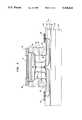
- FIG. 3is a cross-section of a VCSEL with an intra-cavity stratified electrode and current aperture
- FIG. 4is an enlarged cross-section of a lower mirror shown in FIG. 3;
- FIG. 5(a)is an enlarged cross-section of a laser cavity shown in FIG. 3;
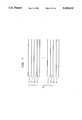
- FIG. 5(b)is an illustration of the standing wave intensity with respect to the vertical positions of the layers in the laser cavity shown in FIG. 5(a);
- FIG. 5(c)is the bandgap diagram of the layers in the stratified electrode of FIG. 3 with respect to their vertical positions in the optical cavity;
- FIG. 5(d)is a modified structure of FIG. 3 utilizing a shallow implantation to reduce contact resistance
- FIG. 5(e)is another modified structure of FIG. 3 utilizing an etched mesa to reduce contact resistance
- FIG. 6is a cross-section of the active region and the upper and low spacers of the laser structure shown in FIG. 3;
- FIG. 7is enlarged cross-section of an upper dielectric DBR mirror shown in FIG. 3;
- FIG. 8is a cross-section of a VCSEL with a stratified electrode and an etch defined electrical current aperture
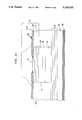
- FIG. 9is a cross-section of a VCSEL having an intra-cavity optical aperture and an optical gain region surrounded by an annular implanted region;
- FIG. 10is a cross-section of a VCSEL with an intra-cavity optical aperture and an etch defined optical gain region
- FIG. 11s a cross-section of a VCSEL with an intra-cavity optical aperture and an optical gain region surrounded by a regrowth material.
- the present inventionrelates to vertical-cavity surface-emitting lasers (VCSELs) having intra-cavity structures.
- the intra-cavity structuresinclude a stratified electrode, a stratified electrode with a current aperture, and/or an optical aperture.
- FIGS. 1-10illustrative views of various VCSEL structures in accordance with principles of the invention are shown. For convenience of reference, in the above figures, like elements have been given the same reference designation.
- FIG. 1Shown in FIG. 1 is a VCSEL with a stratified electrode in accordance with the invention.
- the VCSELcomprises a lower mirror 20, a lower spacer 30, an stratified electrode 60, and an upper mirror 70.
- layers 20, 30, 40, 50are epitaxially formed on a substrate 10.
- First stratified electrode 60is also epitaxially formed on upper spacer 50.
- Two electrical contacts, a top electrical contact 80 for electrically contacting first stratified electrode 60 and a bottom electrical contact 90 for electrically contacting substrate 10,are also constructed.
- First stratified electrode 60comprises two high doped layers 63 and two low doped layers 62, 64.
- Layers 62, 63, and 64have the same conductivity type of dopants as upper spacer 50, so as to conduct electrical current to active region 40.
- a current blocking region 44formed by an annular proton implantation into the active region, is utilized to horizontally confine the electrical current.
- Electrical currentas indicated by solid arrows 100, flows horizontally and then vertically into the active region to cause optical radiation. As illustrated in FIG. 1, due to the high conductivity in the high doped layers, there is substantial lateral current flow in high doped layers 63.
- FIG. 3An embodiment which also utilizes a second stratified electrode is shown in FIG. 3.
- a second stratified electrode 25is disposed between lower spacer 30 and lower mirror 20.
- the second stratified electrodecomprises two high doped layers 24 and two low doped layers 22, 23.
- Layers 22, 23, 24have the same conductivity type dopants as lower spacer 30, but have the opposite conductivity type dopants as first stratified electrode 60.
- An electrical contact 95is constructed and electrically connected to second stratified electrode 25. Alternatively, electrical contact 95 could also be constructed indentically to electrical contact 90 of FIG. 1.
- the series resistance and optical absorption of the VCSELare further reduced by the use of second stratified electrode 25.
- italso allows epitaxially grown semiconductor lower mirror 20 to be undoped, thereby reducing light absorption in the lower mirror.
- a major advantage in utilizing electrical contact 95is that substrate 10 can be made of a semi-insulating material, such as, for example, semi-insulating GaAs.
- Semi-insulating materialssuch as, for example, semi-insulating GaAs.
- Those applications requiring the monolithic integration of VCSELs with other electronic or electro-optical devices to form optoelectronic integrated circuitsgreatly benefit from the use of semi-insulating materials.
- high speed or high frequency applicationswill benefit from the use of a semi-insulating substrate.
- HBTsheterojunction bipolar transistors
- HFETsheterojunction field effect transistors
- HPTsheterojunction phototransistors
- photodetectorsin a manner similar to that disclosed in our co-pending application Ser. No. 07/823,496 entitled “Integration of Transistors With Vertical Cavity Surface Emitting Lasers” filed on Jan. 21, 1992, which is incorporated herein by reference.
- Such integrationis contemplated in the practice of the invention.
- a VCSEL with a stratified electrode and an ion-implanted electrical current apertureis utilized as one means to substantially eliminate higher transverse mode lasing.
- Higher transverse mode lasingis mainly due to two factors: (1) the current often flows at higher density in the outer part of the active layer due to low resistance; and (2) the gain in the central portion of the active layer is quickly bleached by the lowest-order mode and cannot be replenished fast enough due to the lack of good transverse conductivity in the active region.
- a stratified electrode with an intra-cavity current apertureprovides good transverse conductance and uniform current injection into the active region so as to substantially eliminate higher transverse mode lasing.
- the fabrication process of this devicebegins with a n + doped GaAs substrate 10, followed by the sequential epitaxial growth of lower semiconductor DBR mirror 20, lower spacer 30, active region 40, upper spacer 50, and stratified electrode 60.
- Two proton implanted regions, a deep implanted region 48 for defining a current aperture 47, and a shallow implanted region 35 for isolating the device from other devices on the same substrate,are formed by well known implantation techniques.
- the deviceis further thermally annealed at a high temperature to reduce damage caused by the implantation.
- Top ohmic contact 80 for contacting the stratified electrodeis formed by photolithography and metallic deposition.
- Upper dielectric mirror 70is then deposited and defined by photolithography and dielectric deposition.
- Substrate 10is then lapped down to a desired thickness before forming a back ohmic contact 90 for contacting the n + doped GaAs substrate.
- Current aperture 47is defined by annular shaped proton implanted region 48.
- current aperture 47is designed to have a smaller diameter than upper mirror 70.
- the implantation energyis judiciously chosen such that the implanted protons are substantially vertically confined in stratified electrode 60 and upper spacer 50.
- the implantation proton concentrationis chosen such that, in the implanted region, the p-type low doped layers become highly resistive whereas the p + -type high doped layers remain conductive. This configuration confines electrical current 110, as indicated by the solid arrow, to flow vertically and uniformly into the active region, diminishing current crowding at the periphery of the active region and resulting in single transverse mode TEM 00 operation.
- current aperture 47can also be combined with second stratified layer 25 and/or electrical contact 95 of FIG. 2.
- lower mirror 20comprises alternating layers 21, 22 of n + doped AlAs and AlGaAs, respectively. Each layer is a ⁇ /4 thick, where ⁇ is the wavelength of the emitted radiation.
- ⁇is the wavelength of the emitted radiation.
- an optical cavity sandwiched by upper and lower mirrorscomprises lower spacers 30, active region 40, upper spacer 50, and stratified electrode 60.
- Stratified electrode 60comprises p-type high doped AlGaAs layers 63 and low doped InGaP layers 62 and 64.
- high doped layer 63has a thickness equal to or less than ⁇ /4n
- low doped layer 64has a thickness equal to or greater than ⁇ /4n
- the sum of the thickness of layer 63 and layer 64being substantially ⁇ /2n where n is the index of refraction of the respective layers.
- Low doped layer 62has a thickness of ⁇ /8n.
- the p-type doping concentrations of the high and low doped layersare approximately 10 20 /cm 3 and 10 18 /cm 3 , respectively. With such a high doping concentration, high doped layers 63 become very conductive.
- FIG. 5(b)shows the standing wave intensity of the VCSEL with respect to the vertical position in the optical cavity wherein high doped layers 63 are centered at standing wave minima, and low doped layers 64 are centered at standing wave maxima.
- the standing wave intensitycorresponds to the intensity of the light in the optical cavity.
- the standing wave maximaare where the light is most intense, whereas the standing wave minima are where the light is least intense.
- Lightis more readily absorbed by high doped materials and less absorbed by low doped materials.
- by placing the high doped layers at the intensity minima and the low doped layers at the intensity maximalight absorption in stratified electrode 60 is minimized.
- Low doped layer 62 of stratified electrode 60has a thickness of ⁇ /8n so that the interface of the upper mirror and the stratified electrode is located at the standing wave maxima.
- FIG. 5(c)shows a valence band diagram of the layers in stratified electrode 60 with respect to their vertical positions in the laser cavity. Holes 61 from each high doped AlGaAs layer are restricted therein due to the energy barrier present at the AlGaAs/InGaP interface. This results in a higher transverse conductance in the stratified electrode and also prevents the highly concentrated holes in the high doped AlGaAs layers from spilling over to the neighboring areas.
- GaAs and AlGaAs, GaAs and InGaP, AlGaAs and InGaP, or Al x Ga.sub.(1-x) As and Al y Ga.sub.(1-y) As where y is a value greater than x,can be utilized as the high and low doped layers, respectively.
- the use of an intra-cavity stratified electrodeallows a series resistance as low as that in edge emitting laser diodes to be realized without substantially compromising the optical quantum efficiency of the laser.
- the uppermost semiconductor structure in FIG. 5(a)can be modified in order to minimize the contact resistance between the top electrical contact and the stratified electrode which is otherwise compromised by the low doping levle of layer 62. It is not desirable for layer 62 to be highly doped inside the laser cavity since it would increase the absorptive loss.
- one way to minimize such contact resistanceis to form a shallow p-type implanted region 65 just outside the laser cavity under top electrical contact 80. This would increase the p-type carrier concentration under top electrical contact 80 without compromising the optical quality of the cavity. Forming this shallow implanted area can be easily accomplished through standard photolithography and implantation.
- top mirror 70Another way, as shown in FIG. 5(e), is to perform a shallow etch to form a mesa structure consisting of top mirror 70 and the central portion of layer 62. Consquently, top electrical contact 80 is formed on high doped layer 63, thereby reducing the contact resistance. Still another way is to stop the epitaxial growth approximately midway in layer 63 and delete the growth of layer 62. In this case upper mirror 70 must be structured with a high index layer on its bottom in order to produce a cavity resonance at the desired wavelength.
- active region 40comprises three approximately 50 Angstrom thick layers 41 of GaInP separated by two approximately 90 Angstrom thick barrier layers 42 of AlGaInP.
- the active regionis sandwiched by lower spacer 30 and upper spacer 50. Both spacers are undoped AlInP material gradually graded to AlInGaP near the active region.
- upper mirror 70comprises SiO 2 layer 71 and TiO 2 layer 72, each layer being a ⁇ /4n thick where n is the index of refraction.
- Layers 71 and 72form a DBR mirror.
- the relatively large difference in the indices of refraction of SiO 2 and TiO 2 and, in general, dielectric materialspermits fewer layers to be used in forming the upper DBR mirror. Typically, 5 to 6 pairs of these layers are sufficient to provide the high reflectivity needed to achieve lasing in a VCSEL.
- the preferred embodiments described aboveutilize an annular proton implanted region 48 to define current aperture 47.
- a vertical mesa etch followed by a selective lateral etch of the active region and surrounding layerscan also be used to define the current aperture and isolate the device.
- Sidewalls 65 and 66are defined by a vertical mesa etch and a lateral selective etch, respectively.
- the lateral etchWhen a mesa is etched to the level of the active material, it is possible for the lateral etch to include a passivation of sidewall 66 of the active material. This passivation preserves the carrier lifetime, reduces the non-radiative recombination and, therefore, results in a lower threshold current and increased optical quantum efficiency.
- a VCSELcomprises a substrate 200, a lower DBR mirror 210, a lower spacer 220, an active region 230, an upper spacer 240, and an upper DBR mirror 275.
- a metal layer 260 having an optical aperture 265is formed within upper mirror 275, thereby dividing upper mirror 275 into two portions; a lower portion 250 and an upper portion 270.
- This metal layerperferably consisting of gold beryllium (AuBe), also functions as an ohmic contact layer electrically connected to lower portion 250.
- lower portion 250includes only a few pairs of semiconductor DBR layers, resulting in low series resistance. The pairs of semiconductor DBR layers contained in lower portion 250 should be fewer than 10, and the optimum number is dependent on, for example, the specific device geometry, the radiation wavelength ⁇ , and the mirror material.
- upper portion 270can either be a semiconductor DBR mirror as shown in FIG. 4, a dielectric DBR mirror as shown in FIG. 7, or a combination of both. Details relating to the design and construction of the semiconductor DBR mirrors, dielectric DBR mirrors, spacers, and active region are set forth above and will not be discussed in detail here for the sake of clarity.
- An optical gain region 235having a desired diameter, is defined by an annular shaped proton implanted region 245 in active region 230.
- Optical aperture 265is designed to have a diameter smaller than that of the optical gain region and, moreover, is dimensioned so as to restrict the propagation modes of the emitted laser radiation to the TEM 00 mode in accordance with well known laser radiation theory.
- the diameter of optical aperture 265is between 2 to 7 ⁇ m
- the diameter of gain region 235is between 10 to 30 ⁇ m
- the device diameter, dis about 15 ⁇ m larger than the optical gain region.
- FIG. 10shows the device with an optical gain region which is defined by a vertical mesa etch that reveals sidewall 265, followed by a lateral etching of the active region and the surrounding materials that reveal sidewall 266.
- active region sidewall 266can be passivated during or after the lateral etching so as to reduce the non-radiative recombination.
- another means to define the optical gain regionis, after vertically etching down the surrounding region below the active region, to vertically regrow around the optical gain region with a material having a high resistivity and lower index of refraction than that of the active region.
- undoped AlGaAs region 227may be regrown to surround sidewall 225.
- the optical effects of metal layer 260 on the laser cavitycan be tailored by varying its thickness and location. By making metal layer 260 about 100 ⁇ thick or less, its optical absorption can be made small. Furthermore, by placing a thin metal layer such as this in an intensity minimum of standing waves, its optical absorption can be negligibly small. The optical absorption effects of metal layer 260 can thus be continuously tuned by varying its thickness, its location, and the diameter of its aperture.
- the process for constructing the above structurebegins with growing lower mirror 210 on substrate 200, followed by a sequential growth of lower spacer 220, active region 230, upper spacer 240, and first upper mirror portion 250. Then the optical gain region with a desired diameter is defined by etching the surrounding areas vertically down below the active region that results in a mesa structure revealing sidewall 225. Following the etching, AlGaAs is regrown to the same height as the mesa structure so as to form a planar surface. Metal layer 260 is then deposited and optical aperture 265 formed, followed by the deposition of the dielectric layers that form second upper mirror portion 270. Dielectric mirror 270 is then defined and electrical contacts 280 and 290 made to the metal layer and the substrate, respectively.
- the above regrowth structurehas several advantages over the implanted or lateral etched structures.
- the regrowth structureprovides a larger index of refraction step between the active region and the surrounding material than does the implanted structure.
- optical radiationis better confined in the regrowth VCSEL structure than in implanted structure, thereby greatly improving the optical quantum efficiency of the laser and allowing smaller diameter lasers to be made.
- the regrowthplanarizes the VCSEL structure and facilitates electrical contact.
- free standing lasers formed by etchingdue to their small sizes, it is extremely difficult to make electrical contacts to the top portions of the lasers.
- the regrowth structures having a planarized surfaceelectrical contact to the top portion of the laser can easily and reliably be made.
- regrowthcan passivate sidewall damage produced by etching and thus can terminate dangling bonds and quench non-radiative recombination.
- a single stratified electrodecan be placed between the lower mirror and the lower spacer in the VCSEL, or the regrowth AlGaAs regions may be replaced with dielectric materials having a lower index of refraction than that of the active region material.
- upper mirror 70 of FIGS. 1, 2, 3 and 8can be divided into upper and lower portions, above and below stratified electrode, respectively, analogously to the division of upper mirror 275 in FIGS. 9, 10 and 11.
Landscapes
- Physics & Mathematics (AREA)
- Condensed Matter Physics & Semiconductors (AREA)
- General Physics & Mathematics (AREA)
- Electromagnetism (AREA)
- Optics & Photonics (AREA)
- Semiconductor Lasers (AREA)
Abstract
Description
Claims (38)
Priority Applications (9)
| Application Number | Priority Date | Filing Date | Title |
|---|---|---|---|
| US07/879,471US5245622A (en) | 1992-05-07 | 1992-05-07 | Vertical-cavity surface-emitting lasers with intra-cavity structures |
| EP98115197AEP0898347A1 (en) | 1992-05-07 | 1993-05-06 | Vertical-cavity surface-emitting lasers with intra-cavity structures |
| PCT/US1993/004293WO1993022813A1 (en) | 1992-05-07 | 1993-05-06 | Vertical-cavity surface-emitting lasers with intra-cavity structures |
| AU42369/93AAU4236993A (en) | 1992-05-07 | 1993-05-06 | Vertical-cavity surface-emitting lasers with intra-cavity structures |
| CA002135182ACA2135182A1 (en) | 1992-05-07 | 1993-05-06 | Vertical-cavity surface-emitting lasers with intra-cavity structures |
| EP93911113AEP0663112B1 (en) | 1992-05-07 | 1993-05-06 | Vertical-cavity surface-emitting lasers with intra-cavity structures |
| JP5519633AJPH07507183A (en) | 1992-05-07 | 1993-05-06 | Vertical cavity surface emitting laser with internal cavity structure |
| DE69323433TDE69323433T2 (en) | 1992-05-07 | 1993-05-06 | SURFACE-EMITTING LASER WITH VERTICAL RESONATOR AND STRUCTURES CONTAINING IT |
| CN93106745ACN1081541A (en) | 1992-05-07 | 1993-05-07 | Vertical-cavity surface emitting laser with mucosal structure |
Applications Claiming Priority (1)
| Application Number | Priority Date | Filing Date | Title |
|---|---|---|---|
| US07/879,471US5245622A (en) | 1992-05-07 | 1992-05-07 | Vertical-cavity surface-emitting lasers with intra-cavity structures |
Publications (1)
| Publication Number | Publication Date |
|---|---|
| US5245622Atrue US5245622A (en) | 1993-09-14 |
Family
ID=25374226
Family Applications (1)
| Application Number | Title | Priority Date | Filing Date |
|---|---|---|---|
| US07/879,471Expired - LifetimeUS5245622A (en) | 1992-05-07 | 1992-05-07 | Vertical-cavity surface-emitting lasers with intra-cavity structures |
Country Status (8)
| Country | Link |
|---|---|
| US (1) | US5245622A (en) |
| EP (2) | EP0898347A1 (en) |
| JP (1) | JPH07507183A (en) |
| CN (1) | CN1081541A (en) |
| AU (1) | AU4236993A (en) |
| CA (1) | CA2135182A1 (en) |
| DE (1) | DE69323433T2 (en) |
| WO (1) | WO1993022813A1 (en) |
Cited By (149)
| Publication number | Priority date | Publication date | Assignee | Title |
|---|---|---|---|---|
| US5337327A (en)* | 1993-02-22 | 1994-08-09 | Motorola, Inc. | VCSEL with lateral index guide |
| US5341390A (en)* | 1992-04-16 | 1994-08-23 | Hewlett-Packard Company | Surface emitting second harmonic generating device |
| US5343487A (en)* | 1992-10-01 | 1994-08-30 | Optical Concepts, Inc. | Electrical pumping scheme for vertical-cavity surface-emitting lasers |
| US5351256A (en)* | 1993-04-28 | 1994-09-27 | The United States Of America As Represented By The United States Department Of Energy | Electrically injected visible vertical cavity surface emitting laser diodes |
| US5351257A (en)* | 1993-03-08 | 1994-09-27 | Motorola, Inc. | VCSEL with vertical offset operating region providing a lateral waveguide and current limiting and method of fabrication |
| US5359618A (en)* | 1993-06-01 | 1994-10-25 | Motorola, Inc. | High efficiency VCSEL and method of fabrication |
| US5404370A (en)* | 1993-04-30 | 1995-04-04 | Fujitsu Limited | Planar light emitting device having a reduced optical loss |
| US5412680A (en)* | 1994-03-18 | 1995-05-02 | Photonics Research Incorporated | Linear polarization of semiconductor laser |
| US5416044A (en)* | 1993-03-12 | 1995-05-16 | Matsushita Electric Industrial Co., Ltd. | Method for producing a surface-emitting laser |
| US5459746A (en)* | 1992-09-29 | 1995-10-17 | Kabushiki Kaisha Toshiba | Surface emission type semiconductor light-emitting device |
| US5557626A (en)* | 1994-06-15 | 1996-09-17 | Motorola | Patterned mirror VCSEL with adjustable selective etch region |
| US5563900A (en)* | 1994-08-09 | 1996-10-08 | Motorola | Broad spectrum surface-emitting led |
| US5596595A (en)* | 1995-06-08 | 1997-01-21 | Hewlett-Packard Company | Current and heat spreading transparent layers for surface-emitting lasers |
| EP0782229A1 (en)* | 1995-12-27 | 1997-07-02 | Alcatel | Semiconductor surface emitting laser |
| US5677924A (en)* | 1994-11-14 | 1997-10-14 | Sharp Kabushiki Kaisha | Resonant-cavity optical device |
| US5699375A (en)* | 1996-07-08 | 1997-12-16 | Xerox Corporation | Multiple wavelength, surface emitting laser with broad bandwidth distributed Bragg reflectors |
| WO1998000895A1 (en)* | 1996-06-28 | 1998-01-08 | Honeywell Inc. | Current confinement for a vertical cavity surface emitting laser |
| US5729566A (en)* | 1996-06-07 | 1998-03-17 | Picolight Incorporated | Light emitting device having an electrical contact through a layer containing oxidized material |
| US5745515A (en)* | 1996-07-18 | 1998-04-28 | Honeywell Inc. | Self-limiting intrinsically eye-safe laser utilizing an increasing absorption layer |
| US5774487A (en)* | 1996-10-16 | 1998-06-30 | Honeywell Inc. | Filamented multi-wavelength vertical-cavity surface emitting laser |
| US5778018A (en)* | 1994-10-13 | 1998-07-07 | Nec Corporation | VCSELs (vertical-cavity surface emitting lasers) and VCSEL-based devices |
| US5799030A (en)* | 1996-07-26 | 1998-08-25 | Honeywell Inc. | Semiconductor device with a laser and a photodetector in a common container |
| WO1998039824A1 (en)* | 1997-03-06 | 1998-09-11 | Honeywell Inc. | Laser with a selectively changed current confining layer |
| NL1005570C2 (en)* | 1997-03-19 | 1998-09-22 | Univ Eindhoven Tech | Vertical contact surface emitting laser manufacture |
| US5812581A (en)* | 1996-07-26 | 1998-09-22 | Honeywell Inc. | Lens for a semiconductive device with a laser and a photodetector in a common container |
| US5818863A (en)* | 1996-01-30 | 1998-10-06 | France Telecom | Laser-emitting component having an injection zone of limited width |
| US5831960A (en)* | 1997-07-17 | 1998-11-03 | Motorola, Inc. | Integrated vertical cavity surface emitting laser pair for high density data storage and method of fabrication |
| US5940422A (en)* | 1996-06-28 | 1999-08-17 | Honeywell Inc. | Laser with an improved mode control |
| US5949808A (en)* | 1995-07-21 | 1999-09-07 | Matsushita Electric Industrial Co., Ltd. | Semiconductor laser and method for producing the same |
| US5978401A (en)* | 1995-10-25 | 1999-11-02 | Honeywell Inc. | Monolithic vertical cavity surface emitting laser and resonant cavity photodetector transceiver |
| US5985686A (en)* | 1996-08-21 | 1999-11-16 | W. L. Gore & Associates, Inc. | Process for manufacturing vertical cavity surface emitting lasers using patterned wafer fusion and the device manufactured by the process |
| US6021146A (en)* | 1997-09-15 | 2000-02-01 | Motorola, Inc. | Vertical cavity surface emitting laser for high power single mode operation and method of fabrication |
| US6075802A (en)* | 1998-03-12 | 2000-06-13 | Telefonaktiebolaget L, Ericsson | Lateral confinement laser |
| US6117699A (en)* | 1998-04-10 | 2000-09-12 | Hewlett-Packard Company | Monolithic multiple wavelength VCSEL array |
| EP1035621A1 (en)* | 1999-02-11 | 2000-09-13 | CSEM Centre Suisse d'Electronique et de Microtechnique S.A. - Recherche et Développement | A semiconductor laser device and method for fabrication thereof |
| WO2000052794A3 (en)* | 1999-02-26 | 2000-12-28 | Infineon Technologies Ag | Vertical resonator laser diode with a small aperture opening |
| WO2001009995A1 (en)* | 1999-07-30 | 2001-02-08 | Coretek, Inc. | Single mode operation of microelectromechanically tunable, half-symmetric, vertical cavity surface emitting lasers |
| WO2001095443A1 (en)* | 1999-06-02 | 2001-12-13 | Cielo Communications, Inc. | Single mode vertical cavity surface emitting laser |
| US6343090B1 (en) | 1997-11-29 | 2002-01-29 | Electronics And Telecommunications Research Institute | Single mode surface emitting laser |
| WO2002017449A1 (en)* | 2000-08-22 | 2002-02-28 | The Regents Of The University Of California | Double intracavity contacted long-wavelength vcsels |
| US20020085610A1 (en)* | 2000-12-29 | 2002-07-04 | Morgan Robert A. | Spatially modulated reflector for an optoelectronic device |
| US20020106160A1 (en)* | 2000-12-29 | 2002-08-08 | Honeywell International Inc. | Resonant reflector for increased wavelength and polarization control |
| US20020172247A1 (en)* | 2001-04-05 | 2002-11-21 | Avalon Photonics, Ltd. | Vertical-cavity surface-emitting laser with enhanced transverse mode stability and polarization stable single mode output |
| US6493368B1 (en) | 1999-07-21 | 2002-12-10 | Agere Systems Inc. | Lateral injection vertical cavity surface-emitting laser |
| US20020186735A1 (en)* | 1995-12-18 | 2002-12-12 | Jack Jewell | Conductive element with lateral oxidation barrier |
| US6515305B2 (en) | 2000-09-18 | 2003-02-04 | Regents Of The University Of Minnesota | Vertical cavity surface emitting laser with single mode confinement |
| US20030031221A1 (en)* | 2000-04-05 | 2003-02-13 | Coretek, Inc. | Single mode operation of microelectromechanically tunable, half-symmetric, vertical cavity surface emitting lasers |
| US6529541B1 (en)* | 2000-11-13 | 2003-03-04 | Fuji Xerox Co., Ltd. | Surface emitting semiconductor laser |
| US6534331B2 (en)* | 2001-07-24 | 2003-03-18 | Luxnet Corporation | Method for making a vertical-cavity surface emitting laser with improved current confinement |
| US6542527B1 (en) | 1998-08-27 | 2003-04-01 | Regents Of The University Of Minnesota | Vertical cavity surface emitting laser |
| US20030076864A1 (en)* | 2001-10-23 | 2003-04-24 | Hironobu Sai | Surface light emitting type semiconductor laser having a vertical cavity |
| US6556349B2 (en) | 2000-12-27 | 2003-04-29 | Honeywell International Inc. | Variable focal length micro lens array field curvature corrector |
| US6577658B1 (en) | 1999-09-20 | 2003-06-10 | E20 Corporation, Inc. | Method and apparatus for planar index guided vertical cavity surface emitting lasers |
| US20030123502A1 (en)* | 2001-12-28 | 2003-07-03 | Biard James R. | Gain guide implant in oxide vertical cavity surface emitting laser |
| US20030133483A1 (en)* | 1997-12-12 | 2003-07-17 | Honeywell Inc. | VCSEL structure insensitive to mobile hydrogen |
| US6606199B2 (en) | 2001-10-10 | 2003-08-12 | Honeywell International Inc. | Graded thickness optical element and method of manufacture therefor |
| WO2002045217A3 (en)* | 2000-11-28 | 2003-08-14 | Honeywell Int Inc | Versatile method and system for single mode vcsels |
| US20030156610A1 (en)* | 2002-02-21 | 2003-08-21 | Hoki Kwon | Carbon doped GaAsSb suitable for use in tunnel junctions of long-wavelength VCSELs |
| US20030156611A1 (en)* | 2002-02-21 | 2003-08-21 | Hoki Kwon | GaAs/Al(Ga)As distributed bragg reflector on InP |
| US6618414B1 (en)* | 2002-03-25 | 2003-09-09 | Optical Communication Products, Inc. | Hybrid vertical cavity laser with buried interface |
| US20030185267A1 (en)* | 2002-03-28 | 2003-10-02 | Applied Optoelectronics, Inc. | VCSEL with antiguide current confinement layer |
| US6631154B2 (en) | 2000-08-22 | 2003-10-07 | The Regents Of The University Of California | Method of fabricating a distributed Bragg reflector having enhanced thermal and electrical properties |
| US6650683B2 (en)* | 2000-11-20 | 2003-11-18 | Fuji Xerox Co, Ltd. | Surface emitting semiconductor laser |
| US20030219917A1 (en)* | 1998-12-21 | 2003-11-27 | Johnson Ralph H. | System and method using migration enhanced epitaxy for flattening active layers and the mechanical stabilization of quantum wells associated with vertical cavity surface emitting lasers |
| US20030235226A1 (en)* | 2002-06-20 | 2003-12-25 | Fuji Xerox Co., Ltd. | Surface emitting semiconductor laser and method of fabricating the same |
| US6671304B2 (en) | 2001-08-28 | 2003-12-30 | The United States Of America As Represented By The Secretary Of The Navy | Amplitude-modulated laser for high-bandwidth communications systems |
| US20040032892A1 (en)* | 2001-02-08 | 2004-02-19 | Jurgen Muller | Semiconductor laser |
| US6697405B2 (en)* | 2000-12-15 | 2004-02-24 | Hitachi, Ltd. | Vertical cavity surface emitting lasers, optical modules and systems |
| WO2003058772A3 (en)* | 2001-12-28 | 2004-02-26 | Honeywell Int Inc | Current confinement, capacitance reduction and isolation of vcsels using deep elemental traps |
| US20040036078A1 (en)* | 2002-06-20 | 2004-02-26 | Seiko Epson Corporation | Semiconductor device, method of manufacturing the same, electro-optic device and electronic apparatus |
| US20040081215A1 (en)* | 2002-10-28 | 2004-04-29 | Honeywell International Inc. | Distributed bragg reflector for optoelectronic device |
| US20040101009A1 (en)* | 2002-11-21 | 2004-05-27 | Honeywell International Inc. | Long wavelength VCSEL with tunnel junction, and implant |
| US6751245B1 (en) | 1999-06-02 | 2004-06-15 | Optical Communication Products, Inc. | Single mode vertical cavity surface emitting laser |
| US6754245B2 (en)* | 2001-02-02 | 2004-06-22 | Samsung Electro-Mechanics Co., Ltd. | GaN series surface-emitting laser diode having spacer for effective diffusion of holes between p-type electrode and active layer, and method for manufacturing the same |
| US20040121551A1 (en)* | 2002-12-20 | 2004-06-24 | Tzu-Yu Wang | Angled wafer rotating ion implantation |
| US6768756B2 (en)* | 2001-03-12 | 2004-07-27 | Axsun Technologies, Inc. | MEMS membrane with integral mirror/lens |
| WO2004034525A3 (en)* | 2002-10-11 | 2004-07-29 | Ziva Corp | Current-controlled polarization switching vertical cavity surface emitting laser |
| US6782027B2 (en) | 2000-12-29 | 2004-08-24 | Finisar Corporation | Resonant reflector for use with optoelectronic devices |
| US20040208216A1 (en)* | 2001-04-11 | 2004-10-21 | Naone Ryan Likeke | Long wavelength vertical cavity surface emitting laser |
| US6810065B1 (en) | 2000-11-28 | 2004-10-26 | Optical Communication Productions, Inc. | Low electrical resistance n-type mirror for optoelectronic devices |
| US6810064B1 (en) | 2000-08-22 | 2004-10-26 | The Regents Of The University Of California | Heat spreading layers for vertical cavity surface emitting lasers |
| US20040222363A1 (en)* | 2003-05-07 | 2004-11-11 | Honeywell International Inc. | Connectorized optical component misalignment detection system |
| US20040264536A1 (en)* | 2003-06-27 | 2004-12-30 | Honeywell International Inc. | Dielectric VCSEL gain guide |
| US20050014390A1 (en)* | 2003-07-18 | 2005-01-20 | Honeywell International Inc. | Edge bead control method and apparatus |
| US20050013542A1 (en)* | 2003-07-16 | 2005-01-20 | Honeywell International Inc. | Coupler having reduction of reflections to light source |
| US20050013539A1 (en)* | 2003-07-17 | 2005-01-20 | Honeywell International Inc. | Optical coupling system |
| US20050019973A1 (en)* | 2003-07-23 | 2005-01-27 | Palo Alto Research Center, Incorporated | Phase array oxide-confined VCSEL |
| US20050031011A1 (en)* | 2000-11-28 | 2005-02-10 | Biard James R. | Electron affinity engineered VCSELs |
| US20050036533A1 (en)* | 2000-12-29 | 2005-02-17 | Honeywell To Finisar | Tunable detector |
| US20050074045A1 (en)* | 2003-10-07 | 2005-04-07 | Yi-Tsuo Wu | VCSEL and the fabrication method of the same |
| US20050092710A1 (en)* | 2003-10-29 | 2005-05-05 | Biard James R. | Long wavelength VCSEL device processing |
| US6906353B1 (en) | 2003-11-17 | 2005-06-14 | Jds Uniphase Corporation | High speed implanted VCSEL |
| US20050129078A1 (en)* | 1998-12-21 | 2005-06-16 | Johnson Ralph H. | Multicomponent barrier layers in quantum well active regions to enhance confinement and speed |
| US6909554B2 (en) | 2000-12-27 | 2005-06-21 | Finisar Corporation | Wafer integration of micro-optics |
| US20050147142A1 (en)* | 2003-11-18 | 2005-07-07 | Seiko Epson Corporation | Surface-emitting type semiconductor laser and method of manufacturing the same |
| US20050158902A1 (en)* | 1997-02-07 | 2005-07-21 | Xerox Corporation | Method and structure for eliminating polarization instability in laterally - oxidized VCSELs |
| US20050157765A1 (en)* | 1998-12-21 | 2005-07-21 | Honeywell International Inc. | Low temperature grown layers with migration enhanced epitaxy adjacent to an InGaAsN(Sb) based active region |
| US6922426B2 (en) | 2001-12-20 | 2005-07-26 | Finisar Corporation | Vertical cavity surface emitting laser including indium in the active region |
| US6961489B2 (en) | 2003-06-30 | 2005-11-01 | Finisar Corporation | High speed optical system |
| US6965626B2 (en) | 2002-09-03 | 2005-11-15 | Finisar Corporation | Single mode VCSEL |
| US6975660B2 (en) | 2001-12-27 | 2005-12-13 | Finisar Corporation | Vertical cavity surface emitting laser including indium and antimony in the active region |
| US20060045162A1 (en)* | 2004-08-31 | 2006-03-02 | Finisar Corporation | Distributed bragg reflector for optoelectronic device |
| US20060056762A1 (en)* | 2003-07-02 | 2006-03-16 | Honeywell International Inc. | Lens optical coupler |
| US20060072639A1 (en)* | 2004-10-01 | 2006-04-06 | Johnson Ralph H | Vertical cavity surface emitting laser with undoped top mirror |
| US20060072640A1 (en)* | 2004-10-01 | 2006-04-06 | Johnson Ralph H | Vertical cavity surface emitting laser having multiple top-side contacts |
| US20060098706A1 (en)* | 2004-11-09 | 2006-05-11 | Seiko Epson Corporation | Surface-emitting type semiconductor laser |
| US7054345B2 (en) | 2003-06-27 | 2006-05-30 | Finisar Corporation | Enhanced lateral oxidation |
| US7058112B2 (en) | 2001-12-27 | 2006-06-06 | Finisar Corporation | Indium free vertical cavity surface emitting laser |
| US7075962B2 (en) | 2003-06-27 | 2006-07-11 | Finisar Corporation | VCSEL having thermal management |
| US7095767B1 (en)* | 1999-08-30 | 2006-08-22 | Research Investment Network, Inc. | Near field optical apparatus |
| US7095770B2 (en) | 2001-12-20 | 2006-08-22 | Finisar Corporation | Vertical cavity surface emitting laser including indium, antimony and nitrogen in the active region |
| US20060246700A1 (en)* | 1998-12-21 | 2006-11-02 | Johnson Ralph H | Migration enhanced epitaxy fabrication of active regions having quantum wells |
| US20060268954A1 (en)* | 2004-08-31 | 2006-11-30 | Johnson Ralph H | Light emitting semiconductor device having an electrical confinement barrier near the active region |
| WO2006011936A3 (en)* | 2004-06-30 | 2006-12-07 | Cree Inc | Light emitting devices having current blocking structures and methods of fabricating light emitting devices having current blocking structures |
| US7149383B2 (en) | 2003-06-30 | 2006-12-12 | Finisar Corporation | Optical system with reduced back reflection |
| US7167495B2 (en) | 1998-12-21 | 2007-01-23 | Finisar Corporation | Use of GaAs extended barrier layers between active regions containing nitrogen and AlGaAs confining layers |
| US7210857B2 (en) | 2003-07-16 | 2007-05-01 | Finisar Corporation | Optical coupling system |
| US20070127536A1 (en)* | 2004-10-01 | 2007-06-07 | Finisar Corporation | Semiconductor having enhanced carbon doping |
| US20070147458A1 (en)* | 2005-06-10 | 2007-06-28 | Novalux, Inc. | Cavity and packaging designs for arrays of vertical cavity surface emitting lasers with or without extended cavities |
| EP1808911A1 (en)* | 2006-01-13 | 2007-07-18 | Interuniversitair Microelektronica Centrum | Organic light-emitting device with field-effect enhanced mobility |
| US7283697B1 (en) | 2006-10-03 | 2007-10-16 | Motorola, Inc. | Point to strip optical communication system |
| US20070254393A1 (en)* | 2004-10-01 | 2007-11-01 | Finisar Corporation | Passivation of vcsel sidewalls |
| US7298942B2 (en) | 2003-06-06 | 2007-11-20 | Finisar Corporation | Pluggable optical optic system having a lens fiber stop |
| US7302127B1 (en) | 2006-10-03 | 2007-11-27 | Motorola, Inc. | Strip to point optical communication system |
| US20080023688A1 (en)* | 2006-07-31 | 2008-01-31 | Finisar Corporation | Efficient carrier injection in a semiconductor device |
| US20080061311A1 (en)* | 2005-01-24 | 2008-03-13 | Cree, Inc. | Led with current confinement structure and surface roughening |
| US20080138079A1 (en)* | 2006-12-06 | 2008-06-12 | Motorola, Inc. | Optical communication system with light guide having variable slidable point of entry or exit |
| US20080138078A1 (en)* | 2006-12-06 | 2008-06-12 | Motorola, Inc. | Point to point optical communication system for conveying signals between multiple housings of a device |
| US7408964B2 (en) | 2001-12-20 | 2008-08-05 | Finisar Corporation | Vertical cavity surface emitting laser including indium and nitrogen in the active region |
| US20080205465A1 (en)* | 2007-02-23 | 2008-08-28 | Cosemi Technologies | Vertical cavity surface emitting laser (vcsel) and related method |
| US20080230794A1 (en)* | 2004-03-08 | 2008-09-25 | Takaki Yasuda | Pn Junction Type Group III Nitride Semiconductor Light-Emitting Device |
| US7433381B2 (en) | 2003-06-25 | 2008-10-07 | Finisar Corporation | InP based long wavelength VCSEL |
| US20080298416A1 (en)* | 2007-06-01 | 2008-12-04 | Jds Uniphase Corporation | Mesa Vertical-Cavity Surface-Emitting Laser |
| US20090080487A1 (en)* | 2007-08-31 | 2009-03-26 | Yutaka Onishi | Vertical cavity surface emitting laser diode (VCSEL) with enhanced emitting efficiency |
| US20090305447A1 (en)* | 2008-06-06 | 2009-12-10 | Finisar Corporation | Implanted vertical cavity surface emitting laser |
| GB2462701A (en)* | 2008-07-22 | 2010-02-24 | Avago Technologies Fiber Ip | Current confining semiconductor light emission divice |
| EP1841026A3 (en)* | 2005-12-19 | 2010-05-12 | Emcore Corporation | Method of fabricating single mode vcsel for optical mouse |
| US7795623B2 (en) | 2004-06-30 | 2010-09-14 | Cree, Inc. | Light emitting devices having current reducing structures and methods of forming light emitting devices having current reducing structures |
| US8031752B1 (en) | 2007-04-16 | 2011-10-04 | Finisar Corporation | VCSEL optimized for high speed data |
| US20110261852A1 (en)* | 2008-12-10 | 2011-10-27 | Furukawa Electric Co., Ltd | Semiconductor laser element and manufacturing method thereof |
| US20120037228A1 (en)* | 2010-08-10 | 2012-02-16 | Du Pont Apollo Limited | Thin-Film Photovoltaic Cell Having Distributed Bragg Reflector |
| US20130215922A1 (en)* | 2010-10-04 | 2013-08-22 | Furukawa Electric Co., Ltd. | Electronic device, surface emitting laser, surface emitting laser array, light source, optical module |
| US9014231B2 (en) | 2012-02-02 | 2015-04-21 | The Board Of Trustees Of The Leland Stanford Junior University | Vertical cavity surface emitting laser nanoscope for near-field applications |
| US20150180212A1 (en)* | 2013-12-20 | 2015-06-25 | Seiko Epson Corporation | Vertical cavity surface emitting laser and atomic oscillator |
| RU2611555C1 (en)* | 2015-12-17 | 2017-02-28 | Федеральное государственное бюджетное учреждение науки Физико-технический институт им. А.Ф. Иоффе Российской академии наук | Semiconductor vertically-emitting laser with intracavity contacts |
| US10333276B2 (en) | 2015-10-08 | 2019-06-25 | International Business Machines Corporation | Vertical microcavity with confinement region having sub-wavelength structures to create an effective refractive index variation |
| CN110970797A (en)* | 2018-10-01 | 2020-04-07 | 迈络思科技有限公司 | High-speed high-bandwidth vertical cavity surface emitting laser |
| US20210028603A1 (en)* | 2018-04-04 | 2021-01-28 | Lg Innotek Co., Ltd. | A surface-emitting laser device and light emitting device including the same |
| WO2021194905A1 (en) | 2020-03-25 | 2021-09-30 | Array Photonics, Inc. | Intracavity contact vcsel structure and method for forming the same |
Families Citing this family (12)
| Publication number | Priority date | Publication date | Assignee | Title |
|---|---|---|---|---|
| DE69931097T2 (en) | 1998-02-25 | 2006-10-19 | Nippon Telegraph And Telephone Corp. | Surface emitting semiconductor laser with vertical resonator |
| US6810062B2 (en) | 2001-04-11 | 2004-10-26 | Axsun Technologies, Inc. | Passive optical resonator with mirror structure suppressing higher order transverse spatial modes |
| JP2005093634A (en)* | 2003-09-17 | 2005-04-07 | Ricoh Co Ltd | Surface emitting semiconductor laser and manufacturing method thereof |
| US8457170B2 (en)* | 2009-08-10 | 2013-06-04 | Koninklijke Philips Electronics N.V. | Vertical cavity surface emitting laser with active carrier confinement |
| JP2011228576A (en)* | 2010-04-22 | 2011-11-10 | Furukawa Electric Co Ltd:The | Semiconductor laser device |
| JP7367484B2 (en)* | 2019-11-22 | 2023-10-24 | 株式会社リコー | Surface-emitting laser elements, surface-emitting lasers, surface-emitting laser devices, light source devices, and detection devices |
| JP7742724B2 (en)* | 2021-06-07 | 2025-09-22 | スタンレー電気株式会社 | Vertical cavity light emitting device and its manufacturing method |
| WO2023171150A1 (en)* | 2022-03-11 | 2023-09-14 | ソニーセミコンダクタソリューションズ株式会社 | Vertical resonator surface emission laser |
| WO2024014140A1 (en)* | 2022-07-14 | 2024-01-18 | ソニーセミコンダクタソリューションズ株式会社 | Surface emitting laser and method for manufacturing surface emitting laser |
| CN115425519A (en)* | 2022-09-30 | 2022-12-02 | 常州纵慧芯光半导体科技有限公司 | A vertical cavity surface emitting laser and its manufacturing method |
| CN118380858A (en)* | 2023-12-08 | 2024-07-23 | 常州纵慧芯光半导体科技有限公司 | Anti-reflection vertical cavity surface emitting laser and chip |
| CN117712830B (en)* | 2024-02-05 | 2024-04-30 | 南昌凯迅光电股份有限公司 | Vertical cavity surface emitting laser and manufacturing method thereof |
Citations (14)
| Publication number | Priority date | Publication date | Assignee | Title |
|---|---|---|---|---|
| US4873696A (en)* | 1988-10-31 | 1989-10-10 | The Regents Of The University Of California | Surface-emitting lasers with periodic gain and a parallel driven nipi structure |
| US4901327A (en)* | 1988-10-24 | 1990-02-13 | General Dynamics Corporation, Electronics Division | Transverse injection surface emitting laser |
| US4943970A (en)* | 1988-10-24 | 1990-07-24 | General Dynamics Corporation, Electronics Division | Surface emitting laser |
| US4949351A (en)* | 1988-04-15 | 1990-08-14 | Omron Tateisi Electronics Co. | Surface-emitting semiconductor laser and manufacturing method of same |
| US4949350A (en)* | 1989-07-17 | 1990-08-14 | Bell Communications Research, Inc. | Surface emitting semiconductor laser |
| US4991179A (en)* | 1989-04-26 | 1991-02-05 | At&T Bell Laboratories | Electrically pumped vertical cavity laser |
| US4999842A (en)* | 1989-03-01 | 1991-03-12 | At&T Bell Laboratories | Quantum well vertical cavity laser |
| US5034958A (en)* | 1990-04-19 | 1991-07-23 | Bell Communications Research, Inc. | Front-surface emitting diode laser |
| US5034344A (en)* | 1989-07-17 | 1991-07-23 | Bell Communications Research, Inc. | Method of making a surface emitting semiconductor laser |
| US5052016A (en)* | 1990-05-18 | 1991-09-24 | University Of New Mexico | Resonant-periodic-gain distributed-feedback surface-emitting semiconductor laser |
| US5056098A (en)* | 1990-07-05 | 1991-10-08 | At&T Bell Laboratories | Vertical cavity laser with mirror having controllable reflectivity |
| US5063569A (en)* | 1990-12-19 | 1991-11-05 | At&T Bell Laboratories | Vertical-cavity surface-emitting laser with non-epitaxial multilayered dielectric reflectors located on both surfaces |
| US5115441A (en)* | 1991-01-03 | 1992-05-19 | At&T Bell Laboratories | Vertical cavity surface emmitting lasers with transparent electrodes |
| US5115442A (en)* | 1990-04-13 | 1992-05-19 | At&T Bell Laboratories | Top-emitting surface emitting laser structures |
Family Cites Families (2)
| Publication number | Priority date | Publication date | Assignee | Title |
|---|---|---|---|---|
| US5181219A (en)* | 1990-09-12 | 1993-01-19 | Seiko Epson Corporation | Surface emission type semiconductor laser |
| US5258990A (en)* | 1991-11-07 | 1993-11-02 | The United States Of America As Represented By The Secretary Of The United States Department Of Energy | Visible light surface emitting semiconductor laser |
- 1992
- 1992-05-07USUS07/879,471patent/US5245622A/ennot_activeExpired - Lifetime
- 1993
- 1993-05-06JPJP5519633Apatent/JPH07507183A/enactivePending
- 1993-05-06DEDE69323433Tpatent/DE69323433T2/ennot_activeExpired - Fee Related
- 1993-05-06CACA002135182Apatent/CA2135182A1/ennot_activeAbandoned
- 1993-05-06EPEP98115197Apatent/EP0898347A1/ennot_activeWithdrawn
- 1993-05-06WOPCT/US1993/004293patent/WO1993022813A1/enactiveIP Right Grant
- 1993-05-06AUAU42369/93Apatent/AU4236993A/ennot_activeAbandoned
- 1993-05-06EPEP93911113Apatent/EP0663112B1/ennot_activeExpired - Lifetime
- 1993-05-07CNCN93106745Apatent/CN1081541A/enactivePending
Patent Citations (14)
| Publication number | Priority date | Publication date | Assignee | Title |
|---|---|---|---|---|
| US4949351A (en)* | 1988-04-15 | 1990-08-14 | Omron Tateisi Electronics Co. | Surface-emitting semiconductor laser and manufacturing method of same |
| US4901327A (en)* | 1988-10-24 | 1990-02-13 | General Dynamics Corporation, Electronics Division | Transverse injection surface emitting laser |
| US4943970A (en)* | 1988-10-24 | 1990-07-24 | General Dynamics Corporation, Electronics Division | Surface emitting laser |
| US4873696A (en)* | 1988-10-31 | 1989-10-10 | The Regents Of The University Of California | Surface-emitting lasers with periodic gain and a parallel driven nipi structure |
| US4999842A (en)* | 1989-03-01 | 1991-03-12 | At&T Bell Laboratories | Quantum well vertical cavity laser |
| US4991179A (en)* | 1989-04-26 | 1991-02-05 | At&T Bell Laboratories | Electrically pumped vertical cavity laser |
| US4949350A (en)* | 1989-07-17 | 1990-08-14 | Bell Communications Research, Inc. | Surface emitting semiconductor laser |
| US5034344A (en)* | 1989-07-17 | 1991-07-23 | Bell Communications Research, Inc. | Method of making a surface emitting semiconductor laser |
| US5115442A (en)* | 1990-04-13 | 1992-05-19 | At&T Bell Laboratories | Top-emitting surface emitting laser structures |
| US5034958A (en)* | 1990-04-19 | 1991-07-23 | Bell Communications Research, Inc. | Front-surface emitting diode laser |
| US5052016A (en)* | 1990-05-18 | 1991-09-24 | University Of New Mexico | Resonant-periodic-gain distributed-feedback surface-emitting semiconductor laser |
| US5056098A (en)* | 1990-07-05 | 1991-10-08 | At&T Bell Laboratories | Vertical cavity laser with mirror having controllable reflectivity |
| US5063569A (en)* | 1990-12-19 | 1991-11-05 | At&T Bell Laboratories | Vertical-cavity surface-emitting laser with non-epitaxial multilayered dielectric reflectors located on both surfaces |
| US5115441A (en)* | 1991-01-03 | 1992-05-19 | At&T Bell Laboratories | Vertical cavity surface emmitting lasers with transparent electrodes |
Non-Patent Citations (14)
| Title |
|---|
| Hasnain et al., "Continuous Wave Top Surface Emitting Quantum Well Lasers Using Hybrid Metal/Semiconductor Reflectors," Electronic Letters, vol. 26, Sep., 1990, pp. 1590-1592. |
| Hasnain et al., "High Temperature and High Frequency Performance of Gain-Guided Surface Emitting Lasers," Electronic Letters, vol. 27, No. 11, May 1991, pp. 915-916. |
| Hasnain et al., Continuous Wave Top Surface Emitting Quantum Well Lasers Using Hybrid Metal/Semiconductor Reflectors, Electronic Letters , vol. 26, Sep., 1990, pp. 1590 1592.* |
| Hasnain et al., High Temperature and High Frequency Performance of Gain Guided Surface Emitting Lasers, Electronic Letters , vol. 27, No. 11, May 1991, pp. 915 916.* |
| Jewell et al., "Microlasers," Scientific American, vol. 265, No. 5, Nov., 1991, pp. 86-96. |
| Jewell et al., "Vertical Cavity Single Quantum Well Laser", Appl. Phys. Lett., vol. 55, Jul., 1989, pp. 424-426. |
| Jewell et al., "Vertical-Cavity Surface Emitting Lasers: Design Growth, Fabrication, Characterization," IEEE Journal of Quantum Electronics, vol. 27, No. 6, Jun. 1991, pp. 1332-1346. |
| Jewell et al., Microlasers, Scientific American , vol. 265, No. 5, Nov., 1991, pp. 86 96.* |
| Jewell et al., Vertical Cavity Single Quantum Well Laser , Appl. Phys. Lett. , vol. 55, Jul., 1989, pp. 424 426.* |
| Jewell et al., Vertical Cavity Surface Emitting Lasers: Design Growth, Fabrication, Characterization, IEEE Journal of Quantum Electronics , vol. 27, No. 6, Jun. 1991, pp. 1332 1346.* |
| Lee et al., "Top-Surface-Emitting GaAs Four-Quantum-Well Lasers Emitting at 0.85 μm,"0 Electronic Letters, vol. 26, May, 1990, pp. 710-711. |
| Lee et al., Top Surface Emitting GaAs Four Quantum Well Lasers Emitting at 0.85 m, 0 Electronic Letters , vol. 26, May, 1990, pp. 710 711.* |
| Yoo et al., "Low Series Resistance Vertical-Cavity Front-Surface-Emitting Laser Diode," Appl. Phys. Letters, vol. 56, No. 20, May, 1990, pp. 1942-1945. |
| Yoo et al., Low Series Resistance Vertical Cavity Front Surface Emitting Laser Diode, Appl. Phys. Letters , vol. 56, No. 20, May, 1990, pp. 1942 1945.* |
Cited By (267)
| Publication number | Priority date | Publication date | Assignee | Title |
|---|---|---|---|---|
| US5341390A (en)* | 1992-04-16 | 1994-08-23 | Hewlett-Packard Company | Surface emitting second harmonic generating device |
| US5459746A (en)* | 1992-09-29 | 1995-10-17 | Kabushiki Kaisha Toshiba | Surface emission type semiconductor light-emitting device |
| US5343487A (en)* | 1992-10-01 | 1994-08-30 | Optical Concepts, Inc. | Electrical pumping scheme for vertical-cavity surface-emitting lasers |
| US5337327A (en)* | 1993-02-22 | 1994-08-09 | Motorola, Inc. | VCSEL with lateral index guide |
| US5387543A (en)* | 1993-02-22 | 1995-02-07 | Motorola, Inc. | Method of making a VCSEL with lateral index guide |
| US5351257A (en)* | 1993-03-08 | 1994-09-27 | Motorola, Inc. | VCSEL with vertical offset operating region providing a lateral waveguide and current limiting and method of fabrication |
| US5416044A (en)* | 1993-03-12 | 1995-05-16 | Matsushita Electric Industrial Co., Ltd. | Method for producing a surface-emitting laser |
| US5351256A (en)* | 1993-04-28 | 1994-09-27 | The United States Of America As Represented By The United States Department Of Energy | Electrically injected visible vertical cavity surface emitting laser diodes |
| US5404370A (en)* | 1993-04-30 | 1995-04-04 | Fujitsu Limited | Planar light emitting device having a reduced optical loss |
| US5359618A (en)* | 1993-06-01 | 1994-10-25 | Motorola, Inc. | High efficiency VCSEL and method of fabrication |
| US5412680A (en)* | 1994-03-18 | 1995-05-02 | Photonics Research Incorporated | Linear polarization of semiconductor laser |
| US5557626A (en)* | 1994-06-15 | 1996-09-17 | Motorola | Patterned mirror VCSEL with adjustable selective etch region |
| US5563900A (en)* | 1994-08-09 | 1996-10-08 | Motorola | Broad spectrum surface-emitting led |
| US5778018A (en)* | 1994-10-13 | 1998-07-07 | Nec Corporation | VCSELs (vertical-cavity surface emitting lasers) and VCSEL-based devices |
| US6154479A (en)* | 1994-10-13 | 2000-11-28 | Nec Corporation | VCSELs (vertical-cavity surface emitting lasers) and VCSEL-based devices |
| US5677924A (en)* | 1994-11-14 | 1997-10-14 | Sharp Kabushiki Kaisha | Resonant-cavity optical device |
| US5596595A (en)* | 1995-06-08 | 1997-01-21 | Hewlett-Packard Company | Current and heat spreading transparent layers for surface-emitting lasers |
| US6108361A (en)* | 1995-07-21 | 2000-08-22 | Matsushita Electric Industrial Co., Ltd. | Semiconductor laser and method for producing the same |
| US5949808A (en)* | 1995-07-21 | 1999-09-07 | Matsushita Electric Industrial Co., Ltd. | Semiconductor laser and method for producing the same |
| US5978401A (en)* | 1995-10-25 | 1999-11-02 | Honeywell Inc. | Monolithic vertical cavity surface emitting laser and resonant cavity photodetector transceiver |
| US20040062284A1 (en)* | 1995-12-18 | 2004-04-01 | Jewell Jack L. | Light emitting device |
| US20020186735A1 (en)* | 1995-12-18 | 2002-12-12 | Jack Jewell | Conductive element with lateral oxidation barrier |
| US7079560B2 (en)* | 1995-12-18 | 2006-07-18 | Picolight Incorporated | Light emitting device |
| US6765943B2 (en) | 1995-12-18 | 2004-07-20 | Picolight, Incorporated | Light emitting device |
| EP0782229A1 (en)* | 1995-12-27 | 1997-07-02 | Alcatel | Semiconductor surface emitting laser |
| FR2743195A1 (en)* | 1995-12-27 | 1997-07-04 | Alsthom Cge Alcatel | SEMICONDUCTOR LASER EMITTED BY THE SURFACE |
| US5818862A (en)* | 1995-12-27 | 1998-10-06 | Alcatel Alsthom Compagnie Generale D'electricite | Surface emitting semiconductor laser |
| US5818863A (en)* | 1996-01-30 | 1998-10-06 | France Telecom | Laser-emitting component having an injection zone of limited width |
| US5882948A (en)* | 1996-06-07 | 1999-03-16 | Picolight, Inc. | Method for fabricating a semiconductor device |
| US5729566A (en)* | 1996-06-07 | 1998-03-17 | Picolight Incorporated | Light emitting device having an electrical contact through a layer containing oxidized material |
| EP1176680A1 (en)* | 1996-06-28 | 2002-01-30 | Honeywell Inc. | Current confinement for vertical cavity surface emitting laser |
| US5940422A (en)* | 1996-06-28 | 1999-08-17 | Honeywell Inc. | Laser with an improved mode control |
| WO1998000895A1 (en)* | 1996-06-28 | 1998-01-08 | Honeywell Inc. | Current confinement for a vertical cavity surface emitting laser |
| US5764674A (en)* | 1996-06-28 | 1998-06-09 | Honeywell Inc. | Current confinement for a vertical cavity surface emitting laser |
| US5699375A (en)* | 1996-07-08 | 1997-12-16 | Xerox Corporation | Multiple wavelength, surface emitting laser with broad bandwidth distributed Bragg reflectors |
| US5745515A (en)* | 1996-07-18 | 1998-04-28 | Honeywell Inc. | Self-limiting intrinsically eye-safe laser utilizing an increasing absorption layer |
| US5812581A (en)* | 1996-07-26 | 1998-09-22 | Honeywell Inc. | Lens for a semiconductive device with a laser and a photodetector in a common container |
| US5799030A (en)* | 1996-07-26 | 1998-08-25 | Honeywell Inc. | Semiconductor device with a laser and a photodetector in a common container |
| US5985686A (en)* | 1996-08-21 | 1999-11-16 | W. L. Gore & Associates, Inc. | Process for manufacturing vertical cavity surface emitting lasers using patterned wafer fusion and the device manufactured by the process |
| US5774487A (en)* | 1996-10-16 | 1998-06-30 | Honeywell Inc. | Filamented multi-wavelength vertical-cavity surface emitting laser |
| US7596161B2 (en) | 1997-02-07 | 2009-09-29 | Xerox Corporation | Laterally oxidized vertical cavity surface emitting lasers |
| US20060187991A1 (en)* | 1997-02-07 | 2006-08-24 | Xerox Corporation | Laterally oxidized vertical cavity surface emitting lasers |
| US20050158902A1 (en)* | 1997-02-07 | 2005-07-21 | Xerox Corporation | Method and structure for eliminating polarization instability in laterally - oxidized VCSELs |
| US7160749B2 (en) | 1997-02-07 | 2007-01-09 | Xerox Corporation | Method and structure for eliminating polarization instability in laterally—oxidized VCSELs |
| EP1306943A1 (en)* | 1997-03-06 | 2003-05-02 | Honeywell Inc. | Laser with a selectively changed current confining layer |
| US5903588A (en)* | 1997-03-06 | 1999-05-11 | Honeywell Inc. | Laser with a selectively changed current confining layer |
| WO1998039824A1 (en)* | 1997-03-06 | 1998-09-11 | Honeywell Inc. | Laser with a selectively changed current confining layer |
| NL1005570C2 (en)* | 1997-03-19 | 1998-09-22 | Univ Eindhoven Tech | Vertical contact surface emitting laser manufacture |
| US5831960A (en)* | 1997-07-17 | 1998-11-03 | Motorola, Inc. | Integrated vertical cavity surface emitting laser pair for high density data storage and method of fabrication |
| US6021146A (en)* | 1997-09-15 | 2000-02-01 | Motorola, Inc. | Vertical cavity surface emitting laser for high power single mode operation and method of fabrication |
| US6343090B1 (en) | 1997-11-29 | 2002-01-29 | Electronics And Telecommunications Research Institute | Single mode surface emitting laser |
| US20030133483A1 (en)* | 1997-12-12 | 2003-07-17 | Honeywell Inc. | VCSEL structure insensitive to mobile hydrogen |
| US7023896B2 (en)* | 1997-12-12 | 2006-04-04 | Finisar Corporation | VCSEL structure insensitive to mobile hydrogen |
| US6075802A (en)* | 1998-03-12 | 2000-06-13 | Telefonaktiebolaget L, Ericsson | Lateral confinement laser |
| US6117699A (en)* | 1998-04-10 | 2000-09-12 | Hewlett-Packard Company | Monolithic multiple wavelength VCSEL array |
| US6542527B1 (en) | 1998-08-27 | 2003-04-01 | Regents Of The University Of Minnesota | Vertical cavity surface emitting laser |
| US7167495B2 (en) | 1998-12-21 | 2007-01-23 | Finisar Corporation | Use of GaAs extended barrier layers between active regions containing nitrogen and AlGaAs confining layers |
| US20060246700A1 (en)* | 1998-12-21 | 2006-11-02 | Johnson Ralph H | Migration enhanced epitaxy fabrication of active regions having quantum wells |
| US7257143B2 (en) | 1998-12-21 | 2007-08-14 | Finisar Corporation | Multicomponent barrier layers in quantum well active regions to enhance confinement and speed |
| US7286585B2 (en) | 1998-12-21 | 2007-10-23 | Finisar Corporation | Low temperature grown layers with migration enhanced epitaxy adjacent to an InGaAsN(Sb) based active region |
| US20030219917A1 (en)* | 1998-12-21 | 2003-11-27 | Johnson Ralph H. | System and method using migration enhanced epitaxy for flattening active layers and the mechanical stabilization of quantum wells associated with vertical cavity surface emitting lasers |
| US20050142683A1 (en)* | 1998-12-21 | 2005-06-30 | Honeywell International | System for developing a nitrogen-containing active region |
| US20050129078A1 (en)* | 1998-12-21 | 2005-06-16 | Johnson Ralph H. | Multicomponent barrier layers in quantum well active regions to enhance confinement and speed |
| US7378680B2 (en) | 1998-12-21 | 2008-05-27 | Finisar Corporation | Migration enhanced epitaxy fabrication of quantum wells |
| US7435660B2 (en) | 1998-12-21 | 2008-10-14 | Finisar Corporation | Migration enhanced epitaxy fabrication of active regions having quantum wells |
| US20050034661A1 (en)* | 1998-12-21 | 2005-02-17 | Finisar Corporation | System for developing a nitrogen-containing active region |
| US20050157765A1 (en)* | 1998-12-21 | 2005-07-21 | Honeywell International Inc. | Low temperature grown layers with migration enhanced epitaxy adjacent to an InGaAsN(Sb) based active region |
| EP1035621A1 (en)* | 1999-02-11 | 2000-09-13 | CSEM Centre Suisse d'Electronique et de Microtechnique S.A. - Recherche et Développement | A semiconductor laser device and method for fabrication thereof |
| US6365427B1 (en) | 1999-02-11 | 2002-04-02 | Avalon Photonics Ltd. | Semiconductor laser device and method for fabrication thereof |
| WO2000052794A3 (en)* | 1999-02-26 | 2000-12-28 | Infineon Technologies Ag | Vertical resonator laser diode with a small aperture opening |
| US6751245B1 (en) | 1999-06-02 | 2004-06-15 | Optical Communication Products, Inc. | Single mode vertical cavity surface emitting laser |
| WO2001095443A1 (en)* | 1999-06-02 | 2001-12-13 | Cielo Communications, Inc. | Single mode vertical cavity surface emitting laser |
| US6493368B1 (en) | 1999-07-21 | 2002-12-10 | Agere Systems Inc. | Lateral injection vertical cavity surface-emitting laser |
| WO2001009995A1 (en)* | 1999-07-30 | 2001-02-08 | Coretek, Inc. | Single mode operation of microelectromechanically tunable, half-symmetric, vertical cavity surface emitting lasers |
| US7095767B1 (en)* | 1999-08-30 | 2006-08-22 | Research Investment Network, Inc. | Near field optical apparatus |
| US6822993B2 (en) | 1999-09-20 | 2004-11-23 | Jds Uniphase Corporation | Index guided vertical cavity surface emitting lasers |
| US6577658B1 (en) | 1999-09-20 | 2003-06-10 | E20 Corporation, Inc. | Method and apparatus for planar index guided vertical cavity surface emitting lasers |
| US6852558B2 (en) | 1999-09-20 | 2005-02-08 | Jds Uniphase Corporation | Methods for forming index guided vertical cavity surface emitting lasers |
| US20030031221A1 (en)* | 2000-04-05 | 2003-02-13 | Coretek, Inc. | Single mode operation of microelectromechanically tunable, half-symmetric, vertical cavity surface emitting lasers |
| US6744805B2 (en)* | 2000-04-05 | 2004-06-01 | Nortel Networks Limited | Single mode operation of microelectromechanically tunable, half-symmetric, vertical cavity surface emitting lasers |
| US6583033B2 (en) | 2000-08-22 | 2003-06-24 | The Regents Of The University Of California | Method of fabricating a distributed Bragg reflector by controlling material composition using molecular beam epitaxy |
| US6810064B1 (en) | 2000-08-22 | 2004-10-26 | The Regents Of The University Of California | Heat spreading layers for vertical cavity surface emitting lasers |
| US6841407B2 (en) | 2000-08-22 | 2005-01-11 | The Regents Of The University Of California | Method for aperturing vertical-cavity surface-emitting lasers (VCSELs) |
| US6798817B2 (en) | 2000-08-22 | 2004-09-28 | The Regents Of The University Of California | Distributed bragg reflectors incorporating SB material for long-wavelength vertical cavity surface emitting lasers |
| US6687281B2 (en) | 2000-08-22 | 2004-02-03 | The Regents Of The University Of California | Double intracavity contacted long-wavelength VCSELs |
| US6714573B2 (en)* | 2000-08-22 | 2004-03-30 | The Regents Of The University Of California | Contact scheme for intracavity-contacted vertical-cavity surface-emitting laser |
| US6631154B2 (en) | 2000-08-22 | 2003-10-07 | The Regents Of The University Of California | Method of fabricating a distributed Bragg reflector having enhanced thermal and electrical properties |
| US6653158B2 (en)* | 2000-08-22 | 2003-11-25 | The Regents Of The University Of California | Double intracavity contacted long-wavelength VCSELs and method of fabricating same |
| WO2002017449A1 (en)* | 2000-08-22 | 2002-02-28 | The Regents Of The University Of California | Double intracavity contacted long-wavelength vcsels |
| US6515305B2 (en) | 2000-09-18 | 2003-02-04 | Regents Of The University Of Minnesota | Vertical cavity surface emitting laser with single mode confinement |
| US6529541B1 (en)* | 2000-11-13 | 2003-03-04 | Fuji Xerox Co., Ltd. | Surface emitting semiconductor laser |
| US6650683B2 (en)* | 2000-11-20 | 2003-11-18 | Fuji Xerox Co, Ltd. | Surface emitting semiconductor laser |
| US7308011B2 (en) | 2000-11-28 | 2007-12-11 | Finisar Corporation | Versatile method and system for single mode VCSELs |
| US7221691B2 (en) | 2000-11-28 | 2007-05-22 | Finisar Corporation | Versatile method and system for single mode VCSELs |
| US6905900B1 (en) | 2000-11-28 | 2005-06-14 | Finisar Corporation | Versatile method and system for single mode VCSELs |
| US7065124B2 (en) | 2000-11-28 | 2006-06-20 | Finlsar Corporation | Electron affinity engineered VCSELs |
| US20050031011A1 (en)* | 2000-11-28 | 2005-02-10 | Biard James R. | Electron affinity engineered VCSELs |
| WO2002045217A3 (en)* | 2000-11-28 | 2003-08-14 | Honeywell Int Inc | Versatile method and system for single mode vcsels |
| US6810065B1 (en) | 2000-11-28 | 2004-10-26 | Optical Communication Productions, Inc. | Low electrical resistance n-type mirror for optoelectronic devices |
| US6697405B2 (en)* | 2000-12-15 | 2004-02-24 | Hitachi, Ltd. | Vertical cavity surface emitting lasers, optical modules and systems |
| US6909554B2 (en) | 2000-12-27 | 2005-06-21 | Finisar Corporation | Wafer integration of micro-optics |
| US6556349B2 (en) | 2000-12-27 | 2003-04-29 | Honeywell International Inc. | Variable focal length micro lens array field curvature corrector |
| US20050036533A1 (en)* | 2000-12-29 | 2005-02-17 | Honeywell To Finisar | Tunable detector |
| US20020106160A1 (en)* | 2000-12-29 | 2002-08-08 | Honeywell International Inc. | Resonant reflector for increased wavelength and polarization control |
| US20040191941A1 (en)* | 2000-12-29 | 2004-09-30 | Morgan Robert A. | Method for producing laser with resonant reflector |
| US20040188695A1 (en)* | 2000-12-29 | 2004-09-30 | Morgan Robert A. | Laser with resonant reflector |
| US7266135B2 (en) | 2000-12-29 | 2007-09-04 | Finisar Corporation | Method for producing laser with resonant reflector |
| US6782027B2 (en) | 2000-12-29 | 2004-08-24 | Finisar Corporation | Resonant reflector for use with optoelectronic devices |
| US7760786B2 (en) | 2000-12-29 | 2010-07-20 | Finisar Corporation | Laser with resonant reflector |
| US20020085610A1 (en)* | 2000-12-29 | 2002-07-04 | Morgan Robert A. | Spatially modulated reflector for an optoelectronic device |
| US6727520B2 (en) | 2000-12-29 | 2004-04-27 | Honeywell International Inc. | Spatially modulated reflector for an optoelectronic device |
| US8599897B2 (en) | 2000-12-29 | 2013-12-03 | Finisar Corporation | Tunable detector |
| US6836501B2 (en) | 2000-12-29 | 2004-12-28 | Finisar Corporation | Resonant reflector for increased wavelength and polarization control |
| US7288421B2 (en) | 2000-12-29 | 2007-10-30 | Finisar Corporation | Method for forming an optoelectronic device having an isolation layer |
| US6754245B2 (en)* | 2001-02-02 | 2004-06-22 | Samsung Electro-Mechanics Co., Ltd. | GaN series surface-emitting laser diode having spacer for effective diffusion of holes between p-type electrode and active layer, and method for manufacturing the same |
| US6990134B2 (en) | 2001-02-02 | 2006-01-24 | Samsung Electro-Mechanics Co., Ltd. | GaN series surface-emitting laser diode having spacer for effective diffusion of holes between P-type electrode and active layer, and method for manufacturing the same |
| US20040190581A1 (en)* | 2001-02-02 | 2004-09-30 | Samsung Electro-Mechanics Co., Ltd. | GaN series surface-emitting laser diode having spacer for effective diffusion of holes between P-type electrode and active layer, and method for manufacturing the same |
| US20040032892A1 (en)* | 2001-02-08 | 2004-02-19 | Jurgen Muller | Semiconductor laser |
| US7177339B2 (en)* | 2001-02-08 | 2007-02-13 | Osram Opto Semiconductors Gmbh | Semiconductor laser |
| US6768756B2 (en)* | 2001-03-12 | 2004-07-27 | Axsun Technologies, Inc. | MEMS membrane with integral mirror/lens |
| US7208333B2 (en) | 2001-03-12 | 2007-04-24 | Axsun Technologies, Inc. | Process for fabricating MEMS membrane with integral mirror/lens |
| US20040218509A1 (en)* | 2001-03-12 | 2004-11-04 | Axsun Technologies, Inc. | Process for fabricating MEMS membrane with integral mirror/lens |
| US20020172247A1 (en)* | 2001-04-05 | 2002-11-21 | Avalon Photonics, Ltd. | Vertical-cavity surface-emitting laser with enhanced transverse mode stability and polarization stable single mode output |
| US6898215B2 (en) | 2001-04-11 | 2005-05-24 | Optical Communication Products, Inc. | Long wavelength vertical cavity surface emitting laser |
| US20040208216A1 (en)* | 2001-04-11 | 2004-10-21 | Naone Ryan Likeke | Long wavelength vertical cavity surface emitting laser |
| US7020172B2 (en) | 2001-04-11 | 2006-03-28 | Optical Communication Products, Inc. | Long wavelength vertical cavity surface emitting laser |
| US6534331B2 (en)* | 2001-07-24 | 2003-03-18 | Luxnet Corporation | Method for making a vertical-cavity surface emitting laser with improved current confinement |
| US6671304B2 (en) | 2001-08-28 | 2003-12-30 | The United States Of America As Represented By The Secretary Of The Navy | Amplitude-modulated laser for high-bandwidth communications systems |
| US6606199B2 (en) | 2001-10-10 | 2003-08-12 | Honeywell International Inc. | Graded thickness optical element and method of manufacture therefor |
| US20030076864A1 (en)* | 2001-10-23 | 2003-04-24 | Hironobu Sai | Surface light emitting type semiconductor laser having a vertical cavity |
| US6856635B2 (en)* | 2001-10-23 | 2005-02-15 | Rohm Co., Ltd. | Surface light emitting type semiconductor laser having a vertical cavity |
| US6922426B2 (en) | 2001-12-20 | 2005-07-26 | Finisar Corporation | Vertical cavity surface emitting laser including indium in the active region |
| US7408964B2 (en) | 2001-12-20 | 2008-08-05 | Finisar Corporation | Vertical cavity surface emitting laser including indium and nitrogen in the active region |
| US7095770B2 (en) | 2001-12-20 | 2006-08-22 | Finisar Corporation | Vertical cavity surface emitting laser including indium, antimony and nitrogen in the active region |
| US6975660B2 (en) | 2001-12-27 | 2005-12-13 | Finisar Corporation | Vertical cavity surface emitting laser including indium and antimony in the active region |
| US7058112B2 (en) | 2001-12-27 | 2006-06-06 | Finisar Corporation | Indium free vertical cavity surface emitting laser |
| US20050018729A1 (en)* | 2001-12-28 | 2005-01-27 | Biard James R. | Implant damaged oxide insulating region in vertical cavity surface emitting laser |
| US7095771B2 (en) | 2001-12-28 | 2006-08-22 | Finisar Corporation | Implant damaged oxide insulating region in vertical cavity surface emitting laser |
| US6816526B2 (en)* | 2001-12-28 | 2004-11-09 | Finisar Corporation | Gain guide implant in oxide vertical cavity surface emitting laser |
| WO2003058772A3 (en)* | 2001-12-28 | 2004-02-26 | Honeywell Int Inc | Current confinement, capacitance reduction and isolation of vcsels using deep elemental traps |
| US20030123502A1 (en)* | 2001-12-28 | 2003-07-03 | Biard James R. | Gain guide implant in oxide vertical cavity surface emitting laser |
| US7295586B2 (en) | 2002-02-21 | 2007-11-13 | Finisar Corporation | Carbon doped GaAsSb suitable for use in tunnel junctions of long-wavelength VCSELs |
| US6822995B2 (en) | 2002-02-21 | 2004-11-23 | Finisar Corporation | GaAs/AI(Ga)As distributed bragg reflector on InP |
| US20030156611A1 (en)* | 2002-02-21 | 2003-08-21 | Hoki Kwon | GaAs/Al(Ga)As distributed bragg reflector on InP |
| US20030156610A1 (en)* | 2002-02-21 | 2003-08-21 | Hoki Kwon | Carbon doped GaAsSb suitable for use in tunnel junctions of long-wavelength VCSELs |
| US6618414B1 (en)* | 2002-03-25 | 2003-09-09 | Optical Communication Products, Inc. | Hybrid vertical cavity laser with buried interface |
| WO2003084005A3 (en)* | 2002-03-25 | 2003-12-18 | Optical Comm Products Inc | Hybrid vertical cavity laser with buried interface |
| US20030185267A1 (en)* | 2002-03-28 | 2003-10-02 | Applied Optoelectronics, Inc. | VCSEL with antiguide current confinement layer |
| US6795478B2 (en)* | 2002-03-28 | 2004-09-21 | Applied Optoelectronics, Inc. | VCSEL with antiguide current confinement layer |
| US20030235226A1 (en)* | 2002-06-20 | 2003-12-25 | Fuji Xerox Co., Ltd. | Surface emitting semiconductor laser and method of fabricating the same |
| US20040036078A1 (en)* | 2002-06-20 | 2004-02-26 | Seiko Epson Corporation | Semiconductor device, method of manufacturing the same, electro-optic device and electronic apparatus |
| US7435998B2 (en)* | 2002-06-20 | 2008-10-14 | Seiko Epson Corporation | Semiconductor device, method of manufacturing the same, electro-optic device and electronic apparatus with a protective film |
| US20080277671A1 (en)* | 2002-06-20 | 2008-11-13 | Seiko Epson Corporation | Semiconductor device, method of manufacturing the same, electro-optic device and electronic apparatus |
| US7709283B2 (en) | 2002-06-20 | 2010-05-04 | Seiko Epson Corporation | Method of manufacturing a semiconductor device having an insulating protective film covering at least a portion of a tile-shaped element |
| US6965626B2 (en) | 2002-09-03 | 2005-11-15 | Finisar Corporation | Single mode VCSEL |
| US7356064B2 (en) | 2002-10-11 | 2008-04-08 | Ziva, Inc. | Polarization switching and control in vertical cavity surface emitting lasers |
| WO2004034525A3 (en)* | 2002-10-11 | 2004-07-29 | Ziva Corp | Current-controlled polarization switching vertical cavity surface emitting laser |
| US20060239308A1 (en)* | 2002-10-11 | 2006-10-26 | Ziva, Inc., A California Corporation | Polarization switching and control in vertical cavity surface emitting lasers |
| US6990135B2 (en) | 2002-10-28 | 2006-01-24 | Finisar Corporation | Distributed bragg reflector for optoelectronic device |
| US7251264B2 (en) | 2002-10-28 | 2007-07-31 | Finisar Corporation | Distributed bragg reflector for optoelectronic device |
| US20040081215A1 (en)* | 2002-10-28 | 2004-04-29 | Honeywell International Inc. | Distributed bragg reflector for optoelectronic device |
| US20050190812A1 (en)* | 2002-10-28 | 2005-09-01 | Johnson Ralph H. | Distributed bragg reflector for optoelectronic device |
| US6813293B2 (en) | 2002-11-21 | 2004-11-02 | Finisar Corporation | Long wavelength VCSEL with tunnel junction, and implant |
| US20040101009A1 (en)* | 2002-11-21 | 2004-05-27 | Honeywell International Inc. | Long wavelength VCSEL with tunnel junction, and implant |
| US20050078725A1 (en)* | 2002-12-20 | 2005-04-14 | Tzu-Yu Wang | Methods for angled ion implantation of semiconductor devices |
| US20040121551A1 (en)* | 2002-12-20 | 2004-06-24 | Tzu-Yu Wang | Angled wafer rotating ion implantation |
| US7157730B2 (en)* | 2002-12-20 | 2007-01-02 | Finisar Corporation | Angled wafer rotating ion implantation |
| US20040222363A1 (en)* | 2003-05-07 | 2004-11-11 | Honeywell International Inc. | Connectorized optical component misalignment detection system |
| US7298942B2 (en) | 2003-06-06 | 2007-11-20 | Finisar Corporation | Pluggable optical optic system having a lens fiber stop |
| US7433381B2 (en) | 2003-06-25 | 2008-10-07 | Finisar Corporation | InP based long wavelength VCSEL |
| US7075962B2 (en) | 2003-06-27 | 2006-07-11 | Finisar Corporation | VCSEL having thermal management |
| US7054345B2 (en) | 2003-06-27 | 2006-05-30 | Finisar Corporation | Enhanced lateral oxidation |
| US20040264536A1 (en)* | 2003-06-27 | 2004-12-30 | Honeywell International Inc. | Dielectric VCSEL gain guide |
| US7277461B2 (en) | 2003-06-27 | 2007-10-02 | Finisar Corporation | Dielectric VCSEL gain guide |
| US7149383B2 (en) | 2003-06-30 | 2006-12-12 | Finisar Corporation | Optical system with reduced back reflection |
| US7139454B2 (en) | 2003-06-30 | 2006-11-21 | Finisar Corporation | Methods for signal transmission in optical fiber |
| US6961489B2 (en) | 2003-06-30 | 2005-11-01 | Finisar Corporation | High speed optical system |
| US20060056762A1 (en)* | 2003-07-02 | 2006-03-16 | Honeywell International Inc. | Lens optical coupler |
| US7210857B2 (en) | 2003-07-16 | 2007-05-01 | Finisar Corporation | Optical coupling system |
| US20050013542A1 (en)* | 2003-07-16 | 2005-01-20 | Honeywell International Inc. | Coupler having reduction of reflections to light source |
| US20050013539A1 (en)* | 2003-07-17 | 2005-01-20 | Honeywell International Inc. | Optical coupling system |
| US6887801B2 (en) | 2003-07-18 | 2005-05-03 | Finisar Corporation | Edge bead control method and apparatus |
| US20050014390A1 (en)* | 2003-07-18 | 2005-01-20 | Honeywell International Inc. | Edge bead control method and apparatus |
| US7257141B2 (en) | 2003-07-23 | 2007-08-14 | Palo Alto Research Center Incorporated | Phase array oxide-confined VCSELs |
| US20050019973A1 (en)* | 2003-07-23 | 2005-01-27 | Palo Alto Research Center, Incorporated | Phase array oxide-confined VCSEL |
| US7169629B2 (en) | 2003-10-07 | 2007-01-30 | Industrial Technology Research Institute | VCSEL and the fabrication method of the same |
| US20050074045A1 (en)* | 2003-10-07 | 2005-04-07 | Yi-Tsuo Wu | VCSEL and the fabrication method of the same |
| US7031363B2 (en) | 2003-10-29 | 2006-04-18 | Finisar Corporation | Long wavelength VCSEL device processing |
| US20050092710A1 (en)* | 2003-10-29 | 2005-05-05 | Biard James R. | Long wavelength VCSEL device processing |
| US6906353B1 (en) | 2003-11-17 | 2005-06-14 | Jds Uniphase Corporation | High speed implanted VCSEL |
| US20050147142A1 (en)* | 2003-11-18 | 2005-07-07 | Seiko Epson Corporation | Surface-emitting type semiconductor laser and method of manufacturing the same |
| US20080230794A1 (en)* | 2004-03-08 | 2008-09-25 | Takaki Yasuda | Pn Junction Type Group III Nitride Semiconductor Light-Emitting Device |
| US7781777B2 (en)* | 2004-03-08 | 2010-08-24 | Showa Denko K.K. | Pn junction type group III nitride semiconductor light-emitting device |
| US8163577B2 (en) | 2004-06-30 | 2012-04-24 | Cree, Inc. | Methods of forming light emitting devices having current reducing structures |
| US8704240B2 (en) | 2004-06-30 | 2014-04-22 | Cree, Inc. | Light emitting devices having current reducing structures |
| US20070145392A1 (en)* | 2004-06-30 | 2007-06-28 | Cree, Inc. | Light emitting devices having current blocking structures and methods of fabricating light emitting devices having current blocking structures |
| US8436368B2 (en) | 2004-06-30 | 2013-05-07 | Cree, Inc. | Methods of forming light emitting devices having current reducing structures |
| US7795623B2 (en) | 2004-06-30 | 2010-09-14 | Cree, Inc. | Light emitting devices having current reducing structures and methods of forming light emitting devices having current reducing structures |
| WO2006011936A3 (en)* | 2004-06-30 | 2006-12-07 | Cree Inc | Light emitting devices having current blocking structures and methods of fabricating light emitting devices having current blocking structures |
| US7596165B2 (en) | 2004-08-31 | 2009-09-29 | Finisar Corporation | Distributed Bragg Reflector for optoelectronic device |
| US20060045162A1 (en)* | 2004-08-31 | 2006-03-02 | Finisar Corporation | Distributed bragg reflector for optoelectronic device |
| US7920612B2 (en) | 2004-08-31 | 2011-04-05 | Finisar Corporation | Light emitting semiconductor device having an electrical confinement barrier near the active region |
| US20060268954A1 (en)* | 2004-08-31 | 2006-11-30 | Johnson Ralph H | Light emitting semiconductor device having an electrical confinement barrier near the active region |
| US8193019B2 (en)* | 2004-10-01 | 2012-06-05 | Finisar Corporation | Vertical cavity surface emitting laser having multiple top-side contacts |
| US20060072640A1 (en)* | 2004-10-01 | 2006-04-06 | Johnson Ralph H | Vertical cavity surface emitting laser having multiple top-side contacts |
| US20120213243A1 (en)* | 2004-10-01 | 2012-08-23 | Finisar Corporation | Vertical cavity surface emitting laser with undoped top mirror |
| US8168456B2 (en) | 2004-10-01 | 2012-05-01 | Finisar Corporation | Vertical cavity surface emitting laser with undoped top mirror |
| US9124069B2 (en)* | 2004-10-01 | 2015-09-01 | Finisar Corporation | Vertical cavity surface emitting laser with undoped top mirror |
| US8451875B2 (en) | 2004-10-01 | 2013-05-28 | Finisar Corporation | Vertical cavity surface emitting laser having strain reduced quantum wells |
| US20110045621A1 (en)* | 2004-10-01 | 2011-02-24 | Finisar Corporation | Vertical cavity surface emitting laser having multiple top-side contacts |
| US8815617B2 (en) | 2004-10-01 | 2014-08-26 | Finisar Corporation | Passivation of VCSEL sidewalls |
| US7860137B2 (en)* | 2004-10-01 | 2010-12-28 | Finisar Corporation | Vertical cavity surface emitting laser with undoped top mirror |
| US7856041B2 (en) | 2004-10-01 | 2010-12-21 | Finisar Corporation | Semiconductor having enhanced carbon doping |
| US7826506B2 (en)* | 2004-10-01 | 2010-11-02 | Finisar Corporation | Vertical cavity surface emitting laser having multiple top-side contacts |
| US20060072639A1 (en)* | 2004-10-01 | 2006-04-06 | Johnson Ralph H | Vertical cavity surface emitting laser with undoped top mirror |
| US20070254393A1 (en)* | 2004-10-01 | 2007-11-01 | Finisar Corporation | Passivation of vcsel sidewalls |
| US20070127536A1 (en)* | 2004-10-01 | 2007-06-07 | Finisar Corporation | Semiconductor having enhanced carbon doping |
| US7477671B2 (en)* | 2004-11-09 | 2009-01-13 | Seiko Epson Corporation | Surface-emitting type semiconductor laser |
| US20060098706A1 (en)* | 2004-11-09 | 2006-05-11 | Seiko Epson Corporation | Surface-emitting type semiconductor laser |
| US8772792B2 (en) | 2005-01-24 | 2014-07-08 | Cree, Inc. | LED with surface roughening |
| US8541788B2 (en) | 2005-01-24 | 2013-09-24 | Cree, Inc. | LED with current confinement structure and surface roughening |
| US20090121246A1 (en)* | 2005-01-24 | 2009-05-14 | Cree, Inc. | LED with current confinement structure and surface roughening |
| US20100032704A1 (en)* | 2005-01-24 | 2010-02-11 | Cree, Inc. | Led with current confinement structure and surface roughening |
| US8410490B2 (en) | 2005-01-24 | 2013-04-02 | Cree, Inc. | LED with current confinement structure and surface roughening |
| US8410499B2 (en) | 2005-01-24 | 2013-04-02 | Cree, Inc. | LED with a current confinement structure aligned with a contact |
| US20080061311A1 (en)* | 2005-01-24 | 2008-03-13 | Cree, Inc. | Led with current confinement structure and surface roughening |
| US20070147458A1 (en)* | 2005-06-10 | 2007-06-28 | Novalux, Inc. | Cavity and packaging designs for arrays of vertical cavity surface emitting lasers with or without extended cavities |
| EP1841026A3 (en)* | 2005-12-19 | 2010-05-12 | Emcore Corporation | Method of fabricating single mode vcsel for optical mouse |
| US20100230668A1 (en)* | 2006-01-13 | 2010-09-16 | Imec | Organic Light-Emitting Device with Field-Effect Enhanced Mobility |
| US7977672B2 (en) | 2006-01-13 | 2011-07-12 | Imec | Organic light-emitting device with field-effect enhanced mobility |
| US20080006820A1 (en)* | 2006-01-13 | 2008-01-10 | Interuniversitair Microelektronica Centrum (Imec) | Organic light-emitting device with field-effect enhanced mobility |
| US7768019B2 (en) | 2006-01-13 | 2010-08-03 | Imec | Organic light-emitting device with field-effect enhanced mobility |
| EP1808911A1 (en)* | 2006-01-13 | 2007-07-18 | Interuniversitair Microelektronica Centrum | Organic light-emitting device with field-effect enhanced mobility |
| US7829912B2 (en) | 2006-07-31 | 2010-11-09 | Finisar Corporation | Efficient carrier injection in a semiconductor device |
| US20080023688A1 (en)* | 2006-07-31 | 2008-01-31 | Finisar Corporation | Efficient carrier injection in a semiconductor device |
| US7283697B1 (en) | 2006-10-03 | 2007-10-16 | Motorola, Inc. | Point to strip optical communication system |
| US7302127B1 (en) | 2006-10-03 | 2007-11-27 | Motorola, Inc. | Strip to point optical communication system |
| US8267598B2 (en) | 2006-12-06 | 2012-09-18 | Motorola Mobility Llc | Point to point optical communication system for conveying signals between multiple housings of a device |
| US20080138079A1 (en)* | 2006-12-06 | 2008-06-12 | Motorola, Inc. | Optical communication system with light guide having variable slidable point of entry or exit |
| US7672594B2 (en) | 2006-12-06 | 2010-03-02 | Motorola, Inc. | Optical communication system with light guide having variable slidable point of entry or exit |
| US20080138078A1 (en)* | 2006-12-06 | 2008-06-12 | Motorola, Inc. | Point to point optical communication system for conveying signals between multiple housings of a device |
| US20080205465A1 (en)* | 2007-02-23 | 2008-08-28 | Cosemi Technologies | Vertical cavity surface emitting laser (vcsel) and related method |
| US7505503B2 (en) | 2007-02-23 | 2009-03-17 | Cosemi Technologies, Inc. | Vertical cavity surface emitting laser (VCSEL) and related method |
| US8031752B1 (en) | 2007-04-16 | 2011-10-04 | Finisar Corporation | VCSEL optimized for high speed data |
| US8073034B2 (en)* | 2007-06-01 | 2011-12-06 | Jds Uniphase Corporation | Mesa vertical-cavity surface-emitting laser |
| US20080298416A1 (en)* | 2007-06-01 | 2008-12-04 | Jds Uniphase Corporation | Mesa Vertical-Cavity Surface-Emitting Laser |
| US20090080487A1 (en)* | 2007-08-31 | 2009-03-26 | Yutaka Onishi | Vertical cavity surface emitting laser diode (VCSEL) with enhanced emitting efficiency |
| US7953135B2 (en)* | 2007-08-31 | 2011-05-31 | Sumitomo Electric Industries, Ltd. | Vertical cavity surface emitting laser diode (VCSEL) with enhanced emitting efficiency |
| US20090305447A1 (en)* | 2008-06-06 | 2009-12-10 | Finisar Corporation | Implanted vertical cavity surface emitting laser |
| GB2462701B (en)* | 2008-07-22 | 2010-12-01 | Avago Technologies Fiber Ip | A semiconductor led and method for confining current in a semiconductor led |
| GB2462701A (en)* | 2008-07-22 | 2010-02-24 | Avago Technologies Fiber Ip | Current confining semiconductor light emission divice |
| US20110261852A1 (en)* | 2008-12-10 | 2011-10-27 | Furukawa Electric Co., Ltd | Semiconductor laser element and manufacturing method thereof |
| US8488644B2 (en)* | 2008-12-10 | 2013-07-16 | Furukawa Electric Co., Ltd. | Semiconductor laser element and manufacturing method thereof |
| US20120037228A1 (en)* | 2010-08-10 | 2012-02-16 | Du Pont Apollo Limited | Thin-Film Photovoltaic Cell Having Distributed Bragg Reflector |
| CN102376785A (en)* | 2010-08-10 | 2012-03-14 | 杜邦太阳能有限公司 | Thin-film solar cells with distributed Bragg reflectors |
| US20130215922A1 (en)* | 2010-10-04 | 2013-08-22 | Furukawa Electric Co., Ltd. | Electronic device, surface emitting laser, surface emitting laser array, light source, optical module |
| US8638832B2 (en)* | 2010-10-04 | 2014-01-28 | Furakawa Electric Co., Ltd. | Electronic device, surface emitting laser, surface emitting laser array, light source, optical module |
| US9014231B2 (en) | 2012-02-02 | 2015-04-21 | The Board Of Trustees Of The Leland Stanford Junior University | Vertical cavity surface emitting laser nanoscope for near-field applications |
| US20150180212A1 (en)* | 2013-12-20 | 2015-06-25 | Seiko Epson Corporation | Vertical cavity surface emitting laser and atomic oscillator |
| US10333276B2 (en) | 2015-10-08 | 2019-06-25 | International Business Machines Corporation | Vertical microcavity with confinement region having sub-wavelength structures to create an effective refractive index variation |
| US10498104B2 (en) | 2015-10-08 | 2019-12-03 | International Business Machines Corporation | Vertical microcavity with confinement region having sub-wavelength structures to create an effective refractive index variation |
| RU2611555C1 (en)* | 2015-12-17 | 2017-02-28 | Федеральное государственное бюджетное учреждение науки Физико-технический институт им. А.Ф. Иоффе Российской академии наук | Semiconductor vertically-emitting laser with intracavity contacts |
| US20210028603A1 (en)* | 2018-04-04 | 2021-01-28 | Lg Innotek Co., Ltd. | A surface-emitting laser device and light emitting device including the same |
| US11942762B2 (en)* | 2018-04-04 | 2024-03-26 | Suzhou Lekin Semiconductor Co., Ltd. | Surface-emitting laser device and light emitting device including the same |
| CN110970797A (en)* | 2018-10-01 | 2020-04-07 | 迈络思科技有限公司 | High-speed high-bandwidth vertical cavity surface emitting laser |
| CN110970797B (en)* | 2018-10-01 | 2024-02-13 | 迈络思科技有限公司 | High-speed high-bandwidth vertical cavity surface emitting laser |
| WO2021194905A1 (en) | 2020-03-25 | 2021-09-30 | Array Photonics, Inc. | Intracavity contact vcsel structure and method for forming the same |
Also Published As
| Publication number | Publication date |
|---|---|
| EP0898347A1 (en) | 1999-02-24 |
| EP0663112A4 (en) | 1995-08-30 |
| CA2135182A1 (en) | 1993-11-11 |
| EP0663112A1 (en) | 1995-07-19 |
| DE69323433D1 (en) | 1999-03-18 |
| CN1081541A (en) | 1994-02-02 |
| WO1993022813A1 (en) | 1993-11-11 |
| JPH07507183A (en) | 1995-08-03 |
| AU4236993A (en) | 1993-11-29 |
| EP0663112B1 (en) | 1999-02-03 |
| DE69323433T2 (en) | 1999-09-02 |
Similar Documents
| Publication | Publication Date | Title |
|---|---|---|
| US5245622A (en) | Vertical-cavity surface-emitting lasers with intra-cavity structures | |
| US20210057881A1 (en) | Vertical-cavity surface-emitting laser | |
| US6795478B2 (en) | VCSEL with antiguide current confinement layer | |
| US6678300B2 (en) | Coupled cavity anti-guided vertical-cavity surface-emitting laser | |
| US6064683A (en) | Bandgap isolated light emitter | |
| US7920612B2 (en) | Light emitting semiconductor device having an electrical confinement barrier near the active region | |
| US6534331B2 (en) | Method for making a vertical-cavity surface emitting laser with improved current confinement | |
| EP1459417B1 (en) | Asymmetric distributed bragg reflector for vertical cavity surface emitting lasers | |
| US6680963B2 (en) | Vertical-cavity surface emitting laser utilizing a reversed biased diode for improved current confinement | |
| JP7623353B2 (en) | VERTICAL-CAVITY SURFACE-EMITTING LASER DEVICE, METHOD FOR MANUFACTURING VERTICAL-CAVITY SURFACE-EMITTING LASER DEVICE, AND PHOTOELECTRIC CONVERSION DEVICE | |
| US6904072B2 (en) | Vertical cavity surface emitting laser having a gain guide aperture interior to an oxide confinement layer | |
| KR101997787B1 (en) | Manufacturing method of vertical-cavity surface-emitting laser | |
| US7026178B2 (en) | Method for fabricating a VCSEL with ion-implanted current-confinement structure | |
| US7095771B2 (en) | Implant damaged oxide insulating region in vertical cavity surface emitting laser | |
| US7596165B2 (en) | Distributed Bragg Reflector for optoelectronic device | |
| US6553053B2 (en) | Vertical cavity surface emitting laser having improved light output function | |
| US7809041B2 (en) | Surface emitting semiconductor laser | |
| US20030021318A1 (en) | Vertical-cavity surface emitting laser utilizing a high resistivity buried implant for improved current confinement |
Legal Events
| Date | Code | Title | Description |
|---|---|---|---|
| AS | Assignment | Owner name:BANDGAP TECHNOLOGY CORPORATION, A CORP. OF DE, COL Free format text:ASSIGNMENT OF ASSIGNORS INTEREST.;ASSIGNORS:JEWELL, JACK L.;OLBRIGHT, GREGORY R.;REEL/FRAME:006149/0836 Effective date:19920612 | |
| STCF | Information on status: patent grant | Free format text:PATENTED CASE | |
| AS | Assignment | Owner name:PHOTONICS RESEARCH INCORPORATED, COLORADO Free format text:ASSIGNMENT OF ASSIGNORS INTEREST;ASSIGNOR:BANDGAP TECHNOLOGY CORPORATION;REEL/FRAME:007101/0102 Effective date:19940706 | |
| AS | Assignment | Owner name:VIXEL CORPORATION, COLORADO Free format text:MERGER;ASSIGNOR:PHOTONICS RESEARCH INCORPORATED;REEL/FRAME:007558/0538 Effective date:19950213 | |
| AS | Assignment | Owner name:MOSS, JEROME S., CALIFORNIA Free format text:ASSIGNMENT OF ASSIGNORS INTEREST;ASSIGNOR:VIXEL CORPORATION;REEL/FRAME:007644/0496 Effective date:19950630 Owner name:ALPERT, HERB, CALIFORNIA Free format text:ASSIGNMENT OF ASSIGNORS INTEREST;ASSIGNOR:VIXEL CORPORATION;REEL/FRAME:007644/0496 Effective date:19950630 | |
| AS | Assignment | Owner name:VIXEL CORPORATION, COLORADO Free format text:RELEASE OF SECURITY INTEREST;ASSIGNORS:ALPERT, HERB;MOSS, JEROME S.;REEL/FRAME:007869/0039 Effective date:19960308 | |
| FPAY | Fee payment | Year of fee payment:4 | |
| AS | Assignment | Owner name:TRANSAMERICA BUSINESS CREDIT CORPORATION, CALIFORN Free format text:ASSIGNMENT OF ASSIGNORS INTEREST;ASSIGNOR:CIELO COMMUNICATIONS, INC.;REEL/FRAME:009648/0189 Effective date:19981125 Owner name:TRANSAMERICA BUSINESS CREDIT CORPORAION, ILLINOIS Free format text:ASSIGNMENT OF ASSIGNORS INTEREST;ASSIGNOR:CIELO COMMUNICATIONS, INC.;REEL/FRAME:009648/0189 Effective date:19981125 | |
| AS | Assignment | Owner name:CIELO COMMUNCATIONS, INC., COLORADO Free format text:ASSIGNMENT OF ASSIGNORS INTEREST;ASSIGNOR:VIXEL CORPORATION;REEL/FRAME:009719/0759 Effective date:19990113 | |
| AS | Assignment | Owner name:CIELO COMMUNICATIONS, INC., COLORADO Free format text:ASSIGNMENT OF ASSIGNORS INTEREST;ASSIGNOR:VIXEL CORPORATION;REEL/FRAME:009711/0202 Effective date:19990113 | |
| AS | Assignment | Owner name:CLELO COMMUNICATIONS, INC., COLORADO Free format text:ASSIGNMENT OF ASSIGNORS INTEREST;ASSIGNOR:VIXEL CORPORATION;REEL/FRAME:009922/0299 Effective date:19990113 | |
| FEPP | Fee payment procedure | Free format text:PAT HOLDER CLAIMS SMALL ENTITY STATUS - SMALL BUSINESS (ORIGINAL EVENT CODE: SM02); ENTITY STATUS OF PATENT OWNER: LARGE ENTITY | |
| FPAY | Fee payment | Year of fee payment:8 | |
| AS | Assignment | Owner name:COMDISCO, INC., ILLINOIS Free format text:SECURITY INTEREST;ASSIGNOR:CIELO COMMUNICATIONS, INC.;REEL/FRAME:013128/0513 Effective date:20020626 | |
| AS | Assignment | Owner name:GATX VENTURES, INC., AS AGENT, CALIFORNIA Free format text:SECURITY AGREEMENT;ASSIGNOR:CIELO COMMUNICATIONS, INC.;REEL/FRAME:013193/0218 Effective date:20020501 | |
| AS | Assignment | Owner name:CIELO COMMUNICATIONS, INC., CALIFORNIA Free format text:RELEASE AND REASSIGNMENT;ASSIGNOR:TRANSAMERICA TECHNOLOGY FINANCE CORPORATION SUCCESSOR IN INTEREST TO TRANSAMERICA BUSINESS CREDIT CORPORATION;REEL/FRAME:013767/0883 Effective date:20021008 | |
| FEPP | Fee payment procedure | Free format text:PAT HOLDER NO LONGER CLAIMS SMALL ENTITY STATUS, ENTITY STATUS SET TO UNDISCOUNTED (ORIGINAL EVENT CODE: STOL); ENTITY STATUS OF PATENT OWNER: LARGE ENTITY | |
| FPAY | Fee payment | Year of fee payment:12 | |
| AS | Assignment | Owner name:OPTICAL COMMUNICATION PRODUCTS, INC., A DELAWARE C Free format text:ASSIGNMENT OF ASSIGNORS INTEREST;ASSIGNOR:CIELO COMMUNICATIONS, INC., A DELAWARE CORPORATION;REEL/FRAME:024160/0195 Effective date:20021025 |