US5245252A - Apparatus and method for providing ignition to a turbine engine - Google Patents
Apparatus and method for providing ignition to a turbine engineDownload PDFInfo
- Publication number
- US5245252A US5245252AUS07/697,084US69708491AUS5245252AUS 5245252 AUS5245252 AUS 5245252AUS 69708491 AUS69708491 AUS 69708491AUS 5245252 AUS5245252 AUS 5245252A
- Authority
- US
- United States
- Prior art keywords
- current
- energy
- spark
- plug
- ignition
- Prior art date
- Legal status (The legal status is an assumption and is not a legal conclusion. Google has not performed a legal analysis and makes no representation as to the accuracy of the status listed.)
- Expired - Lifetime
Links
- 238000000034methodMethods0.000titledescription9
- 239000007787solidSubstances0.000claimsabstractdescription46
- 239000003990capacitorSubstances0.000claimsdescription45
- 238000004804windingMethods0.000claimsdescription31
- 239000000446fuelSubstances0.000claimsdescription19
- 230000000903blocking effectEffects0.000claims1
- 238000007599dischargingMethods0.000claims1
- 230000009466transformationEffects0.000claims1
- 238000004146energy storageMethods0.000abstractdescription27
- 230000007704transitionEffects0.000abstractdescription7
- 230000006378damageEffects0.000abstractdescription5
- 230000007423decreaseEffects0.000abstractdescription5
- 230000003247decreasing effectEffects0.000abstractdescription3
- 230000000630rising effectEffects0.000abstractdescription2
- 230000000295complement effectEffects0.000abstract1
- 230000002045lasting effectEffects0.000abstract1
- 239000011162core materialSubstances0.000description31
- 239000004065semiconductorSubstances0.000description28
- 239000000463materialSubstances0.000description19
- 239000000203mixtureSubstances0.000description9
- 230000035882stressEffects0.000description8
- 239000003570airSubstances0.000description7
- 238000013461designMethods0.000description7
- 238000009738saturatingMethods0.000description6
- 238000010586diagramMethods0.000description5
- 230000000670limiting effectEffects0.000description5
- XEEYBQQBJWHFJM-UHFFFAOYSA-NIronChemical group[Fe]XEEYBQQBJWHFJM-UHFFFAOYSA-N0.000description4
- 230000000977initiatory effectEffects0.000description4
- 238000012544monitoring processMethods0.000description4
- 238000002485combustion reactionMethods0.000description3
- 238000012423maintenanceMethods0.000description3
- 229920006395saturated elastomerPolymers0.000description3
- 238000012546transferMethods0.000description3
- 230000003213activating effectEffects0.000description2
- 238000013459approachMethods0.000description2
- 230000015572biosynthetic processEffects0.000description2
- 230000008859changeEffects0.000description2
- 238000010168coupling processMethods0.000description2
- 238000005859coupling reactionMethods0.000description2
- 230000003111delayed effectEffects0.000description2
- 230000001066destructive effectEffects0.000description2
- 238000010304firingMethods0.000description2
- 230000010355oscillationEffects0.000description2
- 230000008569processEffects0.000description2
- 230000004044responseEffects0.000description2
- 230000003044adaptive effectEffects0.000description1
- 230000002411adverseEffects0.000description1
- 239000012080ambient airSubstances0.000description1
- 230000003466anti-cipated effectEffects0.000description1
- 230000002457bidirectional effectEffects0.000description1
- 230000015556catabolic processEffects0.000description1
- 238000006243chemical reactionMethods0.000description1
- 230000000052comparative effectEffects0.000description1
- 230000001010compromised effectEffects0.000description1
- 238000010276constructionMethods0.000description1
- 230000001276controlling effectEffects0.000description1
- 230000002596correlated effectEffects0.000description1
- 230000008878couplingEffects0.000description1
- 230000000593degrading effectEffects0.000description1
- 230000001934delayEffects0.000description1
- 230000001419dependent effectEffects0.000description1
- 230000000694effectsEffects0.000description1
- 230000005670electromagnetic radiationEffects0.000description1
- 230000007613environmental effectEffects0.000description1
- 230000003628erosive effectEffects0.000description1
- 238000010438heat treatmentMethods0.000description1
- 238000003780insertionMethods0.000description1
- 230000037431insertionEffects0.000description1
- 238000007689inspectionMethods0.000description1
- 238000009413insulationMethods0.000description1
- 229910052742ironInorganic materials0.000description1
- 238000002955isolationMethods0.000description1
- 229910001092metal group alloyInorganic materials0.000description1
- 238000012986modificationMethods0.000description1
- 230000004048modificationEffects0.000description1
- 230000003287optical effectEffects0.000description1
- 239000002245particleSubstances0.000description1
- 230000035699permeabilityEffects0.000description1
- 238000005381potential energyMethods0.000description1
- 230000002028prematureEffects0.000description1
- 238000005086pumpingMethods0.000description1
- 230000002829reductive effectEffects0.000description1
- 230000035939shockEffects0.000description1
- 239000007921spraySubstances0.000description1
- 239000007858starting materialSubstances0.000description1
- 230000003068static effectEffects0.000description1
- 238000005382thermal cyclingMethods0.000description1
- 230000008646thermal stressEffects0.000description1
- 229910000859α-FeInorganic materials0.000description1
Images


Classifications
- F—MECHANICAL ENGINEERING; LIGHTING; HEATING; WEAPONS; BLASTING
- F02—COMBUSTION ENGINES; HOT-GAS OR COMBUSTION-PRODUCT ENGINE PLANTS
- F02P—IGNITION, OTHER THAN COMPRESSION IGNITION, FOR INTERNAL-COMBUSTION ENGINES; TESTING OF IGNITION TIMING IN COMPRESSION-IGNITION ENGINES
- F02P3/00—Other installations
- F02P3/06—Other installations having capacitive energy storage
- F02P3/08—Layout of circuits
- F02P3/0876—Layout of circuits the storage capacitor being charged by means of an energy converter (DC-DC converter) or of an intermediate storage inductance
- F02P3/0884—Closing the discharge circuit of the storage capacitor with semiconductor devices
- F—MECHANICAL ENGINEERING; LIGHTING; HEATING; WEAPONS; BLASTING
- F02—COMBUSTION ENGINES; HOT-GAS OR COMBUSTION-PRODUCT ENGINE PLANTS
- F02P—IGNITION, OTHER THAN COMPRESSION IGNITION, FOR INTERNAL-COMBUSTION ENGINES; TESTING OF IGNITION TIMING IN COMPRESSION-IGNITION ENGINES
- F02P15/00—Electric spark ignition having characteristics not provided for in, or of interest apart from, groups F02P1/00 - F02P13/00 and combined with layout of ignition circuits
- F02P15/001—Ignition installations adapted to specific engine types
- F02P15/003—Layout of ignition circuits for gas turbine plants
- F—MECHANICAL ENGINEERING; LIGHTING; HEATING; WEAPONS; BLASTING
- F02—COMBUSTION ENGINES; HOT-GAS OR COMBUSTION-PRODUCT ENGINE PLANTS
- F02P—IGNITION, OTHER THAN COMPRESSION IGNITION, FOR INTERNAL-COMBUSTION ENGINES; TESTING OF IGNITION TIMING IN COMPRESSION-IGNITION ENGINES
- F02P15/00—Electric spark ignition having characteristics not provided for in, or of interest apart from, groups F02P1/00 - F02P13/00 and combined with layout of ignition circuits
- F02P15/10—Electric spark ignition having characteristics not provided for in, or of interest apart from, groups F02P1/00 - F02P13/00 and combined with layout of ignition circuits having continuous electric sparks
- F—MECHANICAL ENGINEERING; LIGHTING; HEATING; WEAPONS; BLASTING
- F02—COMBUSTION ENGINES; HOT-GAS OR COMBUSTION-PRODUCT ENGINE PLANTS
- F02P—IGNITION, OTHER THAN COMPRESSION IGNITION, FOR INTERNAL-COMBUSTION ENGINES; TESTING OF IGNITION TIMING IN COMPRESSION-IGNITION ENGINES
- F02P3/00—Other installations
- F02P3/06—Other installations having capacitive energy storage
- F02P3/08—Layout of circuits
- F02P3/0853—Layout of circuits for control of the dwell or anti-dwell time
- F02P3/0861—Closing the discharge circuit of the storage capacitor with semiconductor devices
- F02P3/0869—Closing the discharge circuit of the storage capacitor with semiconductor devices using digital techniques
- F—MECHANICAL ENGINEERING; LIGHTING; HEATING; WEAPONS; BLASTING
- F02—COMBUSTION ENGINES; HOT-GAS OR COMBUSTION-PRODUCT ENGINE PLANTS
- F02P—IGNITION, OTHER THAN COMPRESSION IGNITION, FOR INTERNAL-COMBUSTION ENGINES; TESTING OF IGNITION TIMING IN COMPRESSION-IGNITION ENGINES
- F02P3/00—Other installations
- F02P3/06—Other installations having capacitive energy storage
- F02P3/10—Low-tension installation, e.g. using surface-discharge sparking plugs
- F—MECHANICAL ENGINEERING; LIGHTING; HEATING; WEAPONS; BLASTING
- F02—COMBUSTION ENGINES; HOT-GAS OR COMBUSTION-PRODUCT ENGINE PLANTS
- F02P—IGNITION, OTHER THAN COMPRESSION IGNITION, FOR INTERNAL-COMBUSTION ENGINES; TESTING OF IGNITION TIMING IN COMPRESSION-IGNITION ENGINES
- F02P9/00—Electric spark ignition control, not otherwise provided for
- F02P9/002—Control of spark intensity, intensifying, lengthening, suppression
- F—MECHANICAL ENGINEERING; LIGHTING; HEATING; WEAPONS; BLASTING
- F02—COMBUSTION ENGINES; HOT-GAS OR COMBUSTION-PRODUCT ENGINE PLANTS
- F02P—IGNITION, OTHER THAN COMPRESSION IGNITION, FOR INTERNAL-COMBUSTION ENGINES; TESTING OF IGNITION TIMING IN COMPRESSION-IGNITION ENGINES
- F02P17/00—Testing of ignition installations, e.g. in combination with adjusting; Testing of ignition timing in compression-ignition engines
- F02P17/12—Testing characteristics of the spark, ignition voltage or current
- F—MECHANICAL ENGINEERING; LIGHTING; HEATING; WEAPONS; BLASTING
- F02—COMBUSTION ENGINES; HOT-GAS OR COMBUSTION-PRODUCT ENGINE PLANTS
- F02P—IGNITION, OTHER THAN COMPRESSION IGNITION, FOR INTERNAL-COMBUSTION ENGINES; TESTING OF IGNITION TIMING IN COMPRESSION-IGNITION ENGINES
- F02P17/00—Testing of ignition installations, e.g. in combination with adjusting; Testing of ignition timing in compression-ignition engines
- F02P2017/003—Testing of ignition installations, e.g. in combination with adjusting; Testing of ignition timing in compression-ignition engines using an inductive sensor, e.g. trigger tongs
- F—MECHANICAL ENGINEERING; LIGHTING; HEATING; WEAPONS; BLASTING
- F02—COMBUSTION ENGINES; HOT-GAS OR COMBUSTION-PRODUCT ENGINE PLANTS
- F02P—IGNITION, OTHER THAN COMPRESSION IGNITION, FOR INTERNAL-COMBUSTION ENGINES; TESTING OF IGNITION TIMING IN COMPRESSION-IGNITION ENGINES
- F02P17/00—Testing of ignition installations, e.g. in combination with adjusting; Testing of ignition timing in compression-ignition engines
- F02P17/12—Testing characteristics of the spark, ignition voltage or current
- F02P2017/125—Measuring ionisation of combustion gas, e.g. by using ignition circuits
- F—MECHANICAL ENGINEERING; LIGHTING; HEATING; WEAPONS; BLASTING
- F02—COMBUSTION ENGINES; HOT-GAS OR COMBUSTION-PRODUCT ENGINE PLANTS
- F02P—IGNITION, OTHER THAN COMPRESSION IGNITION, FOR INTERNAL-COMBUSTION ENGINES; TESTING OF IGNITION TIMING IN COMPRESSION-IGNITION ENGINES
- F02P3/00—Other installations
- F02P3/02—Other installations having inductive energy storage, e.g. arrangements of induction coils
Definitions
- This inventiongenerally relates to ignition systems and more particularly relates to a unipolar ignition for use in a wide variety of ambient conditions.
- Ignition systems for igniting fuel in a turbine enginehave been in wide use since the 1950's, and although a great variety of systems exist today, they have remained fundamentally unchanged since that time.
- One reason the design of ignition systems has not experienced fundamental changes over the yearsis that the design of a practical ignition system for turbine engines presents a significant challenge since the electronics of the system must operate reliably in severe environments--i.e., a wide range of temperatures, mixture ratios, humidities and pressures.
- An operating turbinemay, for example, experience pressures as low as a few tenths of an atmosphere or as high as 10 atmospheres, and the ignitor must work at both extremes.
- a flame-out during operationmay necessitate re-ignition of the turbine fuel at a high altitude.
- the pressureis often only a few tenths of an atmosphere.
- temperaturesmay range from extreme cold (e.g., -65° F.), to very hot, for example when the high temperatures of the combustor soak the electronic module of the exciter in an ambient approaching 300° F.
- Typical ignition systemsconsist of three components: the exciter box, the ignition leads and the ignitor plug.
- the plugmay be one of two types: air gap or semiconductor gap.
- the air gap plugis associated with high tension ignition systems because conditions of high pressure or wetness require very high voltage (e.g., 15 kV) to ionize the gap.
- the semiconductor plugis associated with low tension systems because it performs reliably with only 2-5 kV.
- a semiconductor-type pluggenerates a spark when supplied with only 1-2 kV (low tension), provided the voltage is applied for a relatively long period of time.
- the "semiconductor"is a material that provides an electrical shunt path across the air gap.
- This materialconducts at a constant and low voltage (typically 1 kV), independently of pressure.
- the small current accompanying the low voltagehelps to ionize the fuel mixture above the semiconductor surface, and the arc forms thereafter.
- the semiconductor materialdoes not conduct because the arc has much lower resistance, and the arc voltage is only about 30 volts. It is possible to use a semiconductor plug with high tension ignitions, but it is known in the art that this can cause excessive wear or even destruction of the semiconductor material. Even some low tension systems, which apply peak voltages of 5-8 kV, can damage the semiconductor element of the plug.
- a plug having a semiconductor gapis subjected to severe stress because the high voltages of the narrow pulses cause large, destructive currents in the semiconductor material prior to formation of an arc between the plug electrodes.
- the components of the exciter and the ignition leads leading to the plugappear as lossy elements in a bipolar discharge, thereby reducing the energy transferred to the spark gap for igniting the turbine fuel mixture.
- the bidirectional nature of the arc currentcauses wear on both the inner and outer cylindrical electrodes of a semiconductor ignitor plug.
- unipolar ignition systemsrequire substantially different design considerations than those applicable to bipolar systems.
- a unipolar ignitiondoes not use a transformer at its output and, therefore, it is not characterized by the same disadvantages created by the AC current in a bipolar ignition system.
- a unipolar ignition systemproduces a single pulse without oscillation which is controlled to have a 2-3 kV peak voltage. This "low tension" voltage is safe for the semiconductor plug, and the duration of the pulse is relatively long compared to the pulse of a bipolar ignition system.
- the multiple pulses in a bipolar systemmust each have a higher peak than the single peak in a unipolar pulse if the energy delivered is to be the same.
- a unipolar ignitionis more amenable to the use of a solid state switch since the switch can be of a simpler nature because it is only required to handle direct current.
- a unidirectional arc current at the semiconductor plugcan be directed to cause wear primarily on the larger (outer concentric) electrode, and alleviate erosion of the smaller (inner) electrode which always has less physical mass.
- unfavorable conditionse.g., cold and/or humid ambient air
- Another object of the inventionis to provide an instantaneous indication of the operating condition of the ignition system for diagnostic use either during maintenance or in flight.
- a solid state unipolar ignition systemwhich includes an inductor wound on a magnetically saturable core such that the core saturates as energy is unidirectionally transferred from a storage device to a spark gap.
- the core of the inductorUpon the initiation of energy transfer, the core of the inductor is not yet saturated and the inductance is relatively very high.
- currentincreases slowly through the solid state switch and the semiconductor ignitor.
- the effective inductance of the inductordecreases, allowing the current through the newly formed plasma to increase at a significantly greater rate.
- Such a saturable inductorprovides a longer and hotter spark across the air gap, while at the same time providing protection for the solid state devices which initiate the energy discharge. Furthermore, the saturable inductor provides a basis for a diagnostic circuit from which the quality of the energy discharge can be accurately and easily discerned.
- the saturable core inductoris positioned in the system where it will affect the initial discharge current which occurs when the solid state switch turns on.
- a solid state switch composed of SCRshas a transition time from an off state to a fully on state during which application of high current or rate of current increase (di/dt) causes significant losses and stresses at the SCR.
- the initially low current and di/dt required for proper functioning of the SCR switchesis the antithesis of the type of current required for successful ignition of a fuel mixture.
- the apparently conflicting requirements for successful operation of SCRs in unipolar ignition systems and successful ignition of fuelis addressed by providing an output inductor whose core saturates, thereby effectively lowering the inductance and allowing a much higher di/dt.
- the saturable core inductorfunctions as a high inductance device during the transition time of the SCRs and a low inductance device immediately thereafter.
- Such a rapidly rising currentis the type of current best suited for fast and reliable ignition.
- Using a solid state switch and a conventional inductor in a unipolar ignition systemresults in a high di/dt during the transition time of the switch. This high di/dt during the transition state not only stresses the SCRs, it also causes energy which would otherwise be available at the spark gap to be converted to heat at the SCRs, thereby degrading the quality of the spark.
- the characteristics of the current waveform provided by the inventionmay be tailored to the desired characteristics because the inductance is not constant, but varies depending on the magnitude of the DC current through the windings of the saturable inductor. By choosing the appropriate material, core volume, geometry, number of turns and wire gauge, the desired characteristics of initially low current followed by high di/dt can be achieved.
- the energy storage device of the systemcan remain indefinitely in a static, fully charged condition. Discharge of the stored energy by turning on the switch can be responsive to an input signal totally independent of reaching a fixed charge at the energy storage device.
- This feature of the inventionallows initiation of a spark during an ignition window which is defined by physical and environmental parameters that are most conducive to igniting the fuel mixture, and it is applicable to both unipolar and bipolar ignitions.
- a related feature of the inventionprovides for operating the ignition system in a continuous mode during engine operation, utilizing a relatively slow repetition rate for the spark discharge. To initiate combustion, however, the ignition system steps up the rate of spark discharge to a rate which, if continued through the time of engine operation, would seriously erode the ignitor plug. To avoid such damage, stepped up rate of spark discharge occurs for only a short period of time. As with the last mentioned feature, this feature of the invention is applicable to both unipolar and bipolar ignitions.
- the inventionutilizes a semiconductor-type ignitor plug.
- the low initial voltagegives the semiconductor material sufficient bias to conduct a low current which precedes creation of a spark.
- the low currentallows the plug to ionize the air over the semiconductor material as is necessary for proper operation of the plug without unnecessarily stressing the plug by forcing high current through the semiconductor material prior to creation of a spark. Once the delayed high current reaches the plug, the air over the semiconductor material is ionized and able to carry the current away from the semiconductor material, thereby reducing stress at the plug, and losses by conduction of heat into the plug surface.
- FIG. 1is a block diagram of the ignition system of the invention according to a direct embodiment
- FIG. 2is a schematic representation of the flow of current during generation of a spark by the ignition system of the invention, illustrating two current loops formed in the system during the generation of the spark;
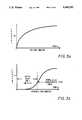
- FIGS. 3a-3bare illustrations of idealized waveforms for the current flowing through an output inductor and across a spark gap in an ignition system, wherein the two current waveforms of FIGS. 3a-3b result from inductor having a non-saturating and saturating core, respectively;
- FIG. 4is a graph of three current waveforms A, B and C showing the actual (A and B) and theoretical (C) current flow through an output inductor and across a spark gap in an ignition system, wherein waveforms A and C result from non-saturating inductor cores and waveform B results from a saturating inductor core;
- FIG. 5is an isolated and perspective view of an output inductor of an ignition system according to the invention, illustrating a sensing device associated with the inductor for use in diagnostics;
- FIG. 6is a circuit diagram according to an exemplary embodiment of the invention of a low voltage-to-high voltage converter and an energy storage device for providing a source of high energy to the spark gap;
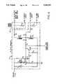
- FIG. 7is a circuit diagram according to an exemplary embodiment of the invention of a trigger circuit for initiating the transfer of energy from the energy storage device to the spark gap of the ignition system;
- FIG. 8is a circuit diagram according to an exemplary embodiment of an output circuit of a unipolar ignition system for use with the DC-to-DC converter and trigger circuits of FIGS. 6 and 7, respectively;
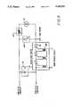
- FIG. 9is a block diagram of the ignition system of the invention according to a second embodiment, incorporating provisions for responding to the controls of a turbine engine in order to synchronize spark timing to the starting cycle of the turbine.
- a unipolar ignition system circuitincludes a DC-to-DC converter 11, a logic circuit 13 and solid state switch 15. From a DC source 17 of relatively low voltage (e.g., 28 volts), the DC-to-DC converter 11 delivers a potential of approximately 2500 volts to an energy storage device 19 which is most commonly a capacitor as illustrated in FIG. 6. A broad band filter 20 is provided between the voltage source 17 and the DC-to-DC converter 11 which prevents high frequency noise generated by the exciter from escaping via the DC power input. It also protects the converter 11 from transients present on the aircraft electrical power system.
- a DC-to-DC converter 11From a DC source 17 of relatively low voltage (e.g., 28 volts), the DC-to-DC converter 11 delivers a potential of approximately 2500 volts to an energy storage device 19 which is most commonly a capacitor as illustrated in FIG. 6.
- a broad band filter 20is provided between the voltage source 17 and the DC-to-DC converter 11 which prevents high frequency noise generated by the exciter from
- DC-to-DC converterswell known in the art may be utilized in the ignition system of the invention.
- One type of converter known in the art as a "flyback" type converterutilizes a charge pump technique to build up the voltage at the energy storage device over a number of charge cycles. Once the charge cycles have built the voltage at the energy storage device 19 to a predetermined level, the charge pumping is interrupted, and the energy storage device discharges into a semiconductor ignitor plug 21 of the ignition system.
- the embodiment of the DC-to-DC converter 11 illustrated in FIG. 6is a flyback type converter having the foregoing characteristics, it will be appreciated by those skilled in the design of ignition systems that other variations of flyback converters or other types of DC-to-DC converters may be substituted without deviation from the spirit of the invention.
- the energy sensor 23responds by activating the trigger circuit 25 which turns on the solid state switch 15 and allows the energy in the storage device to be transferred to an output circuit which includes the commercially available semiconductor ignitor plug 21.
- the output circuitalso includes a saturable inductor 27 and a freewheeling diode 29.
- the saturable inductor 27introduces a phase lag between voltage and current such that the voltage first appears at the spark gap of the plug 21 in order to form a plasma before a current surge occurs.
- the freewheeling diode 29prevents oscillation, resulting in a unipolar discharge current.
- the energy sensor 23also starts a timer 30 which disables the DC-to-DC converter 11 so that the system does not attempt to simultaneously discharge and charge the storage device, and which holds it disabled to provide a delay before the next spark.
- the spark rate which is established by the timer 30must be chosen as a compromise between adequate spark rate to ignite the turbine and low enough spark rate to ensure long ignitor plug life. Also, modern safety standards increasingly require continuous operation of the ignition system in foul weather, and during critical operating conditions of an aircraft. The continuous operation assures a relight if a flame-out occurs.
- an optional spark burst circuit 31is added which alters the spark rate set by timer 30, as will be discussed in reference to FIG. 7.
- the spark burst circuit 31switches the timer 30 to a high pulse rate condition.
- the spark burst circuitswitches the timer back to a lower (maintenance) rate, which can be operated continuously for safety, but without prematurely wearing out the ignitor plug.
- the lower spark ratemay also allow the exciter components to be smaller, since they would not have as high a thermal stress as would exist with continuous high-rate sparking.
- the spark burst circuit 31generates a repetition of sparks for a predetermined time period where the repetition is at an average rate greater than the average rate of repetition which continues after ignition occurs.
- spark burst circuit 31is activated upon application of DC power 17 to the unit by closing of switch 32.
- the sparking sequenceis initiated at a fixed time relative to the engine starting sequence automatically synchronizing the two without requiring extra wiring connections.
- the circuitis also reactivated any time the power is interrupted and reapplied. This provides a high spark rate for starting the engine, followed by a lower rate which provides relight capability without prematurely wearing out the ignitor plug 21.
- the inductor 27includes a saturable core, thereby controlling the discharge current which both protects the solid state switch 15 and ensures a reliable ignition of fuel under all types of ambient conditions.
- the saturable inductor 27acts like a high inductance, limiting di/dt for the first few microseconds after the solid state switch 15 is closed.
- the solid state switch 15is given time to turn on before full current is achieved. This ensures a rate of current rise (di/dt) that will not stress the solid state switch 15 to an extent which shortens its rated life expectancy.
- the inductor 27When the inductor 27 saturates, its effective impedance is reduced, thereby providing a high pulse current at the gap which reliably ignites the mixture. Moreover, the initially high inductance provides a highly desirable extended lag between voltage and high current at the gap of the plug 21. Although a complete understanding of the spark phenomenon at the gap of the plug 21 is not appreciated in the art, applicant hypothesizes that the lag produces several desirable effects. Specifically, the ionization phase is completed before a current surge occurs; thus, the arc is formed in the plasma above the semiconductor material, and less heat is lost by surface conduction to the plug and semiconductor. Also, the less sudden application of power may result in less acoustic (shock), optical and electromagnetic radiation losses, and consequently more conversion to useful heat.
- the inductor 27cooperates with a unidirectional device such as a freewheeling diode 29 in FIG. 1 to maintain a spark after the energy storage device 19 has been fully discharged. Energy stored in the inductor 27 during the discharge of the storage device 19 is released through the unidirectional diode 29 upon completion of the discharge by the storage device.
- the energy dissipated at the ignitor plug 21is initially sourced from the energy storage device 19, forming the initial discharge current loop I 1 through the solid state switch 15 and inductor 27.
- the inductor 27cooperates with the unidirectional diode 29 to effectively shunt the discharge current away from the solid state switch 15 and the energy storage device 19 and forming a second current loop I 2 .
- By shunting the energy storage device 19, "ringing" between the storage device and inductor 27is prevented which accounts for the unipolar output, and the solid state switch 15 is not required to handle current for the entire life of the spark.
- the characteristic di/dt provided by a conventional inductoris substantially different from the di/dt of an inductor having a saturable core (FIG. 3b).
- the di/dtstarts out very high and then more gradually builds to a peak as the di/dt decreases to zero.
- a saturable core inductor at firstis characterized by a monotonically increasing di/dt, and this condition continues to exist until the inductor saturates.
- dL/diis the change of inductance with respect to current due to the saturating of the core material.
- the inductancedrops and the net di/dt actually increases during the saturation process.
- the di/dtreturns to a monotonically decreasing value which goes to zero when peak current is reached.
- the idealized waveformhas been bisected into an initial low current and low di/dt time and a subsequent high current and high di/dt time.
- the core of the inductoris saturating and the effective inductance of the inductor is decreasing, causing the di/dt to increase.
- waveform Ais the current at an ignitor plug of a system utilizing a saturable core inductor in accordance with the invention. As can be seen from an inspection of waveform A, it has the characteristic shape described in connection with FIG. 3b.
- the di/dtis low and the solid state switch of the system experiences only a relatively low level current as it turns on. As the core of the inductor reaches saturation, the current begins to rise relatively quickly as the inductance lessens.
- waveform Bresults.
- the peak energy delivered by the waveform Bmust be limited to significantly less than the peak energy from waveform A. If the peak energy from a conventional inductor is equal to that provided by a saturable core inductor as indicated by theoretical waveform C, the fast initial di/dt creates relatively high current levels before the solid state switch completes its transition from off to on. These high current levels destructively heat the solid state switch and make it an impractical device for use in a conventional unipolar ignition which does not incorporate this invention.
- the saturable-core inductor 27will generally have a closed magnetic path, or at most a very small air gap. It is known in the art that a toroid configuration for the magnetically permeable material comprising the core of the inductor works well in providing a saturable core.
- a very high density iron powder corewas used for the toroid.
- the high densitygives the toroid high permeability (e.g., approximately 75) which results in very high initial inductance for a given size and number of turns of winding.
- Several other characteristics of the materialmake it a good choice.
- the toroid and its main winding 33 as shown in FIG. 5must be sized so that three conditions are met.
- the saturated inductance of the inductormust be chosen to control the peak current during the discharge of energy at the gap of the plug.
- the initial inductance of the inductormust be sufficiently great to limit the initial current to a relatively small value by limiting the value of di/dt.
- the third condition that must be satisfied by the inductoris related to the physical volume of the toroid which affects how much energy the saturable inductor may store. The delay between the initial appearance of high voltage at the ignition plug and the occurrence of a high di/dt at the plug results from the inductor's ability to absorb energy and later release it.
- the saturable core of the inductormay be used to provide monitoring of the spark characteristics and behavior over time.
- a sensing devicecan be realized for monitoring the behavior of the spark current.
- the signal from the secondary winding 35does not duplicate the waveform of the spark current, the secondary signal can be correlated to the current waveform in a manner which allows determination of the quality of the spark, conditions of the ignitor plug 21, performance of the exciter circuitry and of the general combustion/ignition process.
- auxiliary voltage and/or current transformersare used for this purpose, but they are additional hardware parts which invariably cause insertion losses and are physically difficult to place in a circuit such as the exciter circuit for an ignition system. Furthermore, placement of an auxiliary transformer at an appropriate monitoring point can adversely affect the waveforms instead of only monitoring them.
- a secondary winding 35 on the same saturable-core toroid 27 as illustrated in FIG. 5provides an isolated signal which is safe, low-voltage and reflects the behavior of the inductor and the system.
- tape 36wrapped about the toroid 27 as an insulation between the windings of the inductor 22 and the windings of the sensor 35.
- the main winding 33 of the inductorwill generally have a large number of turns (e.g., 68). If the secondary winding 35 has one turn, the step-down ratio will be 1/68. Therefore, for an output voltage of 2,500 volts, the diagnostic output from the secondary will be limited to about 36 volts. From the secondary winding, the signal is delivered to a diagnostic unit 37 for analysis by a variety of conventional analog or digital methods. The results of any analysis provided by the diagnostic unit may be used to indicate performance of the spark current or to signal the need for maintenance or ignitor replacement.
- the diagnostic systemcan distinguish the following conditions: 1) failed plug which appears as an open circuit; 2) performance indication which is based on spark duration; 3) electrical failure of the lead or severe fouling of the plug which appears as a short circuit; and 4) failure of the exciter which results in no output pulse.
- FIGS. 6, 7 and 8An illustration of a specific embodiment of the ignition system circuit according to the invention is shown in FIGS. 6, 7 and 8. Although this specific embodiment is presently applicant's design choice, it will be appreciated by those skilled in the art that other particular designs of unipolar ignition systems may be equally well suited for applicant's invention.
- filtered poweris delivered to the DC-DC converter 11 by the EMI filter 20 which charges C1.
- a small currentflows from capacitor C1 to resistor R2, zener diode Z1 and resistor R1 to ground.
- This currentis delivered to the primary N1 of the transformer T1 by way of the capacitor C1. From the transistor Q1, the current flows through the resistor R1 to ground.
- the transistor Q1is preferably a power MOSFET, N-channel enhancement mode device.
- the secondary winding N2 of the transformer T1is a feedback winding which causes a positive voltage to be fed back to the base of the MOSFET Q1 via the resistor R5 and capacitor C2.
- the feedback of the positive voltagecauses the MOSFET Q1 to be fully turned on by way of a hard forward bias.
- a zener diode Z1clamps the feedback voltage from the winding N2 at a level which does not exceed the rated value (V gs ) of the gate-to-source junction of the MOSFET Q1.
- the polarity of the outputs from the secondary windings N2 and N3 of the transformer T1are positive.
- the positive potential from the outputs of N2 and N3cooperate with the diode D4 to effectively de-couple the DC-to-DC converter 11 (including the primary and secondaries of the transformer T1) from the energy storage device 19 of the system which is the capacitor C5 in FIG. 6.
- the diodesees a positive voltage (e.g., approximately 1,000 volts) when a new charging cycle begins.
- the main storage capacitor C5becomes charged to a high negative voltage (e.g., approximately -2,500 volts); therefore, at the end of the charging cycle the diode D4 must block full range of the potential energy (e.g., at least 1,000 plus 2,500 volts or 3,500 volts).
- a high negative voltagee.g., approximately -2,500 volts
- the converterresponds to a voltage across resistor R1 which is proportional to the current through the primary N1 of the transformer T1.
- the voltage across the current sensing resistor R1is approximately 0.75 volts which is enough to turn on the transistor Q2 via the voltage divider network of R3, and R4.
- the gate of MOSFET Q1is forced low, thus turning off Q1 and opening the current path of the primary current and thereby limiting the current to three amperes.
- This techniqueis known in the art as current-mode control.
- the magnetic field coupling the windings N1, N2 and N3collapses, and the energy stored in the winding N1 is transferred to the secondary windings N2 and N3.
- the windings N2 and N3are typically a single winding with a tap.
- the primary currentis interrupted and the energy stored in the winding N1 is transferred to the secondary windings N2 and N3, the polarity of the energy stored in the secondary windings is reversed, thereby causing the outputs of the secondary windings to assume a negative potential.
- the output voltage from the winding N3is clamped by the diode D4 to a predetermined voltage relative to the negative plate of the main storage capacitor C5. Accordingly, the negative potential at the output of the secondary winding N3 creates an output current which charges the capacitor C5 in the negative direction.
- the tap output between the secondary windings N2 and N3provides a relatively low voltage to the capacitor C4 which is used as a source of energy by the logic circuit 13.
- the voltage V N2charges the capacitor C4 through a diode D5 and resistor R8 to a predetermined voltage (e.g., -80 volts) as discussed hereinafter in connection with the trigger circuit 25 shown in FIG. 7.
- a predetermined voltagee.g., -80 volts
- the voltage at the center tap between windings N2 and N3is coupled back to the MOSFET Q1 in the DC-to-DC converter 11 via resistor R5 and capacitor C2.
- the energy sensor circuit 23senses the voltage at the energy storage capacitor C5 by way of a voltage divider, R11 and R12.
- a voltage dividerR11 and R12.
- the solid state switch 15is closed so as to transfer the energy stored in the capacitor C5 to the spark gap.
- the solid state switch 15is preferably a single SCR 41 or a series of SCRs which are fired by way of pulse transformers 39, as shown in FIG. 8.
- a voltage divider networkcomprising R10, R11, and R12 in FIG. 7 biases the gate of an N-channel JFET Q6 such that it remains on.
- the JFET Q6holds the transistor Q4 in an off condition because the JFET Q6 provides an effective shunt circuit for the base of the transistor Q4.
- the JFET Q6approaches a cutoff condition.
- a switch in the trigger circuit 25comprised of transistors Q4 and Q5 is closed, allowing the energy stored in capacitor C4 to be discharged into the pulse transformers 39 of the solid state switch in FIG. 8.
- the gate-to-source voltage of the JFET Q6is sufficiently negative to turn off the Q6, thereby allowing a current to flow in the base of the transistor Q4 via the resistor R10 and zener diode Z3.
- the transistor Q4turns on, the transistor Q5 is also being turned on.
- the changing biasing of the collector, emitter and base of the transistor Q4complements the biasing of the transistor Q5 such that it turns on and accelerates the turning on of the transistor Q4.
- the combination of transistors Q4 and Q5will latch in the on-state until C4 is fully discharged.
- the transistors Q4 and Q5 and the resistors R16 and R17function as an SCR-type device for delivering a trigger signal to the SCRs 41 comprising the solid state switch 15 via the aforementioned pulse transformers 39, as shown in FIG. 8.
- a discharge currentis developed from the capacitor C4 which must also flow through the resistor R9 and the zener diode Z2 in the timer circuit 30.
- the discharge currentin cooperation with the resistor R9 and zener diode Z2 causes a pulse to appear in the timer circuit 30.
- the timeris an RC network composed of resistor R6 and capacitor C3.
- the capacitor C3is charged by the pulse via a diode D3. However, the diode allows the capacitor C3 to discharge only through resistor R6.
- the charged capacitor C3turns on a MOSFET Q3. As the voltage on the capacitor C3 is discharged through the resistor R6, the MOSFET Q3 turns off. While the MOSFET Q3 is on, however, the timer circuit 30 sends a disable signal to the DC-DC converter 11 of FIG. 6.
- an optinal spark burst circuit 31which connects to the timer 30 at the gate of Q3. As was discussed in connection with FIG. 1, the spark burst circuit 31 alters the spark rate either abruptly or gradually so that a temporary high spark rate exists when starting the engine, followed by a lowering of the rate thereafter.
- the arrival of DC input power via the EMI filteris used to indicate that an ignition sequence is beginning.
- the voltageis applied to an RC timing network comprised of R18 and C9.
- the junction of R18 and C9rises instantly with the applied voltage, and then decays slowly toward ground as R8 charges C9.
- the initial rise of voltage at the junctionis coupled to the gate of a MOSFET Q7 which turns on immediately with its gate pulled high. As the junction voltage decays toward zero, the gate-source voltage decreases until V gs OFF is reached (i.e., 1-2 volts) and then the Q7 switches off.
- the timer 30is disabled, because the gate of Q3 is pulled low by Q7. With Q3 forced off, the DC-DC converter is not disabled, and will run continuously. This will charge and fire the exciter at a high rate. Once Q7 turns off, the high impedance of its drain-source circuit decouples it from the timer circuit.
- spark burst time delaycould be from an external signal, for example from the ECU.
- an alternative digital methodis anticipated which allows a preset number of sparks to occur at a fixed high rate, and then switches to a low rate.
- Such an implementationcould take the form of a preset digital counter, or could be implemented by an appropriate instruction sequence for a microcontroller which performs the complete logic functions of an ignition system.
- the solid state switch 15 of the ignition systemis preferably realized by way of a series of connected SCRs 41, each having a high standoff voltage and very high pulse current capacity. Applicant notes it would be preferable to use one SCR, but it is unlikely to find an SCR rated for the required voltage (e.g., 2,500 volts).
- the energy stored in the storage capacitor C5is discharged to the semiconductor ignitor plug 21 via the saturable inductor 27.
- the negative plate of the capacitor C5is effectively pulled to an electrical ground, thereby causing the positive plate of the capacitor C5 to swing from a ground potential to a high positive voltage (e.g., +2,500 volts DC).
- a high positive voltagee.g., +2,500 volts DC
- the positive voltage on the capacitor C5reverses the bias on the diode D9, thereby effectively de-coupling the positive plate of the capacitor from the ground potential, typically defined by the potential of the housing for the ignition system.
- the high potential at the positive plate of the capacitor C5is presented to the ignitor plug 21 by way of the saturable inductor 27.
- the energy for generation of a spark(CV 2 ) is first stored as an electrical potential in the capacitor C5 and second is transferred to the saturable inductor 27 where it is stored as magnetic energy (LI 2 ).
- the diode D9becomes forward biased and maintains the current across the gap of the plug 21 and through the diode D9 and the saturable inductor 27. With the full discharge of the capacitor C5, the solid state switch 15 is no longer part of the current path.
- the preferred solid state switch 15should have a good physical construction capable of withstanding repeated thermal cycling.
- the SCRs 41must have adequate chip area to give them a low forward voltage drop since the surge currents are very high and efficiency is compromised by losses in the switch 15. These parameters for the solid state switch 15 must be maintained over the entire temperature and pressure ranges of the intended application. Additionally, the turn-on time of the switch 15 must be fast relative to the delay available from the saturable core inductor 27. However, the di/dt rating of the SCR is not as important since the rate of current rise is controlled by the saturable inductor during the turn-on period when the switch 15 is most susceptible to damage.
- the ignition window(the time interval when a spark most probably causes ignition) may be very short, and fixed rate sparks can easily occur just before and after the ideal time.
- the spark dischargeoccurs automatically when the voltage at the energy storage device 19 reaches a level at which the desired amount of spark energy, CV 2 , has been stored.
- this levelis fixed by the breakdown voltage of the arc-gap, which cannot maintain its off-state in the presence of a fully charged energy storage capacitor.
- Timing the application of DC power to the exciter circuitry of the ignition systemis not an acceptable solution for placing the spark within the ignition window since the charging time of the exciter circuitry depends upon the value of DC input voltage (i.e , 10-30 volts) and thus the interval from the application of DC power until the initiation of a spark will vary considerably.
- the logic circuit 13 of FIG. 1may be modified to provide a configuration wherein the energy sensor 23 disables the DC-to-DC converter 11, but does not cause the trigger circuit 25 to immediately fire the solid state switch 15. Instead, the firing of the solid state switch 15 is delayed until a command from an external input. After the energy storage device 19 has reached its full energy, the DC-to-DC converter is disabled as explained in connection with FIG. 1.
- the trigger circuit 25must also wait for a synchronization command from the Engine Control Unit (ECU) 43.
- the ECUgenerally performs a sequence of functions to start the engine.
- the sequenceusually includes the following: 1) apply DC voltage to the exciter circuitry; 2) engage the starter motor to accelerate the turbine to a percentage of full speed; 3) start fuel spray; 4) fire the ignitor system at a precise moment of best ignition condition; and 5) continue to fire the ignition system or allow it to continue at its own rate.
- the ECUis a commercially available unit which controls the operation of the turbine engine; it most generally controls the fuel flow in response to altitude, torque, RPM and commands from the pilot. It is reasonably sophisticated and capable of providing commands to the ignition system to optimize performance. Another useful signal that the ECU is capable of generating is a "spark energy" command signal which can directly control the energy sensor 23 to halt the charging of the energy storage device 19 at any particular level.
- the signal to the trigger circuit 25 which initiates the sparkis made dependent upon two conditions.
- the energy sensor 23must indicate that the energy storage device 19 is charged to the level commanded by the ECU 43.
- the synchronizing "fire" command from the ECUmust occur, and the ECU delays this command until it has established the correct fuel flow for the altitude (mixture) and the engine has reached the proper starting speed. At this time, conditions are optimum for the first spark to ignite the mixture.
- the AND gate 45 in FIG. 9defines the two-condition requirement for the first spark; it also allows the ECU 41 to control the successive sparks by several optional methods.
- the ECUIf the ECU needs to generate just one spark, it returns the "fire" command line to an off condition--thus it merely pulses the line. If the ECU decides additional sparks controlled by its own timing, then it successively pulses the "fire” command each time a spark is desired--provided that it has allowed the exciter enough time to recharge the energy storage device. If the ECU decides to allow the exciter to generate sparks at its predefined rate, then it leaves the "fire" command line in the on condition. As is true for any AND function, if one input of the AND gate 45 is maintained in the on condition, then the other input is transmitted through to the output unaltered.
- the trigger circuit 25will be responsive to the energy sensor 23 as discussed in reference to FIG. 1, and will trigger a spark each time the energy sensor 23 detects that the energy storage device is recharged.
- an ignition systemwhich provides improved performance relative to conventional ignition systems, particularly unipolar ignitions for turbine engines.
- the inventionutilizes solid state switching and controls to provide a highly versatile ignition system having a characteristic high energy spark current which ensures reliable ignition without stressing the solid state components.
- the characteristic spark currentis thought to also reduce the stress of a semiconductor-type ignitor plug, thereby effectively extending the life of the plug.
- the inventionprovides for the precise timing of an ignition sequence by responding to an external signal, such as a timing signal from a control unit of the engine.
- the solid state devicesalso provide for an ignition sequence that begins with a burst of sparks for the purpose of igniting the engine fuel, followed by continued repeating of sparks at an average rate much less than the average rate of the burst.
- the saturable output inductor of the ignition systemis advantageously utilized to provide a diagnostics signal indicative of the quality of the spark at the plug.
Landscapes
- Engineering & Computer Science (AREA)
- Chemical & Material Sciences (AREA)
- Combustion & Propulsion (AREA)
- Mechanical Engineering (AREA)
- General Engineering & Computer Science (AREA)
- Ignition Installations For Internal Combustion Engines (AREA)
Abstract
Description
Claims (8)
Priority Applications (3)
| Application Number | Priority Date | Filing Date | Title |
|---|---|---|---|
| US07/697,084US5245252A (en) | 1988-11-15 | 1991-05-08 | Apparatus and method for providing ignition to a turbine engine |
| US08/074,654US5399942A (en) | 1988-11-15 | 1993-06-08 | Apparatus and method for providing ignition to a turbine engine |
| US08/394,694US5561350A (en) | 1988-11-15 | 1995-02-24 | Ignition System for a turbine engine |
Applications Claiming Priority (2)
| Application Number | Priority Date | Filing Date | Title |
|---|---|---|---|
| US07/271,723US5065073A (en) | 1988-11-15 | 1988-11-15 | Apparatus and method for providing ignition to a turbine engine |
| US07/697,084US5245252A (en) | 1988-11-15 | 1991-05-08 | Apparatus and method for providing ignition to a turbine engine |
Related Parent Applications (1)
| Application Number | Title | Priority Date | Filing Date |
|---|---|---|---|
| US07/271,723ContinuationUS5065073A (en) | 1988-11-15 | 1988-11-15 | Apparatus and method for providing ignition to a turbine engine |
Related Child Applications (1)
| Application Number | Title | Priority Date | Filing Date |
|---|---|---|---|
| US08/074,654ContinuationUS5399942A (en) | 1988-11-15 | 1993-06-08 | Apparatus and method for providing ignition to a turbine engine |
Publications (1)
| Publication Number | Publication Date |
|---|---|
| US5245252Atrue US5245252A (en) | 1993-09-14 |
Family
ID=26955089
Family Applications (3)
| Application Number | Title | Priority Date | Filing Date |
|---|---|---|---|
| US07/697,084Expired - LifetimeUS5245252A (en) | 1988-11-15 | 1991-05-08 | Apparatus and method for providing ignition to a turbine engine |
| US08/074,654Expired - LifetimeUS5399942A (en) | 1988-11-15 | 1993-06-08 | Apparatus and method for providing ignition to a turbine engine |
| US08/394,694Expired - LifetimeUS5561350A (en) | 1988-11-15 | 1995-02-24 | Ignition System for a turbine engine |
Family Applications After (2)
| Application Number | Title | Priority Date | Filing Date |
|---|---|---|---|
| US08/074,654Expired - LifetimeUS5399942A (en) | 1988-11-15 | 1993-06-08 | Apparatus and method for providing ignition to a turbine engine |
| US08/394,694Expired - LifetimeUS5561350A (en) | 1988-11-15 | 1995-02-24 | Ignition System for a turbine engine |
Country Status (1)
| Country | Link |
|---|---|
| US (3) | US5245252A (en) |
Cited By (26)
| Publication number | Priority date | Publication date | Assignee | Title |
|---|---|---|---|---|
| US5352955A (en)* | 1991-09-27 | 1994-10-04 | Eyquem | High energy ignition generator for gas turbines |
| EP0679804A1 (en)* | 1994-04-25 | 1995-11-02 | Simmonds Precision Engine Systems, Inc. | Exciter circuit using gated switches |
| US5488536A (en)* | 1993-04-01 | 1996-01-30 | Simmonds Precision Engine Systems, Inc. | Exciter circuit using gated switches |
| US5550434A (en)* | 1994-05-23 | 1996-08-27 | Northrop Corporation | Boost-mode energization and modulation circuit for an arc lamp |
| US5561350A (en) | 1988-11-15 | 1996-10-01 | Unison Industries | Ignition System for a turbine engine |
| US5587630A (en)* | 1993-10-28 | 1996-12-24 | Pratt & Whitney Canada Inc. | Continuous plasma ignition system |
| US5592118A (en)* | 1994-03-09 | 1997-01-07 | Cooper Industries, Inc. | Ignition exciter circuit with thyristors having high di/dt and high voltage blockage |
| EP0753662A2 (en) | 1995-07-14 | 1997-01-15 | Unison Industries Limited Partnership | Method and apparatus for controllably generating sparks in an ignition system or the like |
| US5656966A (en)* | 1994-03-09 | 1997-08-12 | Cooper Industries, Inc. | Turbine engine ignition exciter circuit including low voltage lockout control |
| US5862033A (en)* | 1997-02-13 | 1999-01-19 | Unison Industries Limited Partnership | Exciter circuit |
| EP1088376A4 (en)* | 1998-04-27 | 2001-07-11 | Cymer Inc | Magnetic modulator voltage and temperature timing compensation circuit |
| US6295804B1 (en) | 1998-04-09 | 2001-10-02 | The Board Of Trustees Of The University Of Illinois | Pulsed thruster system |
| US6297568B1 (en) | 1998-12-23 | 2001-10-02 | Champion Aerospace Inc. | Inductive ignition circuit |
| US6484707B1 (en)* | 2000-09-29 | 2002-11-26 | Unison Industries, Inc. | Method and apparatus for generating a sustained arc at a sparking device |
| US20050276000A1 (en)* | 2004-06-15 | 2005-12-15 | Wilmot Theodore S | Solid state turbine engine ignition exciter having elevated temperature operational capabiltiy |
| US20100154382A1 (en)* | 2008-12-23 | 2010-06-24 | Scott Brian Wright | Method and systems for adaptive ignition energy |
| US20140053820A1 (en)* | 2012-08-27 | 2014-02-27 | Honda Motor Co., Ltd. | Ignition device for battery-less engine and method for starting and operating battery-less engine |
| US8863530B2 (en) | 2008-10-30 | 2014-10-21 | Power Generation Technologies Development Fund L.P. | Toroidal boundary layer gas turbine |
| US9052116B2 (en) | 2008-10-30 | 2015-06-09 | Power Generation Technologies Development Fund, L.P. | Toroidal heat exchanger |
| US9622331B2 (en) | 2012-12-26 | 2017-04-11 | Unison Industries, Llc | Discharge switch device for ignition excitation system |
| EP3196444A1 (en)* | 2016-01-21 | 2017-07-26 | Champion Aerospace LLC | Solid state spark device and exciter circuit using such a device |
| US20170251858A1 (en)* | 2016-03-04 | 2017-09-07 | CE Brands, LLC | Smart slow cooker |
| US20180106196A1 (en)* | 2016-10-19 | 2018-04-19 | Honeywell International Inc. | Method and system for supplying charge pulses to a chip zapper of a gas turbine engine |
| US11519335B1 (en) | 2021-08-27 | 2022-12-06 | Unison Industries, Llc | Turbine engine ignition system and method |
| RU221116U1 (en)* | 2023-07-03 | 2023-10-19 | Федеральное государственное бюджетное образовательно учреждение высшего образования "Уфимский университет науки и технологий" | CAPACITIVE IGNITION DEVICE |
| US20240191681A1 (en)* | 2022-12-08 | 2024-06-13 | Hamilton Sundstrand Corporation | Engine ignition systems and control methods therefor |
Families Citing this family (27)
| Publication number | Priority date | Publication date | Assignee | Title |
|---|---|---|---|---|
| US5495150A (en)* | 1995-03-03 | 1996-02-27 | Northrop Grumman Corporation | Sequential, differential ignition of series operated arc lamps |
| US5654868A (en)* | 1995-10-27 | 1997-08-05 | Sl Aburn, Inc. | Solid-state exciter circuit with two drive pulses having indendently adjustable durations |
| KR20010031093A (en)* | 1997-10-14 | 2001-04-16 | 로버트 엠. 포터 | System for plasma ignition by fast voltage rise |
| US6195247B1 (en) | 1998-06-02 | 2001-02-27 | Pratt & Whitney Canada | Exciter controlled by FADEC system |
| US6304040B1 (en)* | 1999-07-12 | 2001-10-16 | Hughes Electronics Corporation | Starter circuit for an ion engine |
| DE19935025C2 (en)* | 1999-07-26 | 2001-05-23 | Beru Ag | Ion current glow plug and control device for controlling it |
| CA2383205A1 (en)* | 1999-09-15 | 2001-03-22 | Gunter Schemmann | Electronic circuits for plasma-generating devices |
| US6104143A (en)* | 1999-10-01 | 2000-08-15 | Peabody Engneering Corporation | Exciter circuit with solid switch device separated from discharge path |
| DE10127362C2 (en)* | 2001-06-06 | 2003-05-15 | Siemens Ag | Ignition system for an internal combustion engine |
| US6603216B2 (en)* | 2001-10-10 | 2003-08-05 | Champion Aerospace Inc. | Exciter circuit with ferro-resonant transformer network for an ignition system of a turbine engine |
| GB0203582D0 (en)* | 2002-02-15 | 2002-04-03 | Smiths Group Plc | Ignition circuits |
| US6670777B1 (en) | 2002-06-28 | 2003-12-30 | Woodward Governor Company | Ignition system and method |
| US6922057B2 (en)* | 2002-11-01 | 2005-07-26 | Visteon Global Technologies, Inc. | Device to provide a regulated power supply for in-cylinder ionization detection by using a charge pump |
| US7204090B2 (en)* | 2004-06-17 | 2007-04-17 | Pratt & Whitney Canada Corp. | Modulated current gas turbine engine starting system |
| US7509812B2 (en)* | 2004-08-20 | 2009-03-31 | Hamilton Sundstrand Corporation | Dual ignition system for a gas turbine engine |
| US7095601B2 (en)* | 2004-08-20 | 2006-08-22 | Hamilton Sundstrand Corporation | High energy primary spark ignition system for a gas turbine engine |
| US7191084B2 (en)* | 2005-04-20 | 2007-03-13 | General Electric Company | Method and apparatus for gas turbine engine ignition systems |
| US7768767B2 (en)* | 2006-05-05 | 2010-08-03 | Pratt & Whitney Canada Corp. | Triggered pulsed ignition system and method |
| DE102006025073A1 (en)* | 2006-05-30 | 2007-12-06 | Robert Bosch Gmbh | ignition coil |
| US20090278509A1 (en)* | 2008-05-06 | 2009-11-12 | Samuel Boyles | Battery charging and isolation system for gas engine |
| RU2463522C1 (en)* | 2011-04-11 | 2012-10-10 | Открытое акционерное общество "Уфимское научно-производственное предприятие "Молния" | Method of igniting aircraft gas turbine combustion chamber |
| ITMI20111669A1 (en)* | 2011-09-16 | 2013-03-17 | St Microelectronics Srl | GRADUAL IGNITION IN A COMBUSTION ENGINE IGNITION SYSTEM |
| RU2494314C1 (en)* | 2012-02-03 | 2013-09-27 | Открытое акционерное общество "Уфимское научно-производственное предприятие "Молния" | Ignition method of combustion chamber of aircraft gas-turbine engines |
| US9784232B1 (en)* | 2016-04-01 | 2017-10-10 | Marshall Electric Corp. | Forced frequency ignition system for an internal combustion engine |
| RU2697121C1 (en)* | 2018-09-27 | 2019-08-13 | Общество с ограниченной ответственностью "Научно-производственная фирма "Теплофизика" | Ignition device for ignition of combustion chamber of gas turbine engine |
| US11356024B2 (en) | 2018-12-06 | 2022-06-07 | Unison Industries, Llc | Ignition exciter assembly and method for charging a tank capacitor for an ignition exciter |
| US20210172376A1 (en)* | 2019-12-10 | 2021-06-10 | General Electric Company | Combustor ignition timing |
Citations (65)
| Publication number | Priority date | Publication date | Assignee | Title |
|---|---|---|---|---|
| FR1097275A (en)* | 1953-02-09 | 1955-07-04 | Thomson Houston Comp Francaise | Device for the production of non-oscillating electric discharges |
| US2799809A (en)* | 1956-03-01 | 1957-07-16 | Gen Electric | Capacitor discharge ignition system |
| US2896123A (en)* | 1953-11-23 | 1959-07-21 | Gen Lab Associates Inc | Spark producing apparatus including saturable core transformer |
| US2938147A (en)* | 1959-02-17 | 1960-05-24 | John J Rose | Continuous ignition system for a turbojet engine |
| US2985797A (en)* | 1958-10-30 | 1961-05-23 | Westinghouse Electric Corp | Application of semiconductors to ignition circuitry |
| US2995685A (en)* | 1958-05-01 | 1961-08-08 | Gen Electric | Ignition system |
| US3111632A (en)* | 1960-06-17 | 1963-11-19 | Globe Ind Inc | Transistor oscillator |
| US3129374A (en)* | 1960-12-07 | 1964-04-14 | Westinghouse Electric Corp | Semiconductor protection circuit |
| GB962417A (en)* | 1962-04-16 | 1964-07-01 | Ass Elect Ind | Improvements in and relating to ignition circuit arrangements |
| US3395686A (en)* | 1966-11-03 | 1968-08-06 | Brunswick Corp | Blocking oscillator circuit and capacitor discharge ignition system employing the blocking oscillator circuit |
| US3407795A (en)* | 1966-06-02 | 1968-10-29 | Texaco Inc | Ignition system for internal combustion engines |
| US3421825A (en)* | 1965-06-03 | 1969-01-14 | Ass Elect Ind | Electric spark ignition units |
| US3534719A (en)* | 1968-07-26 | 1970-10-20 | Brunswick Corp | Speed limiting ignition system |
| US3556706A (en)* | 1969-07-16 | 1971-01-19 | Webster Electric Co Inc | Oil burner spark ignition system |
| US3571609A (en)* | 1969-08-20 | 1971-03-23 | Gen Lab Associates Inc | Ignition apparatus selectively operable at different levels of discharge energy |
| US3575153A (en)* | 1968-11-18 | 1971-04-20 | Eltra Corp | Regulated voltage converter |
| US3581726A (en)* | 1969-07-22 | 1971-06-01 | Mallory Electric Corp | Capacitive-discharge system for internal combustion engines |
| US3583378A (en)* | 1969-04-08 | 1971-06-08 | Warren K Pattee | Capacitive discharge solid state ignition system |
| US3584929A (en)* | 1969-12-29 | 1971-06-15 | Motorola Inc | Spark duration for capacitor discharge ignition systems |
| US3629652A (en)* | 1968-06-10 | 1971-12-21 | Rotax Ltd | Ignition systems |
| DE1539195A1 (en)* | 1966-11-19 | 1972-03-23 | Everding Helmut Dipl Ing | Electronic ignition system for mixture-compressing internal combustion engines (Otto engines), which are preferably used to drive motor vehicles |
| US3675077A (en)* | 1971-01-18 | 1972-07-04 | Floyd M Minks | High voltage ignition system transformer |
| US3716758A (en)* | 1971-03-12 | 1973-02-13 | Fiat Spa | Thyristor ignition control device |
| US3731144A (en)* | 1972-02-25 | 1973-05-01 | Bendix Corp | Direct current powered ignition system with blocking oscillator |
| US3740589A (en)* | 1971-02-16 | 1973-06-19 | F Minks | Blocking oscillator with current mode transformer |
| US3769545A (en)* | 1972-05-25 | 1973-10-30 | Kodan Inc | Circuit arrangement for operating electric arc discharge devices |
| US3806305A (en)* | 1972-11-16 | 1974-04-23 | Johnson Service Co | Solid state spark ignition circuit with automatic shut-off |
| US3818885A (en)* | 1973-02-20 | 1974-06-25 | Texaco Inc | High-frequency continuous-wave ignition system |
| US3824432A (en)* | 1972-09-06 | 1974-07-16 | Braun Ag | Battery igniter |
| US3835350A (en)* | 1972-11-29 | 1974-09-10 | Bendix Corp | High energy output inductive ignition system |
| US3838328A (en)* | 1973-03-19 | 1974-09-24 | W Lundy | Capacitive discharge ignition system |
| US3849670A (en)* | 1973-04-13 | 1974-11-19 | Webster Electric Co Inc | Scr commutation circuit for current pulse generators |
| US3869645A (en)* | 1972-03-25 | 1975-03-04 | Lucas Aerospace Ltd | Spark ignition systems |
| US3889160A (en)* | 1972-09-06 | 1975-06-10 | Braun Ag | Spark-producing arrangement for a lighter with a battery |
| US3894273A (en)* | 1974-05-17 | 1975-07-08 | Jr Harry E Newport | Spark ignition circuit for gas burners |
| US3906919A (en)* | 1974-04-24 | 1975-09-23 | Ford Motor Co | Capacitor discharge ignition system with controlled spark duration |
| US3910246A (en)* | 1973-08-10 | 1975-10-07 | Texaco Inc | Continuous-wave high-frequency AC ignition system |
| US3958168A (en)* | 1973-01-10 | 1976-05-18 | Kenneth Grundberg | Electronic control circuit |
| US3961613A (en)* | 1971-12-17 | 1976-06-08 | Texaco Inc. | Controlled spark-duration ignition system |
| US4027198A (en)* | 1975-08-14 | 1977-05-31 | The Bendix Corporation | Capacitor discharge ignition system |
| US4122816A (en)* | 1976-04-01 | 1978-10-31 | The United States Of America As Represented By The Administrator Of The National Aeronautics And Space Administration | Plasma igniter for internal combustion engine |
| US4136301A (en)* | 1976-07-26 | 1979-01-23 | Kabushiki Kaisha Sigma Electronics Planning | Spark plug igniter comprising a dc-dc converter |
| US4154205A (en)* | 1976-08-18 | 1979-05-15 | Semikron, Gesellschaft Fur Gleichrichterbau | Capacitor ignition system for internal-combustion engines |
| US4191911A (en)* | 1978-11-24 | 1980-03-04 | Gerry Martin E | AC power generation control system |
| US4203052A (en)* | 1978-03-20 | 1980-05-13 | Robertshaw Controls Company | Solid state ignition system |
| US4245609A (en)* | 1978-12-18 | 1981-01-20 | Gerry Martin E | Modulated AC ignition system |
| US4247880A (en)* | 1978-02-28 | 1981-01-27 | Yamatake-Honeywell Company Limited | Ignition device for oil burners |
| US4261025A (en)* | 1975-12-03 | 1981-04-07 | Lucas Industries Limited | Spark discharge ignition systems for gas turbine engines |
| US4285321A (en)* | 1979-10-19 | 1981-08-25 | R. E. Phelon Company, Inc. | Capacitor discharge ignition system |
| US4329628A (en)* | 1980-07-31 | 1982-05-11 | Honeywell Inc. | Relaxation oscillator type spark generator |
| US4344122A (en)* | 1980-09-05 | 1982-08-10 | General Electric Company | Current sourced inverter with saturating output transformer |
| US4349008A (en)* | 1979-11-09 | 1982-09-14 | Wainwright Basil E | Apparatus for producing spark ignition of an internal combustion engine |
| US4424556A (en)* | 1981-08-13 | 1984-01-03 | Matsushita Electric Industrial Co., Ltd. | Self-oscillating DC to DC converter |
| US4430628A (en)* | 1978-12-28 | 1984-02-07 | Nilssen Ole K | High efficiency inverter and ballast circuits |
| US4522184A (en)* | 1984-04-23 | 1985-06-11 | Altronic, Inc. | Silicon controlled rectifier shut-off circuit for capacitive discharge ignition system |
| US4535380A (en)* | 1984-05-23 | 1985-08-13 | Robertshaw Controls Company | Ignition system |
| US4561707A (en)* | 1983-03-28 | 1985-12-31 | Mcculloch Corporation | Current-sheet inductor network and pulse-forming systems |
| US4589398A (en)* | 1984-02-27 | 1986-05-20 | Pate Ronald C | Combustion initiation system employing hard discharge ignition |
| US4705013A (en)* | 1985-10-28 | 1987-11-10 | Minks Floyd M | Regulated power supply for a solid state ignition system |
| US4774924A (en)* | 1987-10-22 | 1988-10-04 | Minks Floyd M | Engine spark control apparatus |
| US4791349A (en)* | 1982-03-15 | 1988-12-13 | Minks Floyd D | Electric power system |
| US4833369A (en)* | 1987-10-14 | 1989-05-23 | Sundstrand Corp. | Constant spark rate ignition exciter |
| US4839772A (en)* | 1988-03-21 | 1989-06-13 | Bang H. Mo | Capacitive discharge electronic ignition system for automobiles |
| US4983886A (en)* | 1988-09-20 | 1991-01-08 | Labo Industrie | High-energy ignition generator especially for a gas-turbine |
| US5065073A (en)* | 1988-11-15 | 1991-11-12 | Frus John R | Apparatus and method for providing ignition to a turbine engine |
Family Cites Families (114)
| Publication number | Priority date | Publication date | Assignee | Title |
|---|---|---|---|---|
| US3045148A (en)* | 1962-07-17 | Ignition system with transistor control | ||
| US3049642A (en)* | 1962-08-14 | Firing circuit for ignition systems | ||
| GB529558A (en) | 1939-06-03 | 1940-11-22 | British Thomson Houston Co Ltd | Improvements in and relating to electrical ignition apparatus |
| FR963784A (en) | 1947-01-13 | 1950-07-20 | ||
| GB637286A (en) | 1947-05-29 | 1950-05-17 | British Thomson Houston Co Ltd | Improvements relating to ignition means for combustion chambers |
| GB661410A (en) | 1949-01-31 | 1951-11-21 | Mini Of Supply | Improvements in and relating to current pulse generating circuit arrangements |
| GB682877A (en) | 1949-11-22 | 1952-11-19 | British Thomson Houston Co Ltd | Improvements in and relating to fuel ignition systems |
| US2651005A (en)* | 1951-09-24 | 1953-09-01 | Bendix Aviat Corp | Electrical apparatus |
| US2717335A (en)* | 1952-07-17 | 1955-09-06 | Gen Electric | Ignition system |
| GB762097A (en) | 1952-07-17 | 1956-11-21 | Gen Electric | Improvements in and relating to ignition systems |
| GB762119A (en) | 1953-02-09 | 1956-11-21 | Gen Electric | Improvements in electric capacitor discharge ignition systems |
| GB808991A (en) | 1956-07-04 | 1959-02-18 | Lucas Industries Ltd | Electric ignition apparatus |
| US2980822A (en)* | 1958-09-12 | 1961-04-18 | Gen Motors Corp | Ignition system |
| GB896161A (en) | 1959-05-19 | 1962-05-09 | Rotax Ltd | Ignition systems |
| FR1297338A (en)* | 1961-05-19 | 1962-06-29 | Schlumberger Prospection | Electric oscillation triggered generator |
| US3169212A (en)* | 1961-07-31 | 1965-02-09 | Texas Instruments Inc | Transistorized ignition system |
| GB992288A (en) | 1962-01-12 | 1965-05-19 | Bendix Corp | Improvements in or relating to ignition systems for internal combustion engines |
| GB1035656A (en) | 1962-05-01 | 1966-07-13 | Ass Elect Ind | Improvements in and relating to sparking circuits |
| US3223887A (en)* | 1962-06-29 | 1965-12-14 | Bendix Corp | Electrical apparatus |
| GB1018963A (en) | 1962-11-12 | 1966-02-02 | Lucas Industries Ltd | Ignition systems for gas turbine engines |
| GB997139A (en) | 1963-11-16 | 1965-07-07 | Rolls Royce | Ignition apparatus |
| US3331033A (en)* | 1964-09-10 | 1967-07-11 | Gen Motors Corp | Transistor oscillator power supply system |
| US3302629A (en)* | 1964-09-21 | 1967-02-07 | Motorola Inc | Capacitor discharge ignition system with blocking oscillator charging circuit |
| GB1045812A (en) | 1964-10-01 | 1966-10-19 | Hancock And Co Engineers Ltd | Electronic spark igniter |
| GB1063257A (en) | 1964-12-02 | 1967-03-30 | Lucas Industries Ltd | Spark ignition systems |
| GB1132103A (en) | 1965-02-10 | 1968-10-30 | Rotax Ltd | Spark ignition circuits |
| GB1027259A (en) | 1965-02-15 | 1966-04-27 | Rotax Ltd | Spark ignition apparatus |
| GB1106923A (en) | 1965-03-10 | 1968-03-20 | Lucas Industries Ltd | Spark ignition systems |
| GB1111791A (en) | 1965-03-10 | 1968-05-01 | Lucas Industries Ltd | Spark ignition systems |
| GB1117181A (en) | 1965-03-10 | 1968-06-19 | Lucas Industries Ltd | Spark ignition systems |
| US3505563A (en)* | 1965-03-10 | 1970-04-07 | Ass Elect Ind | Fluid fuel ignition combustion arrangement |
| GB1109158A (en) | 1965-03-11 | 1968-04-10 | Lucas Industries Ltd | Spark ignition systems |
| GB1136243A (en) | 1965-03-26 | 1968-12-11 | Rotax Ltd | Ignition systems |
| GB1102267A (en) | 1966-02-28 | 1968-02-07 | Ass Elect Ind | Improvements in and relating to ignition discharge circuits |
| US3424142A (en) | 1966-11-09 | 1969-01-28 | Ford Motor Co | Oscillator controlled electronic ignition system |
| US3424945A (en)* | 1967-03-27 | 1969-01-28 | Mid Continent Mfg Co | Controlled capacitor-discharge gas turbine ignition system |
| US3450942A (en)* | 1967-04-10 | 1969-06-17 | Bendix Corp | Electrical pulse generating system |
| DE1764105A1 (en) | 1967-04-10 | 1972-02-03 | Bendix Corp | Electric ignition spark generator |
| US3470386A (en)* | 1967-04-21 | 1969-09-30 | Liberty Combustion Corp | Spark detector |
| NL6705849A (en)* | 1967-04-26 | 1967-07-25 | ||
| US3490426A (en) | 1967-07-20 | 1970-01-20 | Tecumseh Products Co | Ignition system |
| US3504658A (en)* | 1967-08-28 | 1970-04-07 | Mallory Electric Corp | Capacitive-discharge ignition system |
| GB1239756A (en) | 1967-11-21 | 1971-07-21 | ||
| US3546528A (en) | 1968-01-24 | 1970-12-08 | Rca Corp | Capacitor discharge ignition circuit |
| JPS5138018B1 (en)* | 1968-01-30 | 1976-10-19 | ||
| US3504490A (en)* | 1968-02-20 | 1970-04-07 | Conductron Corp | Light sensitive apparatus for preventing flameout in combustion engines |
| GB1256885A (en) | 1968-04-23 | 1971-12-15 | ||
| US3531738A (en) | 1968-04-24 | 1970-09-29 | Bendix Corp | Continuous duty ignition system |
| US3551800A (en)* | 1968-06-06 | 1970-12-29 | Ibm | Test apparatus for analyzing the performance characteristics of internal combustion engine ignition systems |
| US3569727A (en)* | 1968-09-30 | 1971-03-09 | Bendix Corp | Control means for pulse generating apparatus |
| CH505984A (en)* | 1969-06-20 | 1971-04-15 | Bosch Gmbh Robert | Ignition system for internal combustion engines |
| US3600887A (en)* | 1969-09-08 | 1971-08-24 | Ford Motor Co | Electrical starting and operating system for gas turbine engine |
| GB1283905A (en) | 1969-10-07 | 1972-08-02 | Fiat Spa | Improvements in or relating to capacitive discharge ignition circuits |
| GB1334230A (en) | 1970-01-29 | 1973-10-17 | Lucas Industries Ltd | Spark ignition systems for internaal combustion engines |
| US3681001A (en)* | 1970-05-15 | 1972-08-01 | Liberty Combustion Corp | Fluid fuel igniter control system |
| GB1353588A (en) | 1970-05-21 | 1974-05-22 | Lucas Industries Ltd | Spark igition systems |
| DE2040913C3 (en) | 1970-08-18 | 1978-06-15 | Volkswagenwerk Ag, 3180 Wolfsburg | Device for the automatic detection of the timing of the ignition voltages in a multi-cylinder internal combustion engine |
| US3793583A (en)* | 1970-09-08 | 1974-02-19 | Allen Group | Secondary waveform analyzer |
| GB1268290A (en) | 1970-10-10 | 1972-03-29 | Nippon Denso Co | Improvements in and relating to ignition devices for internal combustion engines |
| US3793584A (en)* | 1971-03-16 | 1974-02-19 | Tif Instr Inc | Ignition system test instrument and method |
| GB1396280A (en) | 1971-06-18 | 1975-06-04 | Plessey Co Ltd | Spark ignition systems |
| GB1400446A (en) | 1971-07-17 | 1975-07-16 | Lucas Industries Ltd | Spark ignition circuits |
| US3750637A (en)* | 1971-09-07 | 1973-08-07 | F Minks | Alternator-rectifier electronic charging and discharging apparatus for ignition systems and the like |
| US3852623A (en)* | 1972-02-22 | 1974-12-03 | Gen Motors Corp | Timing circuit |
| US3725732A (en) | 1972-02-25 | 1973-04-03 | Bendix Corp | Voltage regulated transistorized ignition system for an automobile turbine engine |
| CH571791A5 (en)* | 1972-09-25 | 1976-01-15 | Setco La Chaux De Fonds Sa | |
| US3857376A (en)* | 1973-02-09 | 1974-12-31 | Int Harvester Co | Regulated ignition amplifier circuit |
| US3942102A (en)* | 1973-05-25 | 1976-03-02 | Siemens Aktiengesellschaft | Spark ignited combustion engine analyzer |
| DE2343895A1 (en)* | 1973-08-31 | 1975-03-13 | Bosch Gmbh Robert | PROCEDURE AND EQUIPMENT FOR CHECKING IGNITION SYSTEMS IN COMBUSTION ENGINEERING MACHINES |
| GB1467286A (en) | 1973-11-22 | 1977-03-16 | Ducellier & Cie | Ignition system for internal combustion engines particularly for motor vehicles |
| GB1493391A (en) | 1974-04-18 | 1977-11-30 | Lucas Electrical Ltd | Spark ignition systems for internal combustion engines |
| GB1537278A (en) | 1974-12-30 | 1978-12-29 | Gen Electric | Gas turbine igniter systems |
| US4006403A (en)* | 1975-04-11 | 1977-02-01 | Clayton Manufacturing Company | Engine performance analyzer |
| US4080589A (en)* | 1975-06-02 | 1978-03-21 | Gte Automatic Electric Laboratories Incorporated | Error density detector |
| FR2317804A1 (en) | 1975-06-24 | 1977-02-04 | Smiths Industries Ltd | Gas turbine capacitive ignition system - uses impedance values for critically damping energy between spark plug electrodes |
| FR2317520A1 (en) | 1975-07-11 | 1977-02-04 | Renault | END OF IGNITION VOLTAGE ANALYZER OF AN INTERNAL COMBUSTION ENGINE |
| FR2347620A1 (en)* | 1976-07-15 | 1977-11-04 | Bicosa Recherches | FLAME OR SPARK DETECTION DEVICE AND COMBUSTIBLE GAS IGNITER |
| DE2644646C2 (en)* | 1976-10-02 | 1983-04-07 | Robert Bosch Gmbh, 7000 Stuttgart | Device for detecting one or more missing pulses in an otherwise regular pulse train |
| US4129895A (en)* | 1977-02-22 | 1978-12-12 | General Electric Company | Current wave shapes for jet engine fuel igniters |
| DE2713640A1 (en)* | 1977-03-28 | 1978-10-12 | Kraftwerk Union Ag | PROCEDURE FOR MONITORING A PLANT AND ARRANGEMENT FOR IMPLEMENTING THE PROCEDURE |
| US4240198A (en)* | 1979-02-21 | 1980-12-23 | International Telephone And Telegraph Corporation | Method of making conductive elastomer connector |
| GB2064138B (en) | 1979-11-27 | 1983-11-23 | Ti Crypton Ltd | Engine analysers |
| DE2951023C2 (en)* | 1979-12-19 | 1986-07-10 | Robert Bosch Gmbh, 7000 Stuttgart | Circuit arrangement for the detection of disturbances in pulse signals |
| US4337515A (en)* | 1980-04-15 | 1982-06-29 | Sun Electric Corporation | Automotive engine analyzer for indicating a no-connection condition of engine test leads |
| JPS5751960A (en)* | 1980-09-11 | 1982-03-27 | Nippon Soken Inc | Ignition system diagnostic apparatus for internal combustion engine |
| JPS5756667A (en) | 1980-09-18 | 1982-04-05 | Nissan Motor Co Ltd | Plasma igniter |
| US4394742A (en)* | 1980-10-31 | 1983-07-19 | Fmc Corporation | Engine generated waveform analyzer |
| JPS5786569A (en)* | 1980-11-18 | 1982-05-29 | Toshiba Corp | Ignition detective circuit |
| FR2496762B1 (en)* | 1980-12-24 | 1985-06-28 | Psa Grpt Int Eco Rech Develop | IGNITION AND RE-IGNITION DEVICE FOR GAS TURBINE |
| DE3278479D1 (en)* | 1981-07-03 | 1988-06-16 | Nissan Motor | Ignition system for an internal combustion engine |
| JPS5859376A (en)* | 1981-10-05 | 1983-04-08 | Nissan Motor Co Ltd | plasma igniter |
| DE3208587C2 (en) | 1982-03-10 | 1985-10-31 | Daimler-Benz Ag, 7000 Stuttgart | Device for detecting misfires |
| JPS5961740A (en) | 1982-10-01 | 1984-04-09 | Fuji Heavy Ind Ltd | System for self-diagnosis of internal combustion engine |
| US4479467A (en)* | 1982-12-20 | 1984-10-30 | Outboard Marine Corporation | Multiple spark CD ignition system |
| US4558280A (en) | 1983-04-01 | 1985-12-10 | Cooper Industries, Inc. | Ignition secondary analyzer |
| GB8312965D0 (en) | 1983-05-11 | 1983-06-15 | Lucas Ind Plc | Monitoring arrangement |
| JPS6088873A (en) | 1983-10-19 | 1985-05-18 | Nissan Motor Co Ltd | Diagnosis device for car igniter |
| US4628269A (en) | 1984-05-23 | 1986-12-09 | Motorola, Inc. | Pulse detector for missing or extra pulses |
| US4783991A (en) | 1984-06-20 | 1988-11-15 | Wixon Glenn H | Ignition and combustion engine performance monitor |
| US4613797A (en) | 1984-07-27 | 1986-09-23 | Federal Signal Corporation | Flash strobe power supply |
| US4688538A (en) | 1984-12-31 | 1987-08-25 | Combustion Electromagnetics, Inc. | Rapid pulsed multiple pulse ignition and high efficiency power inverter with controlled output characteristics |
| GB8522600D0 (en) | 1985-09-12 | 1985-10-16 | Ti Crypton Ltd | Engine analysers |
| DE3535365A1 (en) | 1985-10-03 | 1987-04-09 | Gert Guenther Niggemeyer | HIGH VOLTAGE CAPACITOR IGNITION DEVICE FOR INTERNAL COMBUSTION ENGINES |
| US4829971A (en) | 1985-10-28 | 1989-05-16 | Minks Floyd M | Regulated power supply for a solid state ignition system |
| GB8529223D0 (en) | 1985-11-27 | 1986-01-02 | Lucas Ind Plc | Monitoring gas turbine engine |
| DE3680311D1 (en) | 1986-01-07 | 1991-08-22 | Lucas Ind Plc | PULSE GENERATOR CIRCUIT FOR IGNITION SYSTEMS. |
| US4841925A (en) | 1986-12-22 | 1989-06-27 | Combustion Electromagnetics, Inc. | Enhanced flame ignition for hydrocarbon fuels |
| IT1206836B (en) | 1987-01-09 | 1989-05-11 | Fiat Auto Spa | PROCEDURE AND DEVICE FOR THE DETECTION AND REPORTING OF OPERATING ANOMALIES OF THE IGNITION SYSTEM OF INTERNAL COMBUSTION ENGINES, PARTICULARLY FOR VEHICLES EQUIPPED WITH A CATALYTIC EXHAUST |
| DE3724590A1 (en) | 1987-07-24 | 1989-02-02 | Gert Guenther Niggemeyer | DC-DC CONVERTER |
| US4825167A (en) | 1987-11-02 | 1989-04-25 | General Motors Corporation | Spark plug testing under dynamic load |
| US4918389A (en) | 1988-06-03 | 1990-04-17 | Robert Bosch Gmbh | Detecting misfiring in spark ignition engines |
| US5148084A (en) | 1988-11-15 | 1992-09-15 | Unison Industries, Inc. | Apparatus and method for providing ignition to a turbine engine |
| US5245252A (en) | 1988-11-15 | 1993-09-14 | Frus John R | Apparatus and method for providing ignition to a turbine engine |
| US5032969A (en) | 1990-02-15 | 1991-07-16 | Cooper Industries, Inc. | Turbine engine igniter exciter circuit |
- 1991
- 1991-05-08USUS07/697,084patent/US5245252A/ennot_activeExpired - Lifetime
- 1993
- 1993-06-08USUS08/074,654patent/US5399942A/ennot_activeExpired - Lifetime
- 1995
- 1995-02-24USUS08/394,694patent/US5561350A/ennot_activeExpired - Lifetime
Patent Citations (65)
| Publication number | Priority date | Publication date | Assignee | Title |
|---|---|---|---|---|
| FR1097275A (en)* | 1953-02-09 | 1955-07-04 | Thomson Houston Comp Francaise | Device for the production of non-oscillating electric discharges |
| US2896123A (en)* | 1953-11-23 | 1959-07-21 | Gen Lab Associates Inc | Spark producing apparatus including saturable core transformer |
| US2799809A (en)* | 1956-03-01 | 1957-07-16 | Gen Electric | Capacitor discharge ignition system |
| US2995685A (en)* | 1958-05-01 | 1961-08-08 | Gen Electric | Ignition system |
| US2985797A (en)* | 1958-10-30 | 1961-05-23 | Westinghouse Electric Corp | Application of semiconductors to ignition circuitry |
| US2938147A (en)* | 1959-02-17 | 1960-05-24 | John J Rose | Continuous ignition system for a turbojet engine |
| US3111632A (en)* | 1960-06-17 | 1963-11-19 | Globe Ind Inc | Transistor oscillator |
| US3129374A (en)* | 1960-12-07 | 1964-04-14 | Westinghouse Electric Corp | Semiconductor protection circuit |
| GB962417A (en)* | 1962-04-16 | 1964-07-01 | Ass Elect Ind | Improvements in and relating to ignition circuit arrangements |
| US3421825A (en)* | 1965-06-03 | 1969-01-14 | Ass Elect Ind | Electric spark ignition units |
| US3407795A (en)* | 1966-06-02 | 1968-10-29 | Texaco Inc | Ignition system for internal combustion engines |
| US3395686A (en)* | 1966-11-03 | 1968-08-06 | Brunswick Corp | Blocking oscillator circuit and capacitor discharge ignition system employing the blocking oscillator circuit |
| DE1539195A1 (en)* | 1966-11-19 | 1972-03-23 | Everding Helmut Dipl Ing | Electronic ignition system for mixture-compressing internal combustion engines (Otto engines), which are preferably used to drive motor vehicles |
| US3629652A (en)* | 1968-06-10 | 1971-12-21 | Rotax Ltd | Ignition systems |
| US3534719A (en)* | 1968-07-26 | 1970-10-20 | Brunswick Corp | Speed limiting ignition system |
| US3575153A (en)* | 1968-11-18 | 1971-04-20 | Eltra Corp | Regulated voltage converter |
| US3583378A (en)* | 1969-04-08 | 1971-06-08 | Warren K Pattee | Capacitive discharge solid state ignition system |
| US3556706A (en)* | 1969-07-16 | 1971-01-19 | Webster Electric Co Inc | Oil burner spark ignition system |
| US3581726A (en)* | 1969-07-22 | 1971-06-01 | Mallory Electric Corp | Capacitive-discharge system for internal combustion engines |
| US3571609A (en)* | 1969-08-20 | 1971-03-23 | Gen Lab Associates Inc | Ignition apparatus selectively operable at different levels of discharge energy |
| US3584929A (en)* | 1969-12-29 | 1971-06-15 | Motorola Inc | Spark duration for capacitor discharge ignition systems |
| US3675077A (en)* | 1971-01-18 | 1972-07-04 | Floyd M Minks | High voltage ignition system transformer |
| US3740589A (en)* | 1971-02-16 | 1973-06-19 | F Minks | Blocking oscillator with current mode transformer |
| US3716758A (en)* | 1971-03-12 | 1973-02-13 | Fiat Spa | Thyristor ignition control device |
| US3961613A (en)* | 1971-12-17 | 1976-06-08 | Texaco Inc. | Controlled spark-duration ignition system |
| US3731144A (en)* | 1972-02-25 | 1973-05-01 | Bendix Corp | Direct current powered ignition system with blocking oscillator |
| US3869645A (en)* | 1972-03-25 | 1975-03-04 | Lucas Aerospace Ltd | Spark ignition systems |
| US3769545A (en)* | 1972-05-25 | 1973-10-30 | Kodan Inc | Circuit arrangement for operating electric arc discharge devices |
| US3889160A (en)* | 1972-09-06 | 1975-06-10 | Braun Ag | Spark-producing arrangement for a lighter with a battery |
| US3824432A (en)* | 1972-09-06 | 1974-07-16 | Braun Ag | Battery igniter |
| US3806305A (en)* | 1972-11-16 | 1974-04-23 | Johnson Service Co | Solid state spark ignition circuit with automatic shut-off |
| US3835350A (en)* | 1972-11-29 | 1974-09-10 | Bendix Corp | High energy output inductive ignition system |
| US3958168A (en)* | 1973-01-10 | 1976-05-18 | Kenneth Grundberg | Electronic control circuit |
| US3818885A (en)* | 1973-02-20 | 1974-06-25 | Texaco Inc | High-frequency continuous-wave ignition system |
| US3838328A (en)* | 1973-03-19 | 1974-09-24 | W Lundy | Capacitive discharge ignition system |
| US3849670A (en)* | 1973-04-13 | 1974-11-19 | Webster Electric Co Inc | Scr commutation circuit for current pulse generators |
| US3910246A (en)* | 1973-08-10 | 1975-10-07 | Texaco Inc | Continuous-wave high-frequency AC ignition system |
| US3906919A (en)* | 1974-04-24 | 1975-09-23 | Ford Motor Co | Capacitor discharge ignition system with controlled spark duration |
| US3894273A (en)* | 1974-05-17 | 1975-07-08 | Jr Harry E Newport | Spark ignition circuit for gas burners |
| US4027198A (en)* | 1975-08-14 | 1977-05-31 | The Bendix Corporation | Capacitor discharge ignition system |
| US4261025A (en)* | 1975-12-03 | 1981-04-07 | Lucas Industries Limited | Spark discharge ignition systems for gas turbine engines |
| US4122816A (en)* | 1976-04-01 | 1978-10-31 | The United States Of America As Represented By The Administrator Of The National Aeronautics And Space Administration | Plasma igniter for internal combustion engine |
| US4136301A (en)* | 1976-07-26 | 1979-01-23 | Kabushiki Kaisha Sigma Electronics Planning | Spark plug igniter comprising a dc-dc converter |
| US4154205A (en)* | 1976-08-18 | 1979-05-15 | Semikron, Gesellschaft Fur Gleichrichterbau | Capacitor ignition system for internal-combustion engines |
| US4247880A (en)* | 1978-02-28 | 1981-01-27 | Yamatake-Honeywell Company Limited | Ignition device for oil burners |
| US4203052A (en)* | 1978-03-20 | 1980-05-13 | Robertshaw Controls Company | Solid state ignition system |
| US4191911A (en)* | 1978-11-24 | 1980-03-04 | Gerry Martin E | AC power generation control system |
| US4245609A (en)* | 1978-12-18 | 1981-01-20 | Gerry Martin E | Modulated AC ignition system |
| US4430628A (en)* | 1978-12-28 | 1984-02-07 | Nilssen Ole K | High efficiency inverter and ballast circuits |
| US4285321A (en)* | 1979-10-19 | 1981-08-25 | R. E. Phelon Company, Inc. | Capacitor discharge ignition system |
| US4349008A (en)* | 1979-11-09 | 1982-09-14 | Wainwright Basil E | Apparatus for producing spark ignition of an internal combustion engine |
| US4329628A (en)* | 1980-07-31 | 1982-05-11 | Honeywell Inc. | Relaxation oscillator type spark generator |
| US4344122A (en)* | 1980-09-05 | 1982-08-10 | General Electric Company | Current sourced inverter with saturating output transformer |
| US4424556A (en)* | 1981-08-13 | 1984-01-03 | Matsushita Electric Industrial Co., Ltd. | Self-oscillating DC to DC converter |
| US4791349A (en)* | 1982-03-15 | 1988-12-13 | Minks Floyd D | Electric power system |
| US4561707A (en)* | 1983-03-28 | 1985-12-31 | Mcculloch Corporation | Current-sheet inductor network and pulse-forming systems |
| US4589398A (en)* | 1984-02-27 | 1986-05-20 | Pate Ronald C | Combustion initiation system employing hard discharge ignition |
| US4522184A (en)* | 1984-04-23 | 1985-06-11 | Altronic, Inc. | Silicon controlled rectifier shut-off circuit for capacitive discharge ignition system |
| US4535380A (en)* | 1984-05-23 | 1985-08-13 | Robertshaw Controls Company | Ignition system |
| US4705013A (en)* | 1985-10-28 | 1987-11-10 | Minks Floyd M | Regulated power supply for a solid state ignition system |
| US4833369A (en)* | 1987-10-14 | 1989-05-23 | Sundstrand Corp. | Constant spark rate ignition exciter |
| US4774924A (en)* | 1987-10-22 | 1988-10-04 | Minks Floyd M | Engine spark control apparatus |
| US4839772A (en)* | 1988-03-21 | 1989-06-13 | Bang H. Mo | Capacitive discharge electronic ignition system for automobiles |
| US4983886A (en)* | 1988-09-20 | 1991-01-08 | Labo Industrie | High-energy ignition generator especially for a gas-turbine |
| US5065073A (en)* | 1988-11-15 | 1991-11-12 | Frus John R | Apparatus and method for providing ignition to a turbine engine |
Non-Patent Citations (12)
| Title |
|---|
| Allen, Babu, Doherty, Grafham, Herr, Johanson, Korn, Locher, Owyang, Sahm III, and Smith, "Transistors-Diodes," 1982. |
| Allen, Babu, Doherty, Grafham, Herr, Johanson, Korn, Locher, Owyang, Sahm III, and Smith, Transistors Diodes, 1982.* |
| Eugene Hnatek, "Design of Solid-State Power Supplies", (2d Edition), 1981. |
| Eugene Hnatek, Design of Solid State Power Supplies , (2d Edition), 1981.* |
| High Frequency Switching Power Supplies by George Chryssis; pp. 158 159. (dated before applicant s invention).* |
| High-Frequency Switching Power Supplies by George Chryssis; pp. 158-159. (dated before applicant's invention). |
| Motorola Catalogue HB206, p. 88 and FIG. 13 38. (Dated before applicant s invention).* |
| Motorola Catalogue HB206, p. 88 and FIG. 13-38. (Dated before applicant's invention). |
| Motorola TMOS Power MOSFET Data Book, Chapter 9 entitled "Spin-Off Technologies of TMOS"; p. 1-9-1. (Dated before applicant's invention). |
| Motorola TMOS Power MOSFET Data Book, Chapter 9 entitled Spin Off Technologies of TMOS ; p. 1 9 1. (Dated before applicant s invention).* |
| TMOS Design Ideas, Motorola brochure 316 entitled "Power Sources-Self Oscillating Flyback Switching Converter"; Douglas Glenn. (dated before applicant's invention). |
| TMOS Design Ideas, Motorola brochure 316 entitled Power Sources Self Oscillating Flyback Switching Converter ; Douglas Glenn. (dated before applicant s invention).* |
Cited By (43)
| Publication number | Priority date | Publication date | Assignee | Title |
|---|---|---|---|---|
| US5561350A (en) | 1988-11-15 | 1996-10-01 | Unison Industries | Ignition System for a turbine engine |
| US5352955A (en)* | 1991-09-27 | 1994-10-04 | Eyquem | High energy ignition generator for gas turbines |
| US5488536A (en)* | 1993-04-01 | 1996-01-30 | Simmonds Precision Engine Systems, Inc. | Exciter circuit using gated switches |
| US5587630A (en)* | 1993-10-28 | 1996-12-24 | Pratt & Whitney Canada Inc. | Continuous plasma ignition system |
| US5852381A (en)* | 1994-03-09 | 1998-12-22 | Cooper Industries, Inc. | Turbine engine ignition exciter circuit including low voltage lockout control |
| US5592118A (en)* | 1994-03-09 | 1997-01-07 | Cooper Industries, Inc. | Ignition exciter circuit with thyristors having high di/dt and high voltage blockage |
| US5656966A (en)* | 1994-03-09 | 1997-08-12 | Cooper Industries, Inc. | Turbine engine ignition exciter circuit including low voltage lockout control |
| EP0679804A1 (en)* | 1994-04-25 | 1995-11-02 | Simmonds Precision Engine Systems, Inc. | Exciter circuit using gated switches |
| US5550434A (en)* | 1994-05-23 | 1996-08-27 | Northrop Corporation | Boost-mode energization and modulation circuit for an arc lamp |
| US7095181B2 (en) | 1995-07-14 | 2006-08-22 | Unsion Industries | Method and apparatus for controllably generating sparks in an ignition system or the like |
| US5754011A (en)* | 1995-07-14 | 1998-05-19 | Unison Industries Limited Partnership | Method and apparatus for controllably generating sparks in an ignition system or the like |
| US6034483A (en)* | 1995-07-14 | 2000-03-07 | Unison Industries, Inc. | Method for generating and controlling spark plume characteristics |
| US6353293B1 (en) | 1995-07-14 | 2002-03-05 | Unison Industries | Method and apparatus for controllably generating sparks in an ignition system or the like |
| US20020101188A1 (en)* | 1995-07-14 | 2002-08-01 | Unison Industries, Inc. | Method and apparatus for controllably generating sparks in an ingnition system or the like |
| EP0753662A2 (en) | 1995-07-14 | 1997-01-15 | Unison Industries Limited Partnership | Method and apparatus for controllably generating sparks in an ignition system or the like |
| US5862033A (en)* | 1997-02-13 | 1999-01-19 | Unison Industries Limited Partnership | Exciter circuit |
| US6295804B1 (en) | 1998-04-09 | 2001-10-02 | The Board Of Trustees Of The University Of Illinois | Pulsed thruster system |
| EP1088376A4 (en)* | 1998-04-27 | 2001-07-11 | Cymer Inc | Magnetic modulator voltage and temperature timing compensation circuit |
| US6297568B1 (en) | 1998-12-23 | 2001-10-02 | Champion Aerospace Inc. | Inductive ignition circuit |
| US6484707B1 (en)* | 2000-09-29 | 2002-11-26 | Unison Industries, Inc. | Method and apparatus for generating a sustained arc at a sparking device |
| US20050276000A1 (en)* | 2004-06-15 | 2005-12-15 | Wilmot Theodore S | Solid state turbine engine ignition exciter having elevated temperature operational capabiltiy |
| US7355300B2 (en) | 2004-06-15 | 2008-04-08 | Woodward Governor Company | Solid state turbine engine ignition exciter having elevated temperature operational capability |
| US8863530B2 (en) | 2008-10-30 | 2014-10-21 | Power Generation Technologies Development Fund L.P. | Toroidal boundary layer gas turbine |
| US10401032B2 (en) | 2008-10-30 | 2019-09-03 | Power Generation Technologies Development Fund, L.P. | Toroidal combustion chamber |
| US9052116B2 (en) | 2008-10-30 | 2015-06-09 | Power Generation Technologies Development Fund, L.P. | Toroidal heat exchanger |
| US9243805B2 (en) | 2008-10-30 | 2016-01-26 | Power Generation Technologies Development Fund, L.P. | Toroidal combustion chamber |
| US8359869B2 (en) | 2008-12-23 | 2013-01-29 | General Electric Company | Method and systems for adaptive ignition energy |
| US20100154382A1 (en)* | 2008-12-23 | 2010-06-24 | Scott Brian Wright | Method and systems for adaptive ignition energy |
| US8266885B2 (en) | 2008-12-23 | 2012-09-18 | General Electric Company | Method and systems for adaptive ignition energy |
| US20140053820A1 (en)* | 2012-08-27 | 2014-02-27 | Honda Motor Co., Ltd. | Ignition device for battery-less engine and method for starting and operating battery-less engine |
| US9366218B2 (en)* | 2012-08-27 | 2016-06-14 | Honda Motor Co., Ltd. | Ignition device for battery-less engine and method for starting and operating battery-less engine |
| US9622331B2 (en) | 2012-12-26 | 2017-04-11 | Unison Industries, Llc | Discharge switch device for ignition excitation system |
| CN106988892B (en)* | 2016-01-21 | 2021-08-31 | 冠军航天有限责任公司 | Solid state spark device and exciter circuit using the same |
| CN106988892A (en)* | 2016-01-21 | 2017-07-28 | 冠军航天有限责任公司 | Solid-state spark device and the divider chain using the device |
| EP3196444A1 (en)* | 2016-01-21 | 2017-07-26 | Champion Aerospace LLC | Solid state spark device and exciter circuit using such a device |
| US20170251858A1 (en)* | 2016-03-04 | 2017-09-07 | CE Brands, LLC | Smart slow cooker |
| US10588443B2 (en)* | 2016-03-04 | 2020-03-17 | CE Brands, LLC | Smart slow cooker |
| US20180106196A1 (en)* | 2016-10-19 | 2018-04-19 | Honeywell International Inc. | Method and system for supplying charge pulses to a chip zapper of a gas turbine engine |
| US10473033B2 (en)* | 2016-10-19 | 2019-11-12 | Honeywell International Inc. | Gas turbine engine |
| US11519335B1 (en) | 2021-08-27 | 2022-12-06 | Unison Industries, Llc | Turbine engine ignition system and method |
| CN115726888A (en)* | 2021-08-27 | 2023-03-03 | 和谐工业有限责任公司 | Turbine engine ignition system and method |
| US20240191681A1 (en)* | 2022-12-08 | 2024-06-13 | Hamilton Sundstrand Corporation | Engine ignition systems and control methods therefor |
| RU221116U1 (en)* | 2023-07-03 | 2023-10-19 | Федеральное государственное бюджетное образовательно учреждение высшего образования "Уфимский университет науки и технологий" | CAPACITIVE IGNITION DEVICE |
Also Published As
| Publication number | Publication date |
|---|---|
| US5561350A (en) | 1996-10-01 |
| US5399942A (en) | 1995-03-21 |
Similar Documents
| Publication | Publication Date | Title |
|---|---|---|
| US5245252A (en) | Apparatus and method for providing ignition to a turbine engine | |
| US5065073A (en) | Apparatus and method for providing ignition to a turbine engine | |
| US5148084A (en) | Apparatus and method for providing ignition to a turbine engine | |
| US7095181B2 (en) | Method and apparatus for controllably generating sparks in an ignition system or the like | |
| US4892080A (en) | Ignition system for internal combustion engine | |
| US4433669A (en) | Plasma ignition system for an internal combustion engine | |
| US6670777B1 (en) | Ignition system and method | |
| US5032969A (en) | Turbine engine igniter exciter circuit | |
| CN109196220B (en) | Multi-charge ignition system and method of operating a multi-charge ignition system | |
| US5473502A (en) | Exciter with an output current multiplier | |
| US3975136A (en) | Burner control system | |
| US4446841A (en) | Photoelectric isolation circuit for an internal combustion engine ignition system | |
| US6771519B2 (en) | Method and apparatus for generating high voltage | |
| US4833369A (en) | Constant spark rate ignition exciter | |
| US4162665A (en) | Multi-spark ignition system for internal combustion engines | |
| US5862033A (en) | Exciter circuit | |
| US6484707B1 (en) | Method and apparatus for generating a sustained arc at a sparking device | |
| EP0628719B1 (en) | Ignition apparatus employing a lower voltage capacitor discharge self-triggering circuit | |
| CA2206781C (en) | Apparatus and method for providing ignition to a turbine engine | |
| US4380224A (en) | Ignition system for an internal combustion engine | |
| US3424945A (en) | Controlled capacitor-discharge gas turbine ignition system | |
| CA2109792C (en) | Apparatus and method for providing ignition to a turbine engine | |
| US4149509A (en) | Breakerless ignition system | |
| RU2033707C1 (en) | Device for firing of high-pressure gaseous-discharge lamps | |
| US4445490A (en) | Ignition system for an internal combustion engine |
Legal Events
| Date | Code | Title | Description |
|---|---|---|---|
| AS | Assignment | Owner name:UNISON INDUSTRIES, INC., FLORIDA Free format text:ASSIGNMENT OF ASSIGNORS INTEREST;ASSIGNORS:FRUS, JOHN R.;SONTAG, FREDERICK B.;REEL/FRAME:006547/0305 Effective date:19930511 | |
| AS | Assignment | Owner name:UNISON INDUSTRIES, INC., FLORIDA Free format text:ASSIGNMENT OF ASSIGNORS INTEREST;ASSIGNOR:UNISON INDUSTRIES LIMITED PARTNERSHIP;REEL/FRAME:006579/0086 Effective date:19930610 | |
| STCF | Information on status: patent grant | Free format text:PATENTED CASE | |
| AS | Assignment | Owner name:UNISON INDUSTRIES LIMITED PARTNERSHIP, FLORIDA Free format text:ASSIGNMENT OF ASSIGNORS INTEREST;ASSIGNOR:UNISON INDUSTRIES, INC.;REEL/FRAME:006687/0826 Effective date:19930910 | |
| FEPP | Fee payment procedure | Free format text:PAT HLDR NO LONGER CLAIMS SMALL ENT STAT AS SMALL BUSINESS (ORIGINAL EVENT CODE: LSM2); ENTITY STATUS OF PATENT OWNER: LARGE ENTITY | |
| FPAY | Fee payment | Year of fee payment:4 | |
| AS | Assignment | Owner name:UNISON INDUSTRIES, INC., FLORIDA Free format text:ASSIGNMENT OF ASSIGNORS INTEREST;ASSIGNOR:UNISON INDUSTRIES LIMITED PARTNERSHIP;REEL/FRAME:009556/0359 Effective date:19981029 | |
| AS | Assignment | Owner name:BANK OF AMERICA NATIONAL TRUST & SAVINGS ASSOCIATI Free format text:SECURITY INTEREST;ASSIGNOR:UNISON INDUSTRIES, INC.;REEL/FRAME:010321/0645 Effective date:19980901 | |
| FPAY | Fee payment | Year of fee payment:8 | |
| AS | Assignment | Owner name:UNISON INDUSTRIES, INC., FLORIDA Free format text:SECURITY AGREEMENT RELEASE;ASSIGNOR:BANK OF AMERICA, N.A.;REEL/FRAME:012831/0962 Effective date:20020417 | |
| AS | Assignment | Owner name:UNISON INDUSTRIES, LLC., FLORIDA Free format text:CHANGE OF NAME;ASSIGNOR:UNISON INDUSTRIES, INC.;REEL/FRAME:014718/0429 Effective date:20021223 | |
| FPAY | Fee payment | Year of fee payment:12 |