US5245237A - Two compartment motor - Google Patents
Two compartment motorDownload PDFInfo
- Publication number
- US5245237A US5245237AUS07/854,337US85433792AUS5245237AUS 5245237 AUS5245237 AUS 5245237AUS 85433792 AUS85433792 AUS 85433792AUS 5245237 AUS5245237 AUS 5245237A
- Authority
- US
- United States
- Prior art keywords
- compartment
- control plate
- motor according
- adjacent
- electrical
- Prior art date
- Legal status (The legal status is an assumption and is not a legal conclusion. Google has not performed a legal analysis and makes no representation as to the accuracy of the status listed.)
- Expired - Lifetime
Links
Images


Classifications
- H—ELECTRICITY
- H02—GENERATION; CONVERSION OR DISTRIBUTION OF ELECTRIC POWER
- H02K—DYNAMO-ELECTRIC MACHINES
- H02K17/00—Asynchronous induction motors; Asynchronous induction generators
- H02K17/02—Asynchronous induction motors
- H02K17/30—Structural association of asynchronous induction motors with auxiliary electric devices influencing the characteristics of the motor or controlling the motor, e.g. with impedances or switches
- H—ELECTRICITY
- H02—GENERATION; CONVERSION OR DISTRIBUTION OF ELECTRIC POWER
- H02K—DYNAMO-ELECTRIC MACHINES
- H02K11/00—Structural association of dynamo-electric machines with electric components or with devices for shielding, monitoring or protection
- H02K11/20—Structural association of dynamo-electric machines with electric components or with devices for shielding, monitoring or protection for measuring, monitoring, testing, protecting or switching
- H02K11/21—Devices for sensing speed or position, or actuated thereby
- H02K11/23—Mechanically-actuated centrifugal switches
- H—ELECTRICITY
- H02—GENERATION; CONVERSION OR DISTRIBUTION OF ELECTRIC POWER
- H02K—DYNAMO-ELECTRIC MACHINES
- H02K11/00—Structural association of dynamo-electric machines with electric components or with devices for shielding, monitoring or protection
- H02K11/20—Structural association of dynamo-electric machines with electric components or with devices for shielding, monitoring or protection for measuring, monitoring, testing, protecting or switching
- H02K11/25—Devices for sensing temperature, or actuated thereby
- H—ELECTRICITY
- H02—GENERATION; CONVERSION OR DISTRIBUTION OF ELECTRIC POWER
- H02K—DYNAMO-ELECTRIC MACHINES
- H02K11/00—Structural association of dynamo-electric machines with electric components or with devices for shielding, monitoring or protection
- H02K11/30—Structural association with control circuits or drive circuits
- H02K11/33—Drive circuits, e.g. power electronics
- H—ELECTRICITY
- H02—GENERATION; CONVERSION OR DISTRIBUTION OF ELECTRIC POWER
- H02K—DYNAMO-ELECTRIC MACHINES
- H02K11/00—Structural association of dynamo-electric machines with electric components or with devices for shielding, monitoring or protection
- H02K11/40—Structural association with grounding devices
- H—ELECTRICITY
- H02—GENERATION; CONVERSION OR DISTRIBUTION OF ELECTRIC POWER
- H02K—DYNAMO-ELECTRIC MACHINES
- H02K5/00—Casings; Enclosures; Supports
- H02K5/04—Casings or enclosures characterised by the shape, form or construction thereof
- H02K5/22—Auxiliary parts of casings not covered by groups H02K5/06-H02K5/20, e.g. shaped to form connection boxes or terminal boxes
- H02K5/225—Terminal boxes or connection arrangements
- H—ELECTRICITY
- H02—GENERATION; CONVERSION OR DISTRIBUTION OF ELECTRIC POWER
- H02K—DYNAMO-ELECTRIC MACHINES
- H02K2211/00—Specific aspects not provided for in the other groups of this subclass relating to measuring or protective devices or electric components
- H02K2211/03—Machines characterised by circuit boards, e.g. pcb
- Y—GENERAL TAGGING OF NEW TECHNOLOGICAL DEVELOPMENTS; GENERAL TAGGING OF CROSS-SECTIONAL TECHNOLOGIES SPANNING OVER SEVERAL SECTIONS OF THE IPC; TECHNICAL SUBJECTS COVERED BY FORMER USPC CROSS-REFERENCE ART COLLECTIONS [XRACs] AND DIGESTS
- Y10—TECHNICAL SUBJECTS COVERED BY FORMER USPC
- Y10T—TECHNICAL SUBJECTS COVERED BY FORMER US CLASSIFICATION
- Y10T29/00—Metal working
- Y10T29/49—Method of mechanical manufacture
- Y10T29/49002—Electrical device making
- Y10T29/49009—Dynamoelectric machine
- Y—GENERAL TAGGING OF NEW TECHNOLOGICAL DEVELOPMENTS; GENERAL TAGGING OF CROSS-SECTIONAL TECHNOLOGIES SPANNING OVER SEVERAL SECTIONS OF THE IPC; TECHNICAL SUBJECTS COVERED BY FORMER USPC CROSS-REFERENCE ART COLLECTIONS [XRACs] AND DIGESTS
- Y10—TECHNICAL SUBJECTS COVERED BY FORMER USPC
- Y10T—TECHNICAL SUBJECTS COVERED BY FORMER US CLASSIFICATION
- Y10T29/00—Metal working
- Y10T29/49—Method of mechanical manufacture
- Y10T29/49002—Electrical device making
- Y10T29/49105—Switch making
Definitions
- the present inventionrelates generally to electric motors and, more particularly, to a two compartment electric motor and a method of manufacturing a two compartment electric motor.
- Single phase induction motorsare manufactured in a variety of types and configurations.
- some types and configurationsinclude electrical or electronic components which are used to modify operating characteristics for particular applications.
- Examples of such motorsare resistance start, reactor start, capacitor start, permanent split capacitor, and capacitor start-capacitor run motors.
- These different types of motorsare characterized by different speed-torque characteristics, and may be designed to provide different theoretical maximum efficiencies.
- part of the windings in a motormay be designed and arranged to serve as auxiliary or starting windings which are energized during initial excitation of the motor, but which are deenergized as the motor comes up to a predetermined speed. Deenergization of such windings is often accomplished by a centrifugal switch, or other appropriate device.
- capacitorse.g., speed control switches, voltage control switches, overload devices, etc.
- circuit controlling switchese.g., speed control switches, voltage control switches, overload devices, etc.
- other electrical componentsare mounted to one of the motor end frames to facilitate access thereto.
- circuit controlling switchese.g., speed control switches, voltage control switches, overload devices, etc.
- other electrical componentsare mounted to one of the motor end frames to facilitate access thereto.
- control compartmentwhich is disposed immediately adjacent the "motor compartment” which houses the armature and other primary motor components.
- U.S. Pat. No. 4,593,163which is commonly assigned to the assignee of the present invention, discloses a two compartment motor in which components such as a starting capacitor, a thermal protector, a terminal board and motor circuit controlling switch assembly (e.g., a starting switch assembly), and a manually actuable switch are mounted to an end shield of an induction motor assembly.
- a thermoplastic molded coveris fastened to the motor with axially directed mounting screws.
- the end shield to which the components are mounted and the molded plastic coverdefine a "control compartment" in which the subject electrical components are housed.
- An object of the present inventionis to provide an improved two compartment motor design.
- Another object of the present inventionis to provide a two compartment motor design which may be more easily and reliably manufactured.
- Yet another object of the present inventionis to provide a two compartment electric motor design which includes a control plate in the control compartment to which a plurality of electrical components may be conveniently mounted.
- Yet another object of the present inventionis to provide a two compartment motor design in which a plurality of electrical control components may be premounted to a control plate to form a sub-assembly prior to the assembly of the control compartment of the motor.
- Still another object of the inventionis to provide a two compartment motor with improved ventilation features which may be integrally formed in the control plate.
- a two compartment motorwhich comprises a frame, a pair of end shields disposed adjacent opposite ends of the frame to define a first compartment, stator windings supported by the frame within the first compartment, an armature rotatably supported by the end shields and disposed within the first compartment adjacent the stator windings, a cover mounted to the motor adjacent one of the end shields to define a second compartment between the cover and the end shield, and a control assembly mounted within the second compartment.
- the control assemblycomprises a control plate, a plurality of electrical components, and mounting means for securing the electrical components in position on the control plate.
- the control plateis a molded plastic component and the mounting means is integrally formed or molded with the control plate.
- the electrical componentsmay include a starting capacitor.
- the control platemay be formed with opposed, integrally molded, resilient fingers for securing the starting capacitor to the control plate.
- the componentsmay also include a voltage selection switch, and at least a portion of the switch may be integrally molded with the control plate. Similar switches may be provided for speed selection or other purposes.
- the components mounted to the control platemay also include an overload device, and one or more electrical terminals used, for example, as a termination point for electrical conductors supplying power to the motor.
- the control plateincludes integrally formed means, such as one or more openings to receive threaded fasteners, for securing the overload device to the control plate.
- the control platemay also be provided with a plurality of integrally formed ventilation openings for providing a flow of ventilating air to or from the motor.
- the armatureincludes a shaft which extends into the second compartment and through the control plate.
- An integrally formed shield to guard against unintended contacts between this portion of the shaft and the electrical components and conductors within the second compartmentmay be provided on the control plate.
- This embodiment of the motorfurther comprises a centrifugal switch assembly having a rotatable portion mounted on the shaft.
- An integrally molded recess for receiving and shielding the rotatable portion of the centrifugal switch assemblyis provided on one side of the control plate.
- An actuator portion of the switchmay be mounted by means of integrally formed mounting means to an opposing side of the control plate.
- An opening in the control plateis provided to allow interaction between the actuator portion of the switch assembly and the rotatable portion to control an electrical circuit.
- the control platemay also be provided with a recess for receiving mating electrical conductors which electrically connect the stator windings to one or more of the electrical components in the second compartment.
- a first electrical connectoris provided and connected by conductors to at least one of the electrical components in the second compartment. This conductor may extend through an opening in the control plate such that the connector is disposed between the control plate and the adjacent end shield.
- a second connectoris provided and is connected by conductors to the stator windings. These conductors extend through an opening in the end shield such that the second connector is also disposed between the control plate and the end shield.
- the control plateis formed with an integrally molded recess adapted to receiving the mated first and second connectors.
- Another aspect of the present inventionrelates to the end shield which lies adjacent the cover to define the second compartment and which has a "skeleton" construction.
- This end shieldcomprises a central portion, a circumferential rim portion, and a plurality of radially extending spokes connecting the central portion to the circumferential rim portion.
- the end shieldis provided with at least one relatively large opening between the central and circumferential rim portions and between adjacent ones of the radially extending spokes to allow for the passage of ventilating air and electrical conductors from the first to the second compartments.
- the central portion of the end shieldcomprises a first recess on a first side thereof for receiving an armature supporting bearing therein.
- a second recessmay be provided on a second, opposing side thereof for providing clearance for the rotating portion of the centrifugal switch assembly.
- the end shieldmay also be provided with an integrally formed conduit receiving opening.
- the end shieldis preferably formed of a one-piece construction from a material such as cast aluminum.
- the conduit receiving openingis formed in an upstanding portion of the casting.
- a step-like shoulderis provided around at least a portion of the conduit opening and is adapted to interact with an edge of the cover to provide a seal to prevent entry of dust, moisture and other contaminants.
- At least one locating bossmay be formed on either the circumferential rim portion or on one of the spokes of the end shield to provide a mechanism for aligning the end shield and the control plate in a preferred relative orientation.
- the covercomprises a one-piece, molded plastic element.
- An integrally molded shieldmay be provided on an interior surface of the cover for shielding an end portion of the rotating shaft of the armature from the electrical components and conductors in the second compartment.
- the shieldcomprises a generally arcuately shaped element extending around at least a portion of the rotating shaft.
- the coveris a cup-shaped element having a peripheral edge formed to abut portions of the control plate and the adjacent end shield so as to effectively define the second compartment and shield the electrical components from view and contamination.
- the voltage or speed selection switchwhich may be among the plurality of components on the control plate, comprises a movable portion and a stationary portion.
- the stationary portionis integrally formed in the control plate.
- This portioncomprises at least one electrical terminal mounted in the control plate and adapted for mating with an electrical conductor in the movable portion.
- at least two electrical terminalsare mounted in the control plate, and conductor means for electrically connecting the terminals is provided in the movable portion.
- the switch meanshas a plurality of engaged positions wherein the movable portion is electrically engaged with the stationary portion, and a disengaged position wherein the movable portion is selectively movable to or between first and second engaged positions.
- the stationary portioncomprises one or more arcuate portions which extend outwardly from the control plate.
- the movable portionis disposed adjacent the control plate within an area defined by the arcuate portions. At least one of the arcuate portions has an inwardly and transversely extending lip for engaging an edge portion of the movable switch portion to prevent the movable switch portion from being easily removed from the immediate vicinity of the control plate.
- a preferred method of making a two compartment motor constructed in accordance with the present inventioncomprises the steps of: mounting the plurality of control components to the control plate; mounting the stator windings within the frame; rotatably supporting the armature between the end shields and attaching the end shields to the frame such that the frame and the end shields define a first compartment and the stator windings and armature are disposed within the first compartment; mounting the control plate adjacent one of the end shields and electrically connecting one or more of the plurality of components to the stator windings; and mounting the cover adjacent the control plate and end shield to define the second compartment which encloses the control plate and components.
- the methodmay include the additional step of forming the control plate with integral means for mounting at least one of the plurality of control components to the control plate. Additional steps may include interconnecting the plurality of control components with a plurality of electrical conductors, terminating one or more of the conductors in a first electrical connector, connecting the stator windings to a second electrical connector, and matingly connecting the first and second electrical connectors.
- the control platemay be specially formed for receiving the mated first and second connectors to secure the connectors in position between the end plate and the control plate.
- the forming stepmay also include forming at least a portion of a voltage or speed control switch integrally with the control plate.
- An additional stepmay involve mounting a rotatable portion of a centrifugal switch on a shaft of the armature between the control plate and the adjacent end shield.
- the forming stepmay additionally comprise forming the control plate to include means for mounting a stationary portion of the centrifugal switch to the control plate.
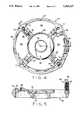
- FIG. 1is a perspective view of a two compartment motor constructed in accordance with the principals of the present invention.
- FIG. 2is a bottom view of the two compartment motor of FIG. 1.
- FIG. 3is a partially exploded view of the motor of FIGS. 1 and 2.
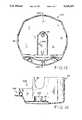
- FIG. 4is a plan view of an end plate for a motor constructed in accordance with the present invention.
- FIG. 5is a cross-sectional view of the end plate of FIG. 4.
- FIG. 6is a plan view of one side of a control plate, without components, constructed in accordance with the principals of the present invention.
- FIG. 7is a plan view of the control plate of FIG. 6 with electrical components mounted thereon.
- FIG. 8is a plan view of the other side of the control plate of FIG. 6.
- FIG. 9is a plan view of the other side of the control plate of FIG. 7.
- FIG. 10is a partial plan view of the control plate of FIG. 7 showing the voltage control switch set in the low position.
- FIG. 11is a cross-sectional view taken along line 11--11 of FIG. 10.
- FIG. 12is a cross-sectional view taken along line 12--12 of FIG. 6.
- FIG. 13is a plan view of the inside of a cover for one compartment of the two compartment motor of the present invention.
- FIG. 14is a cross-sectional view taken along line 14--14 of FIG. 13.
- FIG. 1shows a perspective view of a two compartment motor 10 constructed in accordance with the present invention.
- Motor 10has a first compartment which is defined by a first end shield 12, a second end shield 14 and a generally cylindrical frame 16.
- Frame 16provides support for stator windings (shown in FIG. 3), while end shields 12 and 14 are fitted with bearings to rotatably support an armature assembly within the first compartment adjacent the stator winding, as is well-known in the art.
- Armature shaft 18extends from one end of motor 10 and is threaded, keyed or otherwise adapted for coupling to a load.
- End shield 12is provided with a plurality of mounting lugs 20 which are used to securely mount motor 10 in operating position adjacent the load.
- Motor 10includes a second compartment (which may be referred to as the control compartment) which is generally defined by end shield 14 and a molded plastic cover 22. As discussed in more detail below, the control compartment is used to house a plurality of electrical components used in the control and operation of motor 10. Cover 22 is secured to motor 10, as illustrated in more detail in FIG. 3, by threaded, hex-head screw 24. Electrical access to the control compartment is provided by a conduit receiving opening 26 which is integrally formed in end shield 14.
- FIG. 2is a bottom view of motor 10 in which a plurality of vent openings 28, 30 and 32 are visible. Openings 28, 30 and 32 are integrally formed in a control plate which will be described in detail in connection with FIGS. 6-9 below. Openings 28 and 30 are relatively short, narrow openings which extend from the lateral portions of the bottom of motor 10 to the lower regions of opposing sides of motor 10, as shown in FIG. 1. Openings 32 are relatively long and wide openings which are laterally centered along the bottom of motor 10. This arrangement is intended to provide adequate ventilation and air discharge channels for the motor, while reducing contamination of the two motor compartments with dust and moisture.
- FIG. 3shows an exploded view of motor 10 in which the major components are visible.
- the upper left-hand portion of FIG. 3shows the major components which define the first compartment of two compartment motor 10.
- These componentsinclude end shield 12, frame 16 and end shield 14.
- stator windings 34are supported by frame 16 within the first compartment.
- An armature 36is rotatably supported by end shields 12 and 14 adjacent stator windings 34.
- Armature shaft 18extends from the first compartment through end plate 12 for connection to a load as previously discussed. On the other end of motor 10, shaft 18 extends through end shield 14 into the second compartment defined by cover 22 and end shield 14.
- This end of shaft 18is provided with a slot 38 and wrench flats 40 to facilitate manual rotation of, or to secure against rotation of, armature 36 after the opposing end of shaft 18 is connected to a load.
- Shaft 18is also provided with two circumferential grooves 42 which accept two locking clips 44. Clips 44 secure centrifugal speed switch assembly 46 in position on shaft 18.
- a plurality of electrical conductors 43which are electrically connected to stator windings 34, extend from the first compartment through end plate 14 and terminate in an electrical connector 45.
- control plate 48which, in the embodiment illustrated, is a one-piece molded plastic structure which provides a mounting base for securing a plurality of electrical components used in the control and operation of motor 10 in position within the second compartment.
- Control plate 48is mounted to motor 10 by a pair of long bolts 50 which extend through control plate 48, end shield 14 and frame 16 to engage threads formed in end shield 12.
- An eyelet 51is provided between control plate 48 and end shield 14 (see FIGS. 8 and 9).
- control plate 48can also be secured by nuts threaded onto the ends of bolts which extend through end shield 12, frame 16, end shield 14 and control plate 48.
- Bolts 50along with an additional pair of bolts 52, also serve to secure end shields 12 and 14 to frame 16. In the assembly process, this arrangement allows control plate 48 to be separately mounted to the sub-assembly which includes the first compartment of motor 10. Separate, shorter mounting bolts may also be used to secure control plate 48 to, for instance, threaded holes in end shield 14.
- cover 22mounts, via screw 24 which extends through opening 25, to a threaded screw-receiving boss 54 which is an integrally formed element of control plate 48.
- screw 24is shown separated from cover 22 in the partially exploded view of FIG. 3, screw 24 is preferably "captured" in opening 25 so as to remain with cover 22 upon removal from motor 10.
- both cover plate 48 and cover 22are molded plastic components.
- ground screw 53which threads into an opening in boss 78 of end shield 14 to provide a convenient means by which to connect the metal components of motor 10 to a ground wire (shown in dashed lines) provided by the user.
- FIG. 4is a plan view of end shield 14 of motor 10.
- End shield 14utilizes a "skeleton" design which includes a central portion 60, four radially-extending spokes 62 and a circumferential portion 64. This arrangement provides relatively large openings 66-69 for the passage of ventilating air and power conductors through end shield 14.
- central portion 60 of end shield 14includes a generally circular, annular recess 70 which faces away from armature 36 when end plate 14 is assembled in motor 10. Recess 70 provides clearance for centrifugal switch assembly 46.
- Central portion 60further includes, on the side of end shield 14 which faces the armature, a machined recess 72 which is adapted to receive the bearing (not shown) which supports the respective end of armature 36.
- End shield 14is provided with four holes for receiving mounting bolts 50 and 52. Holes 74, which receive bolts 52, are provided with integrally formed bosses 76 which provide a bearing surface for the heads of bolts 52, and which allow for use of a common bolt length. Mounting holes 77 are formed flush (i.e., without bosses) to provide a flat mating surface for control plate 48. Clearance openings 188 and 202 (FIG. 6) are provided in control plate 48 for bosses 76 and the heads of bolts 52. An additional raised projection or boss 78 is provided as an additional locating and orientation landmark for control plate 48, and provides a grounding point for connecting the metallic elements of motor 10 to a user supplied ground wire (see FIG. 3).
- Openings 80 and 82are provided in an opposing pair of spokes 62 to allow control plate 48 to be mounted directly to end shield 14, independently of bolts 50, if desired. This arrangement allows for the possibility that the motor may be shipped as a "parts" motor without end shield 12.
- Opening 26is integrally formed in an upstanding portion 83 of end shield 14. Opening 26 is threaded to receive a conduit nipple to facilitate connection of the motor to an external power source.
- a recessed shoulder 84is formed around three sides of opening 26 to mate with a similarly shaped cut-out 86 (FIGS. 3 and 14) in cover 22 to provide a step flange-type seal around the three sides of opening 26.
- End shield 14is also provided with a raised projection 87 on the outwardly facing side surface of circumferential portion 64.
- Projection 87extends substantially parallel to the longitudinal axis of motor 10 across substantially the full width of circumferential portion 64 of end shield 14. The function of projection 87 is to provide an alignment and anti-rotation feature for a separately mounted "bonding lug" such as is commonly used in the swimming pool industry.
- end shields 12 and 14are formed in one piece of a metallic material, such as cast aluminum.
- FIGS. 6 and 7show plan views of the exterior side of control plate 48, without and with a plurality of electrical components mounted thereon, respectively.
- the various features of control plate 48 and the componentswill be described with reference to FIGS. 6 and 7, starting at the top or twelve o'clock position, as viewed in the figures, and moving clockwise around the plate.
- Near the top of plate 48is an area 90 for mounting a portion of a centrifugal switch 92.
- Centrifugal switch 92has an actuator portion (210 in FIG. 9) which extends through an opening 94 formed in plate 48.
- Mounting holes 96 and 98are also provided in plate 48 to receive screws 100 and 102 which secure centrifugal switch 92 in position.
- the top surface 104 of centrifugal switch 92is provided with a plurality of slots (e.g., 106), some of which receive male terminals (e.g., 108 and 110). In the embodiment shown in FIG. 7, two of these male terminals are shown connected to female terminals 112 and 114 which, in turn, are connected to electrical conductors 116 and 118, respectively. Openings 99 and 101 are provided in control plate 48, as shown in FIG. 6, to allow conductors such as conductors 116 and 118 to pass through control plate 48, as will be described in additional detail below.
- the base of centrifugal switch 92serves to close and seal lead openings 99 and 101 so that separate seal structures in connection with these openings are not needed.
- An outwardly projecting post 103 and an inwardly (i.e., into area 90) projecting member 105are provided to serve as locating and orienting aids for switch 92.
- centrifugal switch 92Immediately below centrifugal switch 92 is integrally molded boss 54 which, as previously discussed in connection with FIG. 3, receives screw 24 to secure cover 22 in position.
- a pair of reinforcing gussets 120 and 122are integrally molded to provide additional support for boss 54.
- centrifugal switch 92Immediately adjacent centrifugal switch 92 is an opening 124 for one of the two mounting bolts 50. Adjacent opening 124 is a larger opening 126 which provides clearance for boss 78 of end plate 14.
- Adjacent opening 126is a passageway 128.
- Passageway 128is integrally formed in control plate 48 and is aligned, when motor 10 is assembled, with conduit receiving opening 26 of end shield 14.
- Passageway 128provides access to the interior of the control compartment for a plurality of conductors (e.g., 130 and 132) through opening 126.
- Leads 130 and 132terminate in female terminals 134 and 136.
- Female terminals 134 and 136mate with upwardly extending (i.e., out of the page) blade portions of S-shaped terminals 138 and 140, respectively.
- three sets of mounting openingsare provided for the S-shaped terminals.
- Each setincludes a relatively small opening 142 which is sized to receive a rivet, screw or other fastening device 143 to mechanically secure the terminals to control plate 48.
- Each setfurther includes a larger recess 144 to provide clearance for terminal screws, such as screws 146 and 148, which may be used to secure spade terminals or other conductors in electrical contact with the S-shaped terminals.
- each set of mounting openingsincludes a rectangular slot 150 which receives a downwardly extending (i.e., into the drawing) male terminal which extends through control plate 48 for mating with a female terminal on the other side of control plate 48 (see FIG. 9).
- S-shaped terminals 138 and 140include a "lance" portion (not shown) to partially secure them to control plate 48.
- control plate 48In the center of control plate 48 is an opening 152 which provides clearance for armature shaft 18. Immediately adjacent opening 152 is an arcuate shield 154 which extends outwardly from control plate 48 (i.e., out of the drawing in FIGS. 6 and 7) Shield 154, in conjunction with shield 226 of cover 22 (see FIG. 13), serves to shield terminals 134 and 136 and conductors 130 and 132 from rotating armature shaft 18.
- Adjacent passageway 128is a voltage selector switch 156 shown with (FIG. 7) and without (FIG. 6) movable switch portion 158.
- An enlarged, cross-sectional view of switch 156is shown in FIG. 11.
- Switch 156includes an outwardly extending arcuate portion 160 having inwardly and transversely extending lips 162 near the top thereof to prevent or limit complete removal of portion 158 from its position adjacent plate 48.
- a separate arcuate shaped portion 164is formed between the opposing ends of arcuate portion 160 to provide two gaps 166 and 168. Within the circular area defined by arcuate portion 160 and 164 are a plurality of openings 170-174.
- each of the terminals 176receives one end of U-shaped conductors 178 and 180 which are part of movable portion 158.
- conductors 178 and 180connect a first set of terminals 176.
- different pairs of terminals 176are connected.
- the opposite ends of terminals 176extend through plate 48 and are connected, such as by crimping, to electrical conductors illustrated, for example, by conductor 182.
- Switch 156is operated (i.e., moved from the high to low position or vice-versa ⁇ , by grasping upstanding portion 184 of movable portion 158 and pulling portion 158 outwardly to disengage conductors 178 and 180 from terminals 176 until edge portion 186 of portion 158 contacts lips 162. Movable portion 158 is then rotated to the desired position and moved inwardly to engage the ends of U-shaped conductors 178 and 180 into terminals 176.
- This arrangementprovides an easy, convenient and inexpensive mechanism for selecting between high and low voltage settings. If desired, additional switch mechanisms of this type may be provided for, among other things, speed selection.
- Adjacent switch assembly 156is an opening 188 to provide clearance for boss 76 and the head of bolt 52. Also adjacent switch 156 is opening 190. Opening 190 aligns with opening 82 in end shield 14, and provides means by which secondary retention of control plate 48 can be achieved for applications in which end shield 12 is not required.
- vent openings 32Near the bottom (i.e., the six o'clock position) of plate 48 are the plurality of relatively large vent openings 32. These vent openings, in combination with the open "skeletal" construction of end shield 14, ensure adequate ventilation of motor 10. These features further allow for simplified compliance with U.L. standards regarding molten metal protection.
- the integrally formed air channels in control plate 48improve the air intake and discharge capabilities of the motor, resulting in reduced motor operating temperature rises.
- Adjacent vent openings 32is a mounting hole 192 which receives one of the bolts 50 for mounting plate 48 to end shield 14.
- Adjacent mounting hole 192at approximately the nine o'clock position, are a plurality of integrally formed resilient fingers 194 which extend upwardly from control plate 48 (i.e., out of the drawings in FIGS. 6 and 7) which receive and hold starting capacitor 196 in position.
- Additional L-shaped projections 198are also provided to locate capacitor 196 axially within the resilient grip of fingers 194.
- a plurality of molded projections 200serve as stand-offs to laterally position capacitor 196 within the grip of fingers 194.
- Adjacent integrally molded capacitor retaining fingers 194is opening 202 which provides clearance for boss 76 and the head of mounting bolt 52. Adjacent opening 202 is opening 204. Opening 204 aligns with opening 80 in end shield 14 to provide an alternative means for securing control plate 48 to end shield 14.
- FIGS. 8 and 9show, respectively, the interior or back side of control plate 48.
- the features of the back side of plate 48will be discussed beginning at the top or twelve o'clock position and moving counterclockwise around the circumference of plate 48.
- FIGS. 6 and 7show unchanged in FIGS. 8 and 9 (for example, mounting holes 96 and 98, openings 124 and 126, etc.), such features are identified with like reference numbers in all figures, but are not separately discussed below.
- a recessis provided near the top of control plate 48 to accommodate a multi-terminal electrical connector 206 which is configured to mate with electrical connector 45 (FIG. 3) which, in turn, is connected to conductors 43 which extend into the first or motor compartment of motor 10.
- Connector 206is connected to a plurality of electrical conductors which, in turn, are connected to various ones of the electrical components mounted on control plate 48, including one or more of the conductors extending through opening 99. Conductors may also extend through opening 101 which is located on the opposite side of open area 205.
- Electrical connectors 45 and 206allow the electrical components on control plate 48 to be conveniently and reliably connected to the other major components (e.g., stator windings 34) of motor 10 in a single operation to improve the quality and manufacturability of the motor.
- annular wall 208Inwardly of recess 205 and opening 94 is an annular wall 208 which extends 360° around an inner circumference of plate 48. The inner surface of wall 208 defines a protected space for centrifugal speed switch assembly 46. Extending into this space through a portion of opening 94 is actuator 210 which interacts with a rotating portion of switch 46 to open or close an electrical circuit, via centrifugal switch 92, when armature 36 reaches a specified rotational speed.
- Adjacent recess 205is opening 124 for one of the two mounting bolts 50. Both opening 124 and diagonally-disposed opening 192 are countersunk, as illustrated in FIG. 8, to receive metal eyelets 51 as illustrated in FIG. 9. Eyelets 51 better distribute the stresses placed upon control plate 48 by the heads of bolts 50.
- opening 142 and recess 144 and slots 150Inwardly of and on either side of surface 129 are opening 142 and recess 144 and slots 150 which were discussed in connection with FIGS. 6 and 7.
- Female terminals 212 and 214are shown connected to the male ends (which are hidden from view by the female terminals) of S-shaped terminals 138 and 140.
- Fasteners (i.e., rivets) 143are visible in FIG. 9.
- Adjacent surface 129, and inwardly of vent openings 28,is the portion of switch 156 which is integrally formed With control plate 48.
- Switch 156was previously discussed in connection with FIGS. 6, 7, 10 and 11 above.
- Adjacent switch 156are openings 188 and 190, vent openings 32, opening 192 and vent openings 30, all of which have been previously discussed and will not be separately discussed in connection with FIGS. 8 and 9.
- a space 216which is provided for mounting a thermal overload device 218 to control plate 48.
- An integrally formed post 219 and a boss 220 with an opening 222 for receiving a fastener 224are provided for mounting thermal overload 218.
- post 219 and boss 220are preferably molded of a plastic material to provide a one-piece, completely integrated structure.
- FIG. 12is a cross-sectional view of control plate 48 taken along line 12--12 of FIG. 6. Visible in FIG. 12 is upstanding arcuate portion 160. Portion 164 is shown in dashed lines. As is apparent in FIG. 12, portion 164 is substantially shorter than portion 160 to provide clearance for "pointer" 169 which extends somewhat from movable portion 158 beyond the inner perimeter of the arcuate portions to more clearly indicate the switch position. Also visible is shield 154 and boss 54 with opening 55 for receiving screw 24. Adjacent boss 54 is space 90 which receives centrifugal switch 92. Opposing space 90 is recess 205 which, as discussed above, is provided to receive electrical connectors 45 and 206. Finally, recess 208 which defines clearance space for centrifugal switch 46 is clearly shown in FIG. 12, as is opening 94 which provides clearance for actuator 210.
- FIG. 13shows an interior view of cover 22.
- cover 22Integrally molded in the interior of cover 22 is an additional shield 226 which cooperates with shield 154 to protect terminals, wiring and other electrical components from the exposed end of rotating armature shaft 18.
- the exterior contours of cover 22 in the areas generally designated by reference numerals 228 and 230are molded to fit around and form a relatively tight seal with vent openings 28, 30 and 32. Cut-out 86, as previously discussed, conforms to recessed shoulder 84 of end shield 14.
- cover 22in the embodiment illustrated, is molded from a plastic material.
- the arrangement of the present inventionallows for efficient assembly of a high-quality two compartment motor.
- the electrical components referred to abovesuch as the thermal overload, the capacitor, the voltage selection switch, the actuator for the centrifugal switch, and the terminals and wiring are preassembled "off-line" with strict quality controls in a uniform and repeatable fashion.
- the parts of the motor which make up and are enclosed in the first compartmentmay be assembled in a standard manner, with "skeleton" end shield 14 mounted to allow conductors 43 to extend through the open portions of the end shield.
- the rotatable portion of a centrifugal switchmay be mounted to the armature, if appropriate.
- the preassembled control boardis then brought to the motor and electrical connectors 45 and 206 are connected in a single operation.
- the control board assemblyis secured to either end shield or the frame. Cover 22 is then positioned and secured, such as by screw 24, to complete the assembly.
Landscapes
- Engineering & Computer Science (AREA)
- Power Engineering (AREA)
- Microelectronics & Electronic Packaging (AREA)
- Motor Or Generator Frames (AREA)
- Motor Or Generator Cooling System (AREA)
Abstract
Description
Claims (29)
Priority Applications (5)
| Application Number | Priority Date | Filing Date | Title |
|---|---|---|---|
| US07/854,337US5245237A (en) | 1992-03-19 | 1992-03-19 | Two compartment motor |
| CA002089298ACA2089298C (en) | 1992-03-19 | 1993-02-11 | Two compartment motor and method of manufacturing same |
| EP93301939AEP0561587B1 (en) | 1992-03-19 | 1993-03-15 | Two compartment motor and method of manufacturing same |
| DE69329956TDE69329956T2 (en) | 1992-03-19 | 1993-03-15 | Dual compartment engine and method of making the same |
| US08/070,014US5430931A (en) | 1992-03-19 | 1993-05-28 | Method of manufacturing a two compartment motor |
Applications Claiming Priority (1)
| Application Number | Priority Date | Filing Date | Title |
|---|---|---|---|
| US07/854,337US5245237A (en) | 1992-03-19 | 1992-03-19 | Two compartment motor |
Related Child Applications (1)
| Application Number | Title | Priority Date | Filing Date |
|---|---|---|---|
| US08/070,014DivisionUS5430931A (en) | 1992-03-19 | 1993-05-28 | Method of manufacturing a two compartment motor |
Publications (1)
| Publication Number | Publication Date |
|---|---|
| US5245237Atrue US5245237A (en) | 1993-09-14 |
Family
ID=25318410
Family Applications (2)
| Application Number | Title | Priority Date | Filing Date |
|---|---|---|---|
| US07/854,337Expired - LifetimeUS5245237A (en) | 1992-03-19 | 1992-03-19 | Two compartment motor |
| US08/070,014Expired - LifetimeUS5430931A (en) | 1992-03-19 | 1993-05-28 | Method of manufacturing a two compartment motor |
Family Applications After (1)
| Application Number | Title | Priority Date | Filing Date |
|---|---|---|---|
| US08/070,014Expired - LifetimeUS5430931A (en) | 1992-03-19 | 1993-05-28 | Method of manufacturing a two compartment motor |
Country Status (4)
| Country | Link |
|---|---|
| US (2) | US5245237A (en) |
| EP (1) | EP0561587B1 (en) |
| CA (1) | CA2089298C (en) |
| DE (1) | DE69329956T2 (en) |
Cited By (35)
| Publication number | Priority date | Publication date | Assignee | Title |
|---|---|---|---|---|
| US5357161A (en)* | 1993-09-09 | 1994-10-18 | Emerson Electric Co. | Motor enclosure |
| US5386164A (en)* | 1993-01-19 | 1995-01-31 | General Electric Company | Motor assembly with removable lead guard |
| US5493158A (en)* | 1993-10-04 | 1996-02-20 | Emerson Electric Co. | Motor capacitor bracket |
| US5723924A (en)* | 1995-02-08 | 1998-03-03 | Valeo Systemes D'essuyage | Motorized reduction gear unit, especially for driving a vehicle screen wiper apparatus |
| US5886439A (en)* | 1995-12-07 | 1999-03-23 | Brother Kogyo Kabushiki Kaisha | Motor unit having drive motor and controller |
| US6057615A (en)* | 1999-07-30 | 2000-05-02 | A. O. Smith Corporation | Bracket to attach a capacitor to a motor housing |
| US6107708A (en)* | 1998-03-16 | 2000-08-22 | Asmo, Co., Ltd. | Brushless motor |
| US6133658A (en)* | 1998-01-27 | 2000-10-17 | General Electric Company | Method of voltage selection and bearing protection for an electric motor |
| US6191512B1 (en)* | 1998-03-26 | 2001-02-20 | Meritor Light Vehicle Systems-France | Electric motor for actuating a functional unit of a vehicle |
| US6215214B1 (en) | 1998-04-24 | 2001-04-10 | General Electric Company | Shaft support assembly for direct drive motor |
| US20020140304A1 (en)* | 2001-03-27 | 2002-10-03 | Dreher Lincoln J. | Case retained external capacitor |
| US6589018B2 (en) | 2001-08-14 | 2003-07-08 | Lakewood Engineering And Manufacturing Co. | Electric fan motor assembly with motor housing control switch and electrical input socket |
| US6657338B2 (en) | 2001-11-29 | 2003-12-02 | General Electric Company | Two compartment motor |
| US20040017120A1 (en)* | 2002-07-24 | 2004-01-29 | Lyle David M. | Three phase electric motor terminal box mounted connection board |
| US20040051412A1 (en)* | 2002-07-10 | 2004-03-18 | Moteurs Leroy Somer | Alternator |
| US20040195923A1 (en)* | 2003-04-01 | 2004-10-07 | A.O. Smith Corporation | Electric motor having a terminal board |
| US6831382B1 (en)* | 2004-03-17 | 2004-12-14 | Emerson Electric Co. | Cover for electric motor |
| US20050082921A1 (en)* | 2003-10-16 | 2005-04-21 | A.O. Smith Corporation | Electric machine and method of assembling the same |
| US20060181167A1 (en)* | 2005-02-11 | 2006-08-17 | Bradfield Michael D | Method and apparatus for attachment of a cover for a dynamoelectric machine |
| US20070081345A1 (en)* | 2005-08-03 | 2007-04-12 | Ruud Lighting, Inc. | Industrial light fixture with spring-bracket over capacitor |
| US20080179979A1 (en)* | 2007-01-26 | 2008-07-31 | A. O. Smith Corporation | Motor end frame assembly and motor incorporating the same |
| US20100001598A1 (en)* | 2008-07-07 | 2010-01-07 | A. O. Smith Corporation | External voltage change device |
| US20110031830A1 (en)* | 2009-08-10 | 2011-02-10 | Stainless Motors, Inc. | Electric motor for use in hazardous environments |
| US20120313468A1 (en)* | 2011-06-10 | 2012-12-13 | Nidec Motor Corporation | Motor endshield with capacitor retention structure |
| CN103733485A (en)* | 2011-07-11 | 2014-04-16 | 斯佩尔汽车有限公司 | Rotating electric machine and related packaging method |
| US8745847B2 (en) | 2011-11-17 | 2014-06-10 | Remy Technologies, L.L.C. | Method of P-forming a continuous conductor having a rectangular cross section and a stator including a stator winding formed from a P-formed conductor having a rectangular cross-section |
| US8789259B2 (en) | 2011-11-17 | 2014-07-29 | Remy Technologies, L.L.C. | Method of winding a stator core with a continuous conductor having a rectangular cross-section and a stator core |
| US20150076941A1 (en)* | 2011-10-31 | 2015-03-19 | Regal Beloit America, Inc. | Methods and apparatus for mounting a motor controller on a stator assembly |
| US20150090212A1 (en)* | 2011-11-18 | 2015-04-02 | Valeo Equipements Electriques Moteur | Electric starter with integrated electronic filter for internal combustion engine |
| US20150308528A1 (en)* | 2014-03-21 | 2015-10-29 | IMS Gear GbmH | Actuator arrangement |
| US9467010B2 (en) | 2011-11-17 | 2016-10-11 | Remy Technologies, L.L.C. | Method of winding a stator core with a continuous conductor having a rectangular cross-section and a stator core |
| US20170214157A1 (en)* | 2016-01-27 | 2017-07-27 | Kabushiki Kaisha Tokai Rika Denki Seisakusho | Insulator |
| US9993926B2 (en)* | 2015-06-01 | 2018-06-12 | Xyzprinting, Inc. | Joint structure |
| USD969744S1 (en) | 2021-02-25 | 2022-11-15 | Regal Beloit America, Inc. | Motor housing with electronics housing |
| US20230035697A1 (en)* | 2020-01-02 | 2023-02-02 | Lg Innotek Co., Ltd. | Motor |
Families Citing this family (29)
| Publication number | Priority date | Publication date | Assignee | Title |
|---|---|---|---|---|
| JPH07245904A (en)* | 1994-03-07 | 1995-09-19 | Asmo Co Ltd | Terminal block for motor |
| US5872411A (en)* | 1994-03-07 | 1999-02-16 | Asmo Co., Ltd. | Motor terminal device |
| DE19509130A1 (en)* | 1994-03-14 | 1995-09-21 | Fuji Electric Co Ltd | Servomotor of compact design with reduced axial length |
| US5532534A (en)* | 1994-05-11 | 1996-07-02 | Emerson Electric Co. | Brushless permanent magnet condenser motor for refrigeration |
| US5663604A (en)* | 1994-12-28 | 1997-09-02 | Nidec Corporation | Brushless motor |
| DE19511114C1 (en)* | 1995-03-25 | 1996-08-29 | Grundfos As | Electric motor |
| US5821649A (en)* | 1995-08-18 | 1998-10-13 | Magnetek, Inc. | Electrostatic shielding system for reduction of bearing currents in electric motors |
| DE29516656U1 (en)* | 1995-10-21 | 1995-12-07 | Ebm Elektrobau Mulfingen Gmbh & Co, 74673 Mulfingen | Brushless electric motor |
| US5767596A (en)* | 1996-10-03 | 1998-06-16 | General Electric Company | Dynamoelectric machine and processes for making the same |
| US5872410A (en)* | 1996-10-18 | 1999-02-16 | Reliance Electric Industrial Company | Motor terminal and capacitor box |
| AU5669999A (en) | 1998-09-04 | 2000-03-27 | Emerson Electric Co. | Reduced size electromagnetic device |
| US6204582B1 (en)* | 1999-12-16 | 2001-03-20 | Eaton Corporation | Servo motor assembly and method of making same |
| US6380645B1 (en)* | 2000-05-11 | 2002-04-30 | General Electric Company | Cast motor end shield including insert and method for casting |
| US6380648B1 (en)* | 2001-06-11 | 2002-04-30 | Chun-Pu Hsu | Wheel drum structure of inner stator portion with inbuilt switches |
| GB2422965B (en)* | 2002-02-04 | 2006-11-08 | Milwaukee Electric Tool Corp | Electrical devices including a switched reluctance motor |
| US6674199B2 (en)* | 2002-04-15 | 2004-01-06 | A. O. Smith Corporation | Electric motor housing |
| JP4111053B2 (en)* | 2003-05-16 | 2008-07-02 | 株式会社デンソー | Starter |
| US7256522B2 (en)* | 2005-05-31 | 2007-08-14 | Regal-Beloit Corporation | Motor control packaging for an electric motor |
| US7420302B2 (en)* | 2005-05-31 | 2008-09-02 | Regal-Beloit Corporation | Mid shield bearing support of an electric motor |
| US20070063603A1 (en)* | 2005-08-22 | 2007-03-22 | Levine Gregory M | Integrated motor and controller assemblies for horizontal axis washing machines |
| DE102007021491A1 (en)* | 2007-05-08 | 2008-11-13 | Robert Bosch Gmbh | Motor arrangement with electronic isolating relay module |
| MX2011010884A (en)* | 2009-04-16 | 2012-01-19 | Zhongshan Broad Ocean Motor | Motor. |
| CN201393145Y (en)* | 2009-04-16 | 2010-01-27 | 中山大洋电机股份有限公司 | Electric machine |
| US8502436B2 (en) | 2011-02-14 | 2013-08-06 | Regal Beloit America, Inc. | Electric motor having an end frame |
| US9970434B2 (en) | 2015-05-17 | 2018-05-15 | Regal Beloit America, Inc. | Motor, controller and associated method |
| US10603777B2 (en)* | 2015-10-30 | 2020-03-31 | Black & Decker Inc. | Control and power module for driving a brushless motor in a power tool |
| JP6714162B2 (en)* | 2017-07-18 | 2020-06-24 | 三菱電機株式会社 | Electric motor and ventilation fan |
| CN110545001B (en)* | 2019-10-15 | 2022-07-01 | 林国尊 | Ceiling fan motor outer cover |
| DE102020204357A1 (en) | 2020-04-03 | 2021-10-07 | Siemens Aktiengesellschaft | Drive device and housing for a drive device |
Citations (41)
| Publication number | Priority date | Publication date | Assignee | Title |
|---|---|---|---|---|
| US1857202A (en)* | 1929-06-29 | 1932-05-10 | Lee Engineering Res Corp | Electric motor |
| US2556675A (en)* | 1942-10-07 | 1951-06-12 | Borg Warner | Control system |
| US2616682A (en)* | 1949-02-01 | 1952-11-04 | Greenhut Joseph | Centrifugal speed responsive device with spring support |
| US2683844A (en)* | 1951-08-24 | 1954-07-13 | Edward J Schaefer | Reversing switch for electric motors |
| US2768260A (en)* | 1953-04-02 | 1956-10-23 | Greenhut Joseph | Constant-load spring-loaded stationary starting switch for electric motors |
| US2772894A (en)* | 1954-08-25 | 1956-12-04 | William K Oats | Fifth wheel stop for tractor trailers |
| US2774894A (en)* | 1953-07-13 | 1956-12-18 | Gen Motors Corp | Connector for an electric motor |
| US2777912A (en)* | 1954-05-21 | 1957-01-15 | Smith Corp A O | Adjustable centrifugal switch assembly |
| US2811656A (en)* | 1956-10-31 | 1957-10-29 | Gen Electric | Combination fan and centrifugal mechanism for electric motor |
| US2831153A (en)* | 1956-11-19 | 1958-04-15 | Alliance Mfg Co | Centrifugal switch mechanism |
| US2846540A (en)* | 1954-12-06 | 1958-08-05 | Electric Specialty Company | Centrifugal electrical circuit interrupting device |
| CA618492A (en)* | 1961-04-18 | Westinghouse Electric Corporation | Terminal board for dynamoelectric machine | |
| GB1016119A (en)* | 1963-10-16 | 1966-01-05 | Tokyo Kagaku Kabushiki Kaisha | Electric motor |
| US3315139A (en)* | 1963-11-18 | 1967-04-18 | Safety Electrical Equipment Co | Centrifugal overspeed switch for electric motors |
| US3482128A (en)* | 1967-05-08 | 1969-12-02 | Gen Electric | Dynamoelectric machine having a versatile electrical circuit-making unit |
| US3571541A (en)* | 1969-02-17 | 1971-03-23 | Cherry Electrical Prod | Snap action switch |
| US3575562A (en)* | 1969-09-24 | 1971-04-20 | Gen Motors Corp | Centrifugal switch assembly for a motor starting circuit |
| US3582741A (en)* | 1969-01-28 | 1971-06-01 | Emerson Electric Co | Brake system for electrical motors |
| US3707637A (en)* | 1971-04-28 | 1972-12-26 | Westinghouse Electric Corp | Dynamoelectric machine with lint guard for terminals |
| US4038574A (en)* | 1975-06-18 | 1977-07-26 | Emerson Electric Co. | Motor lead guide and lead wire attaching means |
| JPS54122804A (en)* | 1978-03-17 | 1979-09-22 | Hitachi Ltd | Wiring base board |
| JPS54137601A (en)* | 1978-04-19 | 1979-10-25 | Hitachi Ltd | Induction motor stator |
| US4206959A (en)* | 1978-03-27 | 1980-06-10 | Emerson Electric Co. | Terminal board with integral insulated pocket |
| US4296366A (en)* | 1979-10-09 | 1981-10-20 | Emerson Electric Co. | Motor starting switch |
| US4315118A (en)* | 1979-08-09 | 1982-02-09 | Robert Bosch Gmbh | Electric centrifugal switch |
| US4386290A (en)* | 1981-04-30 | 1983-05-31 | Marathon Electric Manufacturing Corp. | Centrifugal actuator for A.C. induction motor |
| US4394553A (en)* | 1981-04-23 | 1983-07-19 | Amf Incorporated | Snap action switch |
| US4414443A (en)* | 1981-10-28 | 1983-11-08 | Emerson Electric Co. | Environmentally protected switch construction |
| US4513214A (en)* | 1983-10-03 | 1985-04-23 | Allied Corporation | Dynamoelectric machine |
| US4569125A (en)* | 1982-10-21 | 1986-02-11 | Black & Decker Inc. | Wiring arrangement for an electric tool |
| US4593163A (en)* | 1983-08-12 | 1986-06-03 | General Electric Company | Electric motors and method of manufacturing and operating same |
| US4594773A (en)* | 1983-05-20 | 1986-06-17 | General Electric Company | Method of assembling a switch and terminal assembly to an end frame for a dynamoelectric machine |
| US4616149A (en)* | 1983-09-28 | 1986-10-07 | Ebm Elektrobau Mulfingen Gmbh & Co. | Arrangement for joining the cable ends of a stator winding of electric motors by means of a connector |
| US4658196A (en)* | 1985-10-16 | 1987-04-14 | Emerson Electric Co. | Electric motor starting switch assembly |
| US4665286A (en)* | 1986-03-03 | 1987-05-12 | Emerson Electric Co. | Motor starting and automatic reversing switch |
| US4668898A (en)* | 1986-04-21 | 1987-05-26 | General Electric Company | Electronically commutated motor |
| US4670631A (en)* | 1986-02-20 | 1987-06-02 | Emerson Electric Co. | Modified switch assembly for electrical machinery |
| US4686401A (en)* | 1986-01-21 | 1987-08-11 | Emerson Electric Co. | Switch assembly for electrical machinery |
| US4883982A (en)* | 1988-06-02 | 1989-11-28 | General Electric Company | Electronically commutated motor, blower integral therewith, and stationary and rotatable assemblies therefor |
| US5006744A (en)* | 1988-12-27 | 1991-04-09 | General Electric Company | Integrated electronically commutated motor and control circuit assembly |
| US5068555A (en)* | 1989-08-26 | 1991-11-26 | Oberdorfer Boegel Rainer | Dust exhauster for a vacuum cleaner having improved cooling |
Family Cites Families (5)
| Publication number | Priority date | Publication date | Assignee | Title |
|---|---|---|---|---|
| US4426770A (en)* | 1978-03-06 | 1984-01-24 | General Electric Company | Method of assembling a switch and terminal assembly and mounting it to a dynamoelectric machine |
| JPS6098838A (en)* | 1983-11-04 | 1985-06-01 | Yaskawa Electric Mfg Co Ltd | motor |
| DE3815427C3 (en)* | 1987-05-08 | 1995-08-31 | Lutz Pumpen Gmbh & Co Kg | Electric motor, in particular drive motor for a drum or container pump |
| DE3805060A1 (en)* | 1988-02-18 | 1989-08-31 | Miele & Cie | Electric motor having a system carrier for accommodating components, conductor tracks and control and regulation modules (chips) |
| US5127148A (en)* | 1989-10-26 | 1992-07-07 | A. O. Smith Corporation | Method of fabricating a dynameoelectric machine |
- 1992
- 1992-03-19USUS07/854,337patent/US5245237A/ennot_activeExpired - Lifetime
- 1993
- 1993-02-11CACA002089298Apatent/CA2089298C/ennot_activeExpired - Lifetime
- 1993-03-15DEDE69329956Tpatent/DE69329956T2/ennot_activeExpired - Fee Related
- 1993-03-15EPEP93301939Apatent/EP0561587B1/ennot_activeExpired - Lifetime
- 1993-05-28USUS08/070,014patent/US5430931A/ennot_activeExpired - Lifetime
Patent Citations (41)
| Publication number | Priority date | Publication date | Assignee | Title |
|---|---|---|---|---|
| CA618492A (en)* | 1961-04-18 | Westinghouse Electric Corporation | Terminal board for dynamoelectric machine | |
| US1857202A (en)* | 1929-06-29 | 1932-05-10 | Lee Engineering Res Corp | Electric motor |
| US2556675A (en)* | 1942-10-07 | 1951-06-12 | Borg Warner | Control system |
| US2616682A (en)* | 1949-02-01 | 1952-11-04 | Greenhut Joseph | Centrifugal speed responsive device with spring support |
| US2683844A (en)* | 1951-08-24 | 1954-07-13 | Edward J Schaefer | Reversing switch for electric motors |
| US2768260A (en)* | 1953-04-02 | 1956-10-23 | Greenhut Joseph | Constant-load spring-loaded stationary starting switch for electric motors |
| US2774894A (en)* | 1953-07-13 | 1956-12-18 | Gen Motors Corp | Connector for an electric motor |
| US2777912A (en)* | 1954-05-21 | 1957-01-15 | Smith Corp A O | Adjustable centrifugal switch assembly |
| US2772894A (en)* | 1954-08-25 | 1956-12-04 | William K Oats | Fifth wheel stop for tractor trailers |
| US2846540A (en)* | 1954-12-06 | 1958-08-05 | Electric Specialty Company | Centrifugal electrical circuit interrupting device |
| US2811656A (en)* | 1956-10-31 | 1957-10-29 | Gen Electric | Combination fan and centrifugal mechanism for electric motor |
| US2831153A (en)* | 1956-11-19 | 1958-04-15 | Alliance Mfg Co | Centrifugal switch mechanism |
| GB1016119A (en)* | 1963-10-16 | 1966-01-05 | Tokyo Kagaku Kabushiki Kaisha | Electric motor |
| US3315139A (en)* | 1963-11-18 | 1967-04-18 | Safety Electrical Equipment Co | Centrifugal overspeed switch for electric motors |
| US3482128A (en)* | 1967-05-08 | 1969-12-02 | Gen Electric | Dynamoelectric machine having a versatile electrical circuit-making unit |
| US3582741A (en)* | 1969-01-28 | 1971-06-01 | Emerson Electric Co | Brake system for electrical motors |
| US3571541A (en)* | 1969-02-17 | 1971-03-23 | Cherry Electrical Prod | Snap action switch |
| US3575562A (en)* | 1969-09-24 | 1971-04-20 | Gen Motors Corp | Centrifugal switch assembly for a motor starting circuit |
| US3707637A (en)* | 1971-04-28 | 1972-12-26 | Westinghouse Electric Corp | Dynamoelectric machine with lint guard for terminals |
| US4038574A (en)* | 1975-06-18 | 1977-07-26 | Emerson Electric Co. | Motor lead guide and lead wire attaching means |
| JPS54122804A (en)* | 1978-03-17 | 1979-09-22 | Hitachi Ltd | Wiring base board |
| US4206959A (en)* | 1978-03-27 | 1980-06-10 | Emerson Electric Co. | Terminal board with integral insulated pocket |
| JPS54137601A (en)* | 1978-04-19 | 1979-10-25 | Hitachi Ltd | Induction motor stator |
| US4315118A (en)* | 1979-08-09 | 1982-02-09 | Robert Bosch Gmbh | Electric centrifugal switch |
| US4296366A (en)* | 1979-10-09 | 1981-10-20 | Emerson Electric Co. | Motor starting switch |
| US4394553A (en)* | 1981-04-23 | 1983-07-19 | Amf Incorporated | Snap action switch |
| US4386290A (en)* | 1981-04-30 | 1983-05-31 | Marathon Electric Manufacturing Corp. | Centrifugal actuator for A.C. induction motor |
| US4414443A (en)* | 1981-10-28 | 1983-11-08 | Emerson Electric Co. | Environmentally protected switch construction |
| US4569125A (en)* | 1982-10-21 | 1986-02-11 | Black & Decker Inc. | Wiring arrangement for an electric tool |
| US4594773A (en)* | 1983-05-20 | 1986-06-17 | General Electric Company | Method of assembling a switch and terminal assembly to an end frame for a dynamoelectric machine |
| US4593163A (en)* | 1983-08-12 | 1986-06-03 | General Electric Company | Electric motors and method of manufacturing and operating same |
| US4616149A (en)* | 1983-09-28 | 1986-10-07 | Ebm Elektrobau Mulfingen Gmbh & Co. | Arrangement for joining the cable ends of a stator winding of electric motors by means of a connector |
| US4513214A (en)* | 1983-10-03 | 1985-04-23 | Allied Corporation | Dynamoelectric machine |
| US4658196A (en)* | 1985-10-16 | 1987-04-14 | Emerson Electric Co. | Electric motor starting switch assembly |
| US4686401A (en)* | 1986-01-21 | 1987-08-11 | Emerson Electric Co. | Switch assembly for electrical machinery |
| US4670631A (en)* | 1986-02-20 | 1987-06-02 | Emerson Electric Co. | Modified switch assembly for electrical machinery |
| US4665286A (en)* | 1986-03-03 | 1987-05-12 | Emerson Electric Co. | Motor starting and automatic reversing switch |
| US4668898A (en)* | 1986-04-21 | 1987-05-26 | General Electric Company | Electronically commutated motor |
| US4883982A (en)* | 1988-06-02 | 1989-11-28 | General Electric Company | Electronically commutated motor, blower integral therewith, and stationary and rotatable assemblies therefor |
| US5006744A (en)* | 1988-12-27 | 1991-04-09 | General Electric Company | Integrated electronically commutated motor and control circuit assembly |
| US5068555A (en)* | 1989-08-26 | 1991-11-26 | Oberdorfer Boegel Rainer | Dust exhauster for a vacuum cleaner having improved cooling |
Cited By (53)
| Publication number | Priority date | Publication date | Assignee | Title |
|---|---|---|---|---|
| US5386164A (en)* | 1993-01-19 | 1995-01-31 | General Electric Company | Motor assembly with removable lead guard |
| US5357161A (en)* | 1993-09-09 | 1994-10-18 | Emerson Electric Co. | Motor enclosure |
| US5493158A (en)* | 1993-10-04 | 1996-02-20 | Emerson Electric Co. | Motor capacitor bracket |
| US5723924A (en)* | 1995-02-08 | 1998-03-03 | Valeo Systemes D'essuyage | Motorized reduction gear unit, especially for driving a vehicle screen wiper apparatus |
| CN1064185C (en)* | 1995-12-07 | 2001-04-04 | 兄弟工业株式会社 | motor assembly |
| US5886439A (en)* | 1995-12-07 | 1999-03-23 | Brother Kogyo Kabushiki Kaisha | Motor unit having drive motor and controller |
| US6133658A (en)* | 1998-01-27 | 2000-10-17 | General Electric Company | Method of voltage selection and bearing protection for an electric motor |
| US6107708A (en)* | 1998-03-16 | 2000-08-22 | Asmo, Co., Ltd. | Brushless motor |
| US6191512B1 (en)* | 1998-03-26 | 2001-02-20 | Meritor Light Vehicle Systems-France | Electric motor for actuating a functional unit of a vehicle |
| US6215214B1 (en) | 1998-04-24 | 2001-04-10 | General Electric Company | Shaft support assembly for direct drive motor |
| US6057615A (en)* | 1999-07-30 | 2000-05-02 | A. O. Smith Corporation | Bracket to attach a capacitor to a motor housing |
| US6717307B2 (en)* | 2001-03-27 | 2004-04-06 | Fasco Industries, Inc. | Case retained external capacitor |
| US20020140304A1 (en)* | 2001-03-27 | 2002-10-03 | Dreher Lincoln J. | Case retained external capacitor |
| US6589018B2 (en) | 2001-08-14 | 2003-07-08 | Lakewood Engineering And Manufacturing Co. | Electric fan motor assembly with motor housing control switch and electrical input socket |
| US6887049B2 (en) | 2001-08-14 | 2005-05-03 | Lakewood Engineering And Manufacturing Co. | Electric fan motor assembly |
| US6657338B2 (en) | 2001-11-29 | 2003-12-02 | General Electric Company | Two compartment motor |
| US20040051412A1 (en)* | 2002-07-10 | 2004-03-18 | Moteurs Leroy Somer | Alternator |
| US20040017120A1 (en)* | 2002-07-24 | 2004-01-29 | Lyle David M. | Three phase electric motor terminal box mounted connection board |
| US6856056B2 (en)* | 2002-07-24 | 2005-02-15 | Emerson Electric Co. | Three phase electric motor terminal box mounted connection board |
| US20040195923A1 (en)* | 2003-04-01 | 2004-10-07 | A.O. Smith Corporation | Electric motor having a terminal board |
| US6882070B2 (en) | 2003-04-01 | 2005-04-19 | A. O. Smith Corporation | Electric motor having a terminal board |
| US20050082921A1 (en)* | 2003-10-16 | 2005-04-21 | A.O. Smith Corporation | Electric machine and method of assembling the same |
| US6933640B2 (en) | 2003-10-16 | 2005-08-23 | A.O. Smith Corporation | Electric machine and method of assembling the same |
| US6831382B1 (en)* | 2004-03-17 | 2004-12-14 | Emerson Electric Co. | Cover for electric motor |
| US20060181167A1 (en)* | 2005-02-11 | 2006-08-17 | Bradfield Michael D | Method and apparatus for attachment of a cover for a dynamoelectric machine |
| US7345391B2 (en)* | 2005-02-11 | 2008-03-18 | Remy International, Inc. | Method and apparatus for attachment of a cover for a dynamoelectric machine |
| US20070081345A1 (en)* | 2005-08-03 | 2007-04-12 | Ruud Lighting, Inc. | Industrial light fixture with spring-bracket over capacitor |
| US7319593B2 (en) | 2005-08-03 | 2008-01-15 | Ruud Lighting, Inc. | Industrial light fixture with spring-bracket over capacitor |
| US20080179979A1 (en)* | 2007-01-26 | 2008-07-31 | A. O. Smith Corporation | Motor end frame assembly and motor incorporating the same |
| US7791234B2 (en)* | 2007-01-26 | 2010-09-07 | A. O. Smith Corporation | Motor end frame assembly and motor incorporating the same |
| US20100001598A1 (en)* | 2008-07-07 | 2010-01-07 | A. O. Smith Corporation | External voltage change device |
| US7898131B2 (en) | 2008-07-07 | 2011-03-01 | A.O. Smith Corporation | External voltage change device |
| US20110031830A1 (en)* | 2009-08-10 | 2011-02-10 | Stainless Motors, Inc. | Electric motor for use in hazardous environments |
| US8227947B2 (en)* | 2009-08-10 | 2012-07-24 | Stainless Motors, Inc. | Electric motor for use in hazardous environments |
| US20120313468A1 (en)* | 2011-06-10 | 2012-12-13 | Nidec Motor Corporation | Motor endshield with capacitor retention structure |
| US8587169B2 (en)* | 2011-06-10 | 2013-11-19 | Nidec Motor Corporation | Motor endshield with capacitor retention structure |
| CN103733485A (en)* | 2011-07-11 | 2014-04-16 | 斯佩尔汽车有限公司 | Rotating electric machine and related packaging method |
| CN103733485B (en)* | 2011-07-11 | 2017-03-01 | 斯佩尔汽车有限公司 | Rotating electrical machines and related packaging methods |
| US20150076941A1 (en)* | 2011-10-31 | 2015-03-19 | Regal Beloit America, Inc. | Methods and apparatus for mounting a motor controller on a stator assembly |
| US10122236B2 (en)* | 2011-10-31 | 2018-11-06 | Regal Beloit America, Inc. | Methods and apparatus for mounting a motor controller on a stator assembly |
| US8789259B2 (en) | 2011-11-17 | 2014-07-29 | Remy Technologies, L.L.C. | Method of winding a stator core with a continuous conductor having a rectangular cross-section and a stator core |
| US9467010B2 (en) | 2011-11-17 | 2016-10-11 | Remy Technologies, L.L.C. | Method of winding a stator core with a continuous conductor having a rectangular cross-section and a stator core |
| US8745847B2 (en) | 2011-11-17 | 2014-06-10 | Remy Technologies, L.L.C. | Method of P-forming a continuous conductor having a rectangular cross section and a stator including a stator winding formed from a P-formed conductor having a rectangular cross-section |
| US20150090212A1 (en)* | 2011-11-18 | 2015-04-02 | Valeo Equipements Electriques Moteur | Electric starter with integrated electronic filter for internal combustion engine |
| US9605640B2 (en)* | 2011-11-18 | 2017-03-28 | Valeo Equipements Electriques Moteur | Electric starter with integrated electronic filter for internal combustion engine |
| US10180168B2 (en)* | 2014-03-21 | 2019-01-15 | Ims Gear Se & Co. Kgaa | Actuator arrangement |
| US20150308528A1 (en)* | 2014-03-21 | 2015-10-29 | IMS Gear GbmH | Actuator arrangement |
| US9993926B2 (en)* | 2015-06-01 | 2018-06-12 | Xyzprinting, Inc. | Joint structure |
| US20170214157A1 (en)* | 2016-01-27 | 2017-07-27 | Kabushiki Kaisha Tokai Rika Denki Seisakusho | Insulator |
| US10403988B2 (en)* | 2016-01-27 | 2019-09-03 | Kabushiki Kaisha Tokai Rika Denki Seisakusho | Motor insulator for reducing radiation noise |
| US20230035697A1 (en)* | 2020-01-02 | 2023-02-02 | Lg Innotek Co., Ltd. | Motor |
| US12237748B2 (en)* | 2020-01-02 | 2025-02-25 | Lg Innotek Co., Ltd. | Motor having shield terminal |
| USD969744S1 (en) | 2021-02-25 | 2022-11-15 | Regal Beloit America, Inc. | Motor housing with electronics housing |
Also Published As
| Publication number | Publication date |
|---|---|
| EP0561587A3 (en) | 1996-03-20 |
| CA2089298A1 (en) | 1993-09-20 |
| DE69329956D1 (en) | 2001-04-05 |
| EP0561587A2 (en) | 1993-09-22 |
| US5430931A (en) | 1995-07-11 |
| EP0561587B1 (en) | 2001-02-28 |
| DE69329956T2 (en) | 2001-10-04 |
| CA2089298C (en) | 2002-07-02 |
Similar Documents
| Publication | Publication Date | Title |
|---|---|---|
| US5245237A (en) | Two compartment motor | |
| US6657338B2 (en) | Two compartment motor | |
| US6407474B1 (en) | Reduced size electromagnetic device with a stator winding spacer and an insulator | |
| US4851725A (en) | Terminal block assembly for a leadless motor | |
| US6559566B2 (en) | End shield constructed with a separate component holder | |
| US5532534A (en) | Brushless permanent magnet condenser motor for refrigeration | |
| US6831382B1 (en) | Cover for electric motor | |
| US5574321A (en) | Integral refrigerator motor fan blades | |
| CA2286387C (en) | Shaft stiffening assembly for direct motor compressor drive | |
| EP0199504B1 (en) | Terminal structure for an automotive ac generator | |
| US5616975A (en) | Integral connector and motor housing | |
| US10833552B2 (en) | Motor lead connector for ingress protected motor | |
| GB2201301A (en) | Electrically connecting printed circuits to motor casing | |
| US6118197A (en) | Apparatus and methods for protecting motor from air borne contaminants | |
| US5543671A (en) | Electric motor terminal board with integral switch locking means | |
| US4034173A (en) | Centrifugal actuated electric motor switch structure | |
| US4038574A (en) | Motor lead guide and lead wire attaching means | |
| US4716326A (en) | Electric motor with adjustable switch location | |
| WO2002089298A1 (en) | Method and apparatus for mounting electronic motor controls | |
| US4858303A (en) | Method of assembling a dynamoelectric machine | |
| US3707637A (en) | Dynamoelectric machine with lint guard for terminals | |
| US7099140B2 (en) | Method and apparatus for combining PTCR/OL and run capacitor | |
| JP4053709B2 (en) | Brushless motor | |
| CA1311516C (en) | Dynamoelectric machine having terminal board assembly | |
| US4788763A (en) | Method of manufacturing a switch assembly for an electric motor |
Legal Events
| Date | Code | Title | Description |
|---|---|---|---|
| AS | Assignment | Owner name:GENERAL ELECTRIC COMPANY, A CORP. OF NY Free format text:ASSIGNMENT OF ASSIGNORS INTEREST.;ASSIGNORS:FISHER, LYNN E.;MARKS, MICHAEL A.;SMITH, DAVID L.;REEL/FRAME:006064/0109 Effective date:19920317 | |
| FEPP | Fee payment procedure | Free format text:PAYOR NUMBER ASSIGNED (ORIGINAL EVENT CODE: ASPN); ENTITY STATUS OF PATENT OWNER: LARGE ENTITY | |
| AS | Assignment | Owner name:GENERAL ELECTRIC COMPANY, NEW YORK Free format text:ASSIGNMENT OF ASSIGNORS INTEREST;ASSIGNORS:FISHER, LYNN E.;MARKS, MICHAEL A.;SMITH, DAVID L.;REEL/FRAME:006487/0802 Effective date:19930511 | |
| STCF | Information on status: patent grant | Free format text:PATENTED CASE | |
| FEPP | Fee payment procedure | Free format text:PAYER NUMBER DE-ASSIGNED (ORIGINAL EVENT CODE: RMPN); ENTITY STATUS OF PATENT OWNER: LARGE ENTITY Free format text:PAYOR NUMBER ASSIGNED (ORIGINAL EVENT CODE: ASPN); ENTITY STATUS OF PATENT OWNER: LARGE ENTITY | |
| FPAY | Fee payment | Year of fee payment:4 | |
| REMI | Maintenance fee reminder mailed | ||
| FPAY | Fee payment | Year of fee payment:8 | |
| SULP | Surcharge for late payment | Year of fee payment:7 | |
| REMI | Maintenance fee reminder mailed | ||
| FPAY | Fee payment | Year of fee payment:12 | |
| SULP | Surcharge for late payment | Year of fee payment:11 | |
| AS | Assignment | Owner name:REGAL-BELOIT ELECTRIC MOTORS, INC., WISCONSIN Free format text:ASSIGNMENT OF ASSIGNORS INTEREST;ASSIGNOR:GENERAL ELECTRIC COMPANY;REEL/FRAME:022078/0772 Effective date:20041231 | |
| AS | Assignment | Owner name:RBC MANUFACTURING CORPORATION, WISCONSIN Free format text:ASSIGNMENT OF ASSIGNORS INTEREST;ASSIGNOR:MARATHON ELECTRIC MANUFACTURING CORPORATION;REEL/FRAME:027113/0136 Effective date:20080708 Owner name:MARATHON ELECTRIC MANUFACTURING CORPORATION, WISCO Free format text:ASSIGNMENT OF ASSIGNORS INTEREST;ASSIGNOR:REGAL BELOIT ELECTRIC MOTORS CORPORATION;REEL/FRAME:027112/0913 Effective date:20080708 | |
| AS | Assignment | Owner name:SNTECH, INC., ARIZONA Free format text:CONFIRMATORY ASSIGNMENT;ASSIGNOR:REGAL BELOIT CORPORATION;REEL/FRAME:027675/0469 Effective date:20120125 | |
| AS | Assignment | Owner name:REGAL-BELOIT CORPORATION, WISCONSIN Free format text:ASSIGNMENT OF ASSIGNORS INTEREST;ASSIGNOR:RBC MANUFACTURING CORPORATION;REEL/FRAME:028020/0268 Effective date:20120410 Owner name:MARATHON ELECTRIC MANUFACTURING CORPORATION, WISCO Free format text:ASSIGNMENT OF ASSIGNORS INTEREST;ASSIGNOR:REGAL -BELOIT ELECTRIC MOTORS, INC.;REEL/FRAME:028019/0957 Effective date:20080708 | |
| AS | Assignment | Owner name:CARNEGIE, DON J., CALIFORNIA Free format text:FOURTH AMENDMENT TO PATENT SECURITY AGREEMENT;ASSIGNOR:SNTECH, INC.;REEL/FRAME:028324/0930 Effective date:20120525 Owner name:MUNICIPAL EMPLOYEES' RETIREMENT SYSTEM OF LOUISIAN Free format text:FOURTH AMENDMENT TO PATENT SECURITY AGREEMENT;ASSIGNOR:SNTECH, INC.;REEL/FRAME:028324/0930 Effective date:20120525 Owner name:FOREVER 7 LLC, ARIZONA Free format text:FOURTH AMENDMENT TO PATENT SECURITY AGREEMENT;ASSIGNOR:SNTECH, INC.;REEL/FRAME:028324/0930 Effective date:20120525 Owner name:SAIL VENTURE PARTNERS II, L.P., CALIFORNIA Free format text:FOURTH AMENDMENT TO PATENT SECURITY AGREEMENT;ASSIGNOR:SNTECH, INC.;REEL/FRAME:028324/0930 Effective date:20120525 Owner name:NAVITAS CAPITAL I, LP, CALIFORNIA Free format text:FOURTH AMENDMENT TO PATENT SECURITY AGREEMENT;ASSIGNOR:SNTECH, INC.;REEL/FRAME:028324/0930 Effective date:20120525 Owner name:SAIL 2010 CO-INVESTMENT PARTNERS, L.P., CALIFORNIA Free format text:FOURTH AMENDMENT TO PATENT SECURITY AGREEMENT;ASSIGNOR:SNTECH, INC.;REEL/FRAME:028324/0930 Effective date:20120525 Owner name:GREENER CAPITAL PARTNERS II, L.P., CALIFORNIA Free format text:FOURTH AMENDMENT TO PATENT SECURITY AGREEMENT;ASSIGNOR:SNTECH, INC.;REEL/FRAME:028324/0930 Effective date:20120525 Owner name:SAIL HOLDINGS, LLC, CALIFORNIA Free format text:FOURTH AMENDMENT TO PATENT SECURITY AGREEMENT;ASSIGNOR:SNTECH, INC.;REEL/FRAME:028324/0930 Effective date:20120525 Owner name:LOUISIANA SUSTAINABILITY FUND, LOUISIANA Free format text:FOURTH AMENDMENT TO PATENT SECURITY AGREEMENT;ASSIGNOR:SNTECH, INC.;REEL/FRAME:028324/0930 Effective date:20120525 Owner name:SAIL 2011 CO-INVESTMENT PARTNERS, L.P., CALIFORNIA Free format text:FOURTH AMENDMENT TO PATENT SECURITY AGREEMENT;ASSIGNOR:SNTECH, INC.;REEL/FRAME:028324/0930 Effective date:20120525 Owner name:ROBERT MARSHALL FAMILY LIMITED PARTNERSHIP, CALIFO Free format text:FOURTH AMENDMENT TO PATENT SECURITY AGREEMENT;ASSIGNOR:SNTECH, INC.;REEL/FRAME:028324/0930 Effective date:20120525 Owner name:ST.GEORGE, ARDELLE C., CALIFORNIA Free format text:FOURTH AMENDMENT TO PATENT SECURITY AGREEMENT;ASSIGNOR:SNTECH, INC.;REEL/FRAME:028324/0930 Effective date:20120525 Owner name:ERGO STRATEGIC PARTNERS II, LLC, CALIFORNIA Free format text:FOURTH AMENDMENT TO PATENT SECURITY AGREEMENT;ASSIGNOR:SNTECH, INC.;REEL/FRAME:028324/0930 Effective date:20120525 | |
| AS | Assignment | Owner name:ROLAND, BRENT, ARIZONA Free format text:SECURITY AGREEMENT;ASSIGNORS:SNTECH INC.;SNTECH CO., LTD.;REEL/FRAME:031737/0012 Effective date:20131127 | |
| AS | Assignment | Owner name:SNTECH, INC., ARIZONA Free format text:RELEASE BY SECURED PARTY;ASSIGNORS:SAIL 2011 CO-INVESTMENT PARTNERS, L.P.;NAVITAS CAPITAL I, LP;ERGO STRATEGIC PARTNERS II, LLC;AND OTHERS;REEL/FRAME:031943/0193 Effective date:20131219 Owner name:SAIL SUSTAINABLE LOUISIANA, LIMITED PARTNERHIP, LO Free format text:CHANGE OF NAME;ASSIGNOR:LOUISIANA SUSTAINABILITY FUND;REEL/FRAME:031969/0787 Effective date:20120911 | |
| AS | Assignment | Owner name:VERDE SMART MOTORS, INC., ARIZONA Free format text:ASSIGNMENT OF ASSIGNORS INTEREST;ASSIGNOR:SNTECH, INC.;REEL/FRAME:035762/0552 Effective date:20150514 | |
| AS | Assignment | Owner name:BLUFFTON MOTOR WORKS, LLC, INDIANA Free format text:ASSIGNMENT OF ASSIGNORS INTEREST;ASSIGNOR:VERDE SMART MOTORS, INC.;REEL/FRAME:035905/0340 Effective date:20150605 | |
| AS | Assignment | Owner name:SNTECH, INC., ARIZONA Free format text:RELEASE BY SECURED PARTY;ASSIGNORS:GREENER CAPITAL PARTNERS II, L.P.;SAIL VENTURE PARTNERS II, L.P.;SAIL 2010 CO-INVESTMENT PARTNERS, L.P.;AND OTHERS;REEL/FRAME:036105/0828 Effective date:20150311 Owner name:SNTECH, INC., ARIZONA Free format text:RELEASE BY SECURED PARTY;ASSIGNOR:ROLAND, BRENT;REEL/FRAME:036163/0054 Effective date:20150311 |