US5244633A - Analyzer incubator with plural independently driven rings supporting cuvettes - Google Patents
Analyzer incubator with plural independently driven rings supporting cuvettesDownload PDFInfo
- Publication number
- US5244633A US5244633AUS07/887,990US88799092AUS5244633AUS 5244633 AUS5244633 AUS 5244633AUS 88799092 AUS88799092 AUS 88799092AUS 5244633 AUS5244633 AUS 5244633A
- Authority
- US
- United States
- Prior art keywords
- ring
- rings
- incubator
- cuvette
- cuvettes
- Prior art date
- Legal status (The legal status is an assumption and is not a legal conclusion. Google has not performed a legal analysis and makes no representation as to the accuracy of the status listed.)
- Expired - Lifetime
Links
Images


Classifications
- G—PHYSICS
- G01—MEASURING; TESTING
- G01N—INVESTIGATING OR ANALYSING MATERIALS BY DETERMINING THEIR CHEMICAL OR PHYSICAL PROPERTIES
- G01N35/00—Automatic analysis not limited to methods or materials provided for in any single one of groups G01N1/00 - G01N33/00; Handling materials therefor
- G01N35/02—Automatic analysis not limited to methods or materials provided for in any single one of groups G01N1/00 - G01N33/00; Handling materials therefor using a plurality of sample containers moved by a conveyor system past one or more treatment or analysis stations
- G01N35/025—Automatic analysis not limited to methods or materials provided for in any single one of groups G01N1/00 - G01N33/00; Handling materials therefor using a plurality of sample containers moved by a conveyor system past one or more treatment or analysis stations having a carousel or turntable for reaction cells or cuvettes
- G—PHYSICS
- G01—MEASURING; TESTING
- G01N—INVESTIGATING OR ANALYSING MATERIALS BY DETERMINING THEIR CHEMICAL OR PHYSICAL PROPERTIES
- G01N35/00—Automatic analysis not limited to methods or materials provided for in any single one of groups G01N1/00 - G01N33/00; Handling materials therefor
- G01N2035/00346—Heating or cooling arrangements
- G01N2035/00356—Holding samples at elevated temperature (incubation)
- G01N2035/00376—Conductive heating, e.g. heated plates
- G—PHYSICS
- G01—MEASURING; TESTING
- G01N—INVESTIGATING OR ANALYSING MATERIALS BY DETERMINING THEIR CHEMICAL OR PHYSICAL PROPERTIES
- G01N35/00—Automatic analysis not limited to methods or materials provided for in any single one of groups G01N1/00 - G01N33/00; Handling materials therefor
- G01N35/02—Automatic analysis not limited to methods or materials provided for in any single one of groups G01N1/00 - G01N33/00; Handling materials therefor using a plurality of sample containers moved by a conveyor system past one or more treatment or analysis stations
- G01N35/04—Details of the conveyor system
- G01N2035/0439—Rotary sample carriers, i.e. carousels
- G01N2035/0444—Rotary sample carriers, i.e. carousels for cuvettes or reaction vessels
- G—PHYSICS
- G01—MEASURING; TESTING
- G01N—INVESTIGATING OR ANALYSING MATERIALS BY DETERMINING THEIR CHEMICAL OR PHYSICAL PROPERTIES
- G01N35/00—Automatic analysis not limited to methods or materials provided for in any single one of groups G01N1/00 - G01N33/00; Handling materials therefor
- G01N35/02—Automatic analysis not limited to methods or materials provided for in any single one of groups G01N1/00 - G01N33/00; Handling materials therefor using a plurality of sample containers moved by a conveyor system past one or more treatment or analysis stations
- G01N35/04—Details of the conveyor system
- G01N2035/0439—Rotary sample carriers, i.e. carousels
- G01N2035/0453—Multiple carousels working in parallel
- G—PHYSICS
- G01—MEASURING; TESTING
- G01N—INVESTIGATING OR ANALYSING MATERIALS BY DETERMINING THEIR CHEMICAL OR PHYSICAL PROPERTIES
- G01N35/00—Automatic analysis not limited to methods or materials provided for in any single one of groups G01N1/00 - G01N33/00; Handling materials therefor
- G01N35/02—Automatic analysis not limited to methods or materials provided for in any single one of groups G01N1/00 - G01N33/00; Handling materials therefor using a plurality of sample containers moved by a conveyor system past one or more treatment or analysis stations
- G01N35/04—Details of the conveyor system
- G01N2035/0439—Rotary sample carriers, i.e. carousels
- G01N2035/0458—Multiple concentric rows of wells
- G—PHYSICS
- G01—MEASURING; TESTING
- G01N—INVESTIGATING OR ANALYSING MATERIALS BY DETERMINING THEIR CHEMICAL OR PHYSICAL PROPERTIES
- G01N35/00—Automatic analysis not limited to methods or materials provided for in any single one of groups G01N1/00 - G01N33/00; Handling materials therefor
- G01N35/02—Automatic analysis not limited to methods or materials provided for in any single one of groups G01N1/00 - G01N33/00; Handling materials therefor using a plurality of sample containers moved by a conveyor system past one or more treatment or analysis stations
- G01N35/04—Details of the conveyor system
- G01N2035/046—General conveyor features
- G01N2035/0462—Buffers [FIFO] or stacks [LIFO] for holding carriers between operations
- G01N2035/0463—Buffers [FIFO] or stacks [LIFO] for holding carriers between operations in incubators
- G—PHYSICS
- G01—MEASURING; TESTING
- G01N—INVESTIGATING OR ANALYSING MATERIALS BY DETERMINING THEIR CHEMICAL OR PHYSICAL PROPERTIES
- G01N35/00—Automatic analysis not limited to methods or materials provided for in any single one of groups G01N1/00 - G01N33/00; Handling materials therefor
- G01N35/02—Automatic analysis not limited to methods or materials provided for in any single one of groups G01N1/00 - G01N33/00; Handling materials therefor using a plurality of sample containers moved by a conveyor system past one or more treatment or analysis stations
- G01N35/04—Details of the conveyor system
- G01N2035/0474—Details of actuating means for conveyors or pipettes
- G01N2035/0482—Transmission
- G01N2035/0486—Gearing, cams
- Y—GENERAL TAGGING OF NEW TECHNOLOGICAL DEVELOPMENTS; GENERAL TAGGING OF CROSS-SECTIONAL TECHNOLOGIES SPANNING OVER SEVERAL SECTIONS OF THE IPC; TECHNICAL SUBJECTS COVERED BY FORMER USPC CROSS-REFERENCE ART COLLECTIONS [XRACs] AND DIGESTS
- Y10—TECHNICAL SUBJECTS COVERED BY FORMER USPC
- Y10S—TECHNICAL SUBJECTS COVERED BY FORMER USPC CROSS-REFERENCE ART COLLECTIONS [XRACs] AND DIGESTS
- Y10S435/00—Chemistry: molecular biology and microbiology
- Y10S435/809—Incubators or racks or holders for culture plates or containers
- Y—GENERAL TAGGING OF NEW TECHNOLOGICAL DEVELOPMENTS; GENERAL TAGGING OF CROSS-SECTIONAL TECHNOLOGIES SPANNING OVER SEVERAL SECTIONS OF THE IPC; TECHNICAL SUBJECTS COVERED BY FORMER USPC CROSS-REFERENCE ART COLLECTIONS [XRACs] AND DIGESTS
- Y10—TECHNICAL SUBJECTS COVERED BY FORMER USPC
- Y10T—TECHNICAL SUBJECTS COVERED BY FORMER US CLASSIFICATION
- Y10T436/00—Chemistry: analytical and immunological testing
- Y10T436/11—Automated chemical analysis
- Y10T436/113332—Automated chemical analysis with conveyance of sample along a test line in a container or rack
- Y10T436/114165—Automated chemical analysis with conveyance of sample along a test line in a container or rack with step of insertion or removal from test line
- Y—GENERAL TAGGING OF NEW TECHNOLOGICAL DEVELOPMENTS; GENERAL TAGGING OF CROSS-SECTIONAL TECHNOLOGIES SPANNING OVER SEVERAL SECTIONS OF THE IPC; TECHNICAL SUBJECTS COVERED BY FORMER USPC CROSS-REFERENCE ART COLLECTIONS [XRACs] AND DIGESTS
- Y10—TECHNICAL SUBJECTS COVERED BY FORMER USPC
- Y10T—TECHNICAL SUBJECTS COVERED BY FORMER US CLASSIFICATION
- Y10T436/00—Chemistry: analytical and immunological testing
- Y10T436/16—Phosphorus containing
Definitions
- This inventionrelates to analyzer incubators, particularly those used to incubate liquid-containing cuvettes.
- Certain immunoassayssuch as thyroxine (T4) and thyroid stimulating hormone (TSH), have conventionally been done as a wet assay, that is, by using liquid reagents in a cuvette.
- T4thyroxine
- TSHthyroid stimulating hormone
- the cuvettehas an antibody for the target antigen pre-adhered to the cuvette.
- the liquid sampleis added to the cuvette, followed by at least one liquid reagent containing a labeled antibody to the antigen, and the liquid mix is incubated. Following incubation, the mix in the well is aspirated out, followed by multiple washings, to separate bound labeled antibody from unbound labeled antibody. Thereafter, at least one signal generating reagent is added in liquid form to induce enhanced chemiluminescence, which is then read.
- the problemtherefore, has been to create an automated analyzer for cuvettes handling liquid reagents, that automates reagent addition, incubation, washing and detection, but with a high throughput not readily provided by an incubator handling all the functions in one rotating support.
- an analyzer incubatorcomprising plural support rings for carrying between processing stations of the incubator, reaction cuvettes held at defined positions;
- processing stations adjacent to the ringsto provide separately the functions of sample addition, first liquid reagent addition, second liquid reagent addition, cuvette washing, optional third liquid reagent addition, and detection of light emitted from the reaction cuvettes, at least the first liquid addition station being permanently disposed adjacent to at least one of the rings, while at least the second liquid reagent addition station is permanently disposed adjacent to at least another of the rings;
- the cuvette washing function of the incubationcan be done independently of the incubation following first liquid reagent.
- the incubation functionsare split up into two independently driven parts of the incubator, and transfer between the two parts is achieved quickly and efficiently.
- FIG. 1is a schematic, broken away plan view of an analyzer incorporating the incubator of the invention
- FIG. 2is a partially schematic, fragmentary isometric view of the incubator per se and of the processing stations associated therewith;
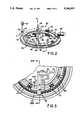
- FIG. 3is a fragmentary plan view of the incubator of FIG. 2 with the cover removed;
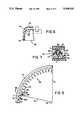
- FIG. 4is a fragmentary isometric view similar to that of FIG. 2, showing details of a segment of the incubator;
- FIG. 5is a fragmentary plan view of the outer ring of the incubator, showing one quadrant which repeats itself around the circumference of the ring;
- FIG. 6is a section view taken generally along the line VI--VI of FIG. 5, the associated stationary track and a cuvette being shown in phantom;
- FIG. 7is a fragmentary sectional view taken generally along the line VII--VII of FIG. 5, and showing a cuvette in solid lines;
- FIG. 8is a fragmentary plan view of one quadrant of the inner ring, which quadrant repeats itself around the circumference of the ring;
- FIG. 9is a section view taken along the line IX--IX of FIG. 8, the associated track and cuvette being shown in phantom;
- FIG. 10is a plan view of a preferred form of the stationary track associated with the incubator.
- FIG. 11is a section view taken generally along the line XI--XI of FIG. 10;
- FIG. 12is a section view taken generally along the line XII XII of FIG. 10;
- FIG. 13is a plan view of just the transfer means 00 for moving a cuvette off the incubator rings;
- FIG. 14is a partially schematic, fragmentary section view taken generally along the line XIV--XIV of FIG. 3;
- FIGS. 15-16are fragmentary elevational views in section similar to FIG. 14, showing the shuttle mechanism as it moves the cuvettes from one ring to another and then out of the incubator;
- FIG. 17is a section view taken generally along the lines XVII--XVII of FIG. 1,
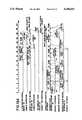
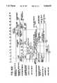
- FIG. 18A-Bare timing diagrams showing representative timing of the operations provided by the incubator of the invention.
- FIG. 19is a schematic plan view of an alternate form of the incubator, wherein the rings are not concentric.
- FIG. 20is a fragmentary section view taken generally along the ling XX--XX of FIG. 19.
- the inventionis hereinafter described in connection with the preferred embodiments of an incubator of an analyzer having plural processing stations disposed around concentrically mounted plural rings, of a preferred type that make use of a reaction cuvette and certain reagents, to treat a sample obtained from a sample supply station by aspiration.
- the inventionis useful regardless of the number and type of processing stations of the analyzer, regardless of the type of cuvettes and reagents used, whether the rings are concentrically mounted or not, and regardless of how cuvettes, reagents and samples are supplied to the incubator, since those features are not the invention, as long as at least one reagent addition station is permanently disposed adjacent to at least each of the plural rings of the incubator to enhance throughput.
- "reagent addition station”means, the location at the respective ring at which the function of reagent addition occurs. The apparatus used at such a station may, and in fact preferably does, move to other locations as well.
- the incubator of the inventionis constructed for use in an analyzer 10 comprising a sample supply station 12, a cuvette supply station 14, FIG. 2, a reagent supply station 16, FIG. 1, incubator 50, means 20 and 22 for transferring sample and reagent to a cuvette disposed in an outer ring of incubator 50, signal reagent supply station 24, means 26 for transferring signal reagent to the cuvette in an inner ring of incubator 50, cuvette wash station 30, and luminometer 32.
- any suitable constructionincluding conventional devices, can be used for the sample supply station 12, cuvette supply station 14, reagent supply station 16, transfer means 20, 22 and 26, signal reagent supply station 24, wash dispenser 30, and luminometer 32.
- supply station 12includes a position having a device 13 therein that is aligned for sample transfer.
- Unseful devices 13include those described and claimed in commonly owned, pending U.S. application Ser. No. 859,780 filed on Mar. 30, 1992 by Tomasso et al, entitled “Tray and Magnetic Conveyor”.
- Supply station 16includes a rotor 34, transfer means 20, 22 and 26 are all preferably pivoting aspirators, the aspirator at transfer means 26 having dual probes 36.
- Transfer means 20preferably uses disposable tips, which can be presented for pick-up on supply station 12. Additional tips 37 can be presented on turntable 38 for use by means 20 during a dilution step.
- the aspirator for transfer means 22preferably uses a more permanent dispensing tip, which uses a wash station 40 as is conventional.
- Cuvettescan be disposed for dispensing at station 14 by mounting them in, e.g., a ring 42 that moves with rotor 16, any suitable pusher 43, FIG. 2, being used to displace a cuvette from ring 42 into incubator 50 below.
- any cuvettecan be used, preferably it is a cup-like container "C", having on its inside wall surface 44 an antibody pre-attached to the wall surface.
- the antibodyis useful in a conventional sandwich assay which produces a complex of antibody-antigen-labeled antibody for generating a chemiluminescent signal.
- incubator 50comprises two concentrically mounted support rings 52, 54 for receiving and carrying cuvettes C (delivered preferably first to ring 52 by any pusher means 43), rotating means for independently rotating rings 52 and 54 about a common axis 55, moving means 200 (FIG. 3) discussed hereinafter, for moving a cuvette, arrow 56 of FIG. 2, from ring 52 to 54, processing stations around the rings, and heating means to incubate the contents of the cuvettes on rings 52 and 54.
- Rings 52 and 54are shown only schematically in FIG. 2 in association with the related components.
- Rotating means for the ringspreferably comprise gear teeth 62, 64 disposed on each of rings 52 and 54, respectively, to be driven by pinion gears 66 and 68.
- FIGS. 1 and 2Station 72 is permanently disposed above ring 52 and is the place where the dispensing tip 37 of aspirator 20 (not shown in FIG. 2) descends to dispense sample into a cuvette in ring 52.
- First reagent addition station 74is permanently disposed at least above ring 52 so that the permanent tip of aspirator 22 can dispense at least a first reagent into a cuvette in ring 52.
- aspirator 22can also be used to dispense a second reagent, namely a conjugate reagent, as well.
- Second reagent addition station 76here for signal reagent, is disposed permanently above at least inner ring 54, to descend to dispense signal reagent into a cuvette in ring 54.
- Wash dispensing station 78is disposed permanently above ring 54 for washing cuvettes using wash dispenser 30.
- Luminometer 32is permanently disposed above ring 54 for reading chemiluminescence.
- transfer means 200(FIGS. 3 and 14-16) is disposed at station 80 to transfer cuvettes from ring 52 to ring 54, FIG. 2, arrow 56, and then from ring 54 to a dump, arrow 82, or back to ring 52 temporarily.
- reagent addition stations 74 and 76can be constructed to bridge both rings, if desired, so as to allow the respective transfer means to supply reagent to both rings, albeit in separate sequences.
- the temperature control for rings 52 and 54comprise any conventional heating mechanism, such as heater elements (not shown) disposed in a cover plate 90, shown in phantom, and in stationary support tracks, e.g., track 100 disposed below both the rings, described hereinafter.
- Cover plate 90is apertured at the processing stations, such as entrance port 70, an access port 102 for station 74, and the others not shown in the rest of the cover plate needed for stations 76, 78 and luminometer 32. Additionally, cover plate 90 is removed at groove 104 at station to accommodate transfer means 200, shown hereinafter.
- Outer ring 52preferably comprises an annulus defined principally by a continuous outer shoulder 110, FIGS. 4-6, having an outside radius R 1 extending from axis 55, FIG. 5.
- slots 112 for each cuvettenotches are formed in the annulus from the inside surface 114 of the annulus having an inside radius of curvature R 2 .
- the notchesare open towards axis 55, so that a cuvette C (in phantom) can be moved from outer ring 52 to the inner ring and back if necessary, without taking the cuvette out of the plane of the rings, the rings being co-planar as shown.
- spokes 116can have a variety of cross-sectional shapes, preferred is one which is an upside-down T such that the top portion "t" of cuvette C is held between fixed shoulders 118 to prevent pivoting about point 120, arrow 122 (The support of the cuvettes is most clearly shown in FIG. 7). Shoulders 118 are particularly useful if track 100 is provided with optional ribs 160, as shown, as shoulders 118 then reduce the rocking motion 122 that would otherwise be induced.
- gear teeth 62preferably depend from the bottom portion of ring 52.
- Inner ring 54comprises, FIGS. 4 and 8-9, a base annulus 130 extending completely around the circumference and having an inside radius of curvature R 3 measured from axis 55, FIG. 8.
- a skirt with gear teeth 64mounted preferably on the inside portion of annulus 130 is a skirt with gear teeth 64, FIG. 9.
- notches 142are in pairs with a narrow flange 136 dividing up each pair.
- the pitch P 1 between each of every other pairis controlled to match the angular spacing around the circumference of stations 76, 78 and 32.
- Pitch P 2 for the intermediate set of pairsequals pitch P 1 , but the spacing d 1 and d 2 that positions each pair from its adjacent pair need not be equal.
- Each flange 134 and 136is shaped in cross-section as an upside down “T”, similar to the spokes 116 of ring 52, FIG. 7, to provide a shoulder 144 to support upper portion "t” to the cuvette (in phantom).
- notches 142differ from notches 112 of ring 52 in that they are open in both directions, away and towards axis 55, FIGS. 4 and 9. This is needed to allow a cuvette to be moved into ring 54 from ring 52, and then into the dump, arrow 82 of FIG. 1, that is inside annulus 130.
- Each of rings 52 and 54includes flag means (not shown) that allow either a "home" position, or each cuvette position, to be sensed by a conventional sensor.
- FIGS. 11 and 12can have a variety of surface configurations. If cuvettes C are agitated while on rings 52 and 54 by some other mechanism, then the top surface of tracks 100 can be smooth, except for rails 150, 152 and 154, described hereinafter. The top surface of each track is provided with ribs 160, to cause cuvettes C to be agitated. More specifically, FIGS. 10 and 17, tracks 100 and 100' are provided with an outside guide rail 150 that runs along outside of the path of cuvettes C carried by ring 52, FIG. 17.
- Track 100'is provided with an inside guide rail 152 that runs along inside of the path of cuvettes C' carried by ring 54, and a guide rail 154 is disposed between the aforesaid two tracks and hence between rings 52 and 54.
- Rails 150, 152 and 154serve to retain the cuvettes from being inadvertently displaced sideways, towards or away from axis 55.
- FIG. 10only guide rail 150 extends completely around the circumference of track 100.
- Guide rail 152is continuous except for notch 156 at station 80, so that cuvettes C', FIG. 16, can be dumped from ring 54.
- Guide rail 154is the same as rail 152--it is continuous except for a notch 158 at station 80, to allow transfer of cuvettes from ring 52 to ring 54.
- tracks 100 and 100' between paired rails 150, 152, and 154can be smooth, but are preferably provided with ribs 160, as are more clearly shown in FIGS. 11 and 12.
- the pitch "p" and height “h”are adjusted to give agitation to the contents of cuvettes C and C' to cause mixing but without spilling liquid from the cuvettes.
- the values of p and hdepend on the rate of mixing that is desired, as well as the speed of transit over the ribs and the height of the cuvette. Further, pitch p can be different for each track, if the transit speed is different.
- hcan vary between about 0.6 mm and about 3.0 mm
- pcan vary between about 1 mm and about 5.0 mm, with angle alpha, FIG. 12, being between about 40 degrees and about 50 degrees. Because of restraining shoulders 118 and 144, the cuvettes are induced to "bump" over the ribs, within the confines of cover plate 90, FIG. 17. That is, cover 90, FIGS. 7 and 17, assists in preventing the cuvettes from rising too far out of their notches.
- transfer means 200Means are needed for moving cuvettes from ring 52 to ring 54, and then off ring 54 out to dump.
- transfer means 200FIGS. 13-16.
- Such meanscomprise preferably a push rod 202, 204 for each of the outer and inner rings 52 and 54, respectively, mounted for transverse, reciprocal movement above their respective rings.
- Each rodhas a terminal lip 206, FIGS. 14-16, which depends down far enough to engage any cuvette that is aligned therewith when the rod is pulled towards axis 55.
- a drivecan be provided for each.
- only rod 204is driven (along tracks 205, FIG.
- Rod 202is a follower rod that is slidably and freely mounted on track 212, with tabs 214 and 216 rising therefrom, FIGS. 14-16, to be engaged by a collar 218 on rod 204 that encircles rod 202.
- transfer means 200will be readily apparent from the preceding. As shown in FIGS. 14-16, when a cuvette shown in phantom needs to be transferred at station 80 from ring 52 to ring 54, push rod 204 is drawn back, arrow 220, by lead screw 208, until collar 218 engages tab 214. This causes rod 202 to also traverse towards axis 55, from its phantom position, causing lip 206 thereof to move cuvette C to its solid position on ring 54. The next part of the cycle of movement, FIG.
- the last part of the cycle of movementis that used to transfer a cuvette C' from ring 54 to dump, FIG. 16, at station 80.
- Lead screw 208simply withdraws enough to cause lip 206 of rod 204 to pull cuvette C' off ring 54.
- one of the notches 142is maintained empty of cuvettes to provide clearance for movement of lip 206 between rings.
- the cuvetteis transferred back to outer ring 52 for further reagent addition and incubation, before returning to ring 54 for washing and reading.
- FIG. 17In addition to heated cover 90 and stationary tracks 100, 100', additional insulative enclosures are preferably provided, FIG. 17, to retain the heat for incubation of incubator 50. That is, a housing 300 is mounted on a base 302 of an insulative material, with suitable apertures 304 positioned for access to the incubator. Those apertures are generally aligned with the apertures of cover 90, FIG. 2. Most preferably, apertures 304 are removably covered by doors 310, which can be operated by any suitable means, such as a cam 312 driven by motor 314 to engage cam followers 316 on the doors, as is more fully described and claimed in commonly owned U.S. application Ser. No. 887,976 filed on May 22, 1992 by J. J. Porte and entitled CAM-OPERATED DOORS FOR AN INCUBATOR. Most preferably, drive shaft 320 of motor 314 is on axis 55, FIG. 17.
- the actual control of the temperature within incubator 50is variable, depending on the reactions desired.
- the temperature of outer ring 52is preferably kept within 0.5° C. of the desired temperature, e.g., of 37°, as most of the incubation occurs while on this ring.
- Inner ring 54can be within 2° C. of the desired target temperature, but most preferably ⁇ 0.5° C.
- the timing sequence for the operation of the incubatorwill of course depend upon a large variety of factors, including a) the angular position of each processing station about the rings of the incubator, and b) the chemistry of the immunoassays in question, as will be readily apparent.
- FIG. 18A and BA representative timing diagram is given in FIG. 18A and B.
- reagent transfer means 22goes to reagent supply station 16, FIG. 1, twice for two different reagents.
- the first 15 functionsare defined as operations pertaining to outer ring 52, whereas the remainder are for inner ring 54.
- Step 1a cuvette C is dropped into a notch in outer ring 52.
- Step 2ring 52 is rotated to move that cuvette into position at station 72 (FIG. 2) to receive a sample liquid.
- Step 3sample is dispensed at station 72.
- Step 4ring 52 is rotated to move the cuvette to reagent addition station 74 (FIG. 2).
- Step 5reagent is dispensed at station 74 using transfer means 22.
- Step 5'rotate ring 52 to allow other operations on other cuvettes, while incubating and agitating this cuvette.
- Step 6rotate ring 52 to move it back to station 74 for optional conjugate reagent addition.
- Step 7dispense second reagent, if needed.
- Step 8incubate and agitate for a minimum of 15 minutes.
- Step 9rotate ring 52 (and ring 54) to place cuvette at station 80.
- Step 10activate transfer means 200 to move cuvette from ring 52 to ring 54.
- Step 11align cuvette on ring 54 at station 78 for washing of the cuvette.
- Step 12wash cuvette at station 78.
- Step 13repeat alignment step 11 until cuvette is at station 76.
- Step 14dispense signal reagent at station 76.
- Step 15repeat alignment step 11 until cuvette is at read station 32.
- Step 16read cuvette with the luminometer.
- Step 17repeat step 11 until cuvette is at station 80.
- Step 18activate push rod 204 to dump the cuvette.
- rings 52A and 54Acan be side-by-side, separately rotated about separate axes by gears 66A and 68A, FIG. 19.
- the various stations 14A, 72A, 74Aare disposed adjacent ring 52A as before, whereas stations 32A, 76A and 78A are disposed adjacent ring 54A as before.
Landscapes
- Chemical & Material Sciences (AREA)
- Chemical Kinetics & Catalysis (AREA)
- Physics & Mathematics (AREA)
- Health & Medical Sciences (AREA)
- Life Sciences & Earth Sciences (AREA)
- Analytical Chemistry (AREA)
- Biochemistry (AREA)
- General Health & Medical Sciences (AREA)
- General Physics & Mathematics (AREA)
- Immunology (AREA)
- Pathology (AREA)
- Automatic Analysis And Handling Materials Therefor (AREA)
- Sampling And Sample Adjustment (AREA)
Abstract
Description
Claims (13)
Priority Applications (11)
| Application Number | Priority Date | Filing Date | Title |
|---|---|---|---|
| US07/887,990US5244633A (en) | 1992-05-22 | 1992-05-22 | Analyzer incubator with plural independently driven rings supporting cuvettes |
| TW082103276ATW227044B (en) | 1992-05-22 | 1993-04-28 | |
| CA002095496ACA2095496A1 (en) | 1992-05-22 | 1993-05-04 | Analyzer incubator with plural, independently driven rings supporting cuvettes |
| EP93201394AEP0571032A1 (en) | 1992-05-22 | 1993-05-15 | Analyzer incubators |
| EP93201396AEP0571034A1 (en) | 1992-05-22 | 1993-05-15 | Mixing mechanism for analyzers |
| FI932328AFI932328L (en) | 1992-05-22 | 1993-05-21 | ANALYSATORODLINGSNORDNING MED FLERA SEPARAT DRIVNA RINGAR SOM BAER UPPKYVETTER |
| JP11943293AJP3256328B2 (en) | 1992-05-22 | 1993-05-21 | Incubator and incubation method |
| FI932329AFI932329L (en) | 1992-05-22 | 1993-05-21 | RIBBAD MEKANISM FOER BLANDNING AV ETT PROV GENOM VIBRATION |
| JP5119437AJPH0634641A (en) | 1992-05-22 | 1993-05-21 | Analyzer |
| KR1019930008916AKR100226294B1 (en) | 1992-05-22 | 1993-05-22 | Analyzer incubator with multiple cuvette support rings driven independently |
| KR1019930008917AKR930023727A (en) | 1992-05-22 | 1993-05-22 | Ribbed mixing device for mixing samples by vibratory motion |
Applications Claiming Priority (1)
| Application Number | Priority Date | Filing Date | Title |
|---|---|---|---|
| US07/887,990US5244633A (en) | 1992-05-22 | 1992-05-22 | Analyzer incubator with plural independently driven rings supporting cuvettes |
Publications (1)
| Publication Number | Publication Date |
|---|---|
| US5244633Atrue US5244633A (en) | 1993-09-14 |
Family
ID=25392290
Family Applications (1)
| Application Number | Title | Priority Date | Filing Date |
|---|---|---|---|
| US07/887,990Expired - LifetimeUS5244633A (en) | 1992-05-22 | 1992-05-22 | Analyzer incubator with plural independently driven rings supporting cuvettes |
Country Status (6)
| Country | Link |
|---|---|
| US (1) | US5244633A (en) |
| EP (1) | EP0571032A1 (en) |
| JP (1) | JP3256328B2 (en) |
| CA (1) | CA2095496A1 (en) |
| FI (1) | FI932328L (en) |
| TW (1) | TW227044B (en) |
Cited By (43)
| Publication number | Priority date | Publication date | Assignee | Title |
|---|---|---|---|---|
| US5360597A (en)* | 1993-03-22 | 1994-11-01 | Eastman Kodak Company | Ribbed mechanism for mixing sample by vibration |
| US5380487A (en)* | 1992-05-05 | 1995-01-10 | Pasteur Sanofi Diagnostics | Device for automatic chemical analysis |
| US5441891A (en)* | 1994-05-26 | 1995-08-15 | Burkovich; Robert A. | Transfer mechanism within an incubator |
| US5456883A (en)* | 1994-06-27 | 1995-10-10 | Johnson & Johnson Clinical Diagnostics, Inc. | Mechanism for reading and removing reaction cuvettes in an incubator |
| WO1996003658A1 (en)* | 1994-07-28 | 1996-02-08 | Anagen (Uk) Limited | Incubation vessel support |
| EP0710840A1 (en) | 1994-11-07 | 1996-05-08 | JOHNSON & JOHNSON CLINICAL DIAGNOSTICS, INC. | Cuvette conveyor and sensor |
| US5599501A (en)* | 1994-11-10 | 1997-02-04 | Ciba Corning Diagnostics Corp. | Incubation chamber |
| WO1997041445A1 (en)* | 1996-04-26 | 1997-11-06 | Dade International Inc. | Method and apparatus for pre-treating samples in an automatic chemical analyzer |
| US5720377A (en)* | 1995-07-14 | 1998-02-24 | Chiron Diagnostics Corporation | Magnetic conveyor system |
| US5736403A (en)* | 1996-11-13 | 1998-04-07 | Johnson & Johnson Clinical Diagnostics, Inc. | Determining height variations around a rotor |
| US5735387A (en)* | 1995-07-14 | 1998-04-07 | Chiron Diagnostics Corporation | Specimen rack handling system |
| US5753512A (en)* | 1996-11-13 | 1998-05-19 | Johnson & Johnson Clinical Diagnostics, Inc | Determining liquid volumes in cup-like vessels on a rotor having vertical deviations |
| EP0831329A3 (en)* | 1996-09-19 | 1998-08-12 | Abbott Laboratories | Automatic analyser |
| US5795784A (en) | 1996-09-19 | 1998-08-18 | Abbott Laboratories | Method of performing a process for determining an item of interest in a sample |
| US5856194A (en) | 1996-09-19 | 1999-01-05 | Abbott Laboratories | Method for determination of item of interest in a sample |
| US5891734A (en)* | 1994-08-01 | 1999-04-06 | Abbott Laboratories | Method for performing automated analysis |
| US6436349B1 (en) | 1991-03-04 | 2002-08-20 | Bayer Corporation | Fluid handling apparatus for an automated analyzer |
| US20020131895A1 (en)* | 2001-03-16 | 2002-09-19 | Gjerdingen Donald J. | Rotary incubation station for immunoassay systems |
| US6498037B1 (en) | 1991-03-04 | 2002-12-24 | Bayer Corporation | Method of handling reagents in a random access protocol |
| US20030017613A1 (en)* | 2001-07-13 | 2003-01-23 | Jakubowicz Raymond Francis | Tandem incubator for clinical analyzer |
| US6551833B1 (en)* | 1999-03-12 | 2003-04-22 | Innotrac Diagnostics Oy | Method for handling samples and diagnostic measuring device |
| US6588625B2 (en) | 2001-04-24 | 2003-07-08 | Abbott Laboratories | Sample handling system |
| US20040134750A1 (en)* | 2001-04-24 | 2004-07-15 | Luoma Robert Paul | Assay testing diagnostic analyzer |
| US20040191923A1 (en)* | 2003-03-31 | 2004-09-30 | Tomasso David Angelo | Test element holder with a probe guide for an analyzer |
| EP1477810A1 (en)* | 2003-05-13 | 2004-11-17 | Ortho-Clinical Diagnostics, Inc. | Analyzer having concentric rotors |
| US20050123444A1 (en)* | 2003-12-08 | 2005-06-09 | Tomasso David A. | Analyzer having removable holders or a centrifuge |
| US20050238248A1 (en)* | 2004-04-26 | 2005-10-27 | Mitutoyo Corporation | Image processing apparatus using morphology |
| US20080102527A1 (en)* | 1998-05-01 | 2008-05-01 | Gen-Probe Incorporated | Method for Introducing A Fluid Into A Reaction Receptacle Contained Within A Temperature-Controlled Environment |
| US20090067280A1 (en)* | 1998-05-01 | 2009-03-12 | Gen-Probe Incorporated | Method for Agitating the Contents of A Reaction Receptacle Within A Temperature-Controlled Environment |
| US7597847B2 (en) | 2003-03-31 | 2009-10-06 | Ortho-Clinical Diagnostics, Inc. | Analyzer having a stationary multifunction probe |
| CN103910171A (en)* | 2013-01-09 | 2014-07-09 | 西门子医学诊断产品有限责任公司 | Device for transporting reaction vessels |
| WO2014149118A3 (en)* | 2013-03-15 | 2014-11-13 | Abbott Laboratories | Diagnostic analyzers with pretreatment carousels and related methods |
| US9057714B2 (en) | 2005-05-04 | 2015-06-16 | Abbott Laboratories | Reagent and sample handling device for automatic testing system |
| US9335338B2 (en) | 2013-03-15 | 2016-05-10 | Toshiba Medical Systems Corporation | Automated diagnostic analyzers having rear accessible track systems and related methods |
| US9400285B2 (en) | 2013-03-15 | 2016-07-26 | Abbot Laboratories | Automated diagnostic analyzers having vertically arranged carousels and related methods |
| US9513303B2 (en) | 2013-03-15 | 2016-12-06 | Abbott Laboratories | Light-blocking system for a diagnostic analyzer |
| US9588069B2 (en) | 2012-07-31 | 2017-03-07 | Gen-Probe Incorporated | Methods for performing thermal melt analysis |
| US9632103B2 (en) | 2013-03-15 | 2017-04-25 | Abbott Laboraties | Linear track diagnostic analyzer |
| US9993820B2 (en) | 2013-03-15 | 2018-06-12 | Abbott Laboratories | Automated reagent manager of a diagnostic analyzer system |
| US10031085B2 (en) | 2014-07-24 | 2018-07-24 | Ortho-Clinical Diagnostics, Inc. | Point of care analytical processing system |
| US10473650B2 (en) | 2017-03-01 | 2019-11-12 | Leadway (Hk) Limited | Reagent mixing and conveying device and reagent mixing method |
| US20200110103A1 (en)* | 2018-10-08 | 2020-04-09 | Team Conveyer Intellectual Properties, LLC | Coordinated conveyers in an automated system |
| EP4332581A4 (en)* | 2021-04-30 | 2025-04-30 | Shenzhen Yhlo Biotech Co., Ltd | REACTION CUP TRANSPORT DEVICE AND IMMUNOLOGICAL DETECTION APPARATUS |
Families Citing this family (8)
| Publication number | Priority date | Publication date | Assignee | Title |
|---|---|---|---|---|
| WO1996038479A1 (en)* | 1995-05-30 | 1996-12-05 | Fujisawa Pharmaceutical Co., Ltd. | Method of diagnosis of insulin dependent diabetes melitus and kit to be used therein |
| EP0843162B1 (en)* | 1996-11-13 | 2007-03-21 | Ortho-Clinical Diagnostics, Inc. | Determining liquid volumes in cup-like vessels being positioned on a rotor having a run-out in vertical direction |
| FR2804510B1 (en)* | 2000-01-28 | 2003-02-07 | Biomerieux Sa | WC BASES, AUTOMATED BIOLOGICAL ANALYSIS APPARATUS USING SUCH WC WORKS, MEANS FOR TRANSFERRING WC WORKS IN SUCH APPARATUS, AND TRANSFER METHOD |
| US6627156B1 (en) | 2000-06-22 | 2003-09-30 | Beckman Coulter, Inc. | Cap piercing station for closed container sampling system |
| US7402282B2 (en)* | 2001-07-20 | 2008-07-22 | Ortho-Clinical Diagnostics, Inc. | Auxiliary sample supply for a clinical analyzer |
| EP1477813B1 (en)* | 2003-05-13 | 2008-01-02 | The Automation Partnership (Cambridge) Limited | Vial transfer apparatus |
| EP2128627B1 (en)* | 2008-05-30 | 2013-01-09 | F. Hoffmann-La Roche AG | Analyzer for performing medical diagnostic analysis |
| CN109975277B (en)* | 2017-12-28 | 2024-08-13 | 深圳市新产业生物医学工程股份有限公司 | Chemiluminescent detector and detection method thereof |
Citations (9)
| Publication number | Priority date | Publication date | Assignee | Title |
|---|---|---|---|---|
| US3728227A (en)* | 1968-06-18 | 1973-04-17 | North American Rockwell | Microorganism culture apparatus |
| US3756920A (en)* | 1971-04-30 | 1973-09-04 | Nasa | In biological samples my measuring light reactions automatic instrument for chemical processing to dedect microorganisms |
| US3758274A (en)* | 1971-07-30 | 1973-09-11 | Sherwood Medical Ind Inc | Reagent reservoir and magnetic stirring system |
| US4219527A (en)* | 1978-10-31 | 1980-08-26 | Celanese Corporation | Extrusion grade polyethylene terephthalate |
| US4595562A (en)* | 1981-07-20 | 1986-06-17 | American Hospital Supply Corporation | Loading and transfer assembly for chemical analyzer |
| US4699766A (en)* | 1985-05-30 | 1987-10-13 | Kabushiki Kaisha Toshiba | Automatic chemical analyzer |
| US4834944A (en)* | 1982-11-09 | 1989-05-30 | Mitsubishi Chemical Industries Limited | Automatic analytical apparatus |
| DE3839080A1 (en)* | 1987-11-20 | 1989-06-01 | Hitachi Ltd | AUTOMATIC ANALYSIS SYSTEM AND ANALYSIS METHOD USING THE SYSTEM |
| US4906433A (en)* | 1986-06-24 | 1990-03-06 | Kabushiki Kaisha Toshiba | Automatic chemical analyzer |
Family Cites Families (4)
| Publication number | Priority date | Publication date | Assignee | Title |
|---|---|---|---|---|
| US3504376A (en)* | 1966-12-15 | 1970-03-31 | Xerox Corp | Automated chemical analyzer |
| DE2020711C3 (en)* | 1970-04-28 | 1974-06-20 | Siemens Ag, 1000 Berlin Und 8000 Muenchen | Sample distributor for liquid test material |
| FR2280894A1 (en)* | 1974-07-30 | 1976-02-27 | Paquelet Jean | Automatic chemical and biological analysis - with automatic sample transfer and reactant add and reaction kinetics study capability |
| DE3029795C2 (en)* | 1979-08-07 | 1983-10-27 | Olympus Optical Co., Ltd., Tokyo | Automatic analyzer for liquid samples |
- 1992
- 1992-05-22USUS07/887,990patent/US5244633A/ennot_activeExpired - Lifetime
- 1993
- 1993-04-28TWTW082103276Apatent/TW227044B/zhactive
- 1993-05-04CACA002095496Apatent/CA2095496A1/ennot_activeAbandoned
- 1993-05-15EPEP93201394Apatent/EP0571032A1/ennot_activeCeased
- 1993-05-21FIFI932328Apatent/FI932328L/enunknown
- 1993-05-21JPJP11943293Apatent/JP3256328B2/ennot_activeExpired - Lifetime
Patent Citations (10)
| Publication number | Priority date | Publication date | Assignee | Title |
|---|---|---|---|---|
| US3728227A (en)* | 1968-06-18 | 1973-04-17 | North American Rockwell | Microorganism culture apparatus |
| US3756920A (en)* | 1971-04-30 | 1973-09-04 | Nasa | In biological samples my measuring light reactions automatic instrument for chemical processing to dedect microorganisms |
| US3758274A (en)* | 1971-07-30 | 1973-09-11 | Sherwood Medical Ind Inc | Reagent reservoir and magnetic stirring system |
| US4219527A (en)* | 1978-10-31 | 1980-08-26 | Celanese Corporation | Extrusion grade polyethylene terephthalate |
| US4595562A (en)* | 1981-07-20 | 1986-06-17 | American Hospital Supply Corporation | Loading and transfer assembly for chemical analyzer |
| US4834944A (en)* | 1982-11-09 | 1989-05-30 | Mitsubishi Chemical Industries Limited | Automatic analytical apparatus |
| US4699766A (en)* | 1985-05-30 | 1987-10-13 | Kabushiki Kaisha Toshiba | Automatic chemical analyzer |
| US4906433A (en)* | 1986-06-24 | 1990-03-06 | Kabushiki Kaisha Toshiba | Automatic chemical analyzer |
| DE3839080A1 (en)* | 1987-11-20 | 1989-06-01 | Hitachi Ltd | AUTOMATIC ANALYSIS SYSTEM AND ANALYSIS METHOD USING THE SYSTEM |
| US5051238A (en)* | 1987-11-20 | 1991-09-24 | Hitachi, Ltd. | Automatic analyzing system |
Cited By (92)
| Publication number | Priority date | Publication date | Assignee | Title |
|---|---|---|---|---|
| US6498037B1 (en) | 1991-03-04 | 2002-12-24 | Bayer Corporation | Method of handling reagents in a random access protocol |
| US6436349B1 (en) | 1991-03-04 | 2002-08-20 | Bayer Corporation | Fluid handling apparatus for an automated analyzer |
| US7182912B2 (en) | 1991-03-04 | 2007-02-27 | Bayer Corporation | Fluid handling apparatus for an automated analyzer |
| US5658799A (en)* | 1992-05-05 | 1997-08-19 | Pasteur Sanofi Diagnostics | Method and device for automatic chemical analysis |
| US5380487A (en)* | 1992-05-05 | 1995-01-10 | Pasteur Sanofi Diagnostics | Device for automatic chemical analysis |
| US5846491A (en)* | 1992-05-05 | 1998-12-08 | Pasteur Sanofi Diagnostics, S.A. | Device for automatic chemical analysis |
| US5575976A (en)* | 1992-05-05 | 1996-11-19 | Pasteur Sanofi Diagnostics, S.A. | Device for automatic chemical analysis |
| US5693292A (en)* | 1992-05-05 | 1997-12-02 | Pasteur Sanofi Diagnostics | Device for automatic chemical analysis |
| US5360597A (en)* | 1993-03-22 | 1994-11-01 | Eastman Kodak Company | Ribbed mechanism for mixing sample by vibration |
| US5441891A (en)* | 1994-05-26 | 1995-08-15 | Burkovich; Robert A. | Transfer mechanism within an incubator |
| EP0684478A2 (en) | 1994-05-26 | 1995-11-29 | Johnson & Johnson Clinical Diagnostics, Inc. | Transfer mechanism within an incubator |
| EP0684478A3 (en)* | 1994-05-26 | 1996-08-28 | Johnson & Johnson Clin Diag | Transfer mechanism within an incubator. |
| EP0690309A3 (en)* | 1994-06-27 | 1997-01-15 | Johnson & Johnson Clin Diag | Mechanism for reading and removing reaction cuvettes in an incubator |
| US5456883A (en)* | 1994-06-27 | 1995-10-10 | Johnson & Johnson Clinical Diagnostics, Inc. | Mechanism for reading and removing reaction cuvettes in an incubator |
| WO1996003658A1 (en)* | 1994-07-28 | 1996-02-08 | Anagen (Uk) Limited | Incubation vessel support |
| US6015532A (en)* | 1994-07-28 | 2000-01-18 | Alfa Biotech S.P.A. | Incubation vessel support |
| US5891734A (en)* | 1994-08-01 | 1999-04-06 | Abbott Laboratories | Method for performing automated analysis |
| EP0710840A1 (en) | 1994-11-07 | 1996-05-08 | JOHNSON & JOHNSON CLINICAL DIAGNOSTICS, INC. | Cuvette conveyor and sensor |
| US5567387A (en)* | 1994-11-07 | 1996-10-22 | Johnson & Johnson Clinical Diagnostics, Inc. | Cuvette conveyor and sensor |
| US5599501A (en)* | 1994-11-10 | 1997-02-04 | Ciba Corning Diagnostics Corp. | Incubation chamber |
| US5827478A (en)* | 1994-11-10 | 1998-10-27 | Chiron Diagnostics Corporation | Incubation chamber |
| US5720377A (en)* | 1995-07-14 | 1998-02-24 | Chiron Diagnostics Corporation | Magnetic conveyor system |
| US5735387A (en)* | 1995-07-14 | 1998-04-07 | Chiron Diagnostics Corporation | Specimen rack handling system |
| US5985672A (en)* | 1996-04-26 | 1999-11-16 | Dade Behring Inc. | Method and apparatus for pre-treating samples in an automatic chemical analyzer |
| WO1997041445A1 (en)* | 1996-04-26 | 1997-11-06 | Dade International Inc. | Method and apparatus for pre-treating samples in an automatic chemical analyzer |
| EP1167977A1 (en)* | 1996-09-19 | 2002-01-02 | Abbott Laboratories | Method and structure for determination of item of interest in a sample |
| US6562298B1 (en) | 1996-09-19 | 2003-05-13 | Abbott Laboratories | Structure for determination of item of interest in a sample |
| US5795784A (en) | 1996-09-19 | 1998-08-18 | Abbott Laboratories | Method of performing a process for determining an item of interest in a sample |
| EP0831329A3 (en)* | 1996-09-19 | 1998-08-12 | Abbott Laboratories | Automatic analyser |
| US5856194A (en) | 1996-09-19 | 1999-01-05 | Abbott Laboratories | Method for determination of item of interest in a sample |
| US5736403A (en)* | 1996-11-13 | 1998-04-07 | Johnson & Johnson Clinical Diagnostics, Inc. | Determining height variations around a rotor |
| US5753512A (en)* | 1996-11-13 | 1998-05-19 | Johnson & Johnson Clinical Diagnostics, Inc | Determining liquid volumes in cup-like vessels on a rotor having vertical deviations |
| US8337753B2 (en) | 1998-05-01 | 2012-12-25 | Gen-Probe Incorporated | Temperature-controlled incubator having a receptacle mixing mechanism |
| US8709814B2 (en) | 1998-05-01 | 2014-04-29 | Gen-Probe Incorporated | Method for incubating the contents of a receptacle |
| US8318500B2 (en)* | 1998-05-01 | 2012-11-27 | Gen-Probe, Incorporated | Method for agitating the contents of a reaction receptacle within a temperature-controlled environment |
| US8309358B2 (en)* | 1998-05-01 | 2012-11-13 | Gen-Probe Incorporated | Method for introducing a fluid into a reaction receptacle contained within a temperature-controlled environment |
| US8221682B2 (en) | 1998-05-01 | 2012-07-17 | Gen-Probe Incorporated | System for incubating the contents of a reaction receptacle |
| US8192992B2 (en) | 1998-05-01 | 2012-06-05 | Gen-Probe Incorporated | System and method for incubating the contents of a reaction receptacle |
| US20090067280A1 (en)* | 1998-05-01 | 2009-03-12 | Gen-Probe Incorporated | Method for Agitating the Contents of A Reaction Receptacle Within A Temperature-Controlled Environment |
| US20080102527A1 (en)* | 1998-05-01 | 2008-05-01 | Gen-Probe Incorporated | Method for Introducing A Fluid Into A Reaction Receptacle Contained Within A Temperature-Controlled Environment |
| US6551833B1 (en)* | 1999-03-12 | 2003-04-22 | Innotrac Diagnostics Oy | Method for handling samples and diagnostic measuring device |
| US20020131895A1 (en)* | 2001-03-16 | 2002-09-19 | Gjerdingen Donald J. | Rotary incubation station for immunoassay systems |
| US7217391B2 (en)* | 2001-03-16 | 2007-05-15 | Beckman Coulter, Inc. | Rotary incubation station for immunoassay systems |
| US20080190735A1 (en)* | 2001-04-24 | 2008-08-14 | Abbott Laboratories | Assay testing diagnostic analyzer |
| US9656266B2 (en) | 2001-04-24 | 2017-05-23 | Abbott Laboratories | Assay testing diagnostic analyzer |
| US20070010019A1 (en)* | 2001-04-24 | 2007-01-11 | Luoma Robert P Ii | Assay testing diagnostic analyzer |
| US8535624B2 (en) | 2001-04-24 | 2013-09-17 | Abbott Laboratories | Assay testing diagnostic analyzer |
| US6588625B2 (en) | 2001-04-24 | 2003-07-08 | Abbott Laboratories | Sample handling system |
| US7458483B2 (en) | 2001-04-24 | 2008-12-02 | Abbott Laboratories, Inc. | Assay testing diagnostic analyzer |
| US20040134750A1 (en)* | 2001-04-24 | 2004-07-15 | Luoma Robert Paul | Assay testing diagnostic analyzer |
| EP1402272B1 (en)* | 2001-07-13 | 2010-03-24 | Ortho-Clinical Diagnostics, Inc. | Multiple track incubator for clinical analyzer |
| US7312084B2 (en)* | 2001-07-13 | 2007-12-25 | Ortho-Clinical Diagnostics, Inc. | Tandem incubator for clinical analyzer |
| US20030017613A1 (en)* | 2001-07-13 | 2003-01-23 | Jakubowicz Raymond Francis | Tandem incubator for clinical analyzer |
| US7597847B2 (en) | 2003-03-31 | 2009-10-06 | Ortho-Clinical Diagnostics, Inc. | Analyzer having a stationary multifunction probe |
| US20040191923A1 (en)* | 2003-03-31 | 2004-09-30 | Tomasso David Angelo | Test element holder with a probe guide for an analyzer |
| US20040230400A1 (en)* | 2003-05-13 | 2004-11-18 | Tomasso David Angelo | Analyzer having concentric rotors |
| EP1477810A1 (en)* | 2003-05-13 | 2004-11-17 | Ortho-Clinical Diagnostics, Inc. | Analyzer having concentric rotors |
| US8043562B2 (en) | 2003-12-08 | 2011-10-25 | Ortho-Clinical Diagnostics, Inc. | Analyzer having removable holders or a centrifuge |
| US20050123444A1 (en)* | 2003-12-08 | 2005-06-09 | Tomasso David A. | Analyzer having removable holders or a centrifuge |
| EP1542020A2 (en) | 2003-12-08 | 2005-06-15 | Ortho-Clinical Diagnostics, Inc. | Analyzer having removable holders or a centrifuge |
| US20050238248A1 (en)* | 2004-04-26 | 2005-10-27 | Mitutoyo Corporation | Image processing apparatus using morphology |
| US9057714B2 (en) | 2005-05-04 | 2015-06-16 | Abbott Laboratories | Reagent and sample handling device for automatic testing system |
| US10191072B2 (en) | 2005-05-04 | 2019-01-29 | Abbott Laboratories | Reagent and sample handling device for automatic testing system |
| US10488353B2 (en) | 2012-07-31 | 2019-11-26 | Gen-Probe Incorporated | Apparatus and system for performing thermal melt analyses and amplifications |
| US9588069B2 (en) | 2012-07-31 | 2017-03-07 | Gen-Probe Incorporated | Methods for performing thermal melt analysis |
| CN103910171A (en)* | 2013-01-09 | 2014-07-09 | 西门子医学诊断产品有限责任公司 | Device for transporting reaction vessels |
| CN103910171B (en)* | 2013-01-09 | 2017-07-14 | 西门子医学诊断产品有限责任公司 | Device for transmitting reaction vessel |
| US9993820B2 (en) | 2013-03-15 | 2018-06-12 | Abbott Laboratories | Automated reagent manager of a diagnostic analyzer system |
| US9632103B2 (en) | 2013-03-15 | 2017-04-25 | Abbott Laboraties | Linear track diagnostic analyzer |
| US9513303B2 (en) | 2013-03-15 | 2016-12-06 | Abbott Laboratories | Light-blocking system for a diagnostic analyzer |
| US9400285B2 (en) | 2013-03-15 | 2016-07-26 | Abbot Laboratories | Automated diagnostic analyzers having vertically arranged carousels and related methods |
| US10001497B2 (en) | 2013-03-15 | 2018-06-19 | Abbott Laboratories | Diagnostic analyzers with pretreatment carousels and related methods |
| US11536739B2 (en) | 2013-03-15 | 2022-12-27 | Abbott Laboratories | Automated diagnostic analyzers having vertically arranged carousels and related methods |
| US9335338B2 (en) | 2013-03-15 | 2016-05-10 | Toshiba Medical Systems Corporation | Automated diagnostic analyzers having rear accessible track systems and related methods |
| US10197585B2 (en) | 2013-03-15 | 2019-02-05 | Abbott Laboratories | Automated diagnostic analyzers having vertically arranged carousels and related methods |
| CN109358202A (en)* | 2013-03-15 | 2019-02-19 | 雅培制药有限公司 | Automated diagnostic analyzer with vertically arranged carousel and related methods |
| US10267818B2 (en) | 2013-03-15 | 2019-04-23 | Abbott Laboratories | Automated diagnostic analyzers having rear accessible track systems and related methods |
| US10330691B2 (en) | 2013-03-15 | 2019-06-25 | Abbott Laboratories | Light-blocking system for a diagnostic analyzer |
| EP4354149A3 (en)* | 2013-03-15 | 2024-07-03 | Abbott Laboratories | Diagnostic analyzers with pretreatment carousels and related methods |
| WO2014149118A3 (en)* | 2013-03-15 | 2014-11-13 | Abbott Laboratories | Diagnostic analyzers with pretreatment carousels and related methods |
| US12228583B2 (en) | 2013-03-15 | 2025-02-18 | Abbott Laboratories | Automated diagnostic analyzers having vertically arranged carousels and related methods |
| US10775398B2 (en) | 2013-03-15 | 2020-09-15 | Abbott Laboratories | Automated diagnostic analyzers having vertically arranged carousels and related methods |
| US11125766B2 (en) | 2013-03-15 | 2021-09-21 | Abbott Laboratories | Automated diagnostic analyzers having rear accessible track systems and related methods |
| US12007403B2 (en) | 2013-03-15 | 2024-06-11 | Abbott Laboratories | Automated diagnostic analyzers having rear accessible track systems and related methods |
| US11435372B2 (en) | 2013-03-15 | 2022-09-06 | Abbott Laboratories | Diagnostic analyzers with pretreatment carousels and related methods |
| US10031085B2 (en) | 2014-07-24 | 2018-07-24 | Ortho-Clinical Diagnostics, Inc. | Point of care analytical processing system |
| US10473650B2 (en) | 2017-03-01 | 2019-11-12 | Leadway (Hk) Limited | Reagent mixing and conveying device and reagent mixing method |
| US11255846B2 (en) | 2017-03-01 | 2022-02-22 | Leadway (Hk) Limited | Reagent mixing and conveying device and reagent mixing method |
| US20200110103A1 (en)* | 2018-10-08 | 2020-04-09 | Team Conveyer Intellectual Properties, LLC | Coordinated conveyers in an automated system |
| US11754576B2 (en)* | 2018-10-08 | 2023-09-12 | Team Conveyer Intellectual Properties, LLC | Coordinated conveyers in an automated system |
| US12320819B2 (en) | 2018-10-08 | 2025-06-03 | Team Conveyer Royalty A Llc | Coordinated conveyers in an automated system |
| EP4332581A4 (en)* | 2021-04-30 | 2025-04-30 | Shenzhen Yhlo Biotech Co., Ltd | REACTION CUP TRANSPORT DEVICE AND IMMUNOLOGICAL DETECTION APPARATUS |
Also Published As
| Publication number | Publication date |
|---|---|
| JPH0634639A (en) | 1994-02-10 |
| JP3256328B2 (en) | 2002-02-12 |
| FI932328A0 (en) | 1993-05-21 |
| EP0571032A1 (en) | 1993-11-24 |
| FI932328A7 (en) | 1993-11-23 |
| FI932328L (en) | 1993-11-23 |
| CA2095496A1 (en) | 1993-11-23 |
| TW227044B (en) | 1994-07-21 |
Similar Documents
| Publication | Publication Date | Title |
|---|---|---|
| US5244633A (en) | Analyzer incubator with plural independently driven rings supporting cuvettes | |
| EP1870713B1 (en) | Apparatus for multiple automatic analysis of biosamples, method for autoanalysis, and reaction cuvette | |
| US6498037B1 (en) | Method of handling reagents in a random access protocol | |
| CA2384519C (en) | Automated analyzer | |
| EP0835452B1 (en) | Method and apparatus for pre-treating samples in an automatic chemical analyzer | |
| US4837159A (en) | Method and apparatus for effecting immunological analysis | |
| US5658799A (en) | Method and device for automatic chemical analysis | |
| US6436349B1 (en) | Fluid handling apparatus for an automated analyzer | |
| US5360597A (en) | Ribbed mechanism for mixing sample by vibration | |
| JP3559879B2 (en) | Reactor for automatic analyzer | |
| EP0563891A2 (en) | Automated immunochemical analyzer | |
| KR100226294B1 (en) | Analyzer incubator with multiple cuvette support rings driven independently | |
| JPH0577981B2 (en) | ||
| JPH0656383B2 (en) | Enzyme immunological automatic analyzer | |
| JPH0664069B2 (en) | Immunological automatic analysis method | |
| HK1114423A (en) | Biosample multiple autoanalyzer, method of autoanalysis and reaction cuvette | |
| JPH09145719A (en) | Reactor for automatic analyzer | |
| JPS62145167A (en) | Automatic analyzer |
Legal Events
| Date | Code | Title | Description |
|---|---|---|---|
| AS | Assignment | Owner name:EASTMAN KODAK COMPANY, NEW YORK Free format text:ASSIGNMENT OF ASSIGNORS INTEREST.;ASSIGNORS:JAKUBOWICZ, RAYMOND F.;PORTE, JOHANNES J.;ROBINSON, JAMES E.;REEL/FRAME:006522/0059;SIGNING DATES FROM 19920514 TO 19920518 | |
| FEPP | Fee payment procedure | Free format text:PAYOR NUMBER ASSIGNED (ORIGINAL EVENT CODE: ASPN); ENTITY STATUS OF PATENT OWNER: LARGE ENTITY | |
| AS | Assignment | Owner name:EASTMAN KODAK COMPANY, NEW YORK Free format text:ASSIGNMENT OF ASSIGNORS INTEREST;ASSIGNORS:JAKUBOWICZ, RAYMOND F.;PORTE, JOHANNES JACOBUS;ROBINSON, JAMES E.;REEL/FRAME:006566/0110;SIGNING DATES FROM 19920514 TO 19920518 | |
| STCF | Information on status: patent grant | Free format text:PATENTED CASE | |
| CC | Certificate of correction | ||
| FEPP | Fee payment procedure | Free format text:PAYER NUMBER DE-ASSIGNED (ORIGINAL EVENT CODE: RMPN); ENTITY STATUS OF PATENT OWNER: LARGE ENTITY Free format text:PAYOR NUMBER ASSIGNED (ORIGINAL EVENT CODE: ASPN); ENTITY STATUS OF PATENT OWNER: LARGE ENTITY | |
| AS | Assignment | Owner name:CLINICAL DIAGNOSTIC SYSTEMS INC., NEW YORK Free format text:ASSIGNMENT OF ASSIGNORS INTEREST;ASSIGNOR:EASTMAN KODAK COMPANY;REEL/FRAME:007453/0348 Effective date:19950118 | |
| FPAY | Fee payment | Year of fee payment:4 | |
| REFU | Refund | Free format text:REFUND - PAYMENT OF MAINTENANCE FEE, 4TH YEAR, LARGE ENTITY (ORIGINAL EVENT CODE: R183); ENTITY STATUS OF PATENT OWNER: LARGE ENTITY | |
| FPAY | Fee payment | Year of fee payment:8 | |
| FPAY | Fee payment | Year of fee payment:12 |