US5244446A - Multi-purpose torso exercise apparatus - Google Patents
Multi-purpose torso exercise apparatusDownload PDFInfo
- Publication number
- US5244446A US5244446AUS07/751,732US75173291AUS5244446AUS 5244446 AUS5244446 AUS 5244446AUS 75173291 AUS75173291 AUS 75173291AUS 5244446 AUS5244446 AUS 5244446A
- Authority
- US
- United States
- Prior art keywords
- chair
- rotational
- support frame
- person
- chair member
- Prior art date
- Legal status (The legal status is an assumption and is not a legal conclusion. Google has not performed a legal analysis and makes no representation as to the accuracy of the status listed.)
- Expired - Fee Related
Links
Images


Classifications
- A—HUMAN NECESSITIES
- A63—SPORTS; GAMES; AMUSEMENTS
- A63B—APPARATUS FOR PHYSICAL TRAINING, GYMNASTICS, SWIMMING, CLIMBING, OR FENCING; BALL GAMES; TRAINING EQUIPMENT
- A63B21/00—Exercising apparatus for developing or strengthening the muscles or joints of the body by working against a counterforce, with or without measuring devices
- A63B21/012—Exercising apparatus for developing or strengthening the muscles or joints of the body by working against a counterforce, with or without measuring devices using frictional force-resisters
- A63B21/015—Exercising apparatus for developing or strengthening the muscles or joints of the body by working against a counterforce, with or without measuring devices using frictional force-resisters including rotating or oscillating elements rubbing against fixed elements
- A—HUMAN NECESSITIES
- A63—SPORTS; GAMES; AMUSEMENTS
- A63B—APPARATUS FOR PHYSICAL TRAINING, GYMNASTICS, SWIMMING, CLIMBING, OR FENCING; BALL GAMES; TRAINING EQUIPMENT
- A63B21/00—Exercising apparatus for developing or strengthening the muscles or joints of the body by working against a counterforce, with or without measuring devices
- A63B21/15—Arrangements for force transmissions
- A63B21/157—Ratchet-wheel links; Overrunning clutches; One-way clutches
- A—HUMAN NECESSITIES
- A63—SPORTS; GAMES; AMUSEMENTS
- A63B—APPARATUS FOR PHYSICAL TRAINING, GYMNASTICS, SWIMMING, CLIMBING, OR FENCING; BALL GAMES; TRAINING EQUIPMENT
- A63B23/00—Exercising apparatus specially adapted for particular parts of the body
- A63B23/02—Exercising apparatus specially adapted for particular parts of the body for the abdomen, the spinal column or the torso muscles related to shoulders (e.g. chest muscles)
- A63B23/0205—Abdomen
- A63B23/0211—Abdomen moving torso with immobilized lower limbs
- A—HUMAN NECESSITIES
- A63—SPORTS; GAMES; AMUSEMENTS
- A63B—APPARATUS FOR PHYSICAL TRAINING, GYMNASTICS, SWIMMING, CLIMBING, OR FENCING; BALL GAMES; TRAINING EQUIPMENT
- A63B23/00—Exercising apparatus specially adapted for particular parts of the body
- A63B23/02—Exercising apparatus specially adapted for particular parts of the body for the abdomen, the spinal column or the torso muscles related to shoulders (e.g. chest muscles)
- A63B23/0205—Abdomen
- A63B23/0227—Abdomen moving torso or lower limbs laterally, i.e. substantially in the frontal plane
- A—HUMAN NECESSITIES
- A63—SPORTS; GAMES; AMUSEMENTS
- A63B—APPARATUS FOR PHYSICAL TRAINING, GYMNASTICS, SWIMMING, CLIMBING, OR FENCING; BALL GAMES; TRAINING EQUIPMENT
- A63B23/00—Exercising apparatus specially adapted for particular parts of the body
- A63B23/02—Exercising apparatus specially adapted for particular parts of the body for the abdomen, the spinal column or the torso muscles related to shoulders (e.g. chest muscles)
- A63B23/0233—Muscles of the back, e.g. by an extension of the body against a resistance, reverse crunch
- A—HUMAN NECESSITIES
- A63—SPORTS; GAMES; AMUSEMENTS
- A63B—APPARATUS FOR PHYSICAL TRAINING, GYMNASTICS, SWIMMING, CLIMBING, OR FENCING; BALL GAMES; TRAINING EQUIPMENT
- A63B2208/00—Characteristics or parameters related to the user or player
- A63B2208/02—Characteristics or parameters related to the user or player posture
- A63B2208/0228—Sitting on the buttocks
- A63B2208/0233—Sitting on the buttocks in 90/90 position, like on a chair
Definitions
- the present inventionrelates generally to exercise apparatus, and more particularly, to a multi-purpose torso exercise apparatus designed to facilitate exercise of the abdominal, lower back, and lateral oblique muscle groups.
- the present inventionprovides an apparatus of a type on which a person exercises.
- the apparatusincludes a support frame and a chair member that is mounted to the support frame.
- a rotational resistance meansis also mounted to the support frame, and it is designed to provide passive, one way resistance to rotation in a given direction up to a given load.
- a rotational arm meansis operatively connected to the rotational resistance means, and it is designed to receive a rotational force in the given direction of rotation.
- a foot anchor meansis mounted to the support frame, so that a person seated in the chair member may anchor his feet behind the foot anchor means in order to perform abdominal flexions.
- a foot brace meansis mounted to the support frame, so that a person seated in the chair member may brace his feet against the foot brace means in order to perform lower back flexions.
- a pelvis stabilization meansis operatively connected to the chair member to stabilize the pelvis of a person seated in the chair member during the performance of such exercises.
- the rotational resistance meansincludes a fixed friction member having a conical internal surface, and a rotatable friction member having a mating conical external surface. Rotation of the rotatable friction member relative to the fixed friction member is opposed by friction between the mating conical surfaces, which provides entirely passive resistance to rotation.
- One of thirty-two teeth on a shaft memberengages one of three ratcheting members on the rotatable friction member to rotate the rotatable friction member in a first direction relative to the fixed friction member.
- the ratcheting membersupon rotation of the shaft in a second, opposite direction, the ratcheting members readily pass over the teeth, so that the frictional resistance against rotation is provided in a single direction.
- the chair memberincludes a seat member and a split back member, and the chair member is rotatable among a plurality of orientations.
- a first orientationthe chair member faces the foot anchor means, and the apparatus is in a first configuration suitable for abdominal flexion exercises.
- the chair memberfaces the foot brace means, opposite the foot anchor means, and the apparatus is in a second configuration suitable for lower back flexion exercises.
- the chair memberfaces away from the rotational resistance means, and the apparatus is in a third configuration suitable for right side flexion exercises.
- a fourth orientationthe chair member faces toward the rotational resistance means, and the apparatus is in a fourth configuration suitable for left side flexion exercises.
- a thigh stabilization meansis operatively connected to the chair member to stabilize the thighs of a person seated in the chair member during the performance of such exercises.
- the preferred embodiment of the present inventionprovides a relatively inexpensive and compact apparatus suitable for reliable exercise of the abdominal, lower back, and lateral oblique muscle groups.
- the pelvis stabilization means and thigh stabilization meanshelp ensure that the exercising person does not transfer the exercise load away from the desired muscles or muscle groups.
- the split back member of the chair memberprovides support for the back of the exercising person, as well as a point of reference for the person returning to an upright seated position.
- the distances between the chair member and the foot anchor means, and between the chair member and the foot brace meansare adjustable, so that persons of various sizes may be accommodated.
- the height of the rotational resistance means relative to the chair memberis such that the axis of rotation of the rotational arm means substantially aligns with the hips of a person seated in the chair member, regardless of the person's size.
- the rotational resistance meansprovide smooth, passive, and one way resistance, but it also provides uniform resistance throughout the range of exercise motion.
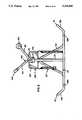
- FIG. 1is a perspective view of a preferred embodiment of an exercise apparatus constructed according to the principles of the present invention
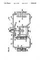
- FIG. 2is a front view of the preferred embodiment exercise apparatus shown in FIG. 1;
- FIG. 3is a rear view of the preferred embodiment exercise apparatus shown in FIG. 1;
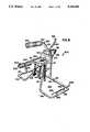
- FIG. 4is a left side view of the preferred embodiment exercise apparatus shown in FIG. 1;
- FIG. 5is a right side view of the preferred embodiment exercise apparatus shown in FIG. 1;
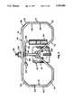
- FIG. 6is a top view of the preferred embodiment exercise apparatus shown in FIG. 1;
- FIG. 7is a bottom view of the preferred embodiment exercise apparatus shown in FIG. 1;
- FIG. 8is a perspective view of a alternative embodiment of an exercise apparatus constructed according to the principles of the present invention.
- FIG. 9is a front view of the alternative embodiment exercise apparatus shown in FIG. 8.
- FIG. 10is a rear view of the alternative embodiment exercise apparatus shown in FIG. 8;
- FIG. 11is a left side view of the alternative embodiment exercise apparatus shown in FIG. 8;
- FIG. 12is a right side view of the alternative embodiment exercise apparatus shown in FIG. 8;
- FIG. 13is a top view of the alternative embodiment exercise apparatus shown in FIG. 8;
- FIG. 14is a bottom view of the alternative embodiment exercise apparatus shown in FIG. 8;
- FIG. 15is a front view of the alternative embodiment exercise apparatus shown in FIGS. 8-14, in a first configuration with a person using the apparatus to perform abdominal flexions;
- FIG. 16ais a front view of the alternative embodiment exercise apparatus shown in FIGS. 8-14, in a second configuration with a person using the apparatus to perform lower back flexions;
- FIG. 16bis a front view of the alternative embodiment exercise apparatus shown in FIG. 16a, with the person using a support handle to return to an upright, seated position;
- FIG. 17is a front view of the alternative embodiment exercise apparatus shown in FIGS. 8-14, in a third configuration with a person using the apparatus to perform right side flexions;
- FIG. 18is a front view of the alternative embodiment exercise apparatus shown in FIGS. 8-14, in a fourth configuration with a person using the apparatus to perform left side flexions;
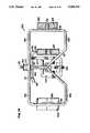
- FIG. 19is an enlarged left side view of the rotational resistance means comprising a part of the exercise apparatus shown in FIGS. 1-18;
- FIG. 20is an enlarged left side view of the adjustment knob and shaft member comprising a part of the rotational resistance means shown in FIG. 19;
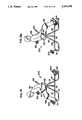
- FIG. 21is an enlarged and exploded perspective view of the rotational resistance means shown in FIG. 19.
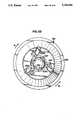
- FIG. 22is an enlarged front view of the rotatable friction member comprising a part of the rotational resistance means shown in FIG. 19.
- the exercise apparatus 100includes a support frame 101, a chair member 102, a foot anchor means 103, a foot brace means 104, a rotational resistance means 105, a rotational arm means 106, a pelvis stabilization means 107, and a thigh stabilization means 108.
- the support frame 101is constructed of one and one-half inch diameter steel tubing.
- the support frame 101includes a substantially planar base member 110, which is designed to rest upon a floor surface 109 when the apparatus 100 is in an operable position.
- the base member 110extends between first and second ends defined by the lateral portions of U-shaped first and second end members 111 and 112, respectively.
- Bolts 119a and 119bpass through mating holes in the end members 111 and 112 and their counterparts on opposing portions of the remainder of the base member 110 to secure the end members 111 and 112 relative to the remainder of the base member 110.
- a chair support member 113extends up from the front of the base member 110 intermediate the end members 111 and 112.
- the chair support member 113defines an oblique angle relative to the plane of the base member 110 and thus, the floor surface 109, and the chair support member 113 may be described as leaning toward the rear of the apparatus 100.
- a post member 114extends perpendicularly up from the rear of the base member 100 intermediate the end members 111 and 112, and a lateral member 115 extends between the chair support member 113 and the post member 114 to stabilize the support frame 101 and distribute the weight of a person sitting on the chair member 102.
- the chair member 102is rotatably mounted to the support frame 101 proximate the juncture between the chair support member 113 and the lateral member 115.
- a preferred embodiment of the chair member 102is disclosed-. in detail in U.S. Pat. No. 5,122,105, which was filed on Aug. 31, 1990, and is assigned to the same assignee as is the present application. To the extent that such disclosure is helpful in understanding the present invention, it is incorporated herein by reference.
- the chair member 102includes a seat member 121 and a back member 122.
- the back member 122includes a pair of wing members defining an elongate vertical slot 123 therebetween.
- the elongate vertical slot 123provides clearance for the spine of a person seated in the chair member 102, and hence, the back member 122 may be referred to as a split back member.
- the split back member 122provides clearance for a person's spine and comfortably engages the fleshy portions of the person's lower back and hips.
- a springy steel insertextends between the seat member 121 and the back member 122 to provide support for the person's back and yet allow the back member 122 to deflect relative to the seat member 121 as a person leans backward in the chair member 102.
- the one significant difference between the chair member 102 and that disclosed in U.S. Pat. No. 5,122,105is that the chair member 102 is rotatably mounted to the support frame 101.
- the seat member 121defines a sitting surface that is substantially horizontal relative to the floor surface 109 and is located at a first elevation above the floor surface 109.
- the chair member 102rotates about an axis perpendicular to the floor surface 109, so that the sitting surface remains parallel to the floor surface 109 independent of the orientation of the chair member 102.
- the axis of rotation of the chair member 102is positioned relative to the post member 114 such that the chair member 102 is free to completely rotate 360 degrees without interference from the post member 114 or any other structure.
- the foot anchor means 103is defined by the first end member 111 and includes first and second elbow portions 131 and 132, integrally joined by an intermediate transverse member 133.
- the elbow portions 131 and 132maintain the transverse member 133 at a second elevation above the floor surface 109 and relative to the base member 110.
- a person seated in the chair member 102may anchor his feet behind the transverse member 133 during the performance of abdominal flexions, as will be discussed in greater detail below.
- the foot brace means 104is defined by the second end member 112 and includes first an second elbow portions 141 and 142, integrally joined by an intermediate transverse member 143.
- the elbow portions 141 and 142maintain the transverse member 143 at a third elevation above the floor surface 109 and relative to the base member 110.
- a person seated in the chair member 102may brace his feet against the transverse member 143 during the performance of lower back flexions, as will be discussed in greater detail below.
- the foot anchor means 103 and the foot brace means 104are mirror images of one another, and the second elevation is equal to the third elevation.
- the post member 114supports the rotational resistance means 105, which is mounted on the rear side of the post member 114 at a fourth elevation above the floor surface 109.
- the rotational resistance means 105is mounted to the post member 114 above the point at which the lateral member 115 is connected to the post member 114.
- the rotational resistance means 105is designed to oppose rotation in a given direction up to a given load, beyond which point the rotational resistance means 105 rotates at a smooth and constant resistance.
- the rotational resistance means 105includes a fixed friction member 156 secured relative to the support frame 101 by means of a U-shaped bracket 157 and a tube member 158, both of which are rigidly secured to the post member 114.
- a housing member 170(shown in phantom in FIG. 19) conceals the tube member 158 and the interior of the U-shaped bracket 157.
- the fixed friction member 156has a conical internal surface 256 that is coated with a plastic known in the art as UH-MW.
- the conical internal surface 256faces rearward from the post member 114 and is designed to mate with a forwardly facing conical external surface 255 on a coaxially aligned rotatable friction member 155.
- the conical external surface 255is coated with rubber, and rotation of the rotatable friction member 155 relative to the fixed friction member 156 is resisted by a frictional force between the rubber-coated conical external surface 255 and the plastic-coated conical internal surface 256.
- a shaft member 154is coaxially aligned relative to the fixed friction member 156 and the rotatable friction member 155 and passes through centrally located openings therein.
- the shaft member 154has a first end that is rigidly secured to the rotational arm means 106, and an opposite, second end that secures to a frictional force adjustment knob 151.
- a large metal washer 159bis rigidly secured to the rotational arm means 106, and a large nylon washer 159a is positioned between the large metal washer 159b and the tube member 158.
- the washers 159a and 159bare included in the preferred embodiment to facilitate rotation of the rotational arm means 106 relative to the tube member 158.
- the shaft member 154passes through the large washers 159b and 159a, the tube member 158, the fixed friction member 156, the rotatable friction member 155, and a large washer 153, which is intermediate the rotatable friction member 155 and the knob 151. That portion of the shaft member 154 which passes through the rotatable friction member 155 has teeth 257 disposed about its circumference. In the embodiment shown in FIG. 22, the teeth 257 are part of a separate ring member 254 that secures to the shaft member 154 by means of a keyway arrangement.
- ratcheting member 258aUpon rotation of the shaft member 154 in a first shaft direction S1, one of the teeth 257 is engaged by one of a plurality of ratcheting members 258a-c, which are pivotally mounted on said rotatable friction member 155.
- the three ratcheting members 258are positioned about the perimeter of the thirty-two teeth 257 in such a manner that only one ratcheting member 258a-c is capable of engaging any of the teeth 257 at any given time.
- ratcheting member 258ais presently engaging one of the teeth 257, so that upon rotation of the shaft member 154 in the first shaft direction S1, the rotatable friction member rotates in conjunction with the shaft member 154 and relative to the fixed friction member 156.
- the frictional force adjustment knob 151is secured relative to the second end of the shaft member 154 by means of interengaging threads on the knob 151 and the second end of the shaft member 154.
- the shaft member 154passes through the large washer 153, which is located between the knob 151 and the rotatable friction member 155.
- a small washer 152a, a small thrust bearing 152b, and a small washer 152care located between the knob 151 and the large washer 153.
- the structureis such that rotation of the knob 151 in a first knob direction relative to the shaft member 154 forces the rotatable friction member 155 toward the fixed friction member 156, thereby increasing the frictional force between the conical internal surface 256 and the conical external surface 255. Conversely, rotation of the knob 151 in a second knob direction relative to the shaft member 154 relaxes the force of the rotatable friction member 155 against the fixed friction member 156, thereby decreasing the frictional force between the conical internal surface 256 and the conical external surface 255.
- the rotational resistance means 105provides rotational resistance in a single direction S1, counter-clockwise as you face the apparatus 100 (FIG. 2).
- the rotational resistance means 105upon release of a rotational load on the rotational resistance means 105, it does not automatically return to a start position.
- the resistance to rotationis entirely passive, and there is never a load acting upon the person exercising.
- an automatic return to a start positioncan be provided by adding some type of spring mechanism (not shown) to "unwind" the rotation.
- the spring forceshould be limited to what is necessary to return the rotational resistance means 105 to a start position, so that the resistance to rotation remains as passive as possible.
- the rotational arm means 106is operatively connected to the rotational resistance means 105 in such a manner that the rotational arm means 106 rotates in conjunction with the shaft member 154, the cone member 155 (in one direction S1), and the knob 151, relative to the fixed members the rotational resistance means 105, including the shaft support member 158 and the fixed friction member 156.
- the plane of rotation of the rotational arm means 106is perpendicular to the floor surface 109, as well as the lateral members 133 and 143.
- the rotational arm means 106includes a radial member 161 that is rigidly secured perpendicularly to the shaft member 154 and extends in a direction parallel to the plane of rotation.
- An orbital member 162extends perpendicularly from the radial member 161, and perpendicular to the plane of rotation. Recognizing that the plane of rotation of the rotational arm means 106 is proximate the rear of the apparatus 100, the orbital member 162 extends toward the front of the apparatus 100.
- the orbital member 162is covered by a pad member 163 that provides a more comfortable support, against which the person applies force against the resistance provided by the rotational resistance means 105.
- the rotational arm means 106further includes a support member 164 that extends perpendicularly from the radial member 161, and in a direction parallel to the plane of rotation.
- the support member 164has a handle member 165 at its distal end, the significance of which will be discussed below.
- the pelvis stabilization means 107includes a belt member, or mating strap members, the ends of which are mounted beneath the planform of the chair member 102. Designed to operate similar to a seat belt, the strap members secure about the waist of a person seated on the chair member 102 and stabilize the person's pelvis relative to the seat member 121 and the back member 122.
- the thigh stabilization means 108includes a tandem strap member, the end of which is mounted beneath the planform of the chair member 102. Extending out beyond the front of the chair member 102, the tandem strap member 108 secures separately about each of the legs of a person seated on the chair member 102, just below the person's knees, and stabilizes the person's thighs relative to the chair member 102.
- strap membersmay be fastened by velcro or buckles or other available means.
- the pelvis stabilization means 107 and the thigh stabilization means 108help to prevent a person from shifting the exercise load from the intended muscles to other, stronger muscles, which would thereby defeat the purpose of the specifically tailored exercise.
- an alternative embodiment of the present inventionis designated generally at 200.
- the alternative embodimentcorresponds to the preferred embodiment to the extent that like numerals are used to designate like parts on the respective embodiments.
- an alternative foot anchor means 203includes an extension member 231 that extends from an alternative first end member 211.
- the foot anchor means 203extends up from the floor surface 109 and away from the chair member 102, defining an oblique angle relative to the floor surface 109.
- the extension member 231is connected to a transverse member 232 to form a T-shape at an alternative second elevation above the floor surface 109.
- a person seated in the chair member 102is able to position one foot on each side of the extension member 231 and to the remote side of the transverse member 232.
- the transverse member 232is covered by a pad member 233 that provides a more comfortable support behind which the person's feet are intended to be anchored, as will be discussed in greater detail below.
- An alternative foot brace means 204includes a bracket member 242 that extends from an alternative second end member 212.
- the bracket memberextends up from the floor surface 109 and toward the chair member 102, defining an oblique angle relative to the floor surface 109.
- a platform member 243is mounted at a right angle to the bracket member 242 to face substantially toward the chair member 102.
- the platform member 243provides a surface at an alternative third elevation above the floor surface 109, against which the person's feet are intended to be braced, as will be discussed in greater detail below.
- the alternative embodiment 200is identical to the preferred embodiment 100.
- the apparatuswhen the chair member 102 is rotated to a first orientation facing toward the foot anchor means 203 (or 103 in the preferred embodiment), the apparatus is in a first configuration suitable for abdominal flexions.
- the person 199sits on the chair member 102 and secures the pelvis stabilization means 107 about his waist and the thigh stabilization means 108 about his legs.
- the person 199then extends his legs, making any necessary adjustment to the thigh stabilization means 108 in the process, so that his feet are positioned on opposite sides of the extension member 231 and to the remote side of the pad member 233, with the tops of his feet up against the underside of the pad member 233.
- the tops of the person's feetwould be positioned up against the underside of the lateral member 133.
- the person 199will notice the orbital member 162 extending in front of his chest.
- the person 199leans forward against the orbital member 162, and with his feet anchored behind the foot anchor means 203, the person 199 flexes his abdominal muscles to curl his torso forward and rotate the rotational arm means 106 against the resistance of the rotational resistance means 105.
- the person 199simply returns to an upright seated position upon completion of the forward curl, and the rotational arm means 106 follows.
- the person 199either retains the orbital member 162 as he returns to an upright seated position, or after returning to his starting position, the person 199 pulls on the handle member 165 to return the rotational arm means 106 to its starting position.
- the resistance provided by the rotational resistance means 105is one-way, and no significant resistance is offered to the return of the rotational arm means 106 to a start position (because the ratcheting members 258a-6 simply pass over the gear teeth 257).
- the relative positioning of the chair member 102 at the first elevation and the rotational resistance means 105 at the fourth elevationis such that the axis of rotation of the rotational resistance means 105 and rotational arm means 106 approximately aligns with the natural axis of rotation at the hips of the person 199 performing the abdominal flexions.
- the alignment of the rotational axes of the rotational arm means 106 and the person's waistassures corresponding paths of motion and thus, a constant resistance to motion throughout the range of the exercise.
- the relative positioning of the chair member 102 at the first elevation and the foot anchor means 203 at the alternative second elevation, as well as the overall distance therebetweenis calculated to accommodate persons of average size and within a range of such average size.
- first end member 211slidably engage their counterparts on the remainder of the base member 110, and series of mating holes are provided for bolts 119a, so that the distance between the foot anchor means 203 and the chair member 102 can be adjusted to accommodate persons of various sizes.
- the apparatuswhen the chair member 102 is rotated to a second orientation facing toward the foot brace means 204 (or 104 in the preferred embodiment), the apparatus is in a second configuration suitable for lower back flexions.
- the person 199sits on the chair member 102 and secures the pelvis stabilization means 107 about his waist and the thigh stabilization means 108 about his legs.
- the person 199then extends his legs, making any necessary adjustment to the thigh stabilization means 108 in the process, so that the bottoms of his feet are positioned squarely against the platform member 243. In the preferred embodiment, the bottoms of the person's feet would be positioned squarely against the lateral member 143.
- the person 199will notice the orbital member 162 extending behind his back.
- the person 199leans backward against the orbital member 162, and with his feet braced against the foot brace means 204, the person 199 flexes his lower back muscles to arch backward and rotate the rotational arm means 106 against the resistance of the rotational resistance means 105.
- the direction of rotationis the same as that for abdominal flexions because the chair has been rotated 180 degrees relative to the rotational resistance means 105 and the rotational arm means 106.
- the person 199simply returns to an upright seated position upon completion of the backward arch, and the rotational arm means 106 follows.
- the person 199either retains the orbital member 162 with one or both of his arms as he returns to an upright seated position, or after returning to his starting position, the person 199 pushes on the handle member 165 to return the rotational arm means 106 to its starting position.
- the support member 164may serve a second important function in connection with back flexion exercises, because it may become necessary for the person 199 to grip the handle member 165 and pull himself up relative to the support member 164 in order to return to an upright seated position.
- the ends of the second end member 212slidably engage their counterparts on the remainder of the base member 110, and series of mating holes are provided for bolts 119b, so that the distance between the foot brace means 204 and the chair member 102 can also be adjusted to accommodate persons of various sizes.
- the apparatus 100when the chair member 102 is rotated to a third orientation facing forward, away from the rotational resistance means 105, the apparatus 100 is in a third configuration suitable for right side flexions. When seated in this orientation, the person 199 will notice the orbital member 162 extending proximate his right side.
- the apparatus 100when the chair member 102 is rotated to a fourth orientation facing rearward, toward the rotational resistance means 105, the apparatus 100 is in a fourth configuration suitable for left side flexions. When seated in this orientation, the person 199 will notice the orbital member 162 extending proximate his left side.
Landscapes
- Health & Medical Sciences (AREA)
- Orthopedic Medicine & Surgery (AREA)
- General Health & Medical Sciences (AREA)
- Physical Education & Sports Medicine (AREA)
- Engineering & Computer Science (AREA)
- Biomedical Technology (AREA)
- Neurology (AREA)
- Pulmonology (AREA)
- Life Sciences & Earth Sciences (AREA)
- Biophysics (AREA)
- Rehabilitation Tools (AREA)
Abstract
Description
Claims (15)
Priority Applications (1)
| Application Number | Priority Date | Filing Date | Title |
|---|---|---|---|
| US07/751,732US5244446A (en) | 1991-08-29 | 1991-08-29 | Multi-purpose torso exercise apparatus |
Applications Claiming Priority (1)
| Application Number | Priority Date | Filing Date | Title |
|---|---|---|---|
| US07/751,732US5244446A (en) | 1991-08-29 | 1991-08-29 | Multi-purpose torso exercise apparatus |
Publications (1)
| Publication Number | Publication Date |
|---|---|
| US5244446Atrue US5244446A (en) | 1993-09-14 |
Family
ID=25023245
Family Applications (1)
| Application Number | Title | Priority Date | Filing Date |
|---|---|---|---|
| US07/751,732Expired - Fee RelatedUS5244446A (en) | 1991-08-29 | 1991-08-29 | Multi-purpose torso exercise apparatus |
Country Status (1)
| Country | Link |
|---|---|
| US (1) | US5244446A (en) |
Cited By (57)
| Publication number | Priority date | Publication date | Assignee | Title |
|---|---|---|---|---|
| USD357954S (en) | 1994-01-10 | 1995-05-02 | San-Ping Lee | Exerciser |
| US5472392A (en)* | 1993-09-08 | 1995-12-05 | Haan; Kenneth | Centrifugal resistance device for stationary bicycle trainer |
| USD379483S (en)* | 1995-03-01 | 1997-05-27 | Roadmaster Corporation | Combination abdominal and back exerciser |
| US5632710A (en)* | 1993-10-20 | 1997-05-27 | Roadmaster Corporation | Exercise apparatus |
| US6004246A (en)* | 1998-03-27 | 1999-12-21 | Medx 96, Inc. | Lower back exercise machine including leg engaging assembly for isolating the lower torso |
| US6773378B2 (en) | 2000-12-14 | 2004-08-10 | Steven O. Ross | Exercise device with true pivot point |
| US7070545B2 (en) | 2002-07-01 | 2006-07-04 | Nautilus, Inc. | Leg press and abdominal crunch exercise machine |
| US7083554B1 (en) | 1997-02-27 | 2006-08-01 | Nautilus, Inc. | Exercise machine with infinite position range limiter and automatic belt tensioning system |
| US7108641B2 (en) | 2000-05-03 | 2006-09-19 | Nautilus, Inc. | Exercise equipment with multi-positioning handles |
| US7115080B2 (en) | 2002-08-01 | 2006-10-03 | Nautilus, Inc. | Collapsible seat for combination hack squat and leg press machine |
| US20070037666A1 (en)* | 2003-05-21 | 2007-02-15 | Guy Gagnon | Orthopedic exerciser |
| US7223215B2 (en) | 2000-12-14 | 2007-05-29 | Bastyr Charles A | Exercise device with true pivot point |
| US7223213B2 (en) | 2002-08-08 | 2007-05-29 | Nautilus, Inc. | Dual-direction pulley system |
| US20080261784A1 (en)* | 2007-04-19 | 2008-10-23 | Gordon Albin Osbak | Oblique abdominal trainer |
| US20100056348A1 (en)* | 2008-08-26 | 2010-03-04 | Jamos Llc | Portable Mountable Upper-Body Exercise Device |
| US7922635B2 (en) | 2000-03-10 | 2011-04-12 | Nautilus, Inc. | Adjustable-load unitary multi-position bench exercise unit |
| US20120202654A1 (en)* | 2006-12-19 | 2012-08-09 | Bret Contreras | Exercise Apparatus and Methods of Use |
| US20130184130A1 (en)* | 2010-01-04 | 2013-07-18 | Mark Zachary Kyriacos | Exercise device for torso rotation and method of operating the same |
| US10226665B2 (en) | 2017-05-12 | 2019-03-12 | Kormel, LLC | Exercise apparatus for performing a gluteal bridge movement |
| US10388183B2 (en) | 2015-02-27 | 2019-08-20 | Icon Health & Fitness, Inc. | Encouraging achievement of health goals |
| US10709925B2 (en) | 2013-03-14 | 2020-07-14 | Icon Health & Fitness, Inc. | Strength training apparatus |
| US10758767B2 (en) | 2013-12-26 | 2020-09-01 | Icon Health & Fitness, Inc. | Resistance mechanism in a cable exercise machine |
| US10786706B2 (en) | 2018-07-13 | 2020-09-29 | Icon Health & Fitness, Inc. | Cycling shoe power sensors |
| US10918905B2 (en) | 2016-10-12 | 2021-02-16 | Icon Health & Fitness, Inc. | Systems and methods for reducing runaway resistance on an exercise device |
| US10940360B2 (en) | 2015-08-26 | 2021-03-09 | Icon Health & Fitness, Inc. | Strength exercise mechanisms |
| US10994173B2 (en) | 2016-05-13 | 2021-05-04 | Icon Health & Fitness, Inc. | Weight platform treadmill |
| US11000730B2 (en) | 2018-03-16 | 2021-05-11 | Icon Health & Fitness, Inc. | Elliptical exercise machine |
| US11013960B2 (en) | 2016-03-18 | 2021-05-25 | Icon Health & Fitness, Inc. | Exercise system including a stationary bicycle and a free weight cradle |
| US11033777B1 (en) | 2019-02-12 | 2021-06-15 | Icon Health & Fitness, Inc. | Stationary exercise machine |
| US11058913B2 (en) | 2017-12-22 | 2021-07-13 | Icon Health & Fitness, Inc. | Inclinable exercise machine |
| US11058914B2 (en) | 2016-07-01 | 2021-07-13 | Icon Health & Fitness, Inc. | Cooling methods for exercise equipment |
| US11187285B2 (en) | 2017-12-09 | 2021-11-30 | Icon Health & Fitness, Inc. | Systems and methods for selectively rotationally fixing a pedaled drivetrain |
| US11244751B2 (en) | 2012-10-19 | 2022-02-08 | Finish Time Holdings, Llc | Method and device for providing a person with training data of an athlete as the athlete is performing a swimming workout |
| US11298577B2 (en) | 2019-02-11 | 2022-04-12 | Ifit Inc. | Cable and power rack exercise machine |
| US11326673B2 (en) | 2018-06-11 | 2022-05-10 | Ifit Inc. | Increased durability linear actuator |
| WO2022101888A1 (en)* | 2020-11-16 | 2022-05-19 | Thomas Perrier | General bodybuilding apparatus |
| US11451108B2 (en) | 2017-08-16 | 2022-09-20 | Ifit Inc. | Systems and methods for axial impact resistance in electric motors |
| US11534651B2 (en) | 2019-08-15 | 2022-12-27 | Ifit Inc. | Adjustable dumbbell system |
| US11534654B2 (en) | 2019-01-25 | 2022-12-27 | Ifit Inc. | Systems and methods for an interactive pedaled exercise device |
| US11565148B2 (en) | 2016-03-18 | 2023-01-31 | Ifit Inc. | Treadmill with a scale mechanism in a motor cover |
| US11673036B2 (en) | 2019-11-12 | 2023-06-13 | Ifit Inc. | Exercise storage system |
| US11700905B2 (en) | 2014-03-10 | 2023-07-18 | Ifit Inc. | Pressure sensor to quantify work |
| US11794070B2 (en) | 2019-05-23 | 2023-10-24 | Ifit Inc. | Systems and methods for cooling an exercise device |
| US11850497B2 (en) | 2019-10-11 | 2023-12-26 | Ifit Inc. | Modular exercise device |
| US11878199B2 (en) | 2021-02-16 | 2024-01-23 | Ifit Inc. | Safety mechanism for an adjustable dumbbell |
| US11931621B2 (en) | 2020-03-18 | 2024-03-19 | Ifit Inc. | Systems and methods for treadmill drift avoidance |
| US11951377B2 (en) | 2020-03-24 | 2024-04-09 | Ifit Inc. | Leaderboard with irregularity flags in an exercise machine system |
| US12029961B2 (en) | 2020-03-24 | 2024-07-09 | Ifit Inc. | Flagging irregularities in user performance in an exercise machine system |
| US12029935B2 (en) | 2021-08-19 | 2024-07-09 | Ifit Inc. | Adjustment mechanism for an adjustable kettlebell |
| US12176009B2 (en) | 2021-12-30 | 2024-12-24 | Ifit Inc. | Systems and methods for synchronizing workout equipment with video files |
| US12219201B2 (en) | 2021-08-05 | 2025-02-04 | Ifit Inc. | Synchronizing video workout programs across multiple devices |
| US12263371B2 (en) | 2021-04-27 | 2025-04-01 | Ifit Inc. | Devices, systems, and methods for rotating a tread belt in two directions |
| US12280294B2 (en) | 2021-10-15 | 2025-04-22 | Ifit Inc. | Magnetic clutch for a pedaled drivetrain |
| US12350573B2 (en) | 2021-04-27 | 2025-07-08 | Ifit Inc. | Systems and methods for cross-training on exercise devices |
| US12350547B2 (en) | 2022-02-28 | 2025-07-08 | Ifit Inc. | Devices, systems, and methods for moving a movable step through a transition zone |
| US12409375B2 (en) | 2022-03-18 | 2025-09-09 | Ifit Inc. | Systems and methods for haptic simulation in incline exercise devices |
| US12433815B2 (en) | 2020-10-02 | 2025-10-07 | Ifit Inc. | Massage roller with pressure sensors |
Citations (26)
| Publication number | Priority date | Publication date | Assignee | Title |
|---|---|---|---|---|
| US3103357A (en)* | 1961-11-28 | 1963-09-10 | William E Berne | Resistance exercising apparatus |
| US3107953A (en)* | 1957-04-24 | 1963-10-22 | Goodrich Co B F | Bushing assembly |
| US3107952A (en)* | 1961-05-29 | 1963-10-22 | Goodrich Co B F | Bushing assembly |
| US3107951A (en)* | 1957-04-24 | 1963-10-22 | Goodrich Co B F | Bushing assembly |
| US3315959A (en)* | 1964-09-11 | 1967-04-25 | Carnielli Guido | Hinge and braking device for stationary rowing exercising apparatuses |
| US3861215A (en)* | 1970-10-28 | 1975-01-21 | Robert F Bradley | Exercising apparatus simulating weight lifting |
| US4372553A (en)* | 1980-11-03 | 1983-02-08 | Hatfield Frederick C | Weight lifting device and method of exercising |
| FR2544618A1 (en)* | 1983-04-25 | 1984-10-26 | Jaquet Hugues | Muscle-development apparatus with weights, with remote control of load selection and with holding pallet (small blade) for the limbs of the body |
| US4500089A (en)* | 1983-01-20 | 1985-02-19 | Nautilus Sports/Medical Industries, Inc. | Weight lifting lower back exercising machine |
| US4546971A (en)* | 1984-09-05 | 1985-10-15 | Paul Raasoch | Exercise device |
| US4566693A (en)* | 1982-06-07 | 1986-01-28 | Stretch Forming Corporation | Gravity traction apparatus |
| US4621807A (en)* | 1984-05-25 | 1986-11-11 | Universal Gym Equipment, Inc. | Leg and hip exercising apparatus |
| US4623144A (en)* | 1985-01-31 | 1986-11-18 | Diversified Products Corporation | Weight lifting type abdominal/back exercising apparatus |
| US4626112A (en)* | 1984-01-27 | 1986-12-02 | The B.F. Goodrich Company | Propeller bearing |
| US4627619A (en)* | 1985-01-31 | 1986-12-09 | Diversified Products Corporation | Abdominal and back weight type exercising device |
| US4678186A (en)* | 1986-01-17 | 1987-07-07 | Isotechnologies, Inc. | Pelvic restraint for exercise apparatus |
| US4725056A (en)* | 1985-11-27 | 1988-02-16 | Lumex, Inc. | Leg stabilization for a trunk extension/flexion test, rehabilitation and exercise machine |
| US4728102A (en)* | 1986-04-28 | 1988-03-01 | P.S.I. Nordic Track, Inc. | Resistance indicator for frictionally resistant exercise device |
| US4753438A (en)* | 1983-10-21 | 1988-06-28 | Rams Manufacturing, Inc. | Back and gluteus maximus exerciser and method of using same |
| US4834396A (en)* | 1986-07-09 | 1989-05-30 | Josef Schnell | Multi-exercising apparatus |
| US4836536A (en)* | 1987-06-11 | 1989-06-06 | Arthur Jones | Apparatus for exercising muscles of the lower trunk of the human body |
| US4884801A (en)* | 1987-11-09 | 1989-12-05 | Josef Schnell | Load applying driving apparatus for an exercise device |
| US4893812A (en)* | 1988-01-28 | 1990-01-16 | Dawson Jr Fredric O | Adjustable multipurpose trunk exerciser |
| US4979734A (en)* | 1988-10-06 | 1990-12-25 | Sims Anthony M | Multi-purpose hydraulic exercise apparatus |
| US5056779A (en)* | 1990-07-20 | 1991-10-15 | Nautilus Acquisition Corporation | Torso exercise machine with range limiter |
| US5110121A (en)* | 1990-09-28 | 1992-05-05 | Foster Daniel N | Exercise chair for the lower back |
- 1991
- 1991-08-29USUS07/751,732patent/US5244446A/ennot_activeExpired - Fee Related
Patent Citations (26)
| Publication number | Priority date | Publication date | Assignee | Title |
|---|---|---|---|---|
| US3107953A (en)* | 1957-04-24 | 1963-10-22 | Goodrich Co B F | Bushing assembly |
| US3107951A (en)* | 1957-04-24 | 1963-10-22 | Goodrich Co B F | Bushing assembly |
| US3107952A (en)* | 1961-05-29 | 1963-10-22 | Goodrich Co B F | Bushing assembly |
| US3103357A (en)* | 1961-11-28 | 1963-09-10 | William E Berne | Resistance exercising apparatus |
| US3315959A (en)* | 1964-09-11 | 1967-04-25 | Carnielli Guido | Hinge and braking device for stationary rowing exercising apparatuses |
| US3861215A (en)* | 1970-10-28 | 1975-01-21 | Robert F Bradley | Exercising apparatus simulating weight lifting |
| US4372553A (en)* | 1980-11-03 | 1983-02-08 | Hatfield Frederick C | Weight lifting device and method of exercising |
| US4566693A (en)* | 1982-06-07 | 1986-01-28 | Stretch Forming Corporation | Gravity traction apparatus |
| US4500089A (en)* | 1983-01-20 | 1985-02-19 | Nautilus Sports/Medical Industries, Inc. | Weight lifting lower back exercising machine |
| FR2544618A1 (en)* | 1983-04-25 | 1984-10-26 | Jaquet Hugues | Muscle-development apparatus with weights, with remote control of load selection and with holding pallet (small blade) for the limbs of the body |
| US4753438A (en)* | 1983-10-21 | 1988-06-28 | Rams Manufacturing, Inc. | Back and gluteus maximus exerciser and method of using same |
| US4626112A (en)* | 1984-01-27 | 1986-12-02 | The B.F. Goodrich Company | Propeller bearing |
| US4621807A (en)* | 1984-05-25 | 1986-11-11 | Universal Gym Equipment, Inc. | Leg and hip exercising apparatus |
| US4546971A (en)* | 1984-09-05 | 1985-10-15 | Paul Raasoch | Exercise device |
| US4623144A (en)* | 1985-01-31 | 1986-11-18 | Diversified Products Corporation | Weight lifting type abdominal/back exercising apparatus |
| US4627619A (en)* | 1985-01-31 | 1986-12-09 | Diversified Products Corporation | Abdominal and back weight type exercising device |
| US4725056A (en)* | 1985-11-27 | 1988-02-16 | Lumex, Inc. | Leg stabilization for a trunk extension/flexion test, rehabilitation and exercise machine |
| US4678186A (en)* | 1986-01-17 | 1987-07-07 | Isotechnologies, Inc. | Pelvic restraint for exercise apparatus |
| US4728102A (en)* | 1986-04-28 | 1988-03-01 | P.S.I. Nordic Track, Inc. | Resistance indicator for frictionally resistant exercise device |
| US4834396A (en)* | 1986-07-09 | 1989-05-30 | Josef Schnell | Multi-exercising apparatus |
| US4836536A (en)* | 1987-06-11 | 1989-06-06 | Arthur Jones | Apparatus for exercising muscles of the lower trunk of the human body |
| US4884801A (en)* | 1987-11-09 | 1989-12-05 | Josef Schnell | Load applying driving apparatus for an exercise device |
| US4893812A (en)* | 1988-01-28 | 1990-01-16 | Dawson Jr Fredric O | Adjustable multipurpose trunk exerciser |
| US4979734A (en)* | 1988-10-06 | 1990-12-25 | Sims Anthony M | Multi-purpose hydraulic exercise apparatus |
| US5056779A (en)* | 1990-07-20 | 1991-10-15 | Nautilus Acquisition Corporation | Torso exercise machine with range limiter |
| US5110121A (en)* | 1990-09-28 | 1992-05-05 | Foster Daniel N | Exercise chair for the lower back |
Non-Patent Citations (2)
| Title |
|---|
| "Document A" Torsilastic Product Literature. |
| Document A Torsilastic Product Literature.* |
Cited By (92)
| Publication number | Priority date | Publication date | Assignee | Title |
|---|---|---|---|---|
| US5472392A (en)* | 1993-09-08 | 1995-12-05 | Haan; Kenneth | Centrifugal resistance device for stationary bicycle trainer |
| US5632710A (en)* | 1993-10-20 | 1997-05-27 | Roadmaster Corporation | Exercise apparatus |
| USD357954S (en) | 1994-01-10 | 1995-05-02 | San-Ping Lee | Exerciser |
| USD379483S (en)* | 1995-03-01 | 1997-05-27 | Roadmaster Corporation | Combination abdominal and back exerciser |
| US7083554B1 (en) | 1997-02-27 | 2006-08-01 | Nautilus, Inc. | Exercise machine with infinite position range limiter and automatic belt tensioning system |
| US6004246A (en)* | 1998-03-27 | 1999-12-21 | Medx 96, Inc. | Lower back exercise machine including leg engaging assembly for isolating the lower torso |
| US7922635B2 (en) | 2000-03-10 | 2011-04-12 | Nautilus, Inc. | Adjustable-load unitary multi-position bench exercise unit |
| US7108641B2 (en) | 2000-05-03 | 2006-09-19 | Nautilus, Inc. | Exercise equipment with multi-positioning handles |
| US7608028B2 (en) | 2000-05-03 | 2009-10-27 | Nautilus, Inc. | Exercise equipment with multi-positioning handles |
| US7223215B2 (en) | 2000-12-14 | 2007-05-29 | Bastyr Charles A | Exercise device with true pivot point |
| US6773378B2 (en) | 2000-12-14 | 2004-08-10 | Steven O. Ross | Exercise device with true pivot point |
| US7070545B2 (en) | 2002-07-01 | 2006-07-04 | Nautilus, Inc. | Leg press and abdominal crunch exercise machine |
| US7608022B2 (en) | 2002-07-01 | 2009-10-27 | Nautilus, Inc. | Leg press and abdominal crunch exercise machine |
| US7115080B2 (en) | 2002-08-01 | 2006-10-03 | Nautilus, Inc. | Collapsible seat for combination hack squat and leg press machine |
| US7223213B2 (en) | 2002-08-08 | 2007-05-29 | Nautilus, Inc. | Dual-direction pulley system |
| US20070037666A1 (en)* | 2003-05-21 | 2007-02-15 | Guy Gagnon | Orthopedic exerciser |
| US8070659B2 (en)* | 2003-05-21 | 2011-12-06 | Robovic, NC. | Orthopedic exerciser |
| US20120202654A1 (en)* | 2006-12-19 | 2012-08-09 | Bret Contreras | Exercise Apparatus and Methods of Use |
| US20080261784A1 (en)* | 2007-04-19 | 2008-10-23 | Gordon Albin Osbak | Oblique abdominal trainer |
| US20100056348A1 (en)* | 2008-08-26 | 2010-03-04 | Jamos Llc | Portable Mountable Upper-Body Exercise Device |
| US8012070B2 (en)* | 2008-08-26 | 2011-09-06 | Jamos Llc | Portable mountable upper-body exercise device |
| US20130184130A1 (en)* | 2010-01-04 | 2013-07-18 | Mark Zachary Kyriacos | Exercise device for torso rotation and method of operating the same |
| US9302143B2 (en)* | 2010-01-04 | 2016-04-05 | Chesed Direct Holdings Ltd. | Exercise device for torso rotation and method of operating the same |
| US11810656B2 (en) | 2012-10-19 | 2023-11-07 | Finish Time Holdings, Llc | System for providing a coach with live training data of an athlete as the athlete is training |
| US11244751B2 (en) | 2012-10-19 | 2022-02-08 | Finish Time Holdings, Llc | Method and device for providing a person with training data of an athlete as the athlete is performing a swimming workout |
| US12340891B2 (en) | 2012-10-19 | 2025-06-24 | Finish Time Network LLC | System and method for providing a trainer with live training data of an individual as the individual is performing a training workout |
| US11923066B2 (en) | 2012-10-19 | 2024-03-05 | Finish Time Holdings, Llc | System and method for providing a trainer with live training data of an individual as the individual is performing a training workout |
| US11322240B2 (en) | 2012-10-19 | 2022-05-03 | Finish Time Holdings, Llc | Method and device for providing a person with training data of an athlete as the athlete is performing a running workout |
| US10709925B2 (en) | 2013-03-14 | 2020-07-14 | Icon Health & Fitness, Inc. | Strength training apparatus |
| US11878206B2 (en) | 2013-03-14 | 2024-01-23 | Ifit Inc. | Strength training apparatus |
| US10953268B1 (en) | 2013-03-14 | 2021-03-23 | Icon Health & Fitness, Inc. | Strength training apparatus |
| US11338169B2 (en) | 2013-03-14 | 2022-05-24 | IFIT, Inc. | Strength training apparatus |
| US10967214B1 (en) | 2013-12-26 | 2021-04-06 | Icon Health & Fitness, Inc. | Cable exercise machine |
| US10758767B2 (en) | 2013-12-26 | 2020-09-01 | Icon Health & Fitness, Inc. | Resistance mechanism in a cable exercise machine |
| US11700905B2 (en) | 2014-03-10 | 2023-07-18 | Ifit Inc. | Pressure sensor to quantify work |
| US10388183B2 (en) | 2015-02-27 | 2019-08-20 | Icon Health & Fitness, Inc. | Encouraging achievement of health goals |
| US10940360B2 (en) | 2015-08-26 | 2021-03-09 | Icon Health & Fitness, Inc. | Strength exercise mechanisms |
| US12029944B2 (en) | 2016-03-18 | 2024-07-09 | Ifit Inc. | Stationary exercise machine configured to execute a programmed workout with aerobic portions and lifting portions |
| US12029943B2 (en) | 2016-03-18 | 2024-07-09 | Ifit Inc. | Stationary exercise machine configured to execute a programmed workout with aerobic portions and lifting portions |
| US12023549B2 (en) | 2016-03-18 | 2024-07-02 | Ifit Inc. | Stationary exercise machine configured to execute a programmed workout with aerobic portions and lifting portions |
| US11794075B2 (en) | 2016-03-18 | 2023-10-24 | Ifit Inc. | Stationary exercise machine configured to execute a programmed workout with aerobic portions and lifting portions |
| US11013960B2 (en) | 2016-03-18 | 2021-05-25 | Icon Health & Fitness, Inc. | Exercise system including a stationary bicycle and a free weight cradle |
| US11565148B2 (en) | 2016-03-18 | 2023-01-31 | Ifit Inc. | Treadmill with a scale mechanism in a motor cover |
| US10994173B2 (en) | 2016-05-13 | 2021-05-04 | Icon Health & Fitness, Inc. | Weight platform treadmill |
| US11779812B2 (en) | 2016-05-13 | 2023-10-10 | Ifit Inc. | Treadmill configured to automatically determine user exercise movement |
| US11058914B2 (en) | 2016-07-01 | 2021-07-13 | Icon Health & Fitness, Inc. | Cooling methods for exercise equipment |
| US10918905B2 (en) | 2016-10-12 | 2021-02-16 | Icon Health & Fitness, Inc. | Systems and methods for reducing runaway resistance on an exercise device |
| US10610729B2 (en) | 2017-05-12 | 2020-04-07 | Kormel LLC | Exercise apparatus for performing a gluteal bridge movement |
| US12350548B2 (en) | 2017-05-12 | 2025-07-08 | Kormel, LLC | Exercise apparatus for performing a gluteal bridge movement |
| US11130018B2 (en) | 2017-05-12 | 2021-09-28 | Kormel LLC | Exercise apparatus for performing a gluteal bridge movement |
| US10226665B2 (en) | 2017-05-12 | 2019-03-12 | Kormel, LLC | Exercise apparatus for performing a gluteal bridge movement |
| US11633645B2 (en) | 2017-05-12 | 2023-04-25 | Kormel LLC | Exercise apparatus for performing a gluteal bridge movement |
| US11451108B2 (en) | 2017-08-16 | 2022-09-20 | Ifit Inc. | Systems and methods for axial impact resistance in electric motors |
| US11187285B2 (en) | 2017-12-09 | 2021-11-30 | Icon Health & Fitness, Inc. | Systems and methods for selectively rotationally fixing a pedaled drivetrain |
| US12270441B2 (en) | 2017-12-09 | 2025-04-08 | Ifit Inc. | Systems and methods for selectively rotationally fixing a pedaled drivetrain |
| US11708874B2 (en) | 2017-12-09 | 2023-07-25 | Ifit Inc. | Systems and methods for selectively rotationally fixing a pedaled drivetrain |
| US11680611B2 (en) | 2017-12-09 | 2023-06-20 | Ifit Inc. | Systems and methods for selectively rotationally fixing a pedaled drivetrain |
| US11058913B2 (en) | 2017-12-22 | 2021-07-13 | Icon Health & Fitness, Inc. | Inclinable exercise machine |
| US11596830B2 (en) | 2018-03-16 | 2023-03-07 | Ifit Inc. | Elliptical exercise machine |
| US11000730B2 (en) | 2018-03-16 | 2021-05-11 | Icon Health & Fitness, Inc. | Elliptical exercise machine |
| US11326673B2 (en) | 2018-06-11 | 2022-05-10 | Ifit Inc. | Increased durability linear actuator |
| US12005315B2 (en) | 2018-07-13 | 2024-06-11 | Ifit Inc. | Cycling shoe power sensors |
| US10786706B2 (en) | 2018-07-13 | 2020-09-29 | Icon Health & Fitness, Inc. | Cycling shoe power sensors |
| US11534654B2 (en) | 2019-01-25 | 2022-12-27 | Ifit Inc. | Systems and methods for an interactive pedaled exercise device |
| US11452903B2 (en) | 2019-02-11 | 2022-09-27 | Ifit Inc. | Exercise machine |
| US11642564B2 (en) | 2019-02-11 | 2023-05-09 | Ifit Inc. | Exercise machine |
| US11298577B2 (en) | 2019-02-11 | 2022-04-12 | Ifit Inc. | Cable and power rack exercise machine |
| US11033777B1 (en) | 2019-02-12 | 2021-06-15 | Icon Health & Fitness, Inc. | Stationary exercise machine |
| US11951358B2 (en) | 2019-02-12 | 2024-04-09 | Ifit Inc. | Encoding exercise machine control commands in subtitle streams |
| US11058918B1 (en) | 2019-02-12 | 2021-07-13 | Icon Health & Fitness, Inc. | Producing a workout video to control a stationary exercise machine |
| US11426633B2 (en) | 2019-02-12 | 2022-08-30 | Ifit Inc. | Controlling an exercise machine using a video workout program |
| US11794070B2 (en) | 2019-05-23 | 2023-10-24 | Ifit Inc. | Systems and methods for cooling an exercise device |
| US11534651B2 (en) | 2019-08-15 | 2022-12-27 | Ifit Inc. | Adjustable dumbbell system |
| US11850497B2 (en) | 2019-10-11 | 2023-12-26 | Ifit Inc. | Modular exercise device |
| US12296247B2 (en) | 2019-10-11 | 2025-05-13 | Ifit Inc. | Modular exercise device |
| US11673036B2 (en) | 2019-11-12 | 2023-06-13 | Ifit Inc. | Exercise storage system |
| US11931621B2 (en) | 2020-03-18 | 2024-03-19 | Ifit Inc. | Systems and methods for treadmill drift avoidance |
| US12029961B2 (en) | 2020-03-24 | 2024-07-09 | Ifit Inc. | Flagging irregularities in user performance in an exercise machine system |
| US11951377B2 (en) | 2020-03-24 | 2024-04-09 | Ifit Inc. | Leaderboard with irregularity flags in an exercise machine system |
| US12433815B2 (en) | 2020-10-02 | 2025-10-07 | Ifit Inc. | Massage roller with pressure sensors |
| FR3116206A1 (en)* | 2020-11-16 | 2022-05-20 | Thomas Perrier | General weight machine |
| WO2022101888A1 (en)* | 2020-11-16 | 2022-05-19 | Thomas Perrier | General bodybuilding apparatus |
| US12239872B2 (en) | 2021-02-16 | 2025-03-04 | Ifit Inc. | Safety mechanism for an adjustable dumbbell |
| US11878199B2 (en) | 2021-02-16 | 2024-01-23 | Ifit Inc. | Safety mechanism for an adjustable dumbbell |
| US12350573B2 (en) | 2021-04-27 | 2025-07-08 | Ifit Inc. | Systems and methods for cross-training on exercise devices |
| US12263371B2 (en) | 2021-04-27 | 2025-04-01 | Ifit Inc. | Devices, systems, and methods for rotating a tread belt in two directions |
| US12219201B2 (en) | 2021-08-05 | 2025-02-04 | Ifit Inc. | Synchronizing video workout programs across multiple devices |
| US12029935B2 (en) | 2021-08-19 | 2024-07-09 | Ifit Inc. | Adjustment mechanism for an adjustable kettlebell |
| US12280294B2 (en) | 2021-10-15 | 2025-04-22 | Ifit Inc. | Magnetic clutch for a pedaled drivetrain |
| US12176009B2 (en) | 2021-12-30 | 2024-12-24 | Ifit Inc. | Systems and methods for synchronizing workout equipment with video files |
| US12350547B2 (en) | 2022-02-28 | 2025-07-08 | Ifit Inc. | Devices, systems, and methods for moving a movable step through a transition zone |
| US12409375B2 (en) | 2022-03-18 | 2025-09-09 | Ifit Inc. | Systems and methods for haptic simulation in incline exercise devices |
Similar Documents
| Publication | Publication Date | Title |
|---|---|---|
| US5244446A (en) | Multi-purpose torso exercise apparatus | |
| US5580338A (en) | Portable, upper body, exercise machine | |
| US10391350B2 (en) | Isometric exercise apparatus and storage rack therefor | |
| US5217487A (en) | Back therapy system | |
| US6461284B1 (en) | Spherical back exerciser apparatus | |
| US6171219B1 (en) | Calf exercise apparatus | |
| US6213923B1 (en) | Back exercise device | |
| US5795276A (en) | Stretching and exercise device | |
| US5284131A (en) | Therapeutic exercise device for legs | |
| US5730688A (en) | Portable abdominal-lumbar exercise device | |
| US8113997B2 (en) | Ab wave abdominal exerciser | |
| US5330402A (en) | Exercising device | |
| US6676577B2 (en) | Apparatus for isolated, closed chain exercise of a person's quadriceps muscles | |
| US7476188B2 (en) | Torso exercise device | |
| US6113522A (en) | Exercise apparatus | |
| US6056676A (en) | Exercise device and method of using same | |
| US5704880A (en) | Device for an arm free inclined treadmill workout | |
| US20040229734A1 (en) | Exercise methods and apparatus | |
| US10888476B2 (en) | Standing chair | |
| CA2193355A1 (en) | Abdominal exercise device | |
| US6485398B1 (en) | Exercise apparatus | |
| US5743837A (en) | Body mounted muscle exercise device and method | |
| US6050644A (en) | Portable armrest | |
| US20070155602A1 (en) | Sit-up exercise bench | |
| US20200188730A1 (en) | Leg and hip exercise device and method |
Legal Events
| Date | Code | Title | Description |
|---|---|---|---|
| AS | Assignment | Owner name:NORDIC TRACK, INC., A CORP. OF MN, MINNESOTA Free format text:ASSIGNMENT OF ASSIGNORS INTEREST.;ASSIGNORS:ENGEL, TIMOTHY S.;CAMPBELL, FRANK W.;CUTTER, WESTON L.;REEL/FRAME:005821/0979 Effective date:19910821 | |
| AS | Assignment | Owner name:FIRST NATIONAL BANK OF BOSTON, THE, AS ADMINISTRAT Free format text:ASSIGNMENT OF ASSIGNORS INTEREST;ASSIGNOR:NORDICTRAK, INC.;REEL/FRAME:007919/0370 Effective date:19960417 | |
| REMI | Maintenance fee reminder mailed | ||
| FPAY | Fee payment | Year of fee payment:4 | |
| SULP | Surcharge for late payment | ||
| AS | Assignment | Owner name:BANKBOSTON, N.A. (F/K/A THE FIRST NATIONAL BANK OF Free format text:AMENDED AND RESTATED PATENT COLLATERAL ASSIGNMENT AND SECURITY AGREEMENT;ASSIGNORS:NORDIC TRACK, INC.;SMITH & HAWKEN, LTD.;REEL/FRAME:009516/0160 Effective date:19980728 | |
| AS | Assignment | Owner name:ICON HEALTH & FITNESS, INC., UTAH Free format text:ASSIGNMENT OF ASSIGNORS INTEREST;ASSIGNORS:NORDICTRACK, INC.;NORDIC ADVANTAGE, INC.;REEL/FRAME:009678/0570 Effective date:19981223 | |
| AS | Assignment | Owner name:NORDICTRACK, INC., MINNESOTA Free format text:RELEASE OF SECURITY INTERESTS;ASSIGNOR:BANKBOSTON, N.A. (FKA FIRST NATIONAL BANK OF BOSTON);REEL/FRAME:009925/0855 Effective date:19981223 Owner name:NORDIC ADVANTAGE, INC., MINNESOTA Free format text:RELEASE OF SECURITY INTERESTS;ASSIGNOR:BANKBOSTON, N.A. (FKA FIRST NATIONAL BANK OF BOSTON);REEL/FRAME:009925/0855 Effective date:19981223 | |
| AS | Assignment | Owner name:GENERAL ELECTRIC CAPITAL CORPORATION, ILLINOIS Free format text:SECURITY INTEREST;ASSIGNOR:ICON HEALTH & FITNESS, INC.;REEL/FRAME:009935/0758 Effective date:19981223 Owner name:GENERAL ELECTRIC CORPORATION, ILLINOIS Free format text:SECURITY INTEREST;ASSIGNOR:ICON HEALTH & FITNESS, INC.;REEL/FRAME:009935/0092 Effective date:19981223 | |
| FEPP | Fee payment procedure | Free format text:PAYER NUMBER DE-ASSIGNED (ORIGINAL EVENT CODE: RMPN); ENTITY STATUS OF PATENT OWNER: LARGE ENTITY Free format text:PAYOR NUMBER ASSIGNED (ORIGINAL EVENT CODE: ASPN); ENTITY STATUS OF PATENT OWNER: LARGE ENTITY | |
| FPAY | Fee payment | Year of fee payment:8 | |
| AS | Assignment | Owner name:GENERAL ELECTRIC CAPITAL CORPORATION, ILLINOIS Free format text:ASSIGNMENT OF ASSIGNORS INTEREST;ASSIGNOR:ICON IP, INC.;REEL/FRAME:012036/0191 Effective date:20010629 Owner name:GENERAL ELECTRIC CAPITAL CORPORATION, ILLINOIS Free format text:SECURITY AGREEMENT;ASSIGNOR:ICON IP, INC.;REEL/FRAME:012036/0191 Effective date:20010629 | |
| AS | Assignment | Owner name:ICON IP, INC., UTAH Free format text:ASSIGNMENT OF ASSIGNORS INTEREST;ASSIGNOR:ICON HEALTH & FITNESS, INC.;REEL/FRAME:012365/0100 Effective date:20010629 | |
| AS | Assignment | Owner name:GENERAL ELECTRIC CAPITAL CORPORATION, AS AGENT, CONNECTICUT Free format text:SECURITY INTEREST;ASSIGNOR:ICON IP, INC.;REEL/FRAME:012841/0049 Effective date:20020409 Owner name:GENERAL ELECTRIC CAPITAL CORPORATION, AS AGENT, CO Free format text:SECURITY INTEREST;ASSIGNOR:ICON IP, INC.;REEL/FRAME:012841/0049 Effective date:20020409 | |
| REMI | Maintenance fee reminder mailed | ||
| LAPS | Lapse for failure to pay maintenance fees | ||
| STCH | Information on status: patent discontinuation | Free format text:PATENT EXPIRED DUE TO NONPAYMENT OF MAINTENANCE FEES UNDER 37 CFR 1.362 | |
| AS | Assignment | Owner name:ICON IP, INC., UTAH Free format text:RELEASE OF SECURITY INTEREST IN PATENTS;ASSIGNOR:GENERAL ELECTRIC CAPITAL CORPORATION, AS AGENT;REEL/FRAME:016722/0811 Effective date:20051031 Owner name:ICON IP, INC., UTAH Free format text:RELEASE OF SECURITY INTEREST IN PATENTS;ASSIGNOR:GENERAL ELECTRIC CAPITAL CORPORATION, AS AGENT;REEL/FRAME:016722/0632 Effective date:20051031 | |
| FP | Lapsed due to failure to pay maintenance fee | Effective date:20050914 |